EP3698124B1 - Verfahren zur stimulated-emission-depletion-mikroskopie mit hoher räumlicher auflösung - Google Patents
Verfahren zur stimulated-emission-depletion-mikroskopie mit hoher räumlicher auflösung Download PDFInfo
- Publication number
- EP3698124B1 EP3698124B1 EP18815011.4A EP18815011A EP3698124B1 EP 3698124 B1 EP3698124 B1 EP 3698124B1 EP 18815011 A EP18815011 A EP 18815011A EP 3698124 B1 EP3698124 B1 EP 3698124B1
- Authority
- EP
- European Patent Office
- Prior art keywords
- sted
- image
- modulation
- fluorescence
- intensity
- Prior art date
- Legal status (The legal status is an assumption and is not a legal conclusion. Google has not performed a legal analysis and makes no representation as to the accuracy of the status listed.)
- Active
Links
Images




Classifications
-
- G—PHYSICS
- G01—MEASURING; TESTING
- G01N—INVESTIGATING OR ANALYSING MATERIALS BY DETERMINING THEIR CHEMICAL OR PHYSICAL PROPERTIES
- G01N21/00—Investigating or analysing materials by the use of optical means, i.e. using sub-millimetre waves, infrared, visible or ultraviolet light
- G01N21/62—Systems in which the material investigated is excited whereby it emits light or causes a change in wavelength of the incident light
- G01N21/63—Systems in which the material investigated is excited whereby it emits light or causes a change in wavelength of the incident light optically excited
- G01N21/64—Fluorescence; Phosphorescence
- G01N21/6408—Fluorescence; Phosphorescence with measurement of decay time, time resolved fluorescence
-
- G—PHYSICS
- G02—OPTICS
- G02B—OPTICAL ELEMENTS, SYSTEMS OR APPARATUS
- G02B21/00—Microscopes
- G02B21/0004—Microscopes specially adapted for specific applications
- G02B21/002—Scanning microscopes
- G02B21/0024—Confocal scanning microscopes (CSOMs) or confocal "macroscopes"; Accessories which are not restricted to use with CSOMs, e.g. sample holders
- G02B21/0052—Optical details of the image generation
- G02B21/0076—Optical details of the image generation arrangements using fluorescence or luminescence
-
- G—PHYSICS
- G01—MEASURING; TESTING
- G01N—INVESTIGATING OR ANALYSING MATERIALS BY DETERMINING THEIR CHEMICAL OR PHYSICAL PROPERTIES
- G01N21/00—Investigating or analysing materials by the use of optical means, i.e. using sub-millimetre waves, infrared, visible or ultraviolet light
- G01N21/62—Systems in which the material investigated is excited whereby it emits light or causes a change in wavelength of the incident light
- G01N21/63—Systems in which the material investigated is excited whereby it emits light or causes a change in wavelength of the incident light optically excited
- G01N21/64—Fluorescence; Phosphorescence
- G01N21/645—Specially adapted constructive features of fluorimeters
- G01N21/6456—Spatial resolved fluorescence measurements; Imaging
- G01N21/6458—Fluorescence microscopy
-
- G—PHYSICS
- G01—MEASURING; TESTING
- G01N—INVESTIGATING OR ANALYSING MATERIALS BY DETERMINING THEIR CHEMICAL OR PHYSICAL PROPERTIES
- G01N21/00—Investigating or analysing materials by the use of optical means, i.e. using sub-millimetre waves, infrared, visible or ultraviolet light
- G01N21/62—Systems in which the material investigated is excited whereby it emits light or causes a change in wavelength of the incident light
- G01N21/63—Systems in which the material investigated is excited whereby it emits light or causes a change in wavelength of the incident light optically excited
- G01N21/64—Fluorescence; Phosphorescence
- G01N21/6486—Measuring fluorescence of biological material, e.g. DNA, RNA, cells
-
- G—PHYSICS
- G02—OPTICS
- G02B—OPTICAL ELEMENTS, SYSTEMS OR APPARATUS
- G02B21/00—Microscopes
- G02B21/0004—Microscopes specially adapted for specific applications
- G02B21/002—Scanning microscopes
- G02B21/0024—Confocal scanning microscopes (CSOMs) or confocal "macroscopes"; Accessories which are not restricted to use with CSOMs, e.g. sample holders
- G02B21/008—Details of detection or image processing, including general computer control
- G02B21/0084—Details of detection or image processing, including general computer control time-scale detection, e.g. strobed, ultra-fast, heterodyne detection
-
- G—PHYSICS
- G02—OPTICS
- G02B—OPTICAL ELEMENTS, SYSTEMS OR APPARATUS
- G02B21/00—Microscopes
- G02B21/36—Microscopes arranged for photographic purposes or projection purposes or digital imaging or video purposes including associated control and data processing arrangements
- G02B21/365—Control or image processing arrangements for digital or video microscopes
Definitions
- the present invention relates to a method for increasing the optical resolution of a stimulated emission depletion microscope, or STED microscope ( Stimulated Emission Depletion ) based on the modulation of the intensity of a STED beam on an arbitrary time scale during the acquisition of an image and the analysis of the induced dynamics, without increasing the intensity of the STED beam and in a simple and economic manner.
- STED microscope Stimulated Emission Depletion
- Such method is based on the principle that the fluorescence at the centre of an observation volume is not modulated, while the fluorescence at the periphery of said volume is modulated.
- the exploitation of this difference in the modulation of the fluorescence signal entails an increase in the spatial resolution.
- STED microscopy is one of the many different types of super-resolution microscopy techniques which have been recently developed to increase spatial resolution through exceeding the limit of diffraction of conventional light microscopy.
- STED microscopy The main application of STED microscopy is directed to the study of sub-cellular architectures and dynamics and takes advantage of the non-linear response of fluorophores commonly used for marking biological samples.
- One sample is excited with a first radiation beam, the excitation beam, and the fluorescence is measured in a conventional manner.
- One donut-shaped second radiation beam, the STED beam de-energizes by stimulated emission the fluorophores in an annular region around the axis of the first beam, allowing receiving the signal only from the central region of the first beam.
- the mechanism responsible for the increase in resolution is the saturation of the fluorescence reduction by stimulated emission. With STED microscopy high spatial resolutions were reached.
- w 0 the spatial resolution of the confocal microscope used in STED microscopy
- I sat is a constant representing the intensity value of the STED beam, required to increase the resolution of a factor ⁇ 2 that depends on the sample.
- an unlimited spatial resolution could be obtained by increasing the intensity value I STED of the STED beam.
- the maximum resolution of a STED microscope is limited by the maximum power "tolerated" by the sample due to detrimental photo-damage effects induced by illumination with the STED beam, such as for example phototoxicity and photobleaching.
- document WO2015/022635 A1 discloses a method that uses a pulsed excitation beam (in the picoseconds time scale) and a continuous wave, by varying the detection time window. Since the average life of the fluorescent decay after a pulsed excitation is always in the time scale of nanoseconds, such method involves the use of an ultra fast detection electronics in the time scale of nanoseconds.
- SPLIT Synchronization of photons by Lifetime Tuning
- SPLIT Separatation of photons by Lifetime Tuning
- This is obtained by separating one super-resolved component, characterized by a specific temporal footprint.
- the key idea on which the SPLIT analysis method is based is that for each pixel the fluorescence intensity decay can be described as the linear superposition of one slow decay component (due to fluorophores in the centre of the actual observation volume) and one fast decay component (due to fluorophores at the periphery of the actual observation volume).
- the fraction associated with the slow component can be extracted effectively without using minimization algorithms, with consequent increase in the spatial resolution.
- Even the SPLIT analysis method requires the use of a pulsed excitation and ultra fast detection electronics, in order to record the fluorescence dynamics in the time scale of nanoseconds.
- the object of the present invention is to overcome the disadvantages described heretofore, allowing to increase the optical resolution of a STED microscope in a reliable, simple and economical way, without increasing the intensity of the STED beam and without work in the time scale of nanoseconds.
- the method uses one STED light beam having a donut-shaped spatial pattern (in English doughnut or donut ) which has the advantage of acting only on the periphery of the observation volume of the microscope. Thanks to the "donut" shape, since only the signal at the periphery is modulated, the latter can be subtracted from the whole signal and a smaller observation volume can be obtained.
- the method advantageously allows increasing the spatial resolution without increasing the intensity of the STED beam, thus avoiding damaging the sample.
- the method of the present invention based on the slow modulation of the intensity of the STED beam and the analysis of the dynamics induced entails a general simplification of procedure and can be integrated into any STED microscope.
- the fluorescence modulation at the periphery of the observation volume is performed on an arbitrary time scale, whereby it is not necessary to use a pulsed excitation beam.
- This entails the advantage of being able to use light sources such as for example laser, which are inexpensive compared to those required for a pulsed excitation of other techniques.
- Another important advantage is that it is not necessary to detect the fluorescence dynamics in the time scale of nanoseconds and therefore a simple and economical electronic detection can be used.
- the principle on which STED microscopy is based is that excited fluorophores at the periphery of a confocal observation volume are "turned off” in a selective manner by means of a (donut-shaped) second beam, the STED beam. Since the fluorophores at the centre are not turned off, a smaller actual STED observation volume and an increase in the spatial resolution are obtained.
- the maximum resolution of a STED microscope is determined by the ability to turn off the molecules at the periphery of the observation volume, and this is generally determined by the intensity I STED of the STED beam.
- the method of the present invention provides for a significant increase of the resolution by modulation of the STED beam intensity but without increasing the average intensity of the STED beam, as shown schematically in Figure 1b .
- the STED beam modulation generates spatial variations in the temporal dynamic within the actual STED observation volume.
- the analysis of the signal temporal evolution allows to separate smaller actual STED-modulated observation volume characterized by a specific temporal footprint.
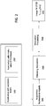
- Fig. 2 is a flow diagram of a first embodiment of the method for increasing the optical resolution of a STED microscope.
- the method is performed automatically.
- a sample is illuminated with either a pulsed or continuous excitation light beam with constant excitation intensity, in order to excite fluorophores in the sample.
- an image function F F(x,y) which is expressed as the convolution of a distribution of a sample object ⁇ (x',y') and a point spread function, (PSF, Point Spread Function ) of the microscope.
- F F(x,y)
- PSF Point Spread Function
- the modulation of the image function F is then obtained by the modulation of I STED (t) for each pixel.
- m ( x,y ) contains sub-diffractive information on the distribution of the object ⁇ (x, y) in the vicinity of the position (x,y).
- the multiplication factor ⁇ (I STED (t) / I sat ) is a function of the modulation of the intensity of I STED (t) of the STED beam.
- M(x,y) one fraction f center (x,y) of intensity of the fluorescence signal, corresponding to the contribution to the fluorescence signal coming from the fluorophores at the centre of the observation volume, is calculated.
- the values of constants M center and M periph are determined as follows.
- the value of M center corresponds to the minimum modulation value measured in the sample to the given experimental conditions.
- the value of Mcenter corresponds to the minimum modulation value for which the number of pixels is greater than or equal to a percentage ⁇ , optionally equal to 10%, of the peak value of the histogram of of M(x,y) values.
- M periph M center + ⁇ 2 / 2 ⁇ 1 ⁇ ⁇ 2 wherein ⁇ 1 and ⁇ 2 are the values of the standard deviation of the bi-dimensional gaussian distribution approximating a bi-dimensional histogram of g(x,y) and s(x,y) values.
- the values of constants M center and M periph can be determined by using a known sample of fluorescent beads and evaluating the quality of the images obtained at different values of M center and M periph .
- Figure 7 illustrates some processing of data obtained in a first simulated experiment, corresponding to a first experiment carried out with the first preferred embodiment described above of the method according to the invention. Said first experiment will be described in detail below with reference to figure 3 .
- Figure 7a shows the histogram of the measured M(x,y) values from which M center is obtained
- Figure 7b shows the g(x,y) and s(x,y) values that are approximated with a bi-dimensional Gaussian distribution shown in figure 7c , whose standard deviation values are used for the calculation of M periph .
- F m ⁇ STED x y f center x y F ′ STED x y wherein the subscript "m-STED” indicates the STED technique with modulation of the intensity of the STED beam.
- the STED image F' STED (x,y) used to generate the image F M-STED (x,y) can be chosen between an image averaged in time ⁇ F t-STED (x,y,t)> and any image of the temporal series F t-STED (x,y,t).
- acoustic-optical modulators AOM, acoustic-optical modulator
- AOM acoustic-optical modulator
- EOM Electro-optic modulator
- I STED t I max t T
- the time window T coincides with the typical time of integration of intensity in a pixel of a confocal or STED microscope (pixel dwell time), whose values are equal to about 10 ⁇ s up to about 100 ⁇ s.
- the linear ramp temporal pattern has the advantage of making the analysis of the signal in the time domain more direct.
- the modulation 200 of the STED beam is obtained with different temporal pattern, such as sinusoidal patterns.
- a series of images of fluorescence are acquired, i.e. are scanned, corresponding to the image function F t-STED (x,y,t) of Eq. 4, having increasing spatial resolution whereby the image at time T has the higher spatial resolution.
- the acquisition, i.e. the scanning, 300 of the fluorescence signal is solved in time and synchronised with the modulation of the STED beam.
- the modulation period equal to T and the number of acquired time instants equal to n being set
- the required temporal resolution is T / n.
- the timed acquisition must be synchronized with the scanning parameters.
- T coincides with the dwell time per total pixel.
- the synchronization can be performed even with other parameters, for example with the line scan time. In this latter case, the scanning of a horizontal line in a given vertical position is performed consecutively for n times, using a different intensity level at each scan, and then it goes to a line on a different vertical position.
- n fluorescence intensity values are associated with each pixel, which values will be processed in a step 400 to obtain the modulation M (x, y) of the image on each pixel given by Eq. 7.
- the intensity fluorescence values are processed to also calculate an averaged in time image ⁇ F t-STED (x,y,t)>.
- the modulation M of the image is obtained, in a step 500 the contribution f center (x,y) to fluorescence, given by fluorophores positioned at the center of the observation volume, is calculated, whereby the fraction is obtained.
- (x',y') corresponds to the distance from the center of a given pixel (x,y), whereby one more fluorophores can contribute to the fluorescence signal measured in a single pixel F(x,y).
- Equation 14 also shows that a spatial distribution of the depletion decay rate ⁇ dep ⁇ 1 x ′ , y ′ is provided determined by the spatial distribution of h STED (x',y').
- h STED (x',y') has a donut shape
- the signal from the fluorophores located at the periphery of the observation volume (maximum values of h STED ) will decay more quickly while the signal from the center of the observation volume (values close to zero of h STED ) will remain approximately constant, as schematically shown in the graph of Figure 1b .
- the signal of the fluorophores located on the periphery of the observation volume will be modulated while the signal from the center of the observation volume will not be modulated. This modulation gradient between the center and the periphery of the volume is used to separate from the total signal, the signal coming from the center.
- the separation at step 500 is performed with the same formalism used in the SPLIT technique, with the difference that the period T is not determined by the fluorescence decay of the fluorophores in the order of nanoseconds, but rather it is arbitrarily selected by setting the period T of the ramp (T> 100ns).
- T the period of the ramp
- I max must be of the magnitude order of I sat .
- Figure 3 shows the results of a first experiment simulated by the inventors who have applied a first preferred embodiment of the method of the present invention.
- the first simulated experiment consisted in having randomly located punctiform fluorophores in a sample and simulating an acquisition according to the first embodiment of the method with a modulation of the intensity of the STED beam in the time domain.
- the donut shape h STED (x',y') is simulated with a parabolic approximation h STED (x'y') ⁇ 2r 2 / w 0 2 .
- a sample is illuminated in step 100 with constant excitation intensity and is illuminated in step 200 with a modulated STED intensity with a linear ramp changing the STED intensity from value 0 to value I max in the time window T, shown in Figure 3a.
- the modulation M of the image at step 500 through equation 8, which allows to calculate f center (x,y) described above, the contribution of the fluorophores located at the center of the observation volume, shown in the image of Figure 3e , is separated from the contribution of those situated at the periphery, whose fluorescence image is shown in figure 3f .
- m-STED which is that of Figure 3e given by the contribution of the fluorescence of the fluorophores at the center, has a higher resolution than the STED image with the maximum resolution of Figure 3d , as shown by a comparison of the line profiles shown in Figure 3g (wherein it is also reported that obtained with confocal microscopy without STED technique).
- the fluorescence signal f(x', y', t) is phase shifted with respect to a signal of the STED beam and will contain the main frequency ⁇ and the higher harmonics due to the non-linearity of the exponential factor.
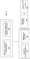
- the modulation M of the image can be obtained by analysing the fluorescence signal at a frequency ⁇ or at higher frequencies. This can be done via a suitable hardware setting, wherein an analysis instrument acquires in a step 300' fluorescence signals from a sample and directly outputs, in a step 400', the values of the average intensity ⁇ F t-STED (x , y, t)> and of the modulation M ⁇ (x,y) of the fluorescence signal.
- a suitable hardware setting can be for example a standard lock-in detecting apparatus at frequency ⁇ , wherein a lock-in amplifier directly provides, in addition to the average value of intensity ⁇ F t-STED (x,y,t)>, the modulation values M ⁇ (x,y) and phase ⁇ ⁇ (x,y) during an acquisition 300' of fluorescence signals.
- step 400 for calculating the modulation M(x,y) of the image to obtain the final image F M-STED ( x,y ) at higher resolution is not necessary.
- K corresponds to a constant having a positive value M periph above defined between 0 and 1.
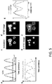
- Figure 5 shows the results of a second experiment simulated by the inventors who have applied a second preferred embodiment of the method.
- the second simulated experiment consisted in using the same sample of the first experiment, i.e. with randomly located punctiform fluorophores, and simulating an acquisition according to the second embodiment of the method with a modulation of the intensity of the STED beam in the frequency domain.
- the results of which are shown schematically in Figure 3
- the simulated image is 32x32 pixels
- the pixel size is 20nm
- the value of w 0 160nm
- the value of I max / Isat 4
- a sample is illuminated at step 100 with constant excitation intensity and is illuminated at step 200' with a STED intensity modulated with a sine wave at a frequency ⁇ , shown in Figure 5a .
- STED images are acquired, with detection techniques in lock-in at frequency ⁇ , whereby the fluorescence signal is modulated and phase shifted, with the highest modulation at the periphery of the observation volume as schematically shown in Figure 5b .
- Eq. 10' the contribution of the fluorophores located at the center of the observation volume, shown in the image of Figure 5e , is separated from the contribution of those situated at the periphery, whose fluorescence image is shown in figure 5f .
- m-STED which is that of Figure 5e given by the contribution of the fluorescence of the fluorophores at the center, has a higher resolution than the STED image with the maximum resolution of Figure 5d , as shown by a comparison of the line profiles shown in Figure 5g .
- the authors have also performed experimental tests on fluorescent beads analysed with a STED microscopy apparatus integrated with the first preferred embodiment of the method. Some experimental results are reported in Figure 6 .
- the experiment was performed with a standard STED apparatus on a sample of fluorescent beads of about 40nm in size.
- the intensity of the STED beam was modulated (step 200) with an AOM driven in such a way as to generate a linear ramp, from a value 0 to a value I max , shown in Figure 6a .
- These series of images were subsequently processed (step 400) to obtain an image modulation M shown in Figure 6c.
- Figure 6d shows the STED image of fluorescence at maximum resolution.
Landscapes
- Physics & Mathematics (AREA)
- Health & Medical Sciences (AREA)
- Chemical & Material Sciences (AREA)
- Analytical Chemistry (AREA)
- General Physics & Mathematics (AREA)
- Life Sciences & Earth Sciences (AREA)
- Engineering & Computer Science (AREA)
- Immunology (AREA)
- Nuclear Medicine, Radiotherapy & Molecular Imaging (AREA)
- Biochemistry (AREA)
- General Health & Medical Sciences (AREA)
- Pathology (AREA)
- Optics & Photonics (AREA)
- Computer Vision & Pattern Recognition (AREA)
- Multimedia (AREA)
- General Engineering & Computer Science (AREA)
- Biomedical Technology (AREA)
- Molecular Biology (AREA)
- Investigating, Analyzing Materials By Fluorescence Or Luminescence (AREA)
- Microscoopes, Condenser (AREA)
Claims (8)
- Verfahren zur modulierten Stimulated-Emission-Depletion-Mikroskopie mit hoher räumlicher Auflösung (STED-Mikroskopie), welches die folgenden Schritte umfasst:A. Anstrahlen (100) einer Probe, welche ein oder mehrere Fluorophore in einem Beobachtungsvolumen enthält, mit einem Anregungslichtstrahl mit einer konstanten Anregungsintensität, um das eine oder die mehreren Fluorophore in der Probe anzuregen;B. Anstrahlen (200, 200') der Probe mit einem Donut-geformten Lichtstrahl, um durch stimulierte Emission das eine oder die mehreren angeregten Fluorophore zum Erhalten eines tatsächlichen Beobachtungsvolumens abzuregen, wobei der Abregungslichtstrahl eine Intensität ISTED aufweist, welche mit einem zeitlichen Muster mit einer Modulationsperiode T zeitlich moduliert ist ISTED = ISTED (t);C. Erfassen (300, 300') eines oder mehrerer von der Probe emittierter Fluoreszenzsignale auf einer Bildebene (x, y) von Pixeln;D. Erhalten (400, 400') einer Bildmodulation M(x,y) der Probe auf der Bildebene (x, y) von Pixeln, welche sich aus der Modulation der Intensität ISTED (t) des Abregungsstrahls für jeden Pixel (x, y) ergibt, auf der Grundlage des einen oder der mehreren Fluoreszenzsignale, die in Schritt C erfasst wurden;E. Verarbeiten (500, 500') der Bildmodulation M(x, y), um einen Anteil fcenter(x, y) einer Fluoreszenzintensität auf der Bildebene (x, y) von Pixeln zu erhalten, welcher einem Beitrag zu dem einen oder den mehreren Fluoreszenzsignalen entspricht, die in Schritt C erfasst wurden, und welcher von Fluorophoren stammt, welche in einem Zentrum des tatsächlichen Beobachtungsvolumens der Probe vorliegen;F. Berechnen (600, 600') eines endgültigen Bildes FM-STED(x, y) der Probe auf der Bildebene (x, y) von Pixeln aus dem einen oder den mehreren Fluoreszenzsignalen, die in Schritt C erfasst wurden, und aus der in Schritt D erhaltenen Bildmodulationsfunktion M(x, y), wie folgt:

- Verfahren nach Anspruch 1, dadurch gekennzeichnet, dass Schritt C das Erfassen einer Zeitreihe von Fluoreszenzbildern Ft-STED (x,y,t) umfasst, wobei Schritt D die Berechnung der Bildmodulation M(x,y) aus Abweichungen |δFt-STED(x,y,t)/ft-STED(x,y,t)| einer Intensität der erfassten Fluoreszenzbilder Ft-STED(x,y,t) umfasst.
- Verfahren nach Anspruch 1 oder 2, dadurch gekennzeichnet, dass Schritt C durch Abtasten eines xy-Bereichs der Probe synchronisiert mit der Modulationsperiode T durchgeführt wird, wobei, wenn eine Anzahl erfasster Zeitpunkte gleich n gesetzt wird, die erforderliche zeitliche Auflösung der Abtastung T/n beträgt.
- Verfahren nach Anspruch 3, dadurch gekennzeichnet, dass T einer Verweilzeit pro gesamtem Pixel entspricht.
- Verfahren nach Anspruch 3 oder 4, dadurch gekennzeichnet, dass T/n einer Linienabtastzeit entspricht und n aufeinanderfolgende Linien bei verschiedener STED Leistung erfasst werden.
- Verfahren nach einer der vorhergehenden Ansprüche 3 bis 5, dadurch gekennzeichnet, dass das zeitliche Muster von ISTED ein lineares Muster mit einer Periode von T>>1 ns aufweist, optional zwischen 10 µs und 100 µs, und noch optionaler gleich 50 µs.
- Verfahren nach Anspruch 1, dadurch gekennzeichnet, dass die Intensität ISTED mit einer Frequenz ω moduliert wird und dass Schritt C eine Frequenzerfassung von Fluoreszenzsignalen über eine Lock-in Erfassung und eine Analysevorrichtung umfasst, welche Schritt D direkt implementiert, wobei als Ausgabe eine Modulation Mω(x,y) bereitgestellt wird und wobei ferner ein zeitlich gemitteltes Ausgabefluoreszenzbild <Ft-STED(x,y,t)> bereitgestellt wird, wobei das endgültige Bild FM-STED(x,y) der Probe in Schritt F nach:

- Verfahren nach Anspruch 7, dadurch gekennzeichnet, dass das zeitliche Muster von ISTED ein sinusförmiges Muster mit einer Frequenz von ω/2π << 1 GHz aufweist, optional zwischen 10 kHz und 1 MHz, und noch optionaler gleich 100kHz.
Applications Claiming Priority (2)
| Application Number | Priority Date | Filing Date | Title |
|---|---|---|---|
| IT102017000118432A IT201700118432A1 (it) | 2017-10-19 | 2017-10-19 | Metodo di microscopia a deplezione mediante emissione stimolata ad alta risoluzione spaziale |
| PCT/IB2018/058123 WO2019077556A1 (en) | 2017-10-19 | 2018-10-19 | STIMULATED EMITTING MICROSCOPY METHOD (STED) WITH HIGH SPACE RESOLUTION |
Publications (2)
| Publication Number | Publication Date |
|---|---|
| EP3698124A1 EP3698124A1 (de) | 2020-08-26 |
| EP3698124B1 true EP3698124B1 (de) | 2021-07-07 |
Family
ID=61224389
Family Applications (1)
| Application Number | Title | Priority Date | Filing Date |
|---|---|---|---|
| EP18815011.4A Active EP3698124B1 (de) | 2017-10-19 | 2018-10-19 | Verfahren zur stimulated-emission-depletion-mikroskopie mit hoher räumlicher auflösung |
Country Status (4)
| Country | Link |
|---|---|
| US (1) | US11372224B2 (de) |
| EP (1) | EP3698124B1 (de) |
| IT (1) | IT201700118432A1 (de) |
| WO (1) | WO2019077556A1 (de) |
Families Citing this family (5)
| Publication number | Priority date | Publication date | Assignee | Title |
|---|---|---|---|---|
| CN111474150B (zh) * | 2020-04-08 | 2022-03-22 | 华南师范大学 | 一种sted超分辨图像背景噪声差分抑制方法 |
| CN111521596B (zh) * | 2020-06-04 | 2021-02-05 | 深圳大学 | 荧光差分超分辨成像方法及成像系统 |
| CN111982870B (zh) | 2020-08-07 | 2023-04-28 | 深圳大学 | 一种扫描结构光超分辨显微成像装置及方法 |
| EP4166930A1 (de) | 2021-10-15 | 2023-04-19 | Abberior Instruments GmbH | Verfahren, vorrichtung, mikroskop und computerprogramm zur analyse von mikroskopiedaten |
| CN114216887B (zh) * | 2021-12-02 | 2023-11-28 | 南昌大学 | 偏振调制提高受激发射损耗显微系统分辨率的方法 |
Family Cites Families (2)
| Publication number | Priority date | Publication date | Assignee | Title |
|---|---|---|---|---|
| DE102006046369A1 (de) * | 2006-09-29 | 2008-04-03 | Carl Zeiss Microimaging Gmbh | Auflösungsgesteigerte Lumineszenzmikroskopie |
| ITTO20130692A1 (it) | 2013-08-13 | 2015-02-14 | Fond Istituto Italiano Di Tecnologia | Microscopia a deplezione mediante emissione stimolata (sted), con gating temporale del fascio di eccitazione e rilevamento sincrono dell'emissione di fluorescenza |
-
2017
- 2017-10-19 IT IT102017000118432A patent/IT201700118432A1/it unknown
-
2018
- 2018-10-19 EP EP18815011.4A patent/EP3698124B1/de active Active
- 2018-10-19 US US16/756,281 patent/US11372224B2/en active Active
- 2018-10-19 WO PCT/IB2018/058123 patent/WO2019077556A1/en not_active Ceased
Also Published As
| Publication number | Publication date |
|---|---|
| EP3698124A1 (de) | 2020-08-26 |
| US11372224B2 (en) | 2022-06-28 |
| WO2019077556A1 (en) | 2019-04-25 |
| US20200333573A1 (en) | 2020-10-22 |
| IT201700118432A1 (it) | 2019-04-19 |
Similar Documents
| Publication | Publication Date | Title |
|---|---|---|
| US11372224B2 (en) | Method of stimulated emission depletion microscopy having high spatial resolution | |
| US9001321B2 (en) | Microscope and observation method | |
| US10409047B2 (en) | High frame-rate multichannel beam-scanning microscopy | |
| Futia et al. | Spatially-chirped modulation imaging of absorbtion and fluorescent objects on single-element optical detector | |
| JP6260691B2 (ja) | 構造化照明顕微鏡装置及び構造化照明観察方法 | |
| US20200386974A1 (en) | Time-resolved imaging method with high spatial resolution | |
| EP3685205A1 (de) | Abbildung einer probe durch ein streuungsmedium | |
| KR101847334B1 (ko) | 형광 이미지 획득 장치 및 방법 | |
| Ramachandran et al. | Two-dimensional imaging through turbid media using a continuous wave light source | |
| Zada et al. | Stimulated Raman scattering simulation for imaging optimization | |
| JP2003255231A (ja) | 光イメージングシステム及び光イメージのデータ処理方法 | |
| JP7085989B2 (ja) | Srsイメージングのための動的なロックイン検出帯域幅 | |
| CN109916867B (zh) | 荧光强度相关时间分辨增强成像方法及装置 | |
| JP2018531424A6 (ja) | Srsイメージングのための動的なロックイン検出帯域幅 | |
| JP2010039323A (ja) | 共焦点顕微鏡 | |
| US12055490B2 (en) | Method of measuring diffusion in a medium | |
| Chen et al. | Elimination of Re‐excitation in Stimulated Emission Depletion Nanoscopy Based on Photon Extraction in a Phasor Plot | |
| JP7465512B2 (ja) | 光学顕微鏡、及び撮像方法 | |
| Sung et al. | Fast three‐dimensional chemical imaging by interferometric multiplex coherent anti‐Stokes Raman scattering microscopy | |
| Makrushin et al. | Capturing latent fingerprints from metallic painted surfaces using UV-VIS spectroscope | |
| JP7577388B2 (ja) | Carsスペクトルを取得するための方法およびシステム | |
| US20120193552A1 (en) | Fluorescence lifetime imaging | |
| Liron et al. | Stimulated Raman scattering simulation for imaging optimization | |
| Qu et al. | Fluorescence lifetime imaging microscopy based on a synchroscan streak camera | |
| KR20160039931A (ko) | 테라헤르츠 전자기파를 이용하는 이미징 장치 및 방법 |
Legal Events
| Date | Code | Title | Description |
|---|---|---|---|
| STAA | Information on the status of an ep patent application or granted ep patent |
Free format text: STATUS: UNKNOWN |
|
| STAA | Information on the status of an ep patent application or granted ep patent |
Free format text: STATUS: THE INTERNATIONAL PUBLICATION HAS BEEN MADE |
|
| PUAI | Public reference made under article 153(3) epc to a published international application that has entered the european phase |
Free format text: ORIGINAL CODE: 0009012 |
|
| STAA | Information on the status of an ep patent application or granted ep patent |
Free format text: STATUS: REQUEST FOR EXAMINATION WAS MADE |
|
| 17P | Request for examination filed |
Effective date: 20200512 |
|
| AK | Designated contracting states |
Kind code of ref document: A1 Designated state(s): AL AT BE BG CH CY CZ DE DK EE ES FI FR GB GR HR HU IE IS IT LI LT LU LV MC MK MT NL NO PL PT RO RS SE SI SK SM TR |
|
| AX | Request for extension of the european patent |
Extension state: BA ME |
|
| DAV | Request for validation of the european patent (deleted) | ||
| DAX | Request for extension of the european patent (deleted) | ||
| GRAP | Despatch of communication of intention to grant a patent |
Free format text: ORIGINAL CODE: EPIDOSNIGR1 |
|
| STAA | Information on the status of an ep patent application or granted ep patent |
Free format text: STATUS: GRANT OF PATENT IS INTENDED |
|
| INTG | Intention to grant announced |
Effective date: 20210222 |
|
| GRAS | Grant fee paid |
Free format text: ORIGINAL CODE: EPIDOSNIGR3 |
|
| GRAA | (expected) grant |
Free format text: ORIGINAL CODE: 0009210 |
|
| STAA | Information on the status of an ep patent application or granted ep patent |
Free format text: STATUS: THE PATENT HAS BEEN GRANTED |
|
| AK | Designated contracting states |
Kind code of ref document: B1 Designated state(s): AL AT BE BG CH CY CZ DE DK EE ES FI FR GB GR HR HU IE IS IT LI LT LU LV MC MK MT NL NO PL PT RO RS SE SI SK SM TR |
|
| REG | Reference to a national code |
Ref country code: GB Ref legal event code: FG4D |
|
| REG | Reference to a national code |
Ref country code: AT Ref legal event code: REF Ref document number: 1409066 Country of ref document: AT Kind code of ref document: T Effective date: 20210715 |
|
| REG | Reference to a national code |
Ref country code: DE Ref legal event code: R096 Ref document number: 602018019884 Country of ref document: DE |
|
| REG | Reference to a national code |
Ref country code: IE Ref legal event code: FG4D |
|
| REG | Reference to a national code |
Ref country code: LT Ref legal event code: MG9D |
|
| REG | Reference to a national code |
Ref country code: NL Ref legal event code: MP Effective date: 20210707 |
|
| REG | Reference to a national code |
Ref country code: AT Ref legal event code: MK05 Ref document number: 1409066 Country of ref document: AT Kind code of ref document: T Effective date: 20210707 |
|
| PG25 | Lapsed in a contracting state [announced via postgrant information from national office to epo] |
Ref country code: NL Free format text: LAPSE BECAUSE OF FAILURE TO SUBMIT A TRANSLATION OF THE DESCRIPTION OR TO PAY THE FEE WITHIN THE PRESCRIBED TIME-LIMIT Effective date: 20210707 Ref country code: PT Free format text: LAPSE BECAUSE OF FAILURE TO SUBMIT A TRANSLATION OF THE DESCRIPTION OR TO PAY THE FEE WITHIN THE PRESCRIBED TIME-LIMIT Effective date: 20211108 Ref country code: NO Free format text: LAPSE BECAUSE OF FAILURE TO SUBMIT A TRANSLATION OF THE DESCRIPTION OR TO PAY THE FEE WITHIN THE PRESCRIBED TIME-LIMIT Effective date: 20211007 Ref country code: HR Free format text: LAPSE BECAUSE OF FAILURE TO SUBMIT A TRANSLATION OF THE DESCRIPTION OR TO PAY THE FEE WITHIN THE PRESCRIBED TIME-LIMIT Effective date: 20210707 Ref country code: BG Free format text: LAPSE BECAUSE OF FAILURE TO SUBMIT A TRANSLATION OF THE DESCRIPTION OR TO PAY THE FEE WITHIN THE PRESCRIBED TIME-LIMIT Effective date: 20211007 Ref country code: AT Free format text: LAPSE BECAUSE OF FAILURE TO SUBMIT A TRANSLATION OF THE DESCRIPTION OR TO PAY THE FEE WITHIN THE PRESCRIBED TIME-LIMIT Effective date: 20210707 Ref country code: LT Free format text: LAPSE BECAUSE OF FAILURE TO SUBMIT A TRANSLATION OF THE DESCRIPTION OR TO PAY THE FEE WITHIN THE PRESCRIBED TIME-LIMIT Effective date: 20210707 Ref country code: RS Free format text: LAPSE BECAUSE OF FAILURE TO SUBMIT A TRANSLATION OF THE DESCRIPTION OR TO PAY THE FEE WITHIN THE PRESCRIBED TIME-LIMIT Effective date: 20210707 Ref country code: SE Free format text: LAPSE BECAUSE OF FAILURE TO SUBMIT A TRANSLATION OF THE DESCRIPTION OR TO PAY THE FEE WITHIN THE PRESCRIBED TIME-LIMIT Effective date: 20210707 Ref country code: FI Free format text: LAPSE BECAUSE OF FAILURE TO SUBMIT A TRANSLATION OF THE DESCRIPTION OR TO PAY THE FEE WITHIN THE PRESCRIBED TIME-LIMIT Effective date: 20210707 Ref country code: ES Free format text: LAPSE BECAUSE OF FAILURE TO SUBMIT A TRANSLATION OF THE DESCRIPTION OR TO PAY THE FEE WITHIN THE PRESCRIBED TIME-LIMIT Effective date: 20210707 |
|
| PG25 | Lapsed in a contracting state [announced via postgrant information from national office to epo] |
Ref country code: PL Free format text: LAPSE BECAUSE OF FAILURE TO SUBMIT A TRANSLATION OF THE DESCRIPTION OR TO PAY THE FEE WITHIN THE PRESCRIBED TIME-LIMIT Effective date: 20210707 Ref country code: LV Free format text: LAPSE BECAUSE OF FAILURE TO SUBMIT A TRANSLATION OF THE DESCRIPTION OR TO PAY THE FEE WITHIN THE PRESCRIBED TIME-LIMIT Effective date: 20210707 Ref country code: GR Free format text: LAPSE BECAUSE OF FAILURE TO SUBMIT A TRANSLATION OF THE DESCRIPTION OR TO PAY THE FEE WITHIN THE PRESCRIBED TIME-LIMIT Effective date: 20211008 |
|
| REG | Reference to a national code |
Ref country code: DE Ref legal event code: R097 Ref document number: 602018019884 Country of ref document: DE |
|
| PG25 | Lapsed in a contracting state [announced via postgrant information from national office to epo] |
Ref country code: DK Free format text: LAPSE BECAUSE OF FAILURE TO SUBMIT A TRANSLATION OF THE DESCRIPTION OR TO PAY THE FEE WITHIN THE PRESCRIBED TIME-LIMIT Effective date: 20210707 |
|
| PLBE | No opposition filed within time limit |
Free format text: ORIGINAL CODE: 0009261 |
|
| STAA | Information on the status of an ep patent application or granted ep patent |
Free format text: STATUS: NO OPPOSITION FILED WITHIN TIME LIMIT |
|
| REG | Reference to a national code |
Ref country code: CH Ref legal event code: PL |
|
| PG25 | Lapsed in a contracting state [announced via postgrant information from national office to epo] |
Ref country code: SM Free format text: LAPSE BECAUSE OF FAILURE TO SUBMIT A TRANSLATION OF THE DESCRIPTION OR TO PAY THE FEE WITHIN THE PRESCRIBED TIME-LIMIT Effective date: 20210707 Ref country code: SK Free format text: LAPSE BECAUSE OF FAILURE TO SUBMIT A TRANSLATION OF THE DESCRIPTION OR TO PAY THE FEE WITHIN THE PRESCRIBED TIME-LIMIT Effective date: 20210707 Ref country code: RO Free format text: LAPSE BECAUSE OF FAILURE TO SUBMIT A TRANSLATION OF THE DESCRIPTION OR TO PAY THE FEE WITHIN THE PRESCRIBED TIME-LIMIT Effective date: 20210707 Ref country code: EE Free format text: LAPSE BECAUSE OF FAILURE TO SUBMIT A TRANSLATION OF THE DESCRIPTION OR TO PAY THE FEE WITHIN THE PRESCRIBED TIME-LIMIT Effective date: 20210707 Ref country code: CZ Free format text: LAPSE BECAUSE OF FAILURE TO SUBMIT A TRANSLATION OF THE DESCRIPTION OR TO PAY THE FEE WITHIN THE PRESCRIBED TIME-LIMIT Effective date: 20210707 Ref country code: AL Free format text: LAPSE BECAUSE OF FAILURE TO SUBMIT A TRANSLATION OF THE DESCRIPTION OR TO PAY THE FEE WITHIN THE PRESCRIBED TIME-LIMIT Effective date: 20210707 |
|
| 26N | No opposition filed |
Effective date: 20220408 |
|
| REG | Reference to a national code |
Ref country code: BE Ref legal event code: MM Effective date: 20211031 |
|
| PG25 | Lapsed in a contracting state [announced via postgrant information from national office to epo] |
Ref country code: MC Free format text: LAPSE BECAUSE OF FAILURE TO SUBMIT A TRANSLATION OF THE DESCRIPTION OR TO PAY THE FEE WITHIN THE PRESCRIBED TIME-LIMIT Effective date: 20210707 |
|
| PG25 | Lapsed in a contracting state [announced via postgrant information from national office to epo] |
Ref country code: LU Free format text: LAPSE BECAUSE OF NON-PAYMENT OF DUE FEES Effective date: 20211019 Ref country code: BE Free format text: LAPSE BECAUSE OF NON-PAYMENT OF DUE FEES Effective date: 20211031 |
|
| PG25 | Lapsed in a contracting state [announced via postgrant information from national office to epo] |
Ref country code: LI Free format text: LAPSE BECAUSE OF NON-PAYMENT OF DUE FEES Effective date: 20211031 Ref country code: CH Free format text: LAPSE BECAUSE OF NON-PAYMENT OF DUE FEES Effective date: 20211031 |
|
| PG25 | Lapsed in a contracting state [announced via postgrant information from national office to epo] |
Ref country code: IE Free format text: LAPSE BECAUSE OF NON-PAYMENT OF DUE FEES Effective date: 20211019 |
|
| PG25 | Lapsed in a contracting state [announced via postgrant information from national office to epo] |
Ref country code: CY Free format text: LAPSE BECAUSE OF FAILURE TO SUBMIT A TRANSLATION OF THE DESCRIPTION OR TO PAY THE FEE WITHIN THE PRESCRIBED TIME-LIMIT Effective date: 20210707 |
|
| PG25 | Lapsed in a contracting state [announced via postgrant information from national office to epo] |
Ref country code: HU Free format text: LAPSE BECAUSE OF FAILURE TO SUBMIT A TRANSLATION OF THE DESCRIPTION OR TO PAY THE FEE WITHIN THE PRESCRIBED TIME-LIMIT; INVALID AB INITIO Effective date: 20181019 |
|
| PG25 | Lapsed in a contracting state [announced via postgrant information from national office to epo] |
Ref country code: MK Free format text: LAPSE BECAUSE OF FAILURE TO SUBMIT A TRANSLATION OF THE DESCRIPTION OR TO PAY THE FEE WITHIN THE PRESCRIBED TIME-LIMIT Effective date: 20210707 |
|
| PG25 | Lapsed in a contracting state [announced via postgrant information from national office to epo] |
Ref country code: MT Free format text: LAPSE BECAUSE OF FAILURE TO SUBMIT A TRANSLATION OF THE DESCRIPTION OR TO PAY THE FEE WITHIN THE PRESCRIBED TIME-LIMIT Effective date: 20210707 |
|
| PG25 | Lapsed in a contracting state [announced via postgrant information from national office to epo] |
Ref country code: TR Free format text: LAPSE BECAUSE OF FAILURE TO SUBMIT A TRANSLATION OF THE DESCRIPTION OR TO PAY THE FEE WITHIN THE PRESCRIBED TIME-LIMIT Effective date: 20210707 |
|
| PGFP | Annual fee paid to national office [announced via postgrant information from national office to epo] |
Ref country code: DE Payment date: 20251010 Year of fee payment: 8 |
|
| PGFP | Annual fee paid to national office [announced via postgrant information from national office to epo] |
Ref country code: GB Payment date: 20251009 Year of fee payment: 8 |
|
| PGFP | Annual fee paid to national office [announced via postgrant information from national office to epo] |
Ref country code: IT Payment date: 20251014 Year of fee payment: 8 |
|
| PGFP | Annual fee paid to national office [announced via postgrant information from national office to epo] |
Ref country code: FR Payment date: 20251009 Year of fee payment: 8 |