EP3698003B1 - Acoustic shutter assembly - Google Patents
Acoustic shutter assembly Download PDFInfo
- Publication number
- EP3698003B1 EP3698003B1 EP18793187.8A EP18793187A EP3698003B1 EP 3698003 B1 EP3698003 B1 EP 3698003B1 EP 18793187 A EP18793187 A EP 18793187A EP 3698003 B1 EP3698003 B1 EP 3698003B1
- Authority
- EP
- European Patent Office
- Prior art keywords
- sound absorbing
- absorbing material
- acoustic
- layer
- shutter assembly
- Prior art date
- Legal status (The legal status is an assumption and is not a legal conclusion. Google has not performed a legal analysis and makes no representation as to the accuracy of the status listed.)
- Active
Links
- 238000009423 ventilation Methods 0.000 claims description 83
- 239000011358 absorbing material Substances 0.000 claims description 59
- 238000010521 absorption reaction Methods 0.000 claims description 24
- 239000000463 material Substances 0.000 claims description 6
- 230000000903 blocking effect Effects 0.000 claims description 3
- 239000002184 metal Substances 0.000 description 6
- 238000009413 insulation Methods 0.000 description 3
- 230000004888 barrier function Effects 0.000 description 2
- 239000000428 dust Substances 0.000 description 2
- 210000003027 ear inner Anatomy 0.000 description 2
- 239000011888 foil Substances 0.000 description 2
- 229920000139 polyethylene terephthalate Polymers 0.000 description 2
- 239000005020 polyethylene terephthalate Substances 0.000 description 2
- 241000238631 Hexapoda Species 0.000 description 1
- -1 Polyethylene terephthalate Polymers 0.000 description 1
- 239000003638 chemical reducing agent Substances 0.000 description 1
- 239000011521 glass Substances 0.000 description 1
- 239000002245 particle Substances 0.000 description 1
- 238000005096 rolling process Methods 0.000 description 1
- 238000005476 soldering Methods 0.000 description 1
- 238000003466 welding Methods 0.000 description 1
Images


Classifications
-
- E—FIXED CONSTRUCTIONS
- E06—DOORS, WINDOWS, SHUTTERS, OR ROLLER BLINDS IN GENERAL; LADDERS
- E06B—FIXED OR MOVABLE CLOSURES FOR OPENINGS IN BUILDINGS, VEHICLES, FENCES OR LIKE ENCLOSURES IN GENERAL, e.g. DOORS, WINDOWS, BLINDS, GATES
- E06B9/00—Screening or protective devices for wall or similar openings, with or without operating or securing mechanisms; Closures of similar construction
- E06B9/02—Shutters, movable grilles, or other safety closing devices, e.g. against burglary
- E06B9/04—Shutters, movable grilles, or other safety closing devices, e.g. against burglary of wing type, e.g. revolving or sliding
-
- E—FIXED CONSTRUCTIONS
- E06—DOORS, WINDOWS, SHUTTERS, OR ROLLER BLINDS IN GENERAL; LADDERS
- E06B—FIXED OR MOVABLE CLOSURES FOR OPENINGS IN BUILDINGS, VEHICLES, FENCES OR LIKE ENCLOSURES IN GENERAL, e.g. DOORS, WINDOWS, BLINDS, GATES
- E06B5/00—Doors, windows, or like closures for special purposes; Border constructions therefor
- E06B5/20—Doors, windows, or like closures for special purposes; Border constructions therefor for insulation against noise
-
- E—FIXED CONSTRUCTIONS
- E06—DOORS, WINDOWS, SHUTTERS, OR ROLLER BLINDS IN GENERAL; LADDERS
- E06B—FIXED OR MOVABLE CLOSURES FOR OPENINGS IN BUILDINGS, VEHICLES, FENCES OR LIKE ENCLOSURES IN GENERAL, e.g. DOORS, WINDOWS, BLINDS, GATES
- E06B7/00—Special arrangements or measures in connection with doors or windows
- E06B7/02—Special arrangements or measures in connection with doors or windows for providing ventilation, e.g. through double windows; Arrangement of ventilation roses
- E06B7/10—Special arrangements or measures in connection with doors or windows for providing ventilation, e.g. through double windows; Arrangement of ventilation roses by special construction of the frame members
-
- G—PHYSICS
- G10—MUSICAL INSTRUMENTS; ACOUSTICS
- G10K—SOUND-PRODUCING DEVICES; METHODS OR DEVICES FOR PROTECTING AGAINST, OR FOR DAMPING, NOISE OR OTHER ACOUSTIC WAVES IN GENERAL; ACOUSTICS NOT OTHERWISE PROVIDED FOR
- G10K11/00—Methods or devices for transmitting, conducting or directing sound in general; Methods or devices for protecting against, or for damping, noise or other acoustic waves in general
- G10K11/16—Methods or devices for protecting against, or for damping, noise or other acoustic waves in general
- G10K11/162—Selection of materials
- G10K11/168—Plural layers of different materials, e.g. sandwiches
-
- F—MECHANICAL ENGINEERING; LIGHTING; HEATING; WEAPONS; BLASTING
- F24—HEATING; RANGES; VENTILATING
- F24F—AIR-CONDITIONING; AIR-HUMIDIFICATION; VENTILATION; USE OF AIR CURRENTS FOR SCREENING
- F24F13/00—Details common to, or for air-conditioning, air-humidification, ventilation or use of air currents for screening
- F24F13/08—Air-flow control members, e.g. louvres, grilles, flaps or guide plates
- F24F13/18—Air-flow control members, e.g. louvres, grilles, flaps or guide plates specially adapted for insertion in flat panels, e.g. in door or window-pane
-
- F—MECHANICAL ENGINEERING; LIGHTING; HEATING; WEAPONS; BLASTING
- F24—HEATING; RANGES; VENTILATING
- F24F—AIR-CONDITIONING; AIR-HUMIDIFICATION; VENTILATION; USE OF AIR CURRENTS FOR SCREENING
- F24F13/00—Details common to, or for air-conditioning, air-humidification, ventilation or use of air currents for screening
- F24F13/24—Means for preventing or suppressing noise
-
- Y—GENERAL TAGGING OF NEW TECHNOLOGICAL DEVELOPMENTS; GENERAL TAGGING OF CROSS-SECTIONAL TECHNOLOGIES SPANNING OVER SEVERAL SECTIONS OF THE IPC; TECHNICAL SUBJECTS COVERED BY FORMER USPC CROSS-REFERENCE ART COLLECTIONS [XRACs] AND DIGESTS
- Y10—TECHNICAL SUBJECTS COVERED BY FORMER USPC
- Y10S—TECHNICAL SUBJECTS COVERED BY FORMER USPC CROSS-REFERENCE ART COLLECTIONS [XRACs] AND DIGESTS
- Y10S454/00—Ventilation
- Y10S454/906—Noise inhibiting means
Definitions
- the present invention relates to an acoustic shutter assembly adapted to cover a window opening in a wall, including at least one window pane arranged in a frame having an inside adapted to be mounted on the wall and an outside adapted to face away from the wall, wherein at least one ventilation duct is arranged in the frame between an outer ventilation opening and an inner ventilation opening, wherein the ventilation duct extends between a first layer of sound absorbing material arranged at the inside of the frame and a second layer of sound absorbing material arranged at the outside of the frame, and wherein the first and second layers of sound absorbing material extend at least substantially in parallel with the window pane.
- WO 2012/164349 discloses an acoustic shutter assembly, including at least one window pane arranged in a frame, wherein at least one ventilation duct is arranged in the frame between an outer ventilation opening and an inner ventilation opening.
- DE 296 08 765 U1 discloses a noise reducing window attachment to be mounted on the outside of an existing window.
- labyrinths are arranged at either side and at the top in order to reduce the entrance of traffic noise, but to allow air exchange. Sound insulation is provided at the bottom.
- this window attachment may reduce the entrance of traffic noise somewhat, in areas of heavy traffic, especially low frequency noise may still be a problem.
- CN104675287 A discloses a daylighting, ventilation and noise reduction window to be mounted on window openings.
- a ventilation noise reducer in the form of a simple labyrinth is arranged on the periphery of the glass window.
- an acoustic shutter assembly which is adapted to cover a window opening in a wall, and in which the ventilation air enters at either side through respective ducts formed between an outer and an inner layer of sound absorbing material.
- the object of the present invention is to provide an acoustic shutter assembly having improved soundproofing properties compared to known solutions, without compromising ventilation properties.
- a number of acoustic reflectors in the form of plate material are arranged between the first and second layers of sound absorbing material so that the ventilation duct is separated into a number of respective ventilation channels formed between the acoustic reflectors, and each ventilation channel changes direction at least once between the outer ventilation opening and the inner ventilation opening, thereby at least substantially blocking any linear path from the outer ventilation opening to the inner ventilation opening.
- the combination of the acoustic reflectors blocking any linear path from the outer ventilation opening to the inner ventilation opening and the first and second layer of sound absorbing material forming the ventilation duct may significantly reduce the noise entering through the acoustic shutter assembly without reducing the ventilation capabilities of the assembly.
- the ventilation duct is lined by means of a first perforated plate covering the first layer of sound absorbing material and a second perforated plate covering the second layer of sound absorbing material so that the acoustic reflectors extend from the first perforated plate to the second perforated plate.
- the perforated plate may serve to hold the sound absorbing material in place and provide a smooth surface of the inside of the ventilation duct, thereby ensuring free movement of ventilation air.
- the perforated plate may preferably be a metal plate and the acoustic reflectors may preferably be fixed to the perforated plates, preferably by welding or soldering, thereby providing increased stability and consequently better sound absorption.
- the first layer of sound absorbing material has a first thickness and the second layer of sound absorbing material has a second thickness, and the second thickness is greater than the first thickness.
- the relatively greater thickness of the second layer of sound absorbing material may ensure that low frequency noise is absorbed
- the relatively smaller thickness of the first layer of sound absorbing material may ensure that the total thickness of the first and second layers of sound absorbing material is relatively thin.
- the second thickness is at least 4/3 of, more preferred at least 3/2 of, and most preferred about the double of, the first thickness.
- each acoustic reflector is V-formed with a first leg extending obliquely towards the outer ventilation opening and a second leg extending obliquely towards the inner ventilation opening, and the first and second leg of each acoustic reflector preferably connect at least approximately midway between the outer ventilation opening and the inner ventilation opening in a top point of the acoustic reflector.
- each outer ventilation opening is covered by a filter in the form of a perforated plate.
- a filter in the form of a perforated plate.
- insects and small particles may be prevented from entering through the acoustic shutter assembly.
- the perforated plate preferably in the form of a metal plate, may also provide further stability to the entire assembly.
- the at least one ventilation duct is formed in an absorption module including a first absorption cassette holding the first layer of sound absorbing material and a second absorption cassette holding the second layer of sound absorbing material.
- each absorption cassette has at least two opposed U-formed profiles holding opposed edges of the corresponding layer of sound absorbing material. Thereby, the layers of sound absorbing material may easily be mounted.
- the frame has four frame members in the form of a top member, a bottom member, a first side member and a second side member, a first ventilation duct is arranged at the first side member and a second ventilation duct is arranged at the second side member.
- ventilation air may easily enter the assembly without rain and dust entering through the ventilation ducts.
- a first shutter is arranged in its open position at the first side member and a second shutter is arranged in its open position at the second side member, and the first and second shutters are arranged displaceably to respective closed positions thereby covering the at least one window pane.
- the shutters may advantageously hide the first and second ventilation ducts in the open position of the shutters.
- the shutters may preferably be electrically operated from inside the building.
- the at least one window pane is separated in a first pane part arranged in its open position at the first side member and a second pane part arranged in its open position at the second side member, and the first and second pane parts are arranged displaceably to respective closed positions in which the first and second pane parts meet each other and covers the window opening.
- the pane parts are arranged displaceably in a plane extending between a plane of the first and second layers of sound absorbing material and a plane in which the first and second shutters are arranged displaceably.
- a first ventilation duct 7 is arranged at the first side member 25 and a second ventilation duct 7 is arranged at the second side member 26.
- Each ventilation duct 7 is arranged in the frame 4 between an outer ventilation opening 8 and an inner ventilation opening 9, and the ventilation duct 7 extends between a first layer 10 of sound absorbing material arranged at the inside 5 of the frame 4 and a second layer 11 of sound absorbing material arranged at the outside 6 of the frame.
- the first and second layers 10, 11 of sound absorbing material extend at least substantially in parallel with the window pane 2,3.
- a number of acoustic reflectors 12 in the form of metal plate material are arranged between the first and second layers 10, 11 of sound absorbing material so that each ventilation duct 7 is separated into a number of respective ventilation channels 13 formed between the acoustic reflectors 12.
- the metal plate material of each acoustic reflector 12 is V-formed with a first leg 16 extending obliquely towards the outer ventilation opening 8 and a second leg 17 extending obliquely towards the inner ventilation opening 9.
- each ventilation channel 13 changes direction between the outer ventilation opening 8 and the inner ventilation opening 9, so that any linear path from the outer ventilation 8 opening to the inner ventilation opening 9 is blocked. This may of course be achieved with many other forms of the acoustic reflectors 12 than the illustrated V-form.
- each acoustic reflector 12 could form an arc.
- the first and second legs 16, 17 of each acoustic reflector 12 connect midway between the outer ventilation opening 8 and the inner ventilation opening 9 in a top point 18 of the acoustic reflector 12.
- each outer ventilation opening 8 is covered by a filter 19 in the form of a perforated plate.
- Each ventilation duct 7 is lined by means of a first perforated plate 14 covering the first layer 10 of sound absorbing material and a second perforated plate 15 covering the second layer 11 of sound absorbing material so that the acoustic reflectors 12 extend from the first perforated plate 14 to the second perforated plate 15.
- the acoustic reflectors 12 are welded to the first and second perforated plates 14, 15.
- the first and second layers 10, 11 of sound absorbing material may be made of a PET (Polyethylene terephthalate) felt or any other suitable sound absorbing material. As illustrated in Fig. 10 , between the first perforated plate 14 and the first layer 10 of sound absorbing material and between the second perforated plate 15 and the second layer 11 of sound absorbing material, a sound absorbing foil 29 is arranged that may also act as a vapour barrier.
- the first layer 10 of sound absorbing material has a first thickness t and the second layer 11 of sound absorbing material has a second thickness T, and the second thickness T is greater than the first thickness t.
- the first thickness t is 20 millimetres and the second thickness T is 40 millimetres.
- the second thickness T is preferably at least 4/3 of, more preferred at least 3/2 of, and most preferred about the double of, the first thickness t.
- the at least one ventilation duct 7 is formed in an absorption module 20 including a first absorption cassette 21 holding the first layer 10 of sound absorbing material and a second absorption cassette 22 holding the second layer 11 of sound absorbing material.
- Figs. 4 to 8 illustrate the absorption module 20 without the first and second layers 10, 11 of sound absorbing material.
- each absorption cassette 21, 22 has two opposed U-formed profiles 23 adapted to hold opposed edges of the corresponding layer 10, 11 of sound absorbing material.
- the U-formed profiles 23 are welded to the vertical side edges of the first and second perforated plates 14, 15.
- first and second perforated plates 14, 15 are held together at a distance from each other in that they are welded to a U-formed profile 31.
- the arrangement of the layers 10, 11 of sound absorbing material in the absorption cassettes 21, 22 is illustrated in Fig. 3 .
- a first shutter 27 is arranged in its open position at the first side member 25 and a second shutter 28 is arranged in its open position at the second side member 26.
- the first and second shutters 27, 28 are arranged displaceably to respective closed positions in which the shutters abut each other centrally and the window pane 2, 3 is covered.
- the window pane 2, 3 is separated in a first pane part 2 which is slideable to its open position at the first side member 25 and a second pane part 3 which is slideable to its open position at the second side member 26.
- the first and second pane parts 2, 3 are in their closed positions in which the first and second pane parts 2, 3 meet each other and covers the window opening.
- the pane parts 2, 3 are arranged displaceably in a plane extending between the second layer 11 of sound absorbing material and a plane in which the first and second shutters 27, 28 are arranged displaceably.
- the front side of the second layer 11 of sound absorbing material is covered by means of a metal plate 30 in order to cover the outside of the sound absorbing material when the first and second shutters 27, 28 are moved to their closed positions.
- the first and second shutters 27, 28 are arranged displaceably in that a bracket 32 mounted at the upper edge of each shutter 27, 28 carries first rollers 33 rolling in a track 34 of the frame 4 and second rollers 35 running on either side of a track 36 of the frame 4. Pins 46 at the lower edge of each shutter 27, 28 steer in a groove 47 of the frame 4.
- the first and second shutters 27, 28 are driven by means of an electric motor 37 by means of a wire 38 driven by the electric motor 37.
- the wire 38 runs over a first wire roller 39 driven by the motor and a second opposed wire roller 40.
- the wire 38 is tensioned by means of a tensioning roller 41 held by a spring 42.
- the wire 38 is connected to each shutter 27, 28 by means of respective brackets 43.
- the first and second pane parts 2, 3 are arranged manually displaceably in that rollers 44 at the top of each pane part 2, 3 roll in a track 45 of the frame 4.
- a lower edge 48 of the first and second pane parts 2, 3 steers in a groove 49 of the frame 4.
Description
- The present invention relates to an acoustic shutter assembly adapted to cover a window opening in a wall, including at least one window pane arranged in a frame having an inside adapted to be mounted on the wall and an outside adapted to face away from the wall, wherein at least one ventilation duct is arranged in the frame between an outer ventilation opening and an inner ventilation opening, wherein the ventilation duct extends between a first layer of sound absorbing material arranged at the inside of the frame and a second layer of sound absorbing material arranged at the outside of the frame, and wherein the first and second layers of sound absorbing material extend at least substantially in parallel with the window pane.
-
WO 2012/164349 discloses an acoustic shutter assembly, including at least one window pane arranged in a frame, wherein at least one ventilation duct is arranged in the frame between an outer ventilation opening and an inner ventilation opening. -
DE 296 08 765 U1 discloses a noise reducing window attachment to be mounted on the outside of an existing window. In the window attachment, labyrinths are arranged at either side and at the top in order to reduce the entrance of traffic noise, but to allow air exchange. Sound insulation is provided at the bottom. However, although this window attachment may reduce the entrance of traffic noise somewhat, in areas of heavy traffic, especially low frequency noise may still be a problem. -
CN104675287 A discloses a daylighting, ventilation and noise reduction window to be mounted on window openings. A ventilation noise reducer in the form of a simple labyrinth is arranged on the periphery of the glass window. - Furthermore, an acoustic shutter assembly is known which is adapted to cover a window opening in a wall, and in which the ventilation air enters at either side through respective ducts formed between an outer and an inner layer of sound absorbing material.
- The object of the present invention is to provide an acoustic shutter assembly having improved soundproofing properties compared to known solutions, without compromising ventilation properties.
- In view of this object, a number of acoustic reflectors in the form of plate material are arranged between the first and second layers of sound absorbing material so that the ventilation duct is separated into a number of respective ventilation channels formed between the acoustic reflectors, and each ventilation channel changes direction at least once between the outer ventilation opening and the inner ventilation opening, thereby at least substantially blocking any linear path from the outer ventilation opening to the inner ventilation opening.
- The combination of the acoustic reflectors blocking any linear path from the outer ventilation opening to the inner ventilation opening and the first and second layer of sound absorbing material forming the ventilation duct may significantly reduce the noise entering through the acoustic shutter assembly without reducing the ventilation capabilities of the assembly.
- In an embodiment, the ventilation duct is lined by means of a first perforated plate covering the first layer of sound absorbing material and a second perforated plate covering the second layer of sound absorbing material so that the acoustic reflectors extend from the first perforated plate to the second perforated plate. Thereby, sound waves may pass through the perforations in the plate and subsequently be absorbed by the layer of sound absorbing material. The perforated plate may serve to hold the sound absorbing material in place and provide a smooth surface of the inside of the ventilation duct, thereby ensuring free movement of ventilation air. The perforated plate may preferably be a metal plate and the acoustic reflectors may preferably be fixed to the perforated plates, preferably by welding or soldering, thereby providing increased stability and consequently better sound absorption.
- In an embodiment, the first layer of sound absorbing material has a first thickness and the second layer of sound absorbing material has a second thickness, and the second thickness is greater than the first thickness. Thereby, the relatively greater thickness of the second layer of sound absorbing material may ensure that low frequency noise is absorbed, and the relatively smaller thickness of the first layer of sound absorbing material may ensure that the total thickness of the first and second layers of sound absorbing material is relatively thin. By arranging the thickest layer of sound absorbing material, the second layer, at the outside of the frame, this thickest layer of sound absorbing material may furthermore provide additional sound insulation against noise entering the ventilation duct directly from the outside. Preferably, the second thickness is at least 4/3 of, more preferred at least 3/2 of, and most preferred about the double of, the first thickness.
- In a structurally particularly advantageous embodiment, the plate material of each acoustic reflector is V-formed with a first leg extending obliquely towards the outer ventilation opening and a second leg extending obliquely towards the inner ventilation opening, and the first and second leg of each acoustic reflector preferably connect at least approximately midway between the outer ventilation opening and the inner ventilation opening in a top point of the acoustic reflector. Thereby, an effective noise barrier may be created in a simple way, and the V-form of the reflectors with the top point midway may prevent moisture or dust from piling up in the ventilation duct.
- In a structurally particularly advantageous embodiment, each outer ventilation opening is covered by a filter in the form of a perforated plate. Thereby, insects and small particles may be prevented from entering through the acoustic shutter assembly. The perforated plate, preferably in the form of a metal plate, may also provide further stability to the entire assembly.
- In a structurally particularly advantageous embodiment, the at least one ventilation duct is formed in an absorption module including a first absorption cassette holding the first layer of sound absorbing material and a second absorption cassette holding the second layer of sound absorbing material. Preferably, each absorption cassette has at least two opposed U-formed profiles holding opposed edges of the corresponding layer of sound absorbing material. Thereby, the layers of sound absorbing material may easily be mounted.
- In a structurally particularly advantageous embodiment, the frame has four frame members in the form of a top member, a bottom member, a first side member and a second side member, a first ventilation duct is arranged at the first side member and a second ventilation duct is arranged at the second side member. Thereby, ventilation air may easily enter the assembly without rain and dust entering through the ventilation ducts.
- In an embodiment, a first shutter is arranged in its open position at the first side member and a second shutter is arranged in its open position at the second side member, and the first and second shutters are arranged displaceably to respective closed positions thereby covering the at least one window pane. Thereby, enhanced sound insulation may be provided by the first and second shutters, for instance during night time. By this arrangement, the shutters may advantageously hide the first and second ventilation ducts in the open position of the shutters. The shutters may preferably be electrically operated from inside the building.
- In a structurally particularly advantageous embodiment, the at least one window pane is separated in a first pane part arranged in its open position at the first side member and a second pane part arranged in its open position at the second side member, and the first and second pane parts are arranged displaceably to respective closed positions in which the first and second pane parts meet each other and covers the window opening.
- In a structurally particularly advantageous embodiment, the pane parts are arranged displaceably in a plane extending between a plane of the first and second layers of sound absorbing material and a plane in which the first and second shutters are arranged displaceably.
- The invention will now be explained in more detail below by means of examples of embodiments with reference to the very schematic drawing, in which
-
Fig. 1 is a perspective view of an acoustic shutter assembly according to the invention, seen from the outside of the assembly, and with the right shutter and the outside of the right absorption module removed for illustration purposes; -
Fig. 2 is front view of the acoustic shutter assembly ofFig. 1 , seen from the outside of the assembly, and with part of the right shutter and part of the outside of the right absorption module removed for illustration purposes; -
Fig. 3 is a cross-section along the line III-III ofFig. 2 ; -
Fig. 4 is a front view of an absorption module of the acoustic shutter assembly ofFig. 1 , - without the first and second layers of sound absorbing material;
-
Fig. 5 is a side view of the absorption module ofFig. 4 , seen from the right; -
Fig. 6 is a cross-section along the line VI-VI ofFig. 5 ; -
Fig. 7 is a partial cross-section along the line VII-VII ofFig. 4 , seen on a larger scale and illustrating top and bottom parts of the absorption module; -
Fig. 8 is a top view of the absorption module ofFig. 4 , seen on a larger scale; -
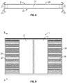
Fig. 9 is a complete front view of the acoustic shutter assembly according to the invention, corresponding to the view ofFig. 2 ; -
Fig. 10 illustrates in part, and on a larger scale, a cross-section along the line X-X ofFig. 9 ; -
Fig. 11 is a perspective view of a top module of the acoustic shutter assembly according to the invention; -
Fig. 12 is the detail XII ofFig. 11 illustrated on a larger scale; and -
Fig. 13 is the detail XIII ofFig. 11 illustrated on a larger scale. -
Fig. 1 shows an embodiment of anacoustic shutter assembly 1 according to the present invention adapted to cover a window opening in a not shown wall. Theacoustic shutter assembly 1 includes awindow pane 2, 3 arranged in aframe 4 having aninside 5 adapted to be mounted on the not shown wall and an outside 6 adapted to face away from said wall. Theframe 4 has four frame members in the form of atop member 23, abottom member 24, afirst side member 25 and asecond side member 26. - A
first ventilation duct 7 is arranged at thefirst side member 25 and asecond ventilation duct 7 is arranged at thesecond side member 26. Eachventilation duct 7 is arranged in theframe 4 between an outer ventilation opening 8 and an inner ventilation opening 9, and theventilation duct 7 extends between afirst layer 10 of sound absorbing material arranged at theinside 5 of theframe 4 and asecond layer 11 of sound absorbing material arranged at theoutside 6 of the frame. The first andsecond layers window pane 2,3. - A number of
acoustic reflectors 12 in the form of metal plate material are arranged between the first andsecond layers ventilation duct 7 is separated into a number ofrespective ventilation channels 13 formed between theacoustic reflectors 12. The metal plate material of eachacoustic reflector 12 is V-formed with afirst leg 16 extending obliquely towards the outer ventilation opening 8 and asecond leg 17 extending obliquely towards the inner ventilation opening 9. Thereby, eachventilation channel 13 changes direction between the outer ventilation opening 8 and the inner ventilation opening 9, so that any linear path from theouter ventilation 8 opening to theinner ventilation opening 9 is blocked. This may of course be achieved with many other forms of theacoustic reflectors 12 than the illustrated V-form. For instance, theacoustic reflectors 12 could form an arc. In the illustrated embodiment, the first andsecond legs acoustic reflector 12 connect midway between the outer ventilation opening 8 and the inner ventilation opening 9 in atop point 18 of theacoustic reflector 12. As illustrated inFig. 10 , eachouter ventilation opening 8 is covered by afilter 19 in the form of a perforated plate. Eachventilation duct 7 is lined by means of a firstperforated plate 14 covering thefirst layer 10 of sound absorbing material and a secondperforated plate 15 covering thesecond layer 11 of sound absorbing material so that theacoustic reflectors 12 extend from the firstperforated plate 14 to the secondperforated plate 15. Theacoustic reflectors 12 are welded to the first and secondperforated plates - The first and
second layers
As illustrated inFig. 10 , between the firstperforated plate 14 and thefirst layer 10 of sound absorbing material and between the secondperforated plate 15 and thesecond layer 11 of sound absorbing material, asound absorbing foil 29 is arranged that may also act as a vapour barrier. - According to the present invention, the
first layer 10 of sound absorbing material has a first thickness t and thesecond layer 11 of sound absorbing material has a second thickness T, and the second thickness T is greater than the first thickness t. In the illustrated embodiment, the first thickness t is 20 millimetres and the second thickness T is 40 millimetres. In any way, according to the present invention, it may be preferred that the second thickness T is preferably at least 4/3 of, more preferred at least 3/2 of, and most preferred about the double of, the first thickness t. - As illustrated in
Figs. 4 to 8 , the at least oneventilation duct 7 is formed in anabsorption module 20 including afirst absorption cassette 21 holding thefirst layer 10 of sound absorbing material and asecond absorption cassette 22 holding thesecond layer 11 of sound absorbing material. It should be noted, however, thatFigs. 4 to 8 illustrate theabsorption module 20 without the first andsecond layers Fig. 8 , eachabsorption cassette U-formed profiles 23 adapted to hold opposed edges of thecorresponding layer perforated plates perforated plates U-formed profile 31. The arrangement of thelayers absorption cassettes Fig. 3 . - As seen for instance in
Fig. 9 , afirst shutter 27 is arranged in its open position at thefirst side member 25 and asecond shutter 28 is arranged in its open position at thesecond side member 26. The first andsecond shutters window pane 2, 3 is covered. - As also seen in
Fig. 9 , thewindow pane 2, 3 is separated in afirst pane part 2 which is slideable to its open position at thefirst side member 25 and a second pane part 3 which is slideable to its open position at thesecond side member 26. In the illustrated situation, the first andsecond pane parts 2, 3 are in their closed positions in which the first andsecond pane parts 2, 3 meet each other and covers the window opening. As seen inFig. 10 , thepane parts 2, 3 are arranged displaceably in a plane extending between thesecond layer 11 of sound absorbing material and a plane in which the first andsecond shutters second layer 11 of sound absorbing material is covered by means of ametal plate 30 in order to cover the outside of the sound absorbing material when the first andsecond shutters - As illustrated in
Figs. 10 and11 , the first andsecond shutters bracket 32 mounted at the upper edge of eachshutter first rollers 33 rolling in atrack 34 of theframe 4 andsecond rollers 35 running on either side of atrack 36 of theframe 4.Pins 46 at the lower edge of eachshutter groove 47 of theframe 4. The first andsecond shutters electric motor 37 by means of awire 38 driven by theelectric motor 37. Thewire 38 runs over afirst wire roller 39 driven by the motor and a secondopposed wire roller 40. Thewire 38 is tensioned by means of atensioning roller 41 held by aspring 42. Thewire 38 is connected to eachshutter respective brackets 43. - The first and
second pane parts 2, 3 are arranged manually displaceably in that rollers 44 at the top of eachpane part 2, 3 roll in atrack 45 of theframe 4. A lower edge 48 of the first andsecond pane parts 2, 3 steers in agroove 49 of theframe 4. -
- t
- thickness of first layer of sound absorbing material
- T
- thickness of second layer of sound absorbing material
- 1
- acoustic shutter assembly
- 2
- left window pane part
- 3
- right window pane part
- 4
- frame
- 5
- inside of frame
- 6
- outside of frame
- 7
- ventilation duct
- 8
- outer ventilation opening
- 9
- inner ventilation opening
- 10
- first layer of sound absorbing material
- 11
- second layer of sound absorbing material
- 12
- acoustic reflector
- 13
- ventilation channel
- 14
- first perforated plate
- 15
- second perforated plate
- 16
- first leg of V-formed acoustic reflector
- 17
- second leg of V-formed acoustic reflector
- 18
- top point of acoustic reflector
- 19
- filter of outer ventilation opening
- 20
- absorption module
- 21
- first absorption cassette
- 22
- second absorption cassette
- 23
- top member of frame
- 24
- bottom member of frame
- 25
- first side member of frame
- 26
- second side member of frame
- 27
- first shutter
- 28
- second shutter
- 29
- sound absorbing foil
- 30
- metal plate
- 31
- U-formed profile
- 32
- bracket
- 33
- first roller
- 34
- track of frame
- 35
- second rollers
- 36
- track of frame
- 37
- electric motor
- 38
- wire
- 39
- first wire roller
- 40
- second wire roller
- 41
- tensioning roller
- 42
- spring
- 43
- brackets
- 44
- roller of pane part
- 45
- track of frame
- 46
- pin of shutter
- 47
- groove of frame
- 48
- lower edge of pane part
- 49
- groove of frame
Claims (10)
- An acoustic shutter assembly (1) adapted to cover a window opening in a wall, including at least one window pane (2, 3) arranged in a frame (4) having an inside (5) adapted to be mounted on the wall and an outside (6) adapted to face away from the wall, wherein at least one ventilation duct (7) is arranged in the frame (4) between an outer ventilation opening (8) and an inner ventilation opening (9), wherein the ventilation duct (7) extends between a first layer (10) of sound absorbing material arranged at the inside (5) of the frame (4) and a second layer (11) of sound absorbing material arranged at the outside (6) of the frame, and wherein the first and second layers (10, 11) of sound absorbing material extend at least substantially in parallel with the window pane (2, 3), wherein a number of acoustic reflectors (12) in the form of plate material are arranged between the first and second layers (10, 11) of sound absorbing material so that the ventilation duct (7) is separated into a number of respective ventilation channels (13) formed between the acoustic reflectors (12), and in that each ventilation channel (13) changes direction at least once between the outer ventilation opening (8) and the inner ventilation opening (9), thereby at least substantially blocking any linear path from the outer ventilation (8) opening to the inner ventilation opening (9).
- An acoustic shutter assembly according to claim 1, wherein the ventilation duct (7) is lined by means of a first perforated plate (14) covering the first layer (10) of sound absorbing material and a second perforated plate (15) covering the second layer (11) of sound absorbing material so that the acoustic reflectors (12) extend from the first perforated plate (14) to the second perforated plate (15).
- An acoustic shutter assembly according to claim 1 or 2, wherein the first layer (10) of sound absorbing material has a first thickness (t) and the second layer (11) of sound absorbing material has a second thickness (T), wherein the second thickness (T) is greater than the first thickness (t), and wherein the second thickness (T) is preferably at least 4/3 of, more preferred at least 3/2 of, and most preferred about the double of, the first thickness (t).
- An acoustic shutter assembly according to any one of the preceding claims, wherein the plate material of each acoustic reflector (12) is V-formed with a first leg (16) extending obliquely towards the outer ventilation opening (8) and a second leg (17) extending obliquely towards the inner ventilation opening (9), and wherein the first and second leg (16, 17) of each acoustic reflector (12) preferably connect at least approximately midway between the outer ventilation opening (8) and the inner ventilation opening (9) in a top point (18) of the acoustic reflector (12).
- An acoustic shutter assembly according to any one of the preceding claims, wherein each outer ventilation opening (8) is covered by a filter (19) in the form of a perforated plate.
- An acoustic shutter assembly according to any one of the preceding claims, wherein the at least one ventilation duct (7) is formed in an absorption module (20) including a first absorption cassette (21) holding the first layer (10) of sound absorbing material and a second absorption cassette (22) holding the second layer (11) of sound absorbing material, and wherein each absorption cassette (21, 22) has at least two opposed U-formed profiles (23) holding opposed edges of the corresponding layer (10, 11) of sound absorbing material.
- An acoustic shutter assembly according to any one of the preceding claims, wherein the frame (4) has four frame members in the form of a top member (23), a bottom member (24), a first side member (25) and a second side member (26), wherein a first ventilation duct (7) is arranged at the first side member (25) and a second ventilation duct (7) is arranged at the second side member (26).
- An acoustic shutter assembly according to claim 7, wherein a first shutter (27) is arranged in its open position at the first side member (25) and a second shutter (28) is arranged in its open position at the second side member (26), and wherein the first and second shutters (27, 28) are arranged displaceably to respective closed positions thereby covering the at least one window pane (2, 3).
- An acoustic shutter assembly according to claim 7 or 8, wherein the at least one window pane (2, 3) is separated in a first pane part (2) arranged in its open position at the first side member (25) and a second pane part (3) arranged in its open position at the second side member (26), and wherein the first and second pane parts (2, 3) are arranged displaceably to respective closed positions in which the first and second pane parts (2, 3) meet each other and covers the window opening.
- An acoustic shutter assembly according to claim 8 and 9, wherein the pane parts (2, 3) are arranged displaceably in a plane extending between a plane of the first and second layers (10, 11) of sound absorbing material and a plane in which the first and second shutters (27, 28) are arranged displaceably.
Applications Claiming Priority (2)
| Application Number | Priority Date | Filing Date | Title |
|---|---|---|---|
| DKPA201770795 | 2017-10-18 | ||
| PCT/EP2018/077759 WO2019076730A1 (en) | 2017-10-18 | 2018-10-11 | Acoustic shutter assembly |
Publications (2)
| Publication Number | Publication Date |
|---|---|
| EP3698003A1 EP3698003A1 (en) | 2020-08-26 |
| EP3698003B1 true EP3698003B1 (en) | 2021-07-28 |
Family
ID=63998688
Family Applications (1)
| Application Number | Title | Priority Date | Filing Date |
|---|---|---|---|
| EP18793187.8A Active EP3698003B1 (en) | 2017-10-18 | 2018-10-11 | Acoustic shutter assembly |
Country Status (5)
| Country | Link |
|---|---|
| US (1) | US11566466B2 (en) |
| EP (1) | EP3698003B1 (en) |
| CA (1) | CA3079296A1 (en) |
| DK (1) | DK3698003T3 (en) |
| WO (1) | WO2019076730A1 (en) |
Family Cites Families (29)
| Publication number | Priority date | Publication date | Assignee | Title |
|---|---|---|---|---|
| US979267A (en) * | 1910-09-17 | 1910-12-20 | Charles Benton Dix | Window attachment. |
| US1783276A (en) * | 1929-02-21 | 1930-12-02 | Howard R Bliss | Sound-controlling ventilating device |
| US1865677A (en) * | 1929-07-19 | 1932-07-05 | Buffalo Forge Co | Sound deadener |
| US1990520A (en) * | 1931-06-04 | 1935-02-12 | Walter D Binger | Noise excluding apparatus |
| US1929595A (en) * | 1931-10-22 | 1933-10-10 | Truscon Steel Co | Sound intercepting ventilator |
| US2704504A (en) * | 1950-02-02 | 1955-03-22 | Arthur O Wilkening | Sound trap and air transfer device |
| US2676678A (en) * | 1951-01-19 | 1954-04-27 | Level Line Ceilings Inc | Wall and wall element |
| US3378100A (en) * | 1965-10-18 | 1968-04-16 | Air Filter Corp | Sound attenuator |
| US3452477A (en) * | 1967-10-06 | 1969-07-01 | John H Sassano | Exterior sliding window shutters |
| FR2318300A1 (en) | 1975-07-18 | 1977-02-11 | Segic | PREFABRICATED INSULATION ELEMENT TO BE FITTED ON AN EXISTING BUILDING BAY AND ASSEMBLY PROCEDURE |
| US4363351A (en) * | 1980-03-10 | 1982-12-14 | George Eriksen | Thermal insulating shutter assembly |
| US4454691A (en) * | 1981-10-02 | 1984-06-19 | Mitchell Robert A | Apparatus for insulating windows and the like |
| CA2164663C (en) * | 1994-12-20 | 1999-08-10 | David B. Martin | Tackable acoustical-barrier panel |
| DE29608765U1 (en) | 1996-05-15 | 1997-09-18 | Haunschild Erwin Dipl Ing | Front window to reduce noise pollution when the windows are open |
| DE19751959A1 (en) | 1997-11-24 | 1999-06-02 | Christian Hirschfelder | Acoustic insulation for window of building |
| GB9920883D0 (en) * | 1999-09-03 | 1999-11-10 | Titon Hardware | Ventilation assemblies |
| US6589112B2 (en) * | 2000-12-29 | 2003-07-08 | Evan Ruach | Duct silencer |
| CN2816299Y (en) | 2003-09-24 | 2006-09-13 | 上海创静环保技术工程有限公司 | Combined bottom-silencing ventilating sound-insulation window |
| US7562743B2 (en) * | 2004-12-02 | 2009-07-21 | Quietly Making Noise, Llc | Acoustical window and door covering |
| CN101215950A (en) | 2007-01-05 | 2008-07-09 | 钟超英 | Environment-friendly energy-saving ventilating sound deadening window |
| JP4935443B2 (en) * | 2007-03-19 | 2012-05-23 | 株式会社日立製作所 | Sound absorption structure of electronic equipment |
| GB0915517D0 (en) * | 2009-09-04 | 2009-10-07 | Ove Arup & Partners Internat L | Sound attenuation air vent |
| WO2012164349A1 (en) | 2011-05-31 | 2012-12-06 | Fraunhofer-Gesellschaft zur Förderung der angewandten Forschung e.V. | Facade element |
| US20150176327A1 (en) * | 2013-12-19 | 2015-06-25 | Green Winows Corp. | Green Windows System |
| US9493949B2 (en) * | 2014-03-20 | 2016-11-15 | Vanair Design | Panel and panel structure for ventilation and both reactive and dissipative sound dampening |
| CN104675287A (en) | 2014-12-15 | 2015-06-03 | 安徽三星环保装备制造有限公司 | Daylighting, ventilation and noise reduction window |
| FR3035432A1 (en) * | 2015-04-21 | 2016-10-28 | Sapa Building Systems France | WINDOW COMPRISING AN ACOUSTIC DAMPING DEVICE |
| US10244662B2 (en) * | 2015-12-11 | 2019-03-26 | International Business Machines Corporation | Method and apparatus for acoustical noise reduction and distributed airflow |
| CN106677685B (en) | 2017-01-19 | 2018-05-29 | 吴光明 | A kind of ventilation and lighting noise reduction window |
-
2018
- 2018-10-11 WO PCT/EP2018/077759 patent/WO2019076730A1/en unknown
- 2018-10-11 CA CA3079296A patent/CA3079296A1/en active Pending
- 2018-10-11 DK DK18793187.8T patent/DK3698003T3/en active
- 2018-10-11 EP EP18793187.8A patent/EP3698003B1/en active Active
- 2018-10-11 US US16/757,164 patent/US11566466B2/en active Active
Also Published As
| Publication number | Publication date |
|---|---|
| US11566466B2 (en) | 2023-01-31 |
| US20200240203A1 (en) | 2020-07-30 |
| CA3079296A1 (en) | 2019-04-25 |
| DK3698003T3 (en) | 2021-11-01 |
| WO2019076730A1 (en) | 2019-04-25 |
| EP3698003A1 (en) | 2020-08-26 |
Similar Documents
| Publication | Publication Date | Title |
|---|---|---|
| JP5452927B2 (en) | High-speed door with flexible curtain | |
| JP5977639B2 (en) | Switchgear | |
| EP3698003B1 (en) | Acoustic shutter assembly | |
| JP5231596B2 (en) | Rainproof panels for houses | |
| JP4691172B2 (en) | Ventilation hood | |
| KR101981600B1 (en) | A structure of window with screen to prevent rainwater | |
| JP4266314B2 (en) | Uchido | |
| JP6978194B2 (en) | Large door device | |
| KR101318730B1 (en) | Complex casement window | |
| JP6140454B2 (en) | Waterproof device for opening | |
| US4425739A (en) | Sliding panel with sound-trap framing | |
| US20080141600A1 (en) | Molding system for accordion hurricane shutters | |
| JP5197450B2 (en) | Building with a gallery door | |
| NL2016894B1 (en) | Window or door covering assembly | |
| JP5995559B2 (en) | Opening device | |
| JP2005061054A (en) | Structure of opening/closing body | |
| JP6426421B2 (en) | shutter | |
| JP2004084418A (en) | Opening/closing device | |
| JP6662718B2 (en) | Curtain wall unit, curtain wall unit assembly, and wall structure | |
| JP2024019816A (en) | curtain wall unit | |
| JP3187505U (en) | Blind shutter | |
| JP2021025275A (en) | Rain prevention cover and water cut-off device | |
| JP2014136898A (en) | Sheet of waterproof device | |
| JPS6013995Y2 (en) | Double sliding door, airtight, adjustable ventilation door. | |
| JP2731868B2 (en) | Soundproof structure of passage using soundproof shutter |
Legal Events
| Date | Code | Title | Description |
|---|---|---|---|
| STAA | Information on the status of an ep patent application or granted ep patent |
Free format text: STATUS: UNKNOWN |
|
| STAA | Information on the status of an ep patent application or granted ep patent |
Free format text: STATUS: THE INTERNATIONAL PUBLICATION HAS BEEN MADE |
|
| PUAI | Public reference made under article 153(3) epc to a published international application that has entered the european phase |
Free format text: ORIGINAL CODE: 0009012 |
|
| STAA | Information on the status of an ep patent application or granted ep patent |
Free format text: STATUS: REQUEST FOR EXAMINATION WAS MADE |
|
| 17P | Request for examination filed |
Effective date: 20200513 |
|
| AK | Designated contracting states |
Kind code of ref document: A1 Designated state(s): AL AT BE BG CH CY CZ DE DK EE ES FI FR GB GR HR HU IE IS IT LI LT LU LV MC MK MT NL NO PL PT RO RS SE SI SK SM TR |
|
| AX | Request for extension of the european patent |
Extension state: BA ME |
|
| DAV | Request for validation of the european patent (deleted) | ||
| DAX | Request for extension of the european patent (deleted) | ||
| GRAP | Despatch of communication of intention to grant a patent |
Free format text: ORIGINAL CODE: EPIDOSNIGR1 |
|
| STAA | Information on the status of an ep patent application or granted ep patent |
Free format text: STATUS: GRANT OF PATENT IS INTENDED |
|
| INTG | Intention to grant announced |
Effective date: 20210211 |
|
| GRAS | Grant fee paid |
Free format text: ORIGINAL CODE: EPIDOSNIGR3 |
|
| GRAA | (expected) grant |
Free format text: ORIGINAL CODE: 0009210 |
|
| STAA | Information on the status of an ep patent application or granted ep patent |
Free format text: STATUS: THE PATENT HAS BEEN GRANTED |
|
| AK | Designated contracting states |
Kind code of ref document: B1 Designated state(s): AL AT BE BG CH CY CZ DE DK EE ES FI FR GB GR HR HU IE IS IT LI LT LU LV MC MK MT NL NO PL PT RO RS SE SI SK SM TR |
|
| REG | Reference to a national code |
Ref country code: GB Ref legal event code: FG4D |
|
| REG | Reference to a national code |
Ref country code: CH Ref legal event code: EP |
|
| REG | Reference to a national code |
Ref country code: DE Ref legal event code: R096 Ref document number: 602018020937 Country of ref document: DE |
|
| REG | Reference to a national code |
Ref country code: AT Ref legal event code: REF Ref document number: 1414885 Country of ref document: AT Kind code of ref document: T Effective date: 20210815 |
|
| REG | Reference to a national code |
Ref country code: IE Ref legal event code: FG4D |
|
| REG | Reference to a national code |
Ref country code: DK Ref legal event code: T3 Effective date: 20211026 |
|
| REG | Reference to a national code |
Ref country code: LT Ref legal event code: MG9D |
|
| REG | Reference to a national code |
Ref country code: NL Ref legal event code: MP Effective date: 20210728 |
|
| REG | Reference to a national code |
Ref country code: AT Ref legal event code: MK05 Ref document number: 1414885 Country of ref document: AT Kind code of ref document: T Effective date: 20210728 |
|
| PG25 | Lapsed in a contracting state [announced via postgrant information from national office to epo] |
Ref country code: RS Free format text: LAPSE BECAUSE OF FAILURE TO SUBMIT A TRANSLATION OF THE DESCRIPTION OR TO PAY THE FEE WITHIN THE PRESCRIBED TIME-LIMIT Effective date: 20210728 Ref country code: SE Free format text: LAPSE BECAUSE OF FAILURE TO SUBMIT A TRANSLATION OF THE DESCRIPTION OR TO PAY THE FEE WITHIN THE PRESCRIBED TIME-LIMIT Effective date: 20210728 Ref country code: FI Free format text: LAPSE BECAUSE OF FAILURE TO SUBMIT A TRANSLATION OF THE DESCRIPTION OR TO PAY THE FEE WITHIN THE PRESCRIBED TIME-LIMIT Effective date: 20210728 Ref country code: ES Free format text: LAPSE BECAUSE OF FAILURE TO SUBMIT A TRANSLATION OF THE DESCRIPTION OR TO PAY THE FEE WITHIN THE PRESCRIBED TIME-LIMIT Effective date: 20210728 Ref country code: HR Free format text: LAPSE BECAUSE OF FAILURE TO SUBMIT A TRANSLATION OF THE DESCRIPTION OR TO PAY THE FEE WITHIN THE PRESCRIBED TIME-LIMIT Effective date: 20210728 Ref country code: NL Free format text: LAPSE BECAUSE OF FAILURE TO SUBMIT A TRANSLATION OF THE DESCRIPTION OR TO PAY THE FEE WITHIN THE PRESCRIBED TIME-LIMIT Effective date: 20210728 Ref country code: PT Free format text: LAPSE BECAUSE OF FAILURE TO SUBMIT A TRANSLATION OF THE DESCRIPTION OR TO PAY THE FEE WITHIN THE PRESCRIBED TIME-LIMIT Effective date: 20211129 Ref country code: NO Free format text: LAPSE BECAUSE OF FAILURE TO SUBMIT A TRANSLATION OF THE DESCRIPTION OR TO PAY THE FEE WITHIN THE PRESCRIBED TIME-LIMIT Effective date: 20211028 Ref country code: LT Free format text: LAPSE BECAUSE OF FAILURE TO SUBMIT A TRANSLATION OF THE DESCRIPTION OR TO PAY THE FEE WITHIN THE PRESCRIBED TIME-LIMIT Effective date: 20210728 Ref country code: BG Free format text: LAPSE BECAUSE OF FAILURE TO SUBMIT A TRANSLATION OF THE DESCRIPTION OR TO PAY THE FEE WITHIN THE PRESCRIBED TIME-LIMIT Effective date: 20211028 Ref country code: AT Free format text: LAPSE BECAUSE OF FAILURE TO SUBMIT A TRANSLATION OF THE DESCRIPTION OR TO PAY THE FEE WITHIN THE PRESCRIBED TIME-LIMIT Effective date: 20210728 |
|
| PG25 | Lapsed in a contracting state [announced via postgrant information from national office to epo] |
Ref country code: PL Free format text: LAPSE BECAUSE OF FAILURE TO SUBMIT A TRANSLATION OF THE DESCRIPTION OR TO PAY THE FEE WITHIN THE PRESCRIBED TIME-LIMIT Effective date: 20210728 Ref country code: LV Free format text: LAPSE BECAUSE OF FAILURE TO SUBMIT A TRANSLATION OF THE DESCRIPTION OR TO PAY THE FEE WITHIN THE PRESCRIBED TIME-LIMIT Effective date: 20210728 Ref country code: GR Free format text: LAPSE BECAUSE OF FAILURE TO SUBMIT A TRANSLATION OF THE DESCRIPTION OR TO PAY THE FEE WITHIN THE PRESCRIBED TIME-LIMIT Effective date: 20211029 |
|
| REG | Reference to a national code |
Ref country code: DE Ref legal event code: R097 Ref document number: 602018020937 Country of ref document: DE |
|
| REG | Reference to a national code |
Ref country code: CH Ref legal event code: PL |
|
| PG25 | Lapsed in a contracting state [announced via postgrant information from national office to epo] |
Ref country code: SM Free format text: LAPSE BECAUSE OF FAILURE TO SUBMIT A TRANSLATION OF THE DESCRIPTION OR TO PAY THE FEE WITHIN THE PRESCRIBED TIME-LIMIT Effective date: 20210728 Ref country code: SK Free format text: LAPSE BECAUSE OF FAILURE TO SUBMIT A TRANSLATION OF THE DESCRIPTION OR TO PAY THE FEE WITHIN THE PRESCRIBED TIME-LIMIT Effective date: 20210728 Ref country code: RO Free format text: LAPSE BECAUSE OF FAILURE TO SUBMIT A TRANSLATION OF THE DESCRIPTION OR TO PAY THE FEE WITHIN THE PRESCRIBED TIME-LIMIT Effective date: 20210728 Ref country code: EE Free format text: LAPSE BECAUSE OF FAILURE TO SUBMIT A TRANSLATION OF THE DESCRIPTION OR TO PAY THE FEE WITHIN THE PRESCRIBED TIME-LIMIT Effective date: 20210728 Ref country code: CZ Free format text: LAPSE BECAUSE OF FAILURE TO SUBMIT A TRANSLATION OF THE DESCRIPTION OR TO PAY THE FEE WITHIN THE PRESCRIBED TIME-LIMIT Effective date: 20210728 Ref country code: AL Free format text: LAPSE BECAUSE OF FAILURE TO SUBMIT A TRANSLATION OF THE DESCRIPTION OR TO PAY THE FEE WITHIN THE PRESCRIBED TIME-LIMIT Effective date: 20210728 |
|
| PLBE | No opposition filed within time limit |
Free format text: ORIGINAL CODE: 0009261 |
|
| STAA | Information on the status of an ep patent application or granted ep patent |
Free format text: STATUS: NO OPPOSITION FILED WITHIN TIME LIMIT |
|
| REG | Reference to a national code |
Ref country code: BE Ref legal event code: MM Effective date: 20211031 |
|
| PG25 | Lapsed in a contracting state [announced via postgrant information from national office to epo] |
Ref country code: MC Free format text: LAPSE BECAUSE OF FAILURE TO SUBMIT A TRANSLATION OF THE DESCRIPTION OR TO PAY THE FEE WITHIN THE PRESCRIBED TIME-LIMIT Effective date: 20210728 |
|
| 26N | No opposition filed |
Effective date: 20220429 |
|
| PG25 | Lapsed in a contracting state [announced via postgrant information from national office to epo] |
Ref country code: LU Free format text: LAPSE BECAUSE OF NON-PAYMENT OF DUE FEES Effective date: 20211011 Ref country code: IT Free format text: LAPSE BECAUSE OF FAILURE TO SUBMIT A TRANSLATION OF THE DESCRIPTION OR TO PAY THE FEE WITHIN THE PRESCRIBED TIME-LIMIT Effective date: 20210728 Ref country code: BE Free format text: LAPSE BECAUSE OF NON-PAYMENT OF DUE FEES Effective date: 20211031 |
|
| PG25 | Lapsed in a contracting state [announced via postgrant information from national office to epo] |
Ref country code: LI Free format text: LAPSE BECAUSE OF NON-PAYMENT OF DUE FEES Effective date: 20211031 Ref country code: CH Free format text: LAPSE BECAUSE OF NON-PAYMENT OF DUE FEES Effective date: 20211031 |
|
| PG25 | Lapsed in a contracting state [announced via postgrant information from national office to epo] |
Ref country code: IE Free format text: LAPSE BECAUSE OF NON-PAYMENT OF DUE FEES Effective date: 20211011 |
|
| PG25 | Lapsed in a contracting state [announced via postgrant information from national office to epo] |
Ref country code: CY Free format text: LAPSE BECAUSE OF FAILURE TO SUBMIT A TRANSLATION OF THE DESCRIPTION OR TO PAY THE FEE WITHIN THE PRESCRIBED TIME-LIMIT Effective date: 20210728 |
|
| PG25 | Lapsed in a contracting state [announced via postgrant information from national office to epo] |
Ref country code: HU Free format text: LAPSE BECAUSE OF FAILURE TO SUBMIT A TRANSLATION OF THE DESCRIPTION OR TO PAY THE FEE WITHIN THE PRESCRIBED TIME-LIMIT; INVALID AB INITIO Effective date: 20181011 |
|
| PGFP | Annual fee paid to national office [announced via postgrant information from national office to epo] |
Ref country code: GB Payment date: 20231020 Year of fee payment: 6 |
|
| PGFP | Annual fee paid to national office [announced via postgrant information from national office to epo] |
Ref country code: FR Payment date: 20231026 Year of fee payment: 6 Ref country code: DK Payment date: 20231024 Year of fee payment: 6 Ref country code: DE Payment date: 20231020 Year of fee payment: 6 |