EP3697612B1 - Verbessertes ausrichtungs- und verbundverfahren für die herstellung von dünnem verbundglas aus glasscheiben mit fehlender passgenauigkeit - Google Patents
Verbessertes ausrichtungs- und verbundverfahren für die herstellung von dünnem verbundglas aus glasscheiben mit fehlender passgenauigkeit Download PDFInfo
- Publication number
- EP3697612B1 EP3697612B1 EP18773199.7A EP18773199A EP3697612B1 EP 3697612 B1 EP3697612 B1 EP 3697612B1 EP 18773199 A EP18773199 A EP 18773199A EP 3697612 B1 EP3697612 B1 EP 3697612B1
- Authority
- EP
- European Patent Office
- Prior art keywords
- arrangement
- glass
- glass pane
- heated
- roller
- Prior art date
- Legal status (The legal status is an assumption and is not a legal conclusion. Google has not performed a legal analysis and makes no representation as to the accuracy of the status listed.)
- Active
Links
Images

Classifications
-
- B—PERFORMING OPERATIONS; TRANSPORTING
- B32—LAYERED PRODUCTS
- B32B—LAYERED PRODUCTS, i.e. PRODUCTS BUILT-UP OF STRATA OF FLAT OR NON-FLAT, e.g. CELLULAR OR HONEYCOMB, FORM
- B32B17/00—Layered products essentially comprising sheet glass, or glass, slag, or like fibres
- B32B17/06—Layered products essentially comprising sheet glass, or glass, slag, or like fibres comprising glass as the main or only constituent of a layer, next to another layer of a specific material
- B32B17/10—Layered products essentially comprising sheet glass, or glass, slag, or like fibres comprising glass as the main or only constituent of a layer, next to another layer of a specific material of synthetic resin
- B32B17/10005—Layered products essentially comprising sheet glass, or glass, slag, or like fibres comprising glass as the main or only constituent of a layer, next to another layer of a specific material of synthetic resin laminated safety glass or glazing
- B32B17/10009—Layered products essentially comprising sheet glass, or glass, slag, or like fibres comprising glass as the main or only constituent of a layer, next to another layer of a specific material of synthetic resin laminated safety glass or glazing characterized by the number, the constitution or treatment of glass sheets
- B32B17/10036—Layered products essentially comprising sheet glass, or glass, slag, or like fibres comprising glass as the main or only constituent of a layer, next to another layer of a specific material of synthetic resin laminated safety glass or glazing characterized by the number, the constitution or treatment of glass sheets comprising two outer glass sheets
-
- B—PERFORMING OPERATIONS; TRANSPORTING
- B32—LAYERED PRODUCTS
- B32B—LAYERED PRODUCTS, i.e. PRODUCTS BUILT-UP OF STRATA OF FLAT OR NON-FLAT, e.g. CELLULAR OR HONEYCOMB, FORM
- B32B17/00—Layered products essentially comprising sheet glass, or glass, slag, or like fibres
- B32B17/06—Layered products essentially comprising sheet glass, or glass, slag, or like fibres comprising glass as the main or only constituent of a layer, next to another layer of a specific material
- B32B17/10—Layered products essentially comprising sheet glass, or glass, slag, or like fibres comprising glass as the main or only constituent of a layer, next to another layer of a specific material of synthetic resin
- B32B17/10005—Layered products essentially comprising sheet glass, or glass, slag, or like fibres comprising glass as the main or only constituent of a layer, next to another layer of a specific material of synthetic resin laminated safety glass or glazing
- B32B17/10807—Making laminated safety glass or glazing; Apparatus therefor
- B32B17/10816—Making laminated safety glass or glazing; Apparatus therefor by pressing
- B32B17/10871—Making laminated safety glass or glazing; Apparatus therefor by pressing in combination with particular heat treatment
-
- B—PERFORMING OPERATIONS; TRANSPORTING
- B32—LAYERED PRODUCTS
- B32B—LAYERED PRODUCTS, i.e. PRODUCTS BUILT-UP OF STRATA OF FLAT OR NON-FLAT, e.g. CELLULAR OR HONEYCOMB, FORM
- B32B1/00—Layered products having a non-planar shape
-
- B—PERFORMING OPERATIONS; TRANSPORTING
- B32—LAYERED PRODUCTS
- B32B—LAYERED PRODUCTS, i.e. PRODUCTS BUILT-UP OF STRATA OF FLAT OR NON-FLAT, e.g. CELLULAR OR HONEYCOMB, FORM
- B32B17/00—Layered products essentially comprising sheet glass, or glass, slag, or like fibres
- B32B17/06—Layered products essentially comprising sheet glass, or glass, slag, or like fibres comprising glass as the main or only constituent of a layer, next to another layer of a specific material
- B32B17/10—Layered products essentially comprising sheet glass, or glass, slag, or like fibres comprising glass as the main or only constituent of a layer, next to another layer of a specific material of synthetic resin
- B32B17/10005—Layered products essentially comprising sheet glass, or glass, slag, or like fibres comprising glass as the main or only constituent of a layer, next to another layer of a specific material of synthetic resin laminated safety glass or glazing
- B32B17/1055—Layered products essentially comprising sheet glass, or glass, slag, or like fibres comprising glass as the main or only constituent of a layer, next to another layer of a specific material of synthetic resin laminated safety glass or glazing characterized by the resin layer, i.e. interlayer
- B32B17/10761—Layered products essentially comprising sheet glass, or glass, slag, or like fibres comprising glass as the main or only constituent of a layer, next to another layer of a specific material of synthetic resin laminated safety glass or glazing characterized by the resin layer, i.e. interlayer containing vinyl acetal
-
- B—PERFORMING OPERATIONS; TRANSPORTING
- B32—LAYERED PRODUCTS
- B32B—LAYERED PRODUCTS, i.e. PRODUCTS BUILT-UP OF STRATA OF FLAT OR NON-FLAT, e.g. CELLULAR OR HONEYCOMB, FORM
- B32B17/00—Layered products essentially comprising sheet glass, or glass, slag, or like fibres
- B32B17/06—Layered products essentially comprising sheet glass, or glass, slag, or like fibres comprising glass as the main or only constituent of a layer, next to another layer of a specific material
- B32B17/10—Layered products essentially comprising sheet glass, or glass, slag, or like fibres comprising glass as the main or only constituent of a layer, next to another layer of a specific material of synthetic resin
- B32B17/10005—Layered products essentially comprising sheet glass, or glass, slag, or like fibres comprising glass as the main or only constituent of a layer, next to another layer of a specific material of synthetic resin laminated safety glass or glazing
- B32B17/10807—Making laminated safety glass or glazing; Apparatus therefor
- B32B17/10816—Making laminated safety glass or glazing; Apparatus therefor by pressing
-
- B—PERFORMING OPERATIONS; TRANSPORTING
- B32—LAYERED PRODUCTS
- B32B—LAYERED PRODUCTS, i.e. PRODUCTS BUILT-UP OF STRATA OF FLAT OR NON-FLAT, e.g. CELLULAR OR HONEYCOMB, FORM
- B32B17/00—Layered products essentially comprising sheet glass, or glass, slag, or like fibres
- B32B17/06—Layered products essentially comprising sheet glass, or glass, slag, or like fibres comprising glass as the main or only constituent of a layer, next to another layer of a specific material
- B32B17/10—Layered products essentially comprising sheet glass, or glass, slag, or like fibres comprising glass as the main or only constituent of a layer, next to another layer of a specific material of synthetic resin
- B32B17/10005—Layered products essentially comprising sheet glass, or glass, slag, or like fibres comprising glass as the main or only constituent of a layer, next to another layer of a specific material of synthetic resin laminated safety glass or glazing
- B32B17/10807—Making laminated safety glass or glazing; Apparatus therefor
- B32B17/10889—Making laminated safety glass or glazing; Apparatus therefor shaping the sheets, e.g. by using a mould
-
- B—PERFORMING OPERATIONS; TRANSPORTING
- B32—LAYERED PRODUCTS
- B32B—LAYERED PRODUCTS, i.e. PRODUCTS BUILT-UP OF STRATA OF FLAT OR NON-FLAT, e.g. CELLULAR OR HONEYCOMB, FORM
- B32B17/00—Layered products essentially comprising sheet glass, or glass, slag, or like fibres
- B32B17/06—Layered products essentially comprising sheet glass, or glass, slag, or like fibres comprising glass as the main or only constituent of a layer, next to another layer of a specific material
- B32B17/10—Layered products essentially comprising sheet glass, or glass, slag, or like fibres comprising glass as the main or only constituent of a layer, next to another layer of a specific material of synthetic resin
- B32B17/10005—Layered products essentially comprising sheet glass, or glass, slag, or like fibres comprising glass as the main or only constituent of a layer, next to another layer of a specific material of synthetic resin laminated safety glass or glazing
- B32B17/10807—Making laminated safety glass or glazing; Apparatus therefor
- B32B17/10899—Making laminated safety glass or glazing; Apparatus therefor by introducing interlayers of synthetic resin
- B32B17/10935—Making laminated safety glass or glazing; Apparatus therefor by introducing interlayers of synthetic resin as a preformed layer, e.g. formed by extrusion
-
- B—PERFORMING OPERATIONS; TRANSPORTING
- B32—LAYERED PRODUCTS
- B32B—LAYERED PRODUCTS, i.e. PRODUCTS BUILT-UP OF STRATA OF FLAT OR NON-FLAT, e.g. CELLULAR OR HONEYCOMB, FORM
- B32B17/00—Layered products essentially comprising sheet glass, or glass, slag, or like fibres
- B32B17/06—Layered products essentially comprising sheet glass, or glass, slag, or like fibres comprising glass as the main or only constituent of a layer, next to another layer of a specific material
- B32B17/10—Layered products essentially comprising sheet glass, or glass, slag, or like fibres comprising glass as the main or only constituent of a layer, next to another layer of a specific material of synthetic resin
- B32B17/10005—Layered products essentially comprising sheet glass, or glass, slag, or like fibres comprising glass as the main or only constituent of a layer, next to another layer of a specific material of synthetic resin laminated safety glass or glazing
- B32B17/10807—Making laminated safety glass or glazing; Apparatus therefor
- B32B17/10972—Degassing during the lamination
-
- B—PERFORMING OPERATIONS; TRANSPORTING
- B32—LAYERED PRODUCTS
- B32B—LAYERED PRODUCTS, i.e. PRODUCTS BUILT-UP OF STRATA OF FLAT OR NON-FLAT, e.g. CELLULAR OR HONEYCOMB, FORM
- B32B27/00—Layered products comprising a layer of synthetic resin
- B32B27/30—Layered products comprising a layer of synthetic resin comprising vinyl (co)polymers; comprising acrylic (co)polymers
-
- B—PERFORMING OPERATIONS; TRANSPORTING
- B32—LAYERED PRODUCTS
- B32B—LAYERED PRODUCTS, i.e. PRODUCTS BUILT-UP OF STRATA OF FLAT OR NON-FLAT, e.g. CELLULAR OR HONEYCOMB, FORM
- B32B37/00—Methods or apparatus for laminating, e.g. by curing or by ultrasonic bonding
- B32B37/0046—Methods or apparatus for laminating, e.g. by curing or by ultrasonic bonding characterised by constructional aspects of the apparatus
- B32B37/0053—Constructional details of laminating machines comprising rollers; Constructional features of the rollers
-
- B—PERFORMING OPERATIONS; TRANSPORTING
- B32—LAYERED PRODUCTS
- B32B—LAYERED PRODUCTS, i.e. PRODUCTS BUILT-UP OF STRATA OF FLAT OR NON-FLAT, e.g. CELLULAR OR HONEYCOMB, FORM
- B32B37/00—Methods or apparatus for laminating, e.g. by curing or by ultrasonic bonding
- B32B37/06—Methods or apparatus for laminating, e.g. by curing or by ultrasonic bonding characterised by the heating method
-
- B—PERFORMING OPERATIONS; TRANSPORTING
- B32—LAYERED PRODUCTS
- B32B—LAYERED PRODUCTS, i.e. PRODUCTS BUILT-UP OF STRATA OF FLAT OR NON-FLAT, e.g. CELLULAR OR HONEYCOMB, FORM
- B32B37/00—Methods or apparatus for laminating, e.g. by curing or by ultrasonic bonding
- B32B37/10—Methods or apparatus for laminating, e.g. by curing or by ultrasonic bonding characterised by the pressing technique, e.g. using action of vacuum or fluid pressure
-
- B—PERFORMING OPERATIONS; TRANSPORTING
- B32—LAYERED PRODUCTS
- B32B—LAYERED PRODUCTS, i.e. PRODUCTS BUILT-UP OF STRATA OF FLAT OR NON-FLAT, e.g. CELLULAR OR HONEYCOMB, FORM
- B32B37/00—Methods or apparatus for laminating, e.g. by curing or by ultrasonic bonding
- B32B37/14—Methods or apparatus for laminating, e.g. by curing or by ultrasonic bonding characterised by the properties of the layers
- B32B37/16—Methods or apparatus for laminating, e.g. by curing or by ultrasonic bonding characterised by the properties of the layers with all layers existing as coherent layers before laminating
- B32B37/18—Methods or apparatus for laminating, e.g. by curing or by ultrasonic bonding characterised by the properties of the layers with all layers existing as coherent layers before laminating involving the assembly of discrete sheets or panels only
- B32B37/182—Methods or apparatus for laminating, e.g. by curing or by ultrasonic bonding characterised by the properties of the layers with all layers existing as coherent layers before laminating involving the assembly of discrete sheets or panels only one or more of the layers being plastic
-
- B—PERFORMING OPERATIONS; TRANSPORTING
- B32—LAYERED PRODUCTS
- B32B—LAYERED PRODUCTS, i.e. PRODUCTS BUILT-UP OF STRATA OF FLAT OR NON-FLAT, e.g. CELLULAR OR HONEYCOMB, FORM
- B32B38/00—Ancillary operations in connection with laminating processes
- B32B38/18—Handling of layers or the laminate
- B32B38/1825—Handling of layers or the laminate characterised by the control or constructional features of devices for tensioning, stretching or registration
- B32B38/1833—Positioning, e.g. registration or centering
- B32B38/1841—Positioning, e.g. registration or centering during laying up
-
- B—PERFORMING OPERATIONS; TRANSPORTING
- B60—VEHICLES IN GENERAL
- B60J—WINDOWS, WINDSCREENS, NON-FIXED ROOFS, DOORS, OR SIMILAR DEVICES FOR VEHICLES; REMOVABLE EXTERNAL PROTECTIVE COVERINGS SPECIALLY ADAPTED FOR VEHICLES
- B60J1/00—Windows; Windscreens; Accessories therefor
- B60J1/08—Windows; Windscreens; Accessories therefor arranged at vehicle sides
-
- B—PERFORMING OPERATIONS; TRANSPORTING
- B32—LAYERED PRODUCTS
- B32B—LAYERED PRODUCTS, i.e. PRODUCTS BUILT-UP OF STRATA OF FLAT OR NON-FLAT, e.g. CELLULAR OR HONEYCOMB, FORM
- B32B2250/00—Layers arrangement
- B32B2250/03—3 layers
-
- B—PERFORMING OPERATIONS; TRANSPORTING
- B32—LAYERED PRODUCTS
- B32B—LAYERED PRODUCTS, i.e. PRODUCTS BUILT-UP OF STRATA OF FLAT OR NON-FLAT, e.g. CELLULAR OR HONEYCOMB, FORM
- B32B2250/00—Layers arrangement
- B32B2250/40—Symmetrical or sandwich layers, e.g. ABA, ABCBA, ABCCBA
-
- B—PERFORMING OPERATIONS; TRANSPORTING
- B32—LAYERED PRODUCTS
- B32B—LAYERED PRODUCTS, i.e. PRODUCTS BUILT-UP OF STRATA OF FLAT OR NON-FLAT, e.g. CELLULAR OR HONEYCOMB, FORM
- B32B2309/00—Parameters for the laminating or treatment process; Apparatus details
- B32B2309/02—Temperature
-
- B—PERFORMING OPERATIONS; TRANSPORTING
- B32—LAYERED PRODUCTS
- B32B—LAYERED PRODUCTS, i.e. PRODUCTS BUILT-UP OF STRATA OF FLAT OR NON-FLAT, e.g. CELLULAR OR HONEYCOMB, FORM
- B32B2315/00—Other materials containing non-metallic inorganic compounds not provided for in groups B32B2311/00 - B32B2313/04
- B32B2315/08—Glass
-
- B—PERFORMING OPERATIONS; TRANSPORTING
- B32—LAYERED PRODUCTS
- B32B—LAYERED PRODUCTS, i.e. PRODUCTS BUILT-UP OF STRATA OF FLAT OR NON-FLAT, e.g. CELLULAR OR HONEYCOMB, FORM
- B32B2329/00—Polyvinylalcohols, polyvinylethers, polyvinylaldehydes, polyvinylketones or polyvinylketals
- B32B2329/06—PVB, i.e. polyinylbutyral
-
- B—PERFORMING OPERATIONS; TRANSPORTING
- B32—LAYERED PRODUCTS
- B32B—LAYERED PRODUCTS, i.e. PRODUCTS BUILT-UP OF STRATA OF FLAT OR NON-FLAT, e.g. CELLULAR OR HONEYCOMB, FORM
- B32B2605/00—Vehicles
- B32B2605/006—Transparent parts other than made from inorganic glass, e.g. polycarbonate glazings
-
- B—PERFORMING OPERATIONS; TRANSPORTING
- B32—LAYERED PRODUCTS
- B32B—LAYERED PRODUCTS, i.e. PRODUCTS BUILT-UP OF STRATA OF FLAT OR NON-FLAT, e.g. CELLULAR OR HONEYCOMB, FORM
- B32B2605/00—Vehicles
- B32B2605/08—Cars
Definitions
- the invention relates to a method for producing a laminated glass or a precursor thereof.
- a laminated glass or a laminated glass pane consists of at least a first pane or outer pane, a second pane or inner pane and a polymeric intermediate layer which connects the first pane to the second pane.
- Laminated glass is used, for example, as vehicle panes or window panes for buildings.
- Laminated glass can be flat or curved laminated glass.
- Thin laminated glass is understood here to mean laminated glass in which one of the two glass panes has a thickness of no more than 1.0 mm.
- the other pane of the laminated glass may be of standard glass thicknesses, typically at least 1.4mm thick, for example 1.6mm thick.
- Known processes for producing laminated glass typically involve assembling a first pane, one or more laminating films and a second pane, deaerating the resulting assembly to form a pre-laminate, and heat and/or pressure treating the resulting pre-laminate to obtain the finished laminated glass pane . Furthermore, if curved laminated glass is to be produced, it is necessary to bend the glass sheets prior to forming the assembly.
- the glass panes used substantially match each other in curvature and shape so that they can be folded and aligned relatively accurately into the assembly.
- the geometry of the two glass panes for the production of the laminated glass does not fit, ie differ in terms of curvature and/or in local areas in terms of shape. This can be due, for example, to Deficiencies in the manufacturing process of the glass panes used arise or be due to process technology.
- a lack of accuracy of fit in the geometry of the two panes of glass results in the arrangement resulting when the panes are put together having gaps or gaps, making it difficult to align the arrangement and causing problems in the subsequent production steps for producing the laminated glass. It goes without saying that these problems become greater the more pronounced the lack of fitting accuracy in the geometry is. The consequences can be, for example, errors or inaccuracies in the alignment of the panes in the laminated glass obtained. If the lack of fitting accuracy is too pronounced, it is no longer possible with the known methods according to the prior art to align the panes with one another with the required precision.
- EP 3189965 A1 relates to a laminated panel comprising first and second discs, the first disc being thicker than the second disc, the first disc having a linear chamfered portion in the outer periphery, and the second disc offset on an extended line of the linear chamfered portion of the first disk is positioned.
- the curvature of the first and second discs can be different.
- FR3012073A1 relates to a curved laminated glass unit having an outer glass sheet and an inner glass sheet, the inner glass sheet being thinner than the outer glass sheet, and a method of making the laminated glass which may involve cold bending of the inner glass sheet.
- GB 908338A describes a method of manufacturing planar or curved laminated glass in which an assembly of two thin sheets of glass and interlayers is fixed between two cover plates by means of clamps or other gripping means around the entire perimeter of the assembly and then the assembly thus fixed is laminated in an autoclave becomes.
- U.S. 2007/223096 A1 describes a reflector in which components of a glass laminate are fixed with clips.
- DE 102006054736 A1 relates to a process for the production of laminated glass, in which two glass plates, each with a film layer, are placed on top of one another to form a glass package and the glass package is transported to a laminating device, where it is laminated under vacuum and the film layer is melted to form laminated glass, with the glass package being laid on top of one another and before the Transport is at least partially heated to fix the glass plates relative to the film.
- pressure can be applied using pressure rollers.
- DE 3728284 A1 describes the alignment of two glass panes to be connected using an alignment table and adjustment stops.
- DE 4106958 A1 relates to a method for producing curved, interconnected panes of glass with a spacer element inserted between the panes, each pane being brought into contact with a contact surface and being firmly connected to it after precise alignment relative to this contact surface.
- the method should be suitable for the assembly of a thin laminated glass with two glass panes with a lack of fitting accuracy in terms of geometry.
- the inventive method allows the alignment and fixation of the assembly of glass panes with a lack of accuracy of fit to form a fixed assembly for manufacturing a thin laminated glass with high precision and repeatability for automated, semi-automated or manual manufacturing.
- the method according to the invention is particularly suitable when using two panes of glass that do not have a precise fit in terms of geometry.
- the difficulties described above, which are caused by such a lack of fitting accuracy in the known methods, can be overcome by the method according to the invention. Even pairs of glass panes with a pronounced lack of fitting accuracy can be processed in the method according to the invention.
- the preliminary stage of a laminated glass is understood here in particular to mean the fixed arrangement obtained after step c) or the deaerated preliminary composite which is obtained after the optional deaeration of the fixed arrangement obtained after step c).
- curvature or bending and curved or bent are synonymous terms here.
- a roller arrangement is to be understood as meaning an arrangement comprising at least one pair of rollers made up of two opposite rollers.
- the laminated glass can be flat or curved, with a curved laminated glass being preferred.
- the laminated glass can be curved in one or more directions of space, as is usual for example for motor vehicle windows.
- Typical radii of curvature can be, for example, in the range from about 20 mm to about 40 m, preferably 50 mm to 30 m.
- a first glass pane with a thickness of at least 1.4 mm and a second glass pane with a thickness of not more than 1.0 mm are used.
- the method thus relates to the production of a thin laminated glass.
- the first glass pane can be flat or curved.
- the second pane of glass can be flat or curved.
- glass sheets can be curved by a gravity bending process.
- the first glass pane used and the second glass pane used differ in terms of their curvature and/or their shape in local areas. As already mentioned, this represents a lack of accuracy of fit in the geometry of the two panes of glass that are to be laminated to form the laminated glass. These differences in curvature and/or localized areas in shape usually result in the formation of gaps or crevices in the assembly when the two sheets of glass are superimposed into the assembly with the at least one laminating film therebetween.
- the first glass pane can have a stronger curvature than the second glass pane and vice versa.
- a different curvature of the first and second glass sheets also includes cases where one of the two glass sheets is flat and the other is curved. The difference in curvature of the two panes of glass can be significant.
- Differences in the shape of the first glass pane and the second glass pane used in local areas represent local shape deviations or shape defects. These can be, for example, bulges, waves or depressions as well as inconsistencies in the thickness that are present in the glass pane or panes. These can, for example, be due to process technology or result from errors in the manufacturing process. Such errors in local areas in the shape can lead to a lack of accuracy of fit in the geometry even when using two flat panes of glass.
- the curvature of the first and second glass panes differs, with differences in shape also possibly existing in local areas.
- the first glass pane used is curved and the second glass pane used is not curved or flat or has a smaller curvature than the first glass pane.
- the difference in the curvature of the two panes of glass can be considerable.
- the thinner second sheet of glass has no curvature and the thicker first sheet of glass has a curvature designed to match the final product (laminated glass) as closely as possible to the desired CAD (computer-aided design) shape. matches.
- the first glass sheet preferably has a thickness in the range 1.4mm to 5.0mm, more preferably 1.6mm to 2.2mm.
- the second glass sheet preferably has a thickness in the range 0.3 to 1.0 mm, more preferably 0.5 to 0.8 mm.
- the first pane of glass and the second pane of glass may be of the same material or of different materials.
- the glass panes can be formed from inorganic glass and/or organic glass, ie organic polymers.
- the first glass pane and/or the second glass pane are formed from flat glass, quartz glass, borosilicate glass, soda-lime glass, alkali aluminosilicate glass, polycarbonate and/or polymethacrylate.
- the first and/or second glass pane can be formed from non-tempered glass, thermally or chemically partially tempered glass (TVG) or thermally (ESG) or chemically tempered glass.
- At least one laminating film which is located in the arrangement between the first and second panes of glass, is used to create the arrangement.
- the at least one laminating film is in particular a polymer film, preferably a thermoplastic polymer film.
- One or more laminating films are usually used.
- the at least one laminating film serves to bond the first glass pane and the second glass pane together to form the laminate or laminated glass.
- laminating pouches e.g. 1, 2 or 3 laminating pouches
- laminating films are well known to those skilled in the art and are commercially available.
- the laminating film for example a PVB film, has for example a thickness of from 0.1 to 2 mm and more preferably from 0.3 to 1 mm, typically 0.38 mm or 0.76 mm or 0.81 mm or 0.84 mm.
- the laminating film may be formed from, for example, polyvinyl butyral (PVB), ethylene vinyl acetate (EVA), polyurethane, a copolymer thereof, a derivative thereof, or mixtures thereof, with PVB films being particularly preferred.
- PVB films are particularly preferred.
- the laminating film can optionally contain customary additives, such as plasticizers or fillers.
- one or more additional polymer films different from the laminating film can be used for the arrangement, which are also arranged between the first and second panes of glass, e.g. an infrared-reflecting polymer film, e.g. a polyester film, which may have a coating, e.g. silver.
- the assembly comprising the first sheet of glass, the second sheet of glass and at least one between the first and second sheets of glass located laminating film, the first glass pane, the at least one laminating film and the second glass pane are superimposed.
- one or more additional polymer films can optionally be arranged between the two panes of glass.
- the method according to the invention comprises as step a) aligning the arrangement, comprising the first glass pane, the second glass pane and the at least one laminating film located between the first and second glass panes, by positioning at least one side edge of the arrangement on at least one stop element.
- stop elements can be used, expediently at least three. All standard stop elements can be used, e.g. vertically positioned cylinders which are fixed to the floor or a standard stop device in the desired arrangement.
- At least one side edge of the arrangement is positioned against at least one stop element by pressing the side edge against the stop element so that the side edge lies against the stop element.
- any side edge can be selected for positioning on the stop element, but the side edge with the greatest importance is expediently selected, since the greatest accuracy in alignment is achieved at the positioned side edge.
- the side edge with the greatest importance is the top side edge, since this can be visible when installed.
- At least two, usually at least three, stop elements are arranged in such a way that the side edge to be pre-fixed can be positioned on at least one, preferably at least two stop elements, and a side edge touching the side edge to be pre-fixed can be positioned on at least one stop element to achieve accurate alignment.
- At least three stop elements are used to align the arrangement, which are arranged in such a way that the side edge of the arrangement to be prefixed is positioned on at least two stop elements and another side edge of the arrangement that touches the side edge to be prefixed is positioned on at least one stop element.
- Such an embodiment is in 2 illustrated.
- step b) the aligned assembly is pre-fixed at two or more locations on the positioned side edge of the assembly by one or more, usually at least two, fixing elements and heating.
- the fixing element can optionally be heatable. All means for mechanical fixing familiar to the person skilled in the art can be used as the fixing element.
- the fixing element can be a clamp, for example.
- the clip can be heatable. A force perpendicular to the glass surface can be applied by the fixing element.
- the fixing element or elements are attached to the at least two points on the positioned side edge and the points are heated selectively or locally by applying a force normal to the glass surface, as a result of which the pre-fixing of the arrangement is achieved.
- the punctiform heating at the points mentioned can take place e.g. by means of hot air and/or one or more heated fixing elements, in particular heated clamps. Hot air blowers, for example, can be used to generate the hot air.
- the punctiform heating of the at least two points makes the laminating film adhesive at these points, so that the pre-fixing is achieved by the local bonding.
- the appropriate temperature naturally depends on the type of laminating film used.
- the arrangement is heated at the points to be fixed, for example to a temperature in the range from 30.degree. C. to 140.degree. C., preferably from 40.degree. C. to 100.degree. Since the time for heating should be kept as short as possible, the temperature of the hot air and/or the heated fixing elements is usually significantly higher in order to reach the desired temperature in the arrangement as quickly as possible.
- the fixing element or elements are removed from the arrangement again, as a result of which the pre-fixed arrangement is obtained.
- a fixed arrangement is then formed in step c) by passing the pre-fixed arrangement through a roller arrangement with the pre-fixed side edge of the arrangement in front, the arrangement being heated at least in sections during the passage.
- the roller arrangement used preferably has a plurality of pairs of rollers arranged next to one another and consisting of two rollers located opposite one another, with at least one pair of rollers possibly being heatable.
- the roller arrangement is particularly preferably a calender roller arrangement. This preferably has a plurality of pairs of rollers arranged next to one another and consisting of two rollers located opposite one another, with at least one pair of rollers being heatable if necessary.
- the arrangement is heated at least in sections during the passage.
- the two glass panes are connected by the laminating film which is adhesive there, as a result of which the fixed arrangement is obtained.
- the arrangement is heated only in sections during the passage, ie not over the entire surface but over part of the surface or in strips. In this way, the arrangement is not connected over the entire surface but only in sections, which makes it easier to vent, if necessary, subsequently.
- the arrangement which is prefixed at least in sections, is preferably heated in step c) by hot air and/or one or more heated pairs of rollers of the roller arrangement, in particular a calender roller arrangement.
- Hot air blowers for example, can be used to generate the hot air.
- the appropriate temperature naturally depends on the type of laminating film used.
- the arrangement is heated at least in sections, preferably only in sections, for example to a temperature in the range from 30.degree. C. to 140.degree. C., preferably from 40.degree. C. to 100.degree.
- the prefixed arrangement is heated in sections or strips by using a roller arrangement, in particular a calender roller arrangement, with several pairs of rollers arranged next to one another, with some of the pairs of rollers not being heated and at least one pair of rollers being heated. If two or more pairs of rollers are heated, there is preferably at least one unheated pair of rollers between each pair of heated rollers.
- the contact pressure exerted on the pre-fixed arrangement in the roller arrangement, in particular the calender roller arrangement, relative to the atmospheric pressure can be, for example, 2 to 5 bar, preferably 3 to 4 bar.
- the fixed arrangement is formed by passing the pre-fixed arrangement through the roller arrangement, which can in particular be designed as a calender roller arrangement, with heating at least in sections, preferably in sections.
- a further effect can result from the passage of the pre-fixed arrangement through the roller arrangement, which can in particular be designed as a calender roller arrangement.
- This consists in the fact that the lack of a precise fit in the geometry of the two panes of glass can be compensated for.
- previously existing differences in the curvature of the two panes of glass can be compensated.
- existing differences in the curvature of the first and second glass panes are compensated for by the treatment in step c) by completely or partially adapting the curvature of the thinner second glass pane to the curvature of the thicker first glass pane.
- the method according to the invention can also optionally and preferably include a deaeration step, in which the fixed arrangement obtained in step c) is subjected to a deaeration process to form a pre-composite.
- the deaeration can take place according to the known methods, for example by a calender treatment or by a vacuum method, a vacuum method being preferred.
- a vacuum is applied to the fixed assembly, which has been placed, for example, in a vacuum bag or vacuum frame, and residual air is evacuated from the fixed assembly.
- the venting process preferably by the vacuum method, usually also involves heating the fixed arrangement.
- the process according to the invention can also optionally and preferably comprise a heat and/or pressure treatment of the prelaminate obtained after deaeration in order to finish the laminated glass.
- This heat and/or pressure treatment of the pre-laminate obtained after deaeration to form the laminated glass can be carried out by any of the methods well known to those skilled in the art, with the autoclave method being preferred.
- the laminated glass is preferably a vehicle pane, particularly preferably a motor vehicle pane.
- the vehicle can be a land, ship or aircraft, in particular a passenger car.
- the laminated glass is preferably a side window for a vehicle, preferably for a motor vehicle.
- FIG. 1 shows schematically a side view of the assembly 13, comprising a first glass pane 11, a second glass pane 12 and a laminating film 14, e.g from PVB, during steps a) and b) of the process for the manufacture of a vehicle window pane.
- the first glass pane 11 has a thickness of 1.6 mm and a clear curvature.
- the laminating film 14 is located between the first glass pane 11 and the second glass pane 12.
- the second glass pane 12 has a thickness of no more than 1.0 mm, for example 0.6 mm, and is flat and not curved. Due to the different curvature, the glass panes 11, 12 have a lack of accuracy of fit in terms of geometry. This creates a gap in the arrangement 13.
- the upper figure from 1 shows the alignment of the assembly 13 by positioning the side edge 19 of the assembly 13 on an alignment element 15.
- the middle figure of FIG 1 shows schematically the pre-fixing of a point of the side edge 19 with a heatable clamp attached at this point as a heatable fixing element 16 for selective heating of the arrangement 13.
- the lower figure from 1 shows the prefixed assembly 13 with the bonded location on the side edge 19.
- FIG 2 shows a plan view of the aligned array 13 in FIG 1 . It can be seen that the side edge 19 is positioned against two cylindrical stop members 15 and another side edge contacting the side edge 19 is positioned against a third cylindrical stop member 15, whereby the assembly 13 has been aligned.
- Heatable clamps are attached as heatable fixing element 16 at two points on the side edge 19 positioned on the two stop elements on the aligned arrangement 13 . The heated clamps allow the two sites to be bonded locally to maintain prefixation.
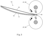
- step c shows the further processing of the pre-fixed arrangement 13 at the beginning of step c).
- the pre-set assembly 13 is passed through a roller assembly 18, pre-set side edge 19 first.
- the side view shows a heatable pair of rollers 21 consisting of two opposite rollers.
- the roller arrangement 18 shown can in particular be a calender roller arrangement.
- the roller assembly 18 has a plurality of pairs of rollers 20, 21 arranged side by side, the Roller assembly 18 comprises two heatable pairs of rollers 21 and nine non-heatable pairs of rollers 20.
- the passage of the prefixed assembly 13 through the roller assembly 18 is perpendicular to the axis on which the pairs of rollers 20, 21 are juxtaposed.
- the roller arrangement 18 shown can in particular be a calender roller arrangement.
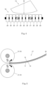
- Figure 12 shows a side view of the fixed assembly 17 emerging from the roller assembly 18 according to step c) of the method.
- the lack of fitting accuracy in the geometry of the two glass panes 11, 12 was compensated for by the rolling treatment.
- the two panes of glass 11, 12 now have the same curvature and are connected with a precise fit.
- the gap of the prefixed assembly 13 before the rolling treatment has disappeared.
- the rolling treatment is preferably a calender treatment.
- the formed fixed assembly 17 may be subjected to a de-airing process and heat and/or pressure treatment according to conventional methods to obtain the finished laminated glass.
Landscapes
- Physics & Mathematics (AREA)
- Engineering & Computer Science (AREA)
- Mechanical Engineering (AREA)
- Thermal Sciences (AREA)
- Fluid Mechanics (AREA)
- Joining Of Glass To Other Materials (AREA)
Description
- Die Erfindung betrifft ein Verfahren zur Herstellung eines Verbundglases oder einer Vorstufe davon.
- Ein Verbundglas bzw. eine Verbundglasscheibe besteht aus mindestens einer ersten Scheibe oder Außenscheibe, einer zweiten Scheibe oder Innenscheibe und einer polymeren Zwischenschicht, die die erste Scheibe mit der zweiten Scheibe verbindet. Verbundglas findet z.B. als Fahrzeugscheiben oder Fensterscheiben für Bauwerke Verwendung. Verbundglas kann planes oder gebogenes Verbundglas sein.
- Aus ökonomischen und ökologischen Gründen wird möglichst dünnes Verbundglas angestrebt. Unter dünnem Verbundglas wird hier ein Verbundglas verstanden, bei dem eine der beiden Glasscheiben eine Dicke von nicht mehr als 1,0 mm aufweist. Die andere Glasscheibe des Verbundglases kann Standardglasdicken aufweisen, in der Regel mit einer Dicke von mindestens 1,4 mm, z.B. 1,6 mm.
- Bekannte Verfahren zur Herstellung von Verbundglas umfassen üblicherweise das Anordnen von einer ersten Scheibe, einer oder mehreren Laminierfolien und einer zweiten Scheibe, die Entlüftung der erhaltenen Anordnung unter Bildung eines Vorverbunds und Wärme- und/oder Druckbehandlung des erhaltenen Vorverbunds, um die fertige Verbundglasscheibe zu erhalten. Sofern ein gebogenes Verbundglas hergestellt werden soll, ist es ferner erforderlich, die Glasscheiben vor der Bildung der Anordnung zu biegen.
- Gewöhnlich passen die verwendeten Glasscheiben in Krümmung und Form im Wesentlichen zueinander, so dass sie relativ passgenau zur Anordnung zusammengelegt und ausgerichtet werden können. Es gibt aber Fälle, bei denen die beiden Glasscheiben für die Herstellung des Verbundglases in der Geometrie eine fehlende Passgenauigkeit aufweisen, d.h. sich in der Krümmung und/oder in lokalen Bereichen in der Form unterscheiden. Dies kann sich z.B. aufgrund von Unzulänglichkeiten im Fertigungsprozess der verwendeten Glasscheiben ergeben oder prozesstechnisch bedingt sein.
- Eine fehlende Passgenauigkeit in der Geometrie der beiden Glasscheiben führt dazu, dass die sich beim Zusammenlegen der Scheiben ergebende Anordnung Zwischenräume bzw. Spalten aufweist, die Ausrichtung der Anordnung erschwert wird und sich Probleme bei den nachfolgenden Fertigungsschritten zur Herstellung des Verbundglases ergeben. Es versteht sich, dass diese Probleme umso größer werden, je stärker die fehlende Passgenauigkeit in der Geometrie ausgeprägt ist. Die Folgen können z.B. Fehler oder Ungenauigkeiten in der Ausrichtung der Scheiben im erhaltenen Verbundglas sein. Wenn die fehlende Passgenauigkeit zu ausgeprägt ist, ist es mit den bekannten Verfahren nach dem Stand der Technik nicht mehr möglich, die Scheiben mit der erforderlichen Präzision zueinander auszurichten.
-
EP 3189965 A1 betrifft eine laminierte Platte, die eine erste und zweite Scheibe umfasst, wobei die erste Scheibe dicker als die zweite Scheibe ist, die erste Scheibe im äußeren Umfang einen linear abgeschrägten Teil aufweist und die zweite Scheibe versetzt auf einer verlängerten Linie des linearen abgeschrägten Teils der ersten Scheibe positioniert ist. Die Krümmung der ersten und der zweiten Scheibe kann verschieden sein. -
FR 3012073 A1 -
GB 908338 A -
US 2007/223096 A1 beschreibt einen Reflektor, bei dem Komponenten eines Glaslaminats mit Klammern fixiert werden. -
DE 102006054736 A1 betrifft ein Verfahren zur Herstellung von Verbundglas, bei dem zwei Glasplatten mit je einer Folienschicht zu einem Glaspaket aufeinandergelegt werden und das Glaspaket zu einer Laminiervorrichtung transportiert und dort unter Vakuum und Aufschmelzen der Folienschicht zu Verbundglas laminiert wird, wobei das Glaspaket nach dem Aufeinanderlegen und vor dem Transport zumindest partiell erwärmt wird, um die Glasplatten relativ zur Folie zu fixieren. Bei der Fixierung kann mittels Andruckrollen ein Druck angelegt werden. -
DE 3728284 A1 beschreibt das Ausrichten zweier zu verbindender Glasscheiben mittels eines Ausrichttisches und Justieranschlägen. -
DE 4106958 A1 betrifft ein Verfahren zum Herstellen gekrümmter, miteinander verbundener Scheiben aus Glas mit einem zwischen den Scheiben eingelegten Abstandselement, wobei jede Scheibe mit einer Kontaktfläche in Kontakt gebracht wird und nach lagegenauer Ausrichtung relativ zu dieser Kontaktfläche mit ihr fest verbunden wird. - Der Erfindung liegt allgemein die Aufgabe zu Grunde, ein Verfahren zum Herstellen eines dünnen Verbundglases bereitzustellen, das die vorstehend erläuterten Nachteile bei den Verfahren nach dem Stand der Technik überwindet.
- Der Erfindung stellt sich insbesondere die Aufgabe ein Verfahren zum Herstellen eines dünnen Verbundglases bereitzustellen, das eine präzise und wiederholbare Ausrichtung und Fixierung der Anordnung der Glasscheiben unter Bildung einer fixierten Anordnung beim automatischen, halbautomatischen oder manuellen Zusammenbau des dünnen Verbundglases ermöglicht. Insbesondere soll das Verfahren für den Zusammenbau eines dünnen Verbundglases mit zwei Glasscheiben mit fehlender Passgenauigkeit in der Geometrie geeignet sein.
- Die Aufgabe wird erfindungsgemäß durch ein Verfahren nach Anspruch 1 gelöst. Bevorzugte Ausführungsformen der Erfindung gehen aus den abhängigen Ansprüchen hervor.
- Das erfindungsgemäße Verfahren ermöglicht die Ausrichtung und Fixierung der Anordnung von Glasscheiben mit fehlender Passgenauigkeit unter Bildung einer fixierten Anordnung für die Herstellung eines dünnen Verbundglases mit hoher Präzision und Wiederholbarkeit für die automatische, halbautomatische oder manuelle Fertigung.
- Das erfindungsgemäße Verfahren eignet sich insbesondere bei der Verwendung von zwei Glasscheiben, die eine fehlende Passgenauigkeit in der Geometrie besitzen. Die vorstehend beschriebenen Schwierigkeiten, die bei den bekannten Verfahren durch solche fehlende Passgenauigkeit verursacht werden, können durch das erfindungsgemäße Verfahren überwunden werden. Selbst Glasscheibenpaare mit starker Ausprägung der fehlenden Passgenauigkeit können in dem erfindungsgemäßen Verfahren verarbeitet werden.
- Durch das erfindungsgemäße Verfahren kann fehlende Passgenauigkeit teilweise verringert oder sogar ganz ausgeglichen werden und Fehler in der Ausrichtung im Verbundglas sind gegenüber herkömmlichen Verfahren deutlich verringert.
- Dementsprechend betrifft die Erfindung ein Verfahren zum Herstellen eines Verbundglases oder einer Vorstufe davon unter Verwendung einer ersten Glasscheibe mit einer Dicke von mindestens 1,4 mm und einer zweiten Glasscheibe mit einer Dicke von nicht mehr als 1,0 mm, wobei sich die erste Glasscheibe und die zweite Glasscheibe in der Krümmung und/oder in lokalen Bereichen in der Form unterscheiden und wobei das Verfahren folgende Schritte umfasst:
- a) das Ausrichten einer Anordnung, umfassend die erste Glasscheibe, die zweite Glasscheibe und mindestens eine zwischen der ersten und zweiten Glasscheibe befindliche Laminierfolie, durch Positionieren mindestens eines Seitenrandes der Anordnung an mindestens ein Anschlagelement;
- b) das Vorfixieren der ausgerichteten Anordnung an mindestens zwei Stellen an dem positionierten Seitenrand der Anordnung durch ein oder mehrere Fixierelemente und Erwärmen, wonach das oder die Fixierelemente wieder entfernt werden; und
- c) das Bilden einer fixierten Anordnung durch Hindurchleiten der vorfixierten Anordnung durch eine Walzenanordnung, insbesondere eine Kalanderwalzenanordnung, mit dem vorfixierten Seitenrand der Anordnung voraus, wobei die Anordnung während des Hindurchleitens zumindest abschnittsweise erwärmt wird.
- Im Folgenden wird die Erfindung im Einzelnen erläutert.
- Unter der Vorstufe von einem Verbundglas wird hier insbesondere die nach Schritt c) erhaltene fixierte Anordnung oder der entlüftete Vorverbund, der nach dem optionalen Entlüften der nach Schritt c) erhaltenen fixierten Anordnung erhalten wird, verstanden.
- Die Begriffe Krümmung bzw. Biegung und gekrümmt bzw. gebogen sind hier synonyme Begriffe.
- Unter einer Walzenanordnung ist eine Anordnung umfassend mindestens ein Rollenpaar aus zwei gegenüberliegenden Rollen zu verstehen.
- Das Verbundglas kann plan oder gebogen sein, wobei ein gebogenes Verbundglas bevorzugt ist. Das Verbundglas kann in einer oder in mehreren Richtungen des Raumes gebogen sein, wie es z.B. für Kraftfahrzeugscheiben üblich ist. Typische Krümmungsradien können z.B. im Bereich von etwa 20 mm bis etwa 40 m, bevorzugt 50 mm bis 30 m, liegen.
- In dem erfindungsgemäßen Verfahren wird eine erste Glasscheibe mit einer Dicke von mindestens 1,4 mm und eine zweite Glasscheibe mit einer Dicke von nicht mehr als 1,0 mm verwendet. Das Verfahren betrifft somit die Herstellung eines dünnen Verbundglases. Die erste Glasscheibe kann plan oder gekrümmt sein. Die zweite Glasscheibe kann plan oder gekrümmt sein. Glasscheiben können z.B. durch ein Schwerkraftbiegeverfahren gekrümmt werden.
- Die verwendete erste Glasscheibe und die verwendete zweite Glasscheibe unterscheiden sich in der Krümmung und/oder in lokalen Bereichen in der Form. Wie bereits erwähnt stellt dies eine fehlende Passgenauigkeit in der Geometrie der beiden Glasscheiben dar, die zum Verbundglas laminiert werden sollen. Diese Unterschiede in der Krümmung und/oder in lokalen Bereichen in der Form führen gewöhnlich zur Ausbildung von Zwischenräumen oder Spalten in der Anordnung, wenn die beiden Glasscheiben mit der mindestens einen Laminierfolie dazwischen zu der Anordnung übereinandergelegt werden.
- Bei einer unterschiedlichen Krümmung kann die erste Glasscheibe eine stärkere Krümmung aufweisen als die zweite Glasscheibe und umgekehrt. Eine unterschiedliche Krümmung der ersten und zweiten Glasscheibe schließt auch Fälle ein, bei der eine der beiden Glasscheiben plan ist und die andere gekrümmt ist. Der Unterschied in der Krümmung der beiden Glasscheiben kann beträchtlich sein.
- Unterschiede der verwendeten ersten Glasscheibe und zweiten Glasscheibe in lokalen Bereichen in der Form stellen lokale Formabweichungen oder Formdefekte dar. Es kann sich dabei beispielsweise um Ausbuchtungen, Wellen oder Vertiefungen sowie Uneinheitlichkeiten in der Dicke handeln, die in der oder den Glasscheiben vorhanden sind. Diese können z.B. prozesstechnisch bedingt sein oder sich durch Fehler im Herstellungsprozess ergeben. Solche Fehler in lokalen Bereichen in der Form können auch bei Verwendung von zwei planen Glasscheiben zu fehlender Passgenauigkeit in der Geometrie führen.
- In bevorzugten Ausführungsformen liegt eine unterschiedliche Krümmung der ersten und zweiten Glasscheibe vor, wobei gegebenenfalls zusätzlich in lokalen Bereichen Unterschiede in der Form bestehen.
- In einer besonders bevorzugten Ausführungsform ist die verwendete erste Glasscheibe gekrümmt und die verwendete zweite Glasscheibe ist nicht gekrümmt bzw. plan oder weist eine geringere Krümmung als die erste Glasscheibe auf. Der Unterschied in der Krümmung der beiden Glasscheiben kann dabei beträchtlich sein. In extremen Fällen weist die dünnere zweite Glasscheibe keine Krümmung auf und die dickere erste Glasscheibe weist eine Krümmung auf, die so gestaltet ist, dass das finale Produkt (Verbundglas) möglichst genau mit der gewünschten CAD-Form (computer-aided-design-Form) übereinstimmt.
- Die erste Glasscheibe weist bevorzugt eine Dicke im Bereich von 1,4 mm bis 5,0 mm, bevorzugter von 1,6 mm bis 2,2 mm, auf. Die zweite Glasscheibe weist bevorzugt eine Dicke im Bereich von 0,3 bis 1,0 mm, bevorzugter von 0,5 bis 0,8 mm, auf.
- Die erste Glasscheibe und die zweite Glasscheibe können aus dem gleichen Material oder aus verschiedenem Material sein. Die Glasscheiben können aus anorganischem Glas und/oder organischem Glas, d.h. organischen Polymeren, gebildet sein. In einer bevorzugten Ausführungsform sind die erste Glasscheibe und/oder die zweite Glasscheibe aus Flachglas, Quarzglas, Borosilikatglas, Kalk-Natron-Glas, Alkalialuminosilikatglas, Polycarbonat und/oder Polymethacrylat gebildet.
- Die erste und/oder zweite Glasscheibe können aus nicht vorgespanntem Glas, thermisch oder chemisch teilvorgespanntem Glas (TVG) oder thermisch (ESG) oder chemisch vorgespanntem Glas gebildet sein.
- Für die Erstellung der Anordnung wird mindestens eine Laminierfolie verwendet, die sich in der Anordnung zwischen der ersten und zweiten Glasscheibe befindet. Die mindestens eine Laminierfolie ist insbesondere eine Polymerfolie, bevorzugt eine thermoplastische Polymerfolie. Es werden in der Regel eine oder mehrere Laminierfolien verwendet. Die mindestens eine Laminierfolie dient zum Verbinden der ersten Glasscheibe und der zweiten Glasscheibe durch Verkleben, um das Laminat bzw. Verbundglas zu bilden.
- Es können eine oder mehrere Laminierfolien, z.B. 1, 2 oder 3 Laminierfolien, verwendet werden. Solche Laminierfolien sind dem Fachmann gut bekannt und im Handel erhältlich. Die Laminierfolie, z.B. eine PVB-Folie, weist z.B. eine Dicke von 0,1 bis 2 mm und bevorzugter von 0,3 bis 1 mm auf, typischerweise 0,38 mm oder 0,76 mm oder 0,81 mm oder 0,84 mm.
- Die Laminierfolie kann z.B. aus Polyvinylbutyral (PVB), Ethylenvinylacetat (EVA), Polyurethan, einem Copolymer davon, einem Derivat davon oder Mischungen davon gebildet sein, wobei PVB-Folien besonders bevorzugt sind. Neben dem Polymer kann die Laminierfolie gegebenenfalls übliche Additive, wie z.B. Weichmacher oder Füllstoffe, enthalten.
- Neben der mindestens einen Laminierfolie können für die Anordnung gegebenenfalls eine oder mehrere, von der Laminierfolie verschiedene zusätzliche Polymerfolien eingesetzt werden, die ebenfalls zwischen der ersten und zweiten Glasscheibe angeordnet werden, z.B. eine infrarotreflektierende Polymerfolie, z.B. eine Polyesterfolie, die gegebenenfalls eine Beschichtung aufweist, z.B. aus Silber.
- Zur Bildung der Anordnung, umfassend die erste Glasscheibe, die zweite Glasscheibe und mindestens eine zwischen der ersten und zweiten Glasscheibe befindliche Laminierfolie, werden die erste Glasscheibe, die mindestens eine Laminierfolie und die zweite Glasscheibe übereinandergelegt. Wie gesagt können gegebenenfalls eine oder mehrere zusätzliche Polymerfolien zwischen den beiden Glasscheiben angeordnet werden.
- Das erfindungsgemäße Verfahren umfasst als Schritt a) das Ausrichten der Anordnung, umfassend die erste Glasscheibe, die zweite Glasscheibe und die mindestens eine zwischen der ersten und zweiten Glasscheibe befindliche Laminierfolie, durch Positionieren mindestens eines Seitenrandes der Anordnung an mindestens ein Anschlagelement.
- Die Ausrichtung der Anordnung ist ein übliches Verfahren bei der Herstellung von Verbundgläsern und der Fachmann ist mit den erforderlichen Maßnahmen vertraut. Es können abhängig von der Art der Anschlagelemente ein oder mehrere Anschlagelemente verwendet werden, zweckmäßigerweise mindestens drei. Es können alle üblichen Anschlagelemente verwendet werden, z.B. vertikal aufgestellte Zylinder, die am Boden oder einer üblichen Anschlagvorrichtung in der gewünschten Anordnung fixiert sind.
- Zur Ausrichtung wird mindestens ein Seitenrand der Anordnung an mindestens ein Anschlagelement positioniert, indem der Seitenrand gegen das Anschlagelement gedrückt wird, so dass der Seitenrand an dem Anschlagelement anliegt. Grundsätzlich kann ein beliebiger Seitenrand zum Positionieren an dem Anschlagelement ausgewählt werden, zweckmäßigerweise wird aber der Seitenrand mit der größten Bedeutung gewählt, da an dem positionierten Seitenrand die höchste Genauigkeit in der Ausrichtung erreicht wird. Bei Seitenfenstern für Autos ist z.B. der Seitenrand mit der größten Bedeutung der obere Seitenrand, da dieser im eingebauten Zustand sichtbar sein kann.
- In der Regel ist es bevorzugt, dass mindestens zwei, gewöhnlich mindestens drei, Anschlagelemente so angeordnet sind, dass der vorzufixierende Seitenrand an mindestens einem, bevorzugt mindestens zwei Anschlagelementen positioniert werden kann, und ein den vorzufixierenden Seitenrand berührender Seitenrand an mindestens einem Anschlagelement positioniert werden kann, um eine genaue Ausrichtung zu erreichen.
- In einer bevorzugten Ausführungsform werden zum Ausrichten der Anordnung mindestens drei Anschlagelemente eingesetzt, die so angeordnet sind, dass der vorzufixierende Seitenrand der Anordnung an mindestens zwei Anschlagelementen positioniert wird und ein anderer, den vorzufixierenden Seitenrand berührender Seitenrand der Anordnung an mindestens einem Anschlagelement positioniert wird. Eine solche Ausführungsform ist in
Fig. 2 veranschaulicht. - Nach dem Ausrichten erfolgt in Schritt b) das Vorfixieren der ausgerichteten Anordnung an zwei oder mehr Stellen an dem positionierten Seitenrand der Anordnung durch ein oder mehrere, gewöhnlich mindestens zwei, Fixierelemente und Erwärmen.
- Das Fixierelement kann gegebenenfalls beheizbar sein. Als Fixierelement können alle, dem Fachmann vertrauten Mittel zur mechanischen Fixierung verwendet werden. Bei dem Fixierelement kann es sich z.B. um eine Klammer handeln. Die Klammer kann beheizbar sein. Durch das Fixierelement kann eine Kraft senkrecht zur Glasoberfläche aufgebracht werden.
- An den mindestens zwei Stellen an dem positionierten Seitenrand werden das oder die Fixierelemente angebracht und die Stellen werden punktuell bzw. lokal unter Aufbringung einer Kraft normal zur Glasoberfläche erwärmt, wodurch die Vorfixierung der Anordnung erreicht wird. Die punktuelle Erwärmung an den besagten Stellen kann z.B. durch Heißluft und/oder ein oder mehrere beheizte Fixierelemente, insbesondere beheizte Klammern, erfolgen. Zur Erzeugung der Heißluft können z.B. Heißluftgebläse verwendet werden.
- Durch die punktuelle Erwärmung der mindestens zwei Stellen wird die Laminierfolie an diesen Stellen klebfähig, so dass durch die lokale Verklebung die Vorfixierung erreicht wird. Die zweckmäßige Temperatur hängt naturgemäß von der Art der eingesetzten Laminierfolie ab. Die Anordnung wird an den zu fixierenden Stellen z.B. auf eine Temperatur im Bereich von 30 °C bis 140 °C, bevorzugt von 40 °C bis 100 °C, erwärmt. Da die Zeit zur Erwärmung möglichst kurz gehalten werden soll, ist die Temperatur der Heißluft und/oder der beheizten Fixierelemente meist deutlich höher, um die gewünschte Temperatur in der Anordnung möglichst schnell zu erreichen.
- Nach der Vorfixierung der Anordnung werden das oder die Fixierelemente wieder von der Anordnung entfernt, wodurch die vorfixierte Anordnung erhalten wird.
- Anschließend erfolgt in Schritt c) das Bilden einer fixierten Anordnung durch Hindurchleiten der vorfixierten Anordnung durch eine Walzenanordnung mit dem vorfixierten Seitenrand der Anordnung voraus, wobei die Anordnung während des Hindurchleitens zumindest abschnittsweise erwärmt wird.
- Bevorzugt weist die eingesetzte Walzenanordnung mehrere nebeneinander angeordnete Rollenpaare aus zwei einander gegenüberliegenden Rollen auf, wobei gegebenenfalls mindestens ein Rollenpaar beheizbar ist.
- Besonders bevorzugt handelt es sich bei der Walzenanordnung um eine Kalanderwalzenanordnung. Diese weist bevorzugt mehrere nebeneinander angeordnete Rollenpaare aus zwei einander gegenüberliegenden Rollen auf, wobei gegebenenfalls mindestens ein Rollenpaar beheizbar ist.
- Die Anordnung wird während des Hindurchleitens zumindest abschnittsweise erwärmt. In den erwärmten Abschnitten der Anordnung werden die beiden Glasscheiben durch die dort klebfähige Laminierfolie verbunden, wodurch die fixierte Anordnung erhalten wird. Es ist insbesondere bevorzugt, dass die Anordnung während des Hindurchleitens nur abschnittsweise, also nicht vollflächig sondern teilflächig bzw. streifenweise, erwärmt wird. Auf diese Weise wird die Anordnung nicht vollflächig, sondern lediglich abschnittsweise verbunden, wodurch eine im Anschluss gegebenenfalls durchgeführte Entlüftung erleichtert wird.
- Die zumindest abschnittsweise vorfixierte Anordnung wird in Schritt c) bevorzugt durch Heißluft und/oder ein oder mehrere beheizte Rollenpaare der Walzenanordnung, insbesondere Kalanderwalzenanordnung, erwärmt. Zur Erzeugung der Heißluft können z.B. Heißluftgebläse verwendet werden. Die zweckmäßige Temperatur hängt naturgemäß von der Art der eingesetzten Laminierfolie ab. Die Anordnung wird in Schritt c) zumindest abschnittsweise, bevorzugt nur abschnittsweise, z.B. auf eine Temperatur im Bereich von 30 °C bis 140 °C, bevorzugt von 40 °C bis 100 °C, erwärmt.
- In einer bevorzugten Ausführungsform erfolgt eine abschnittsweise bzw. streifenweise Erwärmung der vorfixierten Anordnung durch Verwendung einer Walzenanordnung, insbesondere einer Kalanderwalzenanordnung, mit mehreren nebeneinander angeordneten Rollenpaaren, wobei ein Teil der Rollenpaare nicht beheizt wird und mindestens ein Rollenpaar beheizt wird. Sofern zwei oder mehr Rollenpaare beheizt werden, befindet sich jeweils zwischen zwei beheizten Rollenpaaren bevorzugt mindestens ein nicht beheiztes Rollenpaar.
- Der auf die vorfixierte Anordnung in der Walzenanordung, insbesondere Kalanderwalzenanordnung, ausgeübte Anpressdruck, relativ zu dem atmosphärischen Druck, kann z.B. 2 bis 5 bar, bevorzugt 3 bis 4 bar, betragen.
- Durch das Hindurchleiten der vorfixierten Anordnung durch die Walzenanordnung, die insbesondere als Kalanderwalzenanordnung ausgebildet sein kann, unter zumindest abschnittweisen, bevorzugt abschnittsweisen, Erwärmen, wird die fixierte Anordnung gebildet.
- Durch das Hindurchleiten der vorfixierten Anordnung durch die Walzenanordnung, die insbesondere als Kalanderwalzenanordnung ausgebildet sein kann, kann sich ein weiterer Effekt ergeben. Dieser besteht darin, dass die fehlende Passgenauigkeit in der Geometrie der beiden Glasscheiben ausgeglichen werden kann. Insbesondere können vorher bestehende Unterschiede in der Krümmung der beiden Glasscheiben ausgeglichen werden. In einer bevorzugten Ausführungsform werden bestehende Unterschiede in der Krümmung der ersten und zweiten Glasscheibe durch die Behandlung in Schritt c) ausgeglichen, indem die Krümmung der dünneren zweiten Glasscheibe ganz oder teilweise an die Krümmung der dickeren ersten Glasscheibe angepasst wird.
- Das erfindungsgemäße Verfahren kann ferner gegebenenfalls und bevorzugt einen Entlüftungsschritt umfassen, bei dem die in Schritt c) erhaltene fixierte Anordnung einem Entlüftungsprozess unter Bildung eines Vorverbunds unterworfen wird. Die Entlüftung kann nach den bekannten Verfahren erfolgen, z.B. durch eine Kalanderbehandlung oder durch ein Vakuumverfahren, wobei ein Vakuumverfahren bevorzugt ist. Beim Vakuumverfahren wird an die fixierte Anordnung, die z.B. in einen Vakuumsack oder einem Vakuumrahmen platziert wurde, ein Vakuum angelegt und Restluft aus der fixierten Anordnung evakuiert. Bei dem Entlüftungsprozess, bevorzugt durch das Vakuumverfahren, erfolgt in der Regel auch eine Erwärmung der fixierten Anordnung.
- Das erfindungsgemäße Verfahren kann ferner gegebenenfalls und bevorzugt eine Wärme- und/oder Druckbehandlung des nach der Entlüftung erhaltenen Vorverbunds umfassen, um das Verbundglas fertigzustellen.
- Diese Wärme- und/oder Druckbehandlung des nach der Entlüftung erhaltenen Vorverbundes zur Bildung des Verbundglases kann nach irgendeinem der dem Fachmann gut bekannten Verfahren durchgeführt werden, wobei das Autoklavverfahren bevorzugt ist.
- Das Verbundglas ist bevorzugt eine Fahrzeugscheibe, besonders bevorzugt eine Kraftfahrzeugscheibe. Das Fahrzeug kann ein Land-, Schiffs- oder Luftfahrzeug sein, insbesondere ein Personenkraftwagen. Das Verbundglas ist bevorzugt eine Seitenscheibe für ein Fahrzeug, bevorzugt für ein Kraftfahrzeug.
- Die Erfindung wird nachfolgend anhand von nicht einschränkenden Ausführungsbeispielen unter Bezug auf die beigefügten Zeichnungen näher erläutert.
- In diesen zeigen:
- Fig. 1
- schematisch eine Seitenansicht der ausgerichteten bzw. vorfixierten Anordnung in Schritt a) und b) des Verfahrens;
- Fig. 2
- schematisch eine Draufsicht auf die ausgerichtete Anordnung während des Vorfixierens in Schritt b) des Verfahrens;
- Fig. 3
- schematisch eine Seitenansicht der vorfixierten Anordnung zu Beginn von Schritt c) des Verfahrens;
- Fig. 4
- schematisch eine Draufsicht auf die vorfixierte Anordnung zu Beginn von Schritt c) des Verfahrens;
- Fig. 5
- schematisch eine Seitenansicht der Anordnung bzw. der fixierten Anordnung gegen Ende von Schritt c) des Verfahrens.
-
Fig. 1 zeigt schematisch eine Seitenansicht der Anordnung 13, umfassend eine erste Glasscheibe 11, eine zweite Glasscheibe 12 und eine Laminierfolie 14, z.B. aus PVB, während der Schritte a) und b) des Verfahrens, für die Herstellung einer Fahrzeugfensterscheibe. Die erste Glasscheibe 11 weist eine Dicke von 1,6 mm und eine deutliche Krümmung auf. Die Laminierfolie 14 befindet sich zwischen der ersten Glasscheibe 11 und der zweiten Glasscheibe 12. Die zweite Glasscheibe 12 weist eine Dicke von nicht mehr als 1,0 mm, z.B. 0,6 mm, auf und ist plan bzw. nicht gekrümmt. Aufgrund der unterschiedlichen Krümmung weisen die Glasscheiben 11, 12 eine fehlende Passgenauigkeit in der Geometrie auf. Dadurch bildet sich ein Spalt in der Anordnung 13. - Die obere Abbildung von
Fig. 1 zeigt die Ausrichtung der Anordnung 13 durch Positionierung des Seitenrandes 19 der Anordnung 13 an einem Ausrichtelement 15. Die mittlere Abbildung vonFig. 1 zeigt schematisch die Vorfixierung einer Stelle des Seitenrandes 19 mit einer an dieser Stelle angebrachten beheizbaren Klammer als beheizbares Fixierelement 16 zur punktuellen Erwärmung der Anordnung 13. Die untere Abbildung vonFig. 1 zeigt die vorfixierte Anordnung 13 mit der verbundenen Stelle am Seitenrand 19. -
Fig. 2 zeigt eine Draufsicht auf die ausgerichtete Anordnung 13 inFig. 1 . Es ist ersichtlich, dass der Seitenrand 19 an zwei zylinderförmigen Anschlagelementen 15 positioniert ist und ein weiterer, den Seitenrand 19 berührender Seitenrand an einem dritten zylinderförmigen Anschlagelement 15 positioniert ist, wodurch die Anordnung 13 ausgerichtet worden ist. An der ausgerichteten Anordnung 13 sind an zwei Stellen an dem an den zwei Anschlagelementen positionierten Seitenrand 19 beheizbare Klammern als beheizbares Fixierelement 16 angebracht. Durch die beheizten Klammern können die zwei Stellen lokal verbunden werden, um die Vorfixierung zu erhalten. -
Fig. 3 zeigt die Weiterverarbeitung der vorfixierten Anordnung 13 zu Beginn von Schritt c). Die vorfixierte Anordnung 13 wird mit dem vorfixierten Seitenrand 19 voraus durch eine Walzenanordnung 18 geleitet. Die Seitenansicht zeigt ein beheizbares Rollenpaar 21 aus zwei einander gegenüberliegenden Rollen. Die inFig. 3 gezeigte Walzenanordnung 18 kann insbesondere eine Kalanderwalzenanordnung sein. -
Fig. 4 zeigt das Gleiche wieFig. 3 in der Draufschicht. Die Walzenanordnung 18 weist mehrere nebeneinander angeordnete Rollenpaare 20, 21 auf, wobei die Walzenanordnung 18 zwei beheizbare Rollenpaare 21 und neun nicht beheizbare Rollenpaare 20 umfasst. Die Leitung der vorfixierten Anordnung 13 durch die Walzenanordnung 18 erfolgt senkrecht zu der Achse, auf der die Rollenpaare 20, 21 nebeneinander angeordnet sind. Die inFig. 4 gezeigte Walzenanordnung 18 kann insbesondere eine Kalanderwalzenanordnung sein. -
Fig. 5 zeigt eine Seitenansicht der aus der Walzenanordnung 18 herauskommenden fixierten Anordnung 17 gemäß Schritt c) des Verfahrens. Durch die Walzbehandlung wurde die fehlende Passgenauigkeit in der Geometrie der beiden Glasscheiben 11, 12 ausgeglichen. Die beiden Glasscheiben 11, 12 weisen nun dieselbe Krümmung auf und sind passgenau verbunden. Der Spalt der vorfixierten Anordnung 13 vor der Walzbehandlung ist verschwunden. Bevorzugt handelt es sich bei der Walzbehandlung um eine Kalanderbehandlung. - Die gebildete fixierte Anordnung 17 kann gemäß den üblichen Verfahren einem Entlüftungsverfahren und einer Wärme- und/oder Druckbehandlung unterworfen werden, um das fertige Verbundglas zu erhalten.
-
- 11
- erste Glasscheibe
- 12
- zweite Glasscheibe
- 13
- Anordnung
- 14
- Laminierfolie
- 15
- Anschlagelement
- 16
- Fixierelement
- 17
- Fixierte Anordnung
- 18
- Walzenanordnung
- 19
- Seitenrand
- 20
- Rollenpaar
- 21
- Beheizbares Rollenpaar
Claims (14)
- Verfahren zum Herstellen eines Verbundglases oder einer Vorstufe davon unter Verwendung einer ersten Glasscheibe (11) mit einer Dicke von mindestens 1,4 mm und einer zweiten Glasscheibe (12) mit einer Dicke von nicht mehr als 1,0 mm, wobei sich die erste Glasscheibe (11) und die zweite Glasscheibe (12) in der Krümmung und/oder in lokalen Bereichen in der Form unterscheiden und wobei das Verfahren folgende Schritte umfasst:a) das Ausrichten einer Anordnung (13), umfassend die erste Glasscheibe (11), die zweite Glasscheibe (12) und mindestens eine zwischen der ersten und zweiten Glasscheibe befindliche Laminierfolie (14), durch Positionieren mindestens eines Seitenrandes (19) der Anordnung (13) an mindestens ein Anschlagelement (15);b) das Vorfixieren der ausgerichteten Anordnung (13) an mindestens zwei Stellen an dem positionierten Seitenrand (19) der Anordnung (13) durch ein oder mehrere Fixierelemente (16) und Erwärmen, wonach das oder die Fixierelemente (16) wieder entfernt werden; undc) das Bilden einer fixierten Anordnung (17) durch Hindurchleiten der vorfixierten Anordnung (13) durch eine Walzenanordnung (18) umfassend mindestens ein Rollenpaar (20) aus zwei gegenüberliegenden Rollen mit dem vorfixierten Seitenrand (19) der Anordnung (13) voraus, wobei die Anordnung (13) während des Hindurchleitens zumindest abschnittsweise erwärmt wird.
- Verfahren nach Anspruch 1, wobei die verwendete erste Glasscheibe (11) gekrümmt ist und die verwendete zweite Glasscheibe (12) nicht gekrümmt ist oder eine geringere Krümmung als die erste Glasscheibe (11) aufweist.
- Verfahren nach einem der vorherigen Ansprüche, wobei die erste Glasscheibe (11) eine Dicke im Bereich von 1,4 mm bis 5,0 mm, besonders bevorzugt von 1,6 mm bis 2,2 mm, und/oder die zweite Glasscheibe (12) eine Dicke im Bereich von 0,3 bis 1,0 mm, bevorzugt von 0,5 bis 0,8 mm, aufweist.
- Verfahren nach einem der vorherigen Ansprüche, wobei das Fixierelement (16) eine Klammer ist, die gegebenenfalls beheizbar ist.
- Verfahren nach einem der vorherigen Ansprüche, wobei die Walzenanordnung (18) mehrere nebeneinander angeordnete Rollenpaare (20) aus zwei einander gegenüberliegenden Rollen aufweist, wobei gegebenenfalls mindestens ein Rollenpaar beheizbar ist.
- Verfahren nach einem der vorherigen Ansprüche, wobei die Erwärmung in Schritt b) durch Heißluft und/oder ein oder mehrere beheizte Fixierelemente (16), insbesondere beheizte Klammern, erfolgt.
- Verfahren nach einem der vorherigen Ansprüche, wobei die zumindest abschnittsweise Erwärmung der vorfixierten Anordnung (13) in Schritt c) durch Heißluft und/oder ein oder mehrere beheizte Rollenpaare (21) der Walzenanordnung (18) erfolgt.
- Verfahren nach einem der vorherigen Ansprüche, wobei die Anordnung (13) in Schritt b) an den zu fixierenden Stellen auf eine Temperatur im Bereich von 30 °C bis 140 °C, bevorzugt von 40 °C bis 100 °C, erwärmt wird und/oder wobei die Anordnung (13) in Schritt c) zumindest abschnittsweise auf eine Temperatur im Bereich von 30 °C bis 140 °C, bevorzugt von 40 °C bis 100 °C, erwärmt wird.
- Verfahren nach einem der vorherigen Ansprüche, ferner umfassend einen Entlüftungsschritt, bei dem die in Schritt c) erhaltene fixierte Anordnung (17) einem Entlüftungsprozess unter Bildung eines Vorverbunds unterworfen wird, wobei die Entlüftung bevorzugt durch ein Vakuumverfahren erfolgt.
- Verfahren nach Anspruch 9, ferner umfassend eine Wärme- und/oder Druckbehandlung des nach dem Entlüftungsprozess erhaltenen Vorverbunds zur Bildung des Verbundglases.
- Verfahren nach einem der vorherigen Ansprüche, wobei in Schritt c) die Anordnung (13) während des Hindurchleitens durch die Walzenanordnung (18) abschnittsweise erwärmt wird.
- Verfahren nach einem der vorherigen Ansprüche, wobei die Walzenanordnung (18) eine Kalanderwalzenanordnung ist.
- Verfahren nach einem der vorherigen Ansprüche, wobei das Verbundglas eine Fahrzeugscheibe, bevorzugt eine Kraftfahrzeugscheibe, insbesondere eine Seitenscheibe für ein Fahrzeug, ist.
- Verfahren nach einem der vorherigen Ansprüche, wobei das Verbundglas ein gebogenes Verbundglas ist.
Applications Claiming Priority (2)
| Application Number | Priority Date | Filing Date | Title |
|---|---|---|---|
| EP17197145 | 2017-10-18 | ||
| PCT/EP2018/076100 WO2019076597A1 (de) | 2017-10-18 | 2018-09-26 | Verbessertes ausrichtungs- und verbundverfahren für die herstellung von dünnem verbundglas aus glasscheiben mit fehlender passgenauigkeit |
Publications (2)
| Publication Number | Publication Date |
|---|---|
| EP3697612A1 EP3697612A1 (de) | 2020-08-26 |
| EP3697612B1 true EP3697612B1 (de) | 2023-02-22 |
Family
ID=60143561
Family Applications (1)
| Application Number | Title | Priority Date | Filing Date |
|---|---|---|---|
| EP18773199.7A Active EP3697612B1 (de) | 2017-10-18 | 2018-09-26 | Verbessertes ausrichtungs- und verbundverfahren für die herstellung von dünnem verbundglas aus glasscheiben mit fehlender passgenauigkeit |
Country Status (6)
| Country | Link |
|---|---|
| US (1) | US11511526B2 (de) |
| EP (1) | EP3697612B1 (de) |
| CN (1) | CN109937139B (de) |
| MX (1) | MX2020003902A (de) |
| PL (1) | PL3697612T3 (de) |
| WO (1) | WO2019076597A1 (de) |
Families Citing this family (1)
| Publication number | Priority date | Publication date | Assignee | Title |
|---|---|---|---|---|
| WO2020112431A1 (en) * | 2018-11-29 | 2020-06-04 | Corning Incorporated | Method and system for roll-forming and laminating cover glass using pressure rollers |
Family Cites Families (18)
| Publication number | Priority date | Publication date | Assignee | Title |
|---|---|---|---|---|
| NL255626A (de) | 1959-09-22 | |||
| US3444732A (en) * | 1967-06-06 | 1969-05-20 | Albert L Robbins | Method and apparatus for determining optimum bonding parameters for thermoplastic material |
| US3826701A (en) * | 1972-10-31 | 1974-07-30 | Us Army | Controllable heat sealing process for optimum seal strength |
| US3925139A (en) * | 1974-01-10 | 1975-12-09 | Package Machinery Co | Seal monitoring apparatus |
| DE3728284A1 (de) | 1987-08-25 | 1989-04-27 | Flachglas Ag | Konfektioniervorrichtung |
| DE4106958A1 (de) | 1991-03-05 | 1992-09-10 | Rudolf Grenzebach | Verfahren und vorrichtung zum herstellen gekruemmter, miteinander verbundener scheiben |
| US7704342B2 (en) * | 2001-12-27 | 2010-04-27 | Solutia, Inc. | Glass lamination process |
| FI118003B (fi) | 2004-11-09 | 2007-05-31 | Tamglass Ltd Oy | Menetelmä ja laite lasilevyjen laminoimiseksi |
| US7871664B2 (en) | 2006-03-23 | 2011-01-18 | Guardian Industries Corp. | Parabolic trough or dish reflector for use in concentrating solar power apparatus and method of making same |
| DE102006054736A1 (de) | 2006-11-21 | 2008-05-29 | Armatec Vierhaus Gmbh | Verfahren zur Herstellung von Verbundglasscheiben |
| JP5521458B2 (ja) * | 2009-09-16 | 2014-06-11 | セントラル硝子株式会社 | 合わせガラスの予備接着装置 |
| FR3012073A1 (fr) | 2013-10-23 | 2015-04-24 | Saint Gobain | Vitrage feuillete asymetrique |
| CN106414065B (zh) * | 2014-05-06 | 2019-04-09 | 法国圣戈班玻璃厂 | 具有边界密封物的复合玻璃板及其制造方法 |
| RU2709271C2 (ru) * | 2014-09-30 | 2019-12-17 | Секисуй Кемикал Ко., Лтд. | Межслойная пленка для ламинированного стекла и ламинированное стекло |
| JP6720741B2 (ja) * | 2015-08-07 | 2020-07-08 | Agc株式会社 | 積層板および中間膜 |
| US20190061324A1 (en) * | 2015-10-30 | 2019-02-28 | Sp Advanced Engineering Materials Pvt. Ltd. | Glass laminates and a process for manufacturing thereof |
| KR102004892B1 (ko) * | 2015-12-14 | 2019-10-01 | 쌩-고벵 글래스 프랑스 | 복합 판유리를 오토클레이브 없이 라미네이팅하는 방법 |
| JP6787066B2 (ja) * | 2016-01-05 | 2020-11-18 | Agc株式会社 | 積層板 |
-
2018
- 2018-09-26 MX MX2020003902A patent/MX2020003902A/es unknown
- 2018-09-26 CN CN201880002238.4A patent/CN109937139B/zh not_active Expired - Fee Related
- 2018-09-26 EP EP18773199.7A patent/EP3697612B1/de active Active
- 2018-09-26 US US16/757,132 patent/US11511526B2/en active Active
- 2018-09-26 PL PL18773199.7T patent/PL3697612T3/pl unknown
- 2018-09-26 WO PCT/EP2018/076100 patent/WO2019076597A1/de not_active Ceased
Also Published As
| Publication number | Publication date |
|---|---|
| CN109937139B (zh) | 2023-04-28 |
| US11511526B2 (en) | 2022-11-29 |
| EP3697612A1 (de) | 2020-08-26 |
| US20200247093A1 (en) | 2020-08-06 |
| CN109937139A (zh) | 2019-06-25 |
| MX2020003902A (es) | 2020-08-20 |
| PL3697612T3 (pl) | 2023-05-22 |
| WO2019076597A1 (de) | 2019-04-25 |
Similar Documents
| Publication | Publication Date | Title |
|---|---|---|
| EP0877664B2 (de) | Verfahren zur herstellung einer von verwerfungsbedingten optischen störungen freien verbundsicherheitsglasscheibe, verwendung einer besonderen trägerfolie für die herstellung der verbundsicherheitsglasscheibe sowie für das verfahren bzw. die verwendung besonders geeignete trägerfolien | |
| DE69923155T2 (de) | Verfahren zur Herstellung von Leichtverglasungen unter Verwendung von mehrschichtigen Glas/Kunstoff-Verbünden | |
| EP3600882B1 (de) | Vorrichtung und verfahren zum aufnehmen, verformen und ablegen einer dünnen glasscheibe | |
| EP0975463B1 (de) | Verfahren zur herstellung einer gebogenen verbundsicherheitsglasscheibe | |
| EP3544809B1 (de) | Verfahren zur herstellung einer gebogenen verbundglasscheibe mit einer dünnen glasscheibe | |
| EP1235683B1 (de) | Verfahren und folie zur herstellung von verbundsicherheitsscheiben | |
| DE202016009099U1 (de) | Kaltgeformte Laminate | |
| EP3691893A1 (de) | Verbundglasscheibe mit angefastem durchgangsloch | |
| DE112020002902T5 (de) | Laminierte Verglasung mit kleinen Radien in komplexer Form | |
| DE3726033C2 (de) | Verfahren und Vorrichtung zum Biegen thermoplastischer Scheiben und zur Herstellung laminierter lichtdurchlassender Tafeln | |
| WO2017102656A1 (de) | Verfahren zur autoklavfreien lamination einer verbundscheibe | |
| EP2261030B1 (de) | Verfahren zur Herstellung einer Verbundglasscheibe | |
| DE102004003328A1 (de) | Verfahren zum Herstellen eines gewölbten Karosserieelements mit Solarzellen | |
| DE202019104803U1 (de) | Gebogene Fahrzeug-Verbundscheibe mit einer Funktionsfolie | |
| DE19519504C2 (de) | Verfahren zum Herstellen gebogener Verbundglasscheiben | |
| DE69710660T2 (de) | Verbundverglasung mit Abstandshalter | |
| EP3697612A1 (de) | Verbessertes ausrichtungs- und verbundverfahren für die herstellung von dünnem verbundglas aus glasscheiben mit fehlender passgenauigkeit | |
| DE3315330A1 (de) | Verfahren zur herstellung eines gekruemmten glas-kunststoff-laminats | |
| EP0457209A2 (de) | Verfahren zur Herstellung einer Folie aus thermoplastischem Kunststoff, Folie, hergestellt nach dem Verfahren, und Verbundsicherheitsglas, hergestellt unter Verwendung der Folie | |
| EP2647497A1 (de) | Verfahren zur Herstellung einer gewölbten Verbundscheibe mit vorgeformter Polymerfolie | |
| DE102020102375A1 (de) | Verbundglasscheibe, insbesondere zum Einsatz in Kraftfahrzeugen | |
| DE202016008420U1 (de) | Verbundscheibe | |
| DE879166C (de) | Verfahren zum Herstellen von Mehrschichtenglas mit in die Zwischenschicht eingelegten Verstaerkungsdraehten | |
| DE202019106306U1 (de) | Glasscheibe mit Metallelement und Klebefläche zur Verklebung von polymeren Anbauteilen | |
| WO2025016682A1 (de) | Verfahren zur herstellung einer verbundglasscheibe |
Legal Events
| Date | Code | Title | Description |
|---|---|---|---|
| STAA | Information on the status of an ep patent application or granted ep patent |
Free format text: STATUS: UNKNOWN |
|
| STAA | Information on the status of an ep patent application or granted ep patent |
Free format text: STATUS: THE INTERNATIONAL PUBLICATION HAS BEEN MADE |
|
| PUAI | Public reference made under article 153(3) epc to a published international application that has entered the european phase |
Free format text: ORIGINAL CODE: 0009012 |
|
| STAA | Information on the status of an ep patent application or granted ep patent |
Free format text: STATUS: REQUEST FOR EXAMINATION WAS MADE |
|
| 17P | Request for examination filed |
Effective date: 20200313 |
|
| AK | Designated contracting states |
Kind code of ref document: A1 Designated state(s): AL AT BE BG CH CY CZ DE DK EE ES FI FR GB GR HR HU IE IS IT LI LT LU LV MC MK MT NL NO PL PT RO RS SE SI SK SM TR |
|
| AX | Request for extension of the european patent |
Extension state: BA ME |
|
| DAV | Request for validation of the european patent (deleted) | ||
| DAX | Request for extension of the european patent (deleted) | ||
| GRAP | Despatch of communication of intention to grant a patent |
Free format text: ORIGINAL CODE: EPIDOSNIGR1 |
|
| STAA | Information on the status of an ep patent application or granted ep patent |
Free format text: STATUS: GRANT OF PATENT IS INTENDED |
|
| RIC1 | Information provided on ipc code assigned before grant |
Ipc: C03C 27/12 20060101ALI20220909BHEP Ipc: B32B 17/10 20060101AFI20220909BHEP |
|
| INTG | Intention to grant announced |
Effective date: 20220926 |
|
| GRAS | Grant fee paid |
Free format text: ORIGINAL CODE: EPIDOSNIGR3 |
|
| GRAA | (expected) grant |
Free format text: ORIGINAL CODE: 0009210 |
|
| STAA | Information on the status of an ep patent application or granted ep patent |
Free format text: STATUS: THE PATENT HAS BEEN GRANTED |
|
| AK | Designated contracting states |
Kind code of ref document: B1 Designated state(s): AL AT BE BG CH CY CZ DE DK EE ES FI FR GB GR HR HU IE IS IT LI LT LU LV MC MK MT NL NO PL PT RO RS SE SI SK SM TR |
|
| REG | Reference to a national code |
Ref country code: GB Ref legal event code: FG4D Free format text: NOT ENGLISH |
|
| REG | Reference to a national code |
Ref country code: CH Ref legal event code: EP |
|
| REG | Reference to a national code |
Ref country code: DE Ref legal event code: R096 Ref document number: 502018011653 Country of ref document: DE |
|
| REG | Reference to a national code |
Ref country code: AT Ref legal event code: REF Ref document number: 1549268 Country of ref document: AT Kind code of ref document: T Effective date: 20230315 Ref country code: IE Ref legal event code: FG4D Free format text: LANGUAGE OF EP DOCUMENT: GERMAN |
|
| REG | Reference to a national code |
Ref country code: LT Ref legal event code: MG9D |
|
| REG | Reference to a national code |
Ref country code: NL Ref legal event code: MP Effective date: 20230222 |
|
| PG25 | Lapsed in a contracting state [announced via postgrant information from national office to epo] |
Ref country code: RS Free format text: LAPSE BECAUSE OF FAILURE TO SUBMIT A TRANSLATION OF THE DESCRIPTION OR TO PAY THE FEE WITHIN THE PRESCRIBED TIME-LIMIT Effective date: 20230222 Ref country code: PT Free format text: LAPSE BECAUSE OF FAILURE TO SUBMIT A TRANSLATION OF THE DESCRIPTION OR TO PAY THE FEE WITHIN THE PRESCRIBED TIME-LIMIT Effective date: 20230622 Ref country code: NO Free format text: LAPSE BECAUSE OF FAILURE TO SUBMIT A TRANSLATION OF THE DESCRIPTION OR TO PAY THE FEE WITHIN THE PRESCRIBED TIME-LIMIT Effective date: 20230522 Ref country code: NL Free format text: LAPSE BECAUSE OF FAILURE TO SUBMIT A TRANSLATION OF THE DESCRIPTION OR TO PAY THE FEE WITHIN THE PRESCRIBED TIME-LIMIT Effective date: 20230222 Ref country code: LV Free format text: LAPSE BECAUSE OF FAILURE TO SUBMIT A TRANSLATION OF THE DESCRIPTION OR TO PAY THE FEE WITHIN THE PRESCRIBED TIME-LIMIT Effective date: 20230222 Ref country code: LT Free format text: LAPSE BECAUSE OF FAILURE TO SUBMIT A TRANSLATION OF THE DESCRIPTION OR TO PAY THE FEE WITHIN THE PRESCRIBED TIME-LIMIT Effective date: 20230222 Ref country code: HR Free format text: LAPSE BECAUSE OF FAILURE TO SUBMIT A TRANSLATION OF THE DESCRIPTION OR TO PAY THE FEE WITHIN THE PRESCRIBED TIME-LIMIT Effective date: 20230222 Ref country code: ES Free format text: LAPSE BECAUSE OF FAILURE TO SUBMIT A TRANSLATION OF THE DESCRIPTION OR TO PAY THE FEE WITHIN THE PRESCRIBED TIME-LIMIT Effective date: 20230222 |
|
| PG25 | Lapsed in a contracting state [announced via postgrant information from national office to epo] |
Ref country code: SE Free format text: LAPSE BECAUSE OF FAILURE TO SUBMIT A TRANSLATION OF THE DESCRIPTION OR TO PAY THE FEE WITHIN THE PRESCRIBED TIME-LIMIT Effective date: 20230222 Ref country code: IS Free format text: LAPSE BECAUSE OF FAILURE TO SUBMIT A TRANSLATION OF THE DESCRIPTION OR TO PAY THE FEE WITHIN THE PRESCRIBED TIME-LIMIT Effective date: 20230622 Ref country code: GR Free format text: LAPSE BECAUSE OF FAILURE TO SUBMIT A TRANSLATION OF THE DESCRIPTION OR TO PAY THE FEE WITHIN THE PRESCRIBED TIME-LIMIT Effective date: 20230523 Ref country code: FI Free format text: LAPSE BECAUSE OF FAILURE TO SUBMIT A TRANSLATION OF THE DESCRIPTION OR TO PAY THE FEE WITHIN THE PRESCRIBED TIME-LIMIT Effective date: 20230222 |
|
| PG25 | Lapsed in a contracting state [announced via postgrant information from national office to epo] |
Ref country code: SM Free format text: LAPSE BECAUSE OF FAILURE TO SUBMIT A TRANSLATION OF THE DESCRIPTION OR TO PAY THE FEE WITHIN THE PRESCRIBED TIME-LIMIT Effective date: 20230222 Ref country code: RO Free format text: LAPSE BECAUSE OF FAILURE TO SUBMIT A TRANSLATION OF THE DESCRIPTION OR TO PAY THE FEE WITHIN THE PRESCRIBED TIME-LIMIT Effective date: 20230222 Ref country code: EE Free format text: LAPSE BECAUSE OF FAILURE TO SUBMIT A TRANSLATION OF THE DESCRIPTION OR TO PAY THE FEE WITHIN THE PRESCRIBED TIME-LIMIT Effective date: 20230222 Ref country code: DK Free format text: LAPSE BECAUSE OF FAILURE TO SUBMIT A TRANSLATION OF THE DESCRIPTION OR TO PAY THE FEE WITHIN THE PRESCRIBED TIME-LIMIT Effective date: 20230222 Ref country code: CZ Free format text: LAPSE BECAUSE OF FAILURE TO SUBMIT A TRANSLATION OF THE DESCRIPTION OR TO PAY THE FEE WITHIN THE PRESCRIBED TIME-LIMIT Effective date: 20230222 |
|
| PGFP | Annual fee paid to national office [announced via postgrant information from national office to epo] |
Ref country code: TR Payment date: 20230925 Year of fee payment: 6 Ref country code: IT Payment date: 20230810 Year of fee payment: 6 Ref country code: GB Payment date: 20230803 Year of fee payment: 6 |
|
| REG | Reference to a national code |
Ref country code: DE Ref legal event code: R097 Ref document number: 502018011653 Country of ref document: DE |
|
| PG25 | Lapsed in a contracting state [announced via postgrant information from national office to epo] |
Ref country code: SK Free format text: LAPSE BECAUSE OF FAILURE TO SUBMIT A TRANSLATION OF THE DESCRIPTION OR TO PAY THE FEE WITHIN THE PRESCRIBED TIME-LIMIT Effective date: 20230222 |
|
| PGFP | Annual fee paid to national office [announced via postgrant information from national office to epo] |
Ref country code: PL Payment date: 20230816 Year of fee payment: 6 Ref country code: FR Payment date: 20230808 Year of fee payment: 6 Ref country code: DE Payment date: 20230802 Year of fee payment: 6 |
|
| PLBE | No opposition filed within time limit |
Free format text: ORIGINAL CODE: 0009261 |
|
| STAA | Information on the status of an ep patent application or granted ep patent |
Free format text: STATUS: NO OPPOSITION FILED WITHIN TIME LIMIT |
|
| 26N | No opposition filed |
Effective date: 20231123 |
|
| PG25 | Lapsed in a contracting state [announced via postgrant information from national office to epo] |
Ref country code: SI Free format text: LAPSE BECAUSE OF FAILURE TO SUBMIT A TRANSLATION OF THE DESCRIPTION OR TO PAY THE FEE WITHIN THE PRESCRIBED TIME-LIMIT Effective date: 20230222 |
|
| REG | Reference to a national code |
Ref country code: DE Ref legal event code: R082 Ref document number: 502018011653 Country of ref document: DE Representative=s name: OBERMAIR, CHRISTIAN, DR. RER. NAT., DE |
|
| REG | Reference to a national code |
Ref country code: CH Ref legal event code: PL |
|
| PG25 | Lapsed in a contracting state [announced via postgrant information from national office to epo] |
Ref country code: LU Free format text: LAPSE BECAUSE OF NON-PAYMENT OF DUE FEES Effective date: 20230926 |
|
| REG | Reference to a national code |
Ref country code: BE Ref legal event code: MM Effective date: 20230930 |
|
| PG25 | Lapsed in a contracting state [announced via postgrant information from national office to epo] |
Ref country code: LU Free format text: LAPSE BECAUSE OF NON-PAYMENT OF DUE FEES Effective date: 20230926 Ref country code: MC Free format text: LAPSE BECAUSE OF FAILURE TO SUBMIT A TRANSLATION OF THE DESCRIPTION OR TO PAY THE FEE WITHIN THE PRESCRIBED TIME-LIMIT Effective date: 20230222 |
|
| REG | Reference to a national code |
Ref country code: IE Ref legal event code: MM4A |
|
| PG25 | Lapsed in a contracting state [announced via postgrant information from national office to epo] |
Ref country code: IE Free format text: LAPSE BECAUSE OF NON-PAYMENT OF DUE FEES Effective date: 20230926 |
|
| PG25 | Lapsed in a contracting state [announced via postgrant information from national office to epo] |
Ref country code: CH Free format text: LAPSE BECAUSE OF NON-PAYMENT OF DUE FEES Effective date: 20230930 |
|
| PG25 | Lapsed in a contracting state [announced via postgrant information from national office to epo] |
Ref country code: IE Free format text: LAPSE BECAUSE OF NON-PAYMENT OF DUE FEES Effective date: 20230926 Ref country code: CH Free format text: LAPSE BECAUSE OF NON-PAYMENT OF DUE FEES Effective date: 20230930 |
|
| PG25 | Lapsed in a contracting state [announced via postgrant information from national office to epo] |
Ref country code: BE Free format text: LAPSE BECAUSE OF NON-PAYMENT OF DUE FEES Effective date: 20230930 |
|
| PG25 | Lapsed in a contracting state [announced via postgrant information from national office to epo] |
Ref country code: BG Free format text: LAPSE BECAUSE OF FAILURE TO SUBMIT A TRANSLATION OF THE DESCRIPTION OR TO PAY THE FEE WITHIN THE PRESCRIBED TIME-LIMIT Effective date: 20230222 |
|
| REG | Reference to a national code |
Ref country code: AT Ref legal event code: MM01 Ref document number: 1549268 Country of ref document: AT Kind code of ref document: T Effective date: 20230926 |
|
| PG25 | Lapsed in a contracting state [announced via postgrant information from national office to epo] |
Ref country code: BG Free format text: LAPSE BECAUSE OF FAILURE TO SUBMIT A TRANSLATION OF THE DESCRIPTION OR TO PAY THE FEE WITHIN THE PRESCRIBED TIME-LIMIT Effective date: 20230222 |
|
| PG25 | Lapsed in a contracting state [announced via postgrant information from national office to epo] |
Ref country code: AT Free format text: LAPSE BECAUSE OF NON-PAYMENT OF DUE FEES Effective date: 20230926 |
|
| PG25 | Lapsed in a contracting state [announced via postgrant information from national office to epo] |
Ref country code: AT Free format text: LAPSE BECAUSE OF NON-PAYMENT OF DUE FEES Effective date: 20230926 |
|
| REG | Reference to a national code |
Ref country code: DE Ref legal event code: R119 Ref document number: 502018011653 Country of ref document: DE |
|
| GBPC | Gb: european patent ceased through non-payment of renewal fee |
Effective date: 20240926 |
|
| PG25 | Lapsed in a contracting state [announced via postgrant information from national office to epo] |
Ref country code: DE Free format text: LAPSE BECAUSE OF NON-PAYMENT OF DUE FEES Effective date: 20250401 |
|
| PG25 | Lapsed in a contracting state [announced via postgrant information from national office to epo] |
Ref country code: GB Free format text: LAPSE BECAUSE OF NON-PAYMENT OF DUE FEES Effective date: 20240926 |
|
| PG25 | Lapsed in a contracting state [announced via postgrant information from national office to epo] |
Ref country code: IT Free format text: LAPSE BECAUSE OF NON-PAYMENT OF DUE FEES Effective date: 20240926 |
|
| PG25 | Lapsed in a contracting state [announced via postgrant information from national office to epo] |
Ref country code: FR Free format text: LAPSE BECAUSE OF NON-PAYMENT OF DUE FEES Effective date: 20240930 |
|
| PG25 | Lapsed in a contracting state [announced via postgrant information from national office to epo] |
Ref country code: CY Free format text: LAPSE BECAUSE OF FAILURE TO SUBMIT A TRANSLATION OF THE DESCRIPTION OR TO PAY THE FEE WITHIN THE PRESCRIBED TIME-LIMIT; INVALID AB INITIO Effective date: 20180926 |
|
| PG25 | Lapsed in a contracting state [announced via postgrant information from national office to epo] |
Ref country code: HU Free format text: LAPSE BECAUSE OF FAILURE TO SUBMIT A TRANSLATION OF THE DESCRIPTION OR TO PAY THE FEE WITHIN THE PRESCRIBED TIME-LIMIT; INVALID AB INITIO Effective date: 20180926 |
|
| PG25 | Lapsed in a contracting state [announced via postgrant information from national office to epo] |
Ref country code: PL Free format text: LAPSE BECAUSE OF NON-PAYMENT OF DUE FEES Effective date: 20240926 |