EP3697486B1 - Wiederverwendbares kathetergriffsystem - Google Patents
Wiederverwendbares kathetergriffsystem Download PDFInfo
- Publication number
- EP3697486B1 EP3697486B1 EP18799909.9A EP18799909A EP3697486B1 EP 3697486 B1 EP3697486 B1 EP 3697486B1 EP 18799909 A EP18799909 A EP 18799909A EP 3697486 B1 EP3697486 B1 EP 3697486B1
- Authority
- EP
- European Patent Office
- Prior art keywords
- handle
- catheter body
- sliding member
- actuator
- catheter
- Prior art date
- Legal status (The legal status is an assumption and is not a legal conclusion. Google has not performed a legal analysis and makes no representation as to the accuracy of the status listed.)
- Active
Links
Images
Classifications
-
- A—HUMAN NECESSITIES
- A61—MEDICAL OR VETERINARY SCIENCE; HYGIENE
- A61M—DEVICES FOR INTRODUCING MEDIA INTO, OR ONTO, THE BODY; DEVICES FOR TRANSDUCING BODY MEDIA OR FOR TAKING MEDIA FROM THE BODY; DEVICES FOR PRODUCING OR ENDING SLEEP OR STUPOR
- A61M25/00—Catheters; Hollow probes
- A61M25/01—Introducing, guiding, advancing, emplacing or holding catheters
- A61M25/0105—Steering means as part of the catheter or advancing means; Markers for positioning
- A61M25/0133—Tip steering devices
- A61M25/0136—Handles therefor
-
- A—HUMAN NECESSITIES
- A61—MEDICAL OR VETERINARY SCIENCE; HYGIENE
- A61B—DIAGNOSIS; SURGERY; IDENTIFICATION
- A61B1/00—Instruments for performing medical examinations of the interior of cavities or tubes of the body by visual or photographical inspection, e.g. endoscopes; Illuminating arrangements therefor
- A61B1/005—Flexible endoscopes
- A61B1/0051—Flexible endoscopes with controlled bending of insertion part
- A61B1/0052—Constructional details of control elements, e.g. handles
-
- A—HUMAN NECESSITIES
- A61—MEDICAL OR VETERINARY SCIENCE; HYGIENE
- A61B—DIAGNOSIS; SURGERY; IDENTIFICATION
- A61B18/00—Surgical instruments, devices or methods for transferring non-mechanical forms of energy to or from the body
- A61B18/04—Surgical instruments, devices or methods for transferring non-mechanical forms of energy to or from the body by heating
- A61B18/12—Surgical instruments, devices or methods for transferring non-mechanical forms of energy to or from the body by heating by passing a current through the tissue to be heated, e.g. high-frequency current
- A61B18/14—Probes or electrodes therefor
- A61B18/1492—Probes or electrodes therefor having a flexible, catheter-like structure, e.g. for heart ablation
-
- A—HUMAN NECESSITIES
- A61—MEDICAL OR VETERINARY SCIENCE; HYGIENE
- A61B—DIAGNOSIS; SURGERY; IDENTIFICATION
- A61B5/00—Measuring for diagnostic purposes; Identification of persons
- A61B5/24—Detecting, measuring or recording bioelectric or biomagnetic signals of the body or parts thereof
- A61B5/25—Bioelectric electrodes therefor
- A61B5/279—Bioelectric electrodes therefor specially adapted for particular uses
- A61B5/28—Bioelectric electrodes therefor specially adapted for particular uses for electrocardiography [ECG]
- A61B5/283—Invasive
- A61B5/287—Holders for multiple electrodes, e.g. electrode catheters for electrophysiological study [EPS]
-
- A—HUMAN NECESSITIES
- A61—MEDICAL OR VETERINARY SCIENCE; HYGIENE
- A61B—DIAGNOSIS; SURGERY; IDENTIFICATION
- A61B5/00—Measuring for diagnostic purposes; Identification of persons
- A61B5/68—Arrangements of detecting, measuring or recording means, e.g. sensors, in relation to patient
- A61B5/6846—Arrangements of detecting, measuring or recording means, e.g. sensors, in relation to patient specially adapted to be brought in contact with an internal body part, i.e. invasive
- A61B5/6847—Arrangements of detecting, measuring or recording means, e.g. sensors, in relation to patient specially adapted to be brought in contact with an internal body part, i.e. invasive mounted on an invasive device
- A61B5/6852—Catheters
-
- A—HUMAN NECESSITIES
- A61—MEDICAL OR VETERINARY SCIENCE; HYGIENE
- A61B—DIAGNOSIS; SURGERY; IDENTIFICATION
- A61B5/00—Measuring for diagnostic purposes; Identification of persons
- A61B5/68—Arrangements of detecting, measuring or recording means, e.g. sensors, in relation to patient
- A61B5/6846—Arrangements of detecting, measuring or recording means, e.g. sensors, in relation to patient specially adapted to be brought in contact with an internal body part, i.e. invasive
- A61B5/6867—Arrangements of detecting, measuring or recording means, e.g. sensors, in relation to patient specially adapted to be brought in contact with an internal body part, i.e. invasive specially adapted to be attached or implanted in a specific body part
- A61B5/6869—Heart
-
- A—HUMAN NECESSITIES
- A61—MEDICAL OR VETERINARY SCIENCE; HYGIENE
- A61M—DEVICES FOR INTRODUCING MEDIA INTO, OR ONTO, THE BODY; DEVICES FOR TRANSDUCING BODY MEDIA OR FOR TAKING MEDIA FROM THE BODY; DEVICES FOR PRODUCING OR ENDING SLEEP OR STUPOR
- A61M25/00—Catheters; Hollow probes
- A61M25/01—Introducing, guiding, advancing, emplacing or holding catheters
- A61M25/0105—Steering means as part of the catheter or advancing means; Markers for positioning
- A61M25/0133—Tip steering devices
- A61M25/0147—Tip steering devices with movable mechanical means, e.g. pull wires
-
- A—HUMAN NECESSITIES
- A61—MEDICAL OR VETERINARY SCIENCE; HYGIENE
- A61N—ELECTROTHERAPY; MAGNETOTHERAPY; RADIATION THERAPY; ULTRASOUND THERAPY
- A61N1/00—Electrotherapy; Circuits therefor
- A61N1/02—Details
- A61N1/04—Electrodes
- A61N1/05—Electrodes for implantation or insertion into the body, e.g. heart electrode
- A61N1/056—Transvascular endocardial electrode systems
-
- A—HUMAN NECESSITIES
- A61—MEDICAL OR VETERINARY SCIENCE; HYGIENE
- A61B—DIAGNOSIS; SURGERY; IDENTIFICATION
- A61B17/00—Surgical instruments, devices or methods
- A61B2017/00017—Electrical control of surgical instruments
- A61B2017/00022—Sensing or detecting at the treatment site
- A61B2017/00084—Temperature
- A61B2017/00092—Temperature using thermocouples
-
- A—HUMAN NECESSITIES
- A61—MEDICAL OR VETERINARY SCIENCE; HYGIENE
- A61B—DIAGNOSIS; SURGERY; IDENTIFICATION
- A61B17/00—Surgical instruments, devices or methods
- A61B17/00234—Surgical instruments, devices or methods for minimally invasive surgery
- A61B2017/00292—Surgical instruments, devices or methods for minimally invasive surgery mounted on or guided by flexible, e.g. catheter-like, means
- A61B2017/003—Steerable
- A61B2017/00318—Steering mechanisms
- A61B2017/00323—Cables or rods
- A61B2017/00327—Cables or rods with actuating members moving in opposite directions
-
- A—HUMAN NECESSITIES
- A61—MEDICAL OR VETERINARY SCIENCE; HYGIENE
- A61B—DIAGNOSIS; SURGERY; IDENTIFICATION
- A61B17/00—Surgical instruments, devices or methods
- A61B2017/0046—Surgical instruments, devices or methods with a releasable handle; with handle and operating part separable
-
- A—HUMAN NECESSITIES
- A61—MEDICAL OR VETERINARY SCIENCE; HYGIENE
- A61B—DIAGNOSIS; SURGERY; IDENTIFICATION
- A61B17/00—Surgical instruments, devices or methods
- A61B2017/00477—Coupling
-
- A—HUMAN NECESSITIES
- A61—MEDICAL OR VETERINARY SCIENCE; HYGIENE
- A61B—DIAGNOSIS; SURGERY; IDENTIFICATION
- A61B17/00—Surgical instruments, devices or methods
- A61B17/12—Surgical instruments, devices or methods for ligaturing or otherwise compressing tubular parts of the body, e.g. blood vessels or umbilical cord
- A61B17/12022—Occluding by internal devices, e.g. balloons or releasable wires
- A61B2017/1205—Introduction devices
- A61B2017/12054—Details concerning the detachment of the occluding device from the introduction device
-
- A—HUMAN NECESSITIES
- A61—MEDICAL OR VETERINARY SCIENCE; HYGIENE
- A61B—DIAGNOSIS; SURGERY; IDENTIFICATION
- A61B18/00—Surgical instruments, devices or methods for transferring non-mechanical forms of energy to or from the body
- A61B2018/00005—Cooling or heating of the probe or tissue immediately surrounding the probe
- A61B2018/00011—Cooling or heating of the probe or tissue immediately surrounding the probe with fluids
- A61B2018/00029—Cooling or heating of the probe or tissue immediately surrounding the probe with fluids open
-
- A—HUMAN NECESSITIES
- A61—MEDICAL OR VETERINARY SCIENCE; HYGIENE
- A61B—DIAGNOSIS; SURGERY; IDENTIFICATION
- A61B18/00—Surgical instruments, devices or methods for transferring non-mechanical forms of energy to or from the body
- A61B2018/00053—Mechanical features of the instrument of device
- A61B2018/00172—Connectors and adapters therefor
-
- A—HUMAN NECESSITIES
- A61—MEDICAL OR VETERINARY SCIENCE; HYGIENE
- A61B—DIAGNOSIS; SURGERY; IDENTIFICATION
- A61B18/00—Surgical instruments, devices or methods for transferring non-mechanical forms of energy to or from the body
- A61B2018/00636—Sensing and controlling the application of energy
- A61B2018/00773—Sensed parameters
- A61B2018/00791—Temperature
- A61B2018/00821—Temperature measured by a thermocouple
-
- A—HUMAN NECESSITIES
- A61—MEDICAL OR VETERINARY SCIENCE; HYGIENE
- A61B—DIAGNOSIS; SURGERY; IDENTIFICATION
- A61B2217/00—General characteristics of surgical instruments
- A61B2217/002—Auxiliary appliance
- A61B2217/007—Auxiliary appliance with irrigation system
-
- A—HUMAN NECESSITIES
- A61—MEDICAL OR VETERINARY SCIENCE; HYGIENE
- A61B—DIAGNOSIS; SURGERY; IDENTIFICATION
- A61B5/00—Measuring for diagnostic purposes; Identification of persons
- A61B5/01—Measuring temperature of body parts ; Diagnostic temperature sensing, e.g. for malignant or inflamed tissue
-
- A—HUMAN NECESSITIES
- A61—MEDICAL OR VETERINARY SCIENCE; HYGIENE
- A61B—DIAGNOSIS; SURGERY; IDENTIFICATION
- A61B5/00—Measuring for diagnostic purposes; Identification of persons
- A61B5/06—Devices, other than using radiation, for detecting or locating foreign bodies ; Determining position of diagnostic devices within or on the body of the patient
-
- A—HUMAN NECESSITIES
- A61—MEDICAL OR VETERINARY SCIENCE; HYGIENE
- A61N—ELECTROTHERAPY; MAGNETOTHERAPY; RADIATION THERAPY; ULTRASOUND THERAPY
- A61N1/00—Electrotherapy; Circuits therefor
- A61N1/02—Details
- A61N1/04—Electrodes
- A61N1/05—Electrodes for implantation or insertion into the body, e.g. heart electrode
- A61N1/056—Transvascular endocardial electrode systems
- A61N1/0565—Electrode heads
-
- A—HUMAN NECESSITIES
- A61—MEDICAL OR VETERINARY SCIENCE; HYGIENE
- A61N—ELECTROTHERAPY; MAGNETOTHERAPY; RADIATION THERAPY; ULTRASOUND THERAPY
- A61N1/00—Electrotherapy; Circuits therefor
- A61N1/02—Details
- A61N1/04—Electrodes
- A61N1/05—Electrodes for implantation or insertion into the body, e.g. heart electrode
- A61N1/056—Transvascular endocardial electrode systems
- A61N1/057—Anchoring means; Means for fixing the head inside the heart
Definitions
- This invention relates to a catheter having a reusable control handle and a steerable disposable catheter body.
- cardiac arrhythmias including atrial fibrillation may be diagnosed as well as treated by employing a variety of catheters to access the patient's heart in a minimally invasive manner. Diagnosing such conditions may involve mapping the cardiac tissue to locate aberrant electrical pathways and currents within the heart, as well as to determine mechanical and other aspects of cardiac activity.
- mapping the heart Such methods and devices are described, for example, in U.S. Pat. Nos. 5,471,982 , 5,391,199 and 5,718,241 and in PCT patent publications WO94/06349 , WO96/05768 and WO97/24981 .
- one or more catheters may also be employed to deliver energy to desired locations within the patient's anatomy to pace the heart or to ablate tissue and form nonconductive lesions that may block or modify the propagation of unwanted electrical signals from their origin to help restore more normal function.
- these examples are for the purposes of illustration only, as a wide variety of other procedures may be facilitated through use of suitable catheterization techniques.
- the ability to control the exact position and orientation of the catheter tip is critical and largely determines how useful the catheter is.
- directional catheters have been designed to be deflectable, such as by manipulation of a puller wire or other deflection member disposed within an off-axis lumen and attached to a distal location of the catheter.
- applying tension to the puller wire causes the tip of the catheter to deflect.
- Such catheters typically have a control handle at their distal end which have a thumb knob, a rotatable grip or other actuation mechanism that is manipulated by an electrophysiologist to position a distal end of the catheter at the desired location and/or operate electrode assemblies, such as contraction, expansion, deployment, retraction, etc.
- US2012/197190A1 describes a medical device with a handle and a catheter.
- the handle can include a body having a proximal end and a distal end, an actuator moveably coupled to the body, and a handle control member coupled to the actuator, wherein the actuator can be configured to move relative to the body to move the handle control member.
- the catheter can include a shaft having a proximal end and a distal end, wherein the proximal end of the shaft and the distal end of the body can be configured for releasable coupling.
- the catheter can also include a steering section located along the shaft and a catheter control member coupled to the steering section. A securing member may move relative to at least one of the handle and the catheter to releasably couple the handle control member to the catheter control member.
- US2003/028182A1 describes a cryoablation catheter handle.
- the present disclosure is directed to a steerable catheter with an elongated, tubular catheter body having a proximal end and a tip section at a distal end, and at least one lumen extending therethrough. At least one deflection member may be slidably disposed within the lumen, secured at a distal end to the tip section and terminating in an interconnect at the proximal end.
- a handle is configured to be releasably attached to the proximal end of the catheter body, having at least one actuator and at least one sliding member associated with the handle and coupled to the actuator, such that manipulation of the actuator causes relative longitudinal movement with respect to the handle.
- the interconnect and the sliding member engage when the handle is attached to the catheter body so that the relative longitudinal movement of the sliding member is transmitted to the deflection member and wherein the interconnect and the sliding member disengage when the handle is released from the catheter body.
- the actuator comprises a rotating member coupled to the sliding member by a pin traveling within a camming slot of the rotating member.
- the catheter body may have at least two lumens extending therethrough, with two deflection members, each slidably disposed within respective lumens, both secured at a distal end to the tip section and terminating in interconnects at the proximal ends, and the actuator may be coupled to the two sliding members, wherein each interconnect and each sliding member engage when the handle is attached to the catheter body so that the relative longitudinal movement of each sliding member is transmitted to each engaged deflection member and wherein each interconnect and each sliding member disengage when the handle is released from the catheter body.
- the actuator may be a rotating member coupled to each sliding member by pins traveling within respective camming slots of the rotating member so that rotation of the actuator in a first direction causes movement of one sliding member in a relatively distal direction and movement of the other sliding member in a relatively proximal direction, while rotation of the actuator in a second direction causes movement of the one sliding member in a relatively proximal direction and movement of the other sliding member in a relatively distal direction.
- the camming slot of the actuator may have a radius that displaces the sliding member at a same ratio of rotation to movement over a range of travel of the actuator.
- the engagement of the sliding member and the interconnect may involve a projection fitting within a recess.
- a ramp on one of the sliding member and the interconnect may deflect the projection until positioned coextensively with the recess.
- the sliding member may travel within a guide formed in a distal portion of the handle.
- the catheter body may be attached to the handle by a threaded housing.
- the interconnect may be stabilized with respect to the catheter body prior to attachment to the handle by a frangible support.
- the frangible support may be configured to break following manipulation of the actuator by a user.
- electronic circuitry may be integrated into at least one of the catheter body and the handle such that the electronic circuitry is in communication with components in the catheter body when the handle is attached to the catheter body.
- This disclosure also includes a handle for a steerable catheter having a coupling for attaching a proximal end of a catheter body, at least one actuator and at least one sliding member associated with the handle and coupled to the actuator, such that manipulation of the actuator causes relative longitudinal movement with respect to the handle.
- the catheter body to be releasably attached to the handle has at least one deflection member slidably disposed within a lumen, secured at a distal end to a tip section and terminating in an interconnect at the proximal end.
- the sliding member may be configured to engage with the interconnect when the handle is attached to the catheter body so that the relative longitudinal movement of the sliding member is transmitted to the deflection member and the sliding member may be configured to disengage from the interconnect when the handle is released from the catheter body.
- the actuator may have a rotating member coupled to the sliding member by a pin traveling within a camming slot of the rotating member.
- the catheter body may have at least two lumens extending therethrough, with two deflection members, each slidably disposed within respective lumens, both secured at a distal end to the tip section and terminating in interconnects at the proximal ends, and wherein the actuator is coupled to two sliding members, wherein each sliding member is configured to engage with each interconnect when the handle is attached to the catheter body so that the relative longitudinal movement of each sliding member is transmitted to each engaged deflection member and wherein each sliding member is configured to disengage from each interconnect when the handle is released from the catheter body.
- the actuator may have a rotating member coupled to each sliding member by pins traveling within respective camming slots of the rotating member so that rotation of the actuator in a first direction causes movement of one sliding member in a relatively distal direction and movement of the other sliding member in a relatively proximal direction, while rotation of the actuator in a second direction causes movement of the one sliding member in a relatively proximal direction and movement of the other sliding member in a relatively distal direction.
- the camming slot of the actuator may have a radius that displaces the sliding member at a same ratio of rotation to movement over a range of travel of the actuator.
- the sliding member may be configured to engage the interconnect by a projection fitting within a recess.
- the sliding member may travel within a guide formed in a distal portion of the handle.
- electronic circuitry may be integrated into the catheter body such that the electronic circuitry is in communication with components in the catheter body when the handle is attached to the catheter body.
- This disclosure also includes an elongated, tubular catheter body having a proximal end and a tip section at a distal end, at least one lumen extending therethrough and at least one deflection member slidably disposed within the lumen, secured at a distal end to the tip section and terminating in an interconnect at the proximal end.
- the proximal end of the catheter body may be configured to be releasably attached to a handle having at least one sliding member, wherein the interconnect and the sliding member engage when the handle is attached to the catheter body so that the relative longitudinal movement of the sliding member is transmitted to the deflection member and wherein the interconnect and the sliding member disengage when the handle is released from the catheter body.
- the interconnect may be stabilized with respect to the catheter body prior to attachment to the handle by a frangible support.
- electronic circuitry may be integrated into the catheter body such that the electronic circuitry is in communication with the handle when the handle is attached to the catheter body.
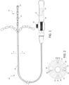
- FIG. 1 schematically depicts a steerable catheter system 10 having a reusable handle 12 and a disposable elongated body 14 that may be attached and detached from the handle.
- the catheter body 14 generally comprises an elongated tubular construction and may have an axial or central lumen.
- the catheter body 14 is flexible, i.e., bendable, but substantially non-compressible along its length.
- the catheter body 14 can be of any suitable construction and made of any suitable material.
- an outer wall may be made of polyurethane or PEBAX.
- the outer wall may also include an imbedded braided mesh of stainless steel or the like to increase torsional stiffness of the catheter body 14 so that when the handle 12 is rotated, a tip section 16 will rotate in a corresponding manner.
- the outer diameter of the catheter body 14 is not critical, and will vary depending on the intended application of the catheter. As a representative example, the diameter may be about 8 french or less.
- the thickness of the outer wall is not critical, but is thin enough so that the catheter body 14 can accommodate deflection members (e.g., puller wires), lead wires, and any other desired wires, cables or tubings while maintaining the desired outer diameter.
- the inner surface of the outer wall may be lined with a stiffening tube to provide improved torsional stability.
- the outer wall may have an outer diameter of from about 0.23 cm (0.090 inch) to about 2.4 cm (0.94 inch) and an inner diameter of from about 0.15 cm (0.061 inch) to about 0.17 cm (0.065 inch).
- the overall length of catheter system 10 may vary depending on the intended application, and may be about 1.2 m (48 inches) in some embodiments.
- Handle 12 and its components may be formed from suitable metals and/or polymeric materials and has an actuator 18 configured as a rotating member, taking the form of a thumb wheel in this embodiment, that actuates one or more deflection members, such as puller wires as described in further detail below.
- the control handle may also include a tension knob 20 that enables the user to adjust the ease by which the actuator 18 can be rotated, or may lock actuator 18 in a desired position.
- Manipulation of actuator 18 may impart a desired degree of deflection in tip section 16, which may be bi-directional as indicated in the figure. In other embodiments, uni-directional or other types of deflection may be employed.
- thumb wheel actuator is depicted in this embodiment, it will be appreciated that any suitable actuator design may be employed as desired, including sliders, pistons, rocker handles or the like. Exemplary details of deflection assemblies and control handles are described in co-pending U.S. application Ser. No. 12/346,834, filed Dec. 30, 2008 , entitled DEFLECTABLE SHEATH INTRODUCER, and commonly-owned U.S. Patent. Nos. 8,137,308, issued March 20, 2012 , entitled CATHETER WITH ADJUSTABLE DEFLECTION SENSITIVITY and 8,348,888, issued Jan. 8, 2013 , entitled STEERING MECHANISM FOR BI-DIRECTIONAL CATHETER, the entire disclosures of each are hereby incorporated by reference.
- catheter system 10 is configured for use in a electrophysiologic (EP) procedure, such as for mapping, pacing and/or ablation in the heart.
- distal tip section 16 may have multiple electrodes, including ring electrodes 22 and tip electrode 24, which may be irrigated if desired as depicted.
- Ring electrodes 22 may range in length from about 1 mm to about 3 mm, and may be spaced apart in any fashion as desired so long as their edges do not touch.
- the electrodes may be used for mapping, pacing, ablation or other operations and may be perforated to deliver irrigation fluid for controlling tissue temperature during the procedure.
- Handle 12 may incorporate a printed circuit board (PCB) 25 (shown in phantom in FIG.
- PCB printed circuit board
- PCB 25 may include a microprocessor for storing or preprocessing data measured by the electrodes to facilitate communication with a patient interface unit or other similar equipment.
- FIG. 2 A cross section of catheter body 14, taken at A-A, is shown in FIG. 2 .
- two off-axis lumens 26 and 28 accommodate puller wires 30, which are slidable within the lumens so that manipulation of actuator 18 may be used to deflect tip section 16.
- Catheter body 14 may have additional lumens as warranted by the intended application.
- lumen 32 may carry lead wires and thermocouple wires 34 for communicating electrical signals to and from ring electrodes 22 and tip electrode 24.
- lumen 36 may carry location sensor cables 38, used in conjunction with a positioning system, such as the CARTO ® 3 System embodying methods as disclosed in U.S. Pat. Nos.
- Each puller wire 30 is made of any suitable metal, such as stainless steel or Nitinol, or other appropriate material, and may have a coating or sleeve 44 of Teflon ® or the like. Each puller wire 30 may have a diameter ranging from about 0.15 mm (0.006 inch) to about 0.025 mm (0.0010 inch). The puller wires 30 may be secured at a desired location in tip section 16, such as by welding to tip electrode 24 or through an anchor embedded in the material of the catheter body.
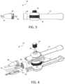
- disposable catheter body 14 may be attached to handle 12 as shown in FIG. 1 and may be detached as shown in FIG. 3 .
- the proximal end of catheter body 14 has a coupling in the form of fitting 46 with external threads that is configured to mate with threaded housing 48 that is rotatably mounted to handle 12 and features complementary internal threads.
- the tapered profile of fitting 46 also provides a strain relief function by creating a more gradual transition between the rigid handle 12 and the more flexible catheter body 14.
- any suitable connection mechanism may be employed, including snaps, latches, bayonet locks, Luer hubs or others.
- Each puller wire 30 is secured to interconnects 50 (only one visible in this view.)
- interconnects 50 For the sake of clarity, the couplings associated with lead and thermocouple wires 34, sensor cables 38 and irrigation tubing 42 are not shown, but any suitable fluidic or electrical connector system may be employed as desired.
- edge connectors provided in fitting 46 and threaded housing may be used to couple electrode lead and thermocouple wires 34 and/or sensor cables 38 with PCB 25,
- any suitable releasable attachment between handle 12 and catheter body 14 may be employed, such as a snap fit connection, a pneumatic push-in connection or the like.
- FIG. 4 Further details of the actuation mechanism of handle 12 are shown in the exploded view of FIG. 4 .
- the complementary halves of fitting 46 define internal supports 52 upon which interconnects 50 travel.
- Sliding member in the form of two racks 54 are deployed within handle 12, longitudinally moving within guides 56 formed by the complementary halves of handle 12 at a distal location and are configured to allow longitudinal movement and restrict off-axis motion of racks 54.
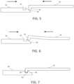
- Cooperating structures are positioned at the proximal ends of interconnects 50 and at the distal ends of racks to allow a releasable engagement. In this embodiment, the ends have a hook-shaped configuration. Interaction of these elements is schematically depicted in FIGs. 5-7 .
- each rack 54 contacts the proximal end of each interconnect as shown in FIG. 5 .
- projection 58 of rack 54 engages ramp 60 of interconnect 50.
- deflecting rack 54 which may be formed of any sufficiently resilient material.
- interconnects 50 are held in position by supports 52 as rack 54 deflects.
- a releasable engagement between rack 54 and interconnect 50 is formed when projection 58 is positioned coextensively over recess 62, allowing rack 54 to return to its nominal configuration, with projection 58 fitting within recess 62 as shown in FIG. 7 .
- a similar releaseable engagement between rack 54 and interconnect 50 may be achieved in other embodiments by reversing the configuration of the cooperating ends.
- Projection 58 and recess 62 may be suitably sized to minimize play between rack 54 and interconnect 50.
- longitudinal motion of rack 54 is transmitted and causes a corresponding longitudinal motion of interconnect 50.
- other means may be used to releasably attach proximal ends of the puller wires with structures driven by one or more actuators, including a hook and loop connection, a snap fit connection or a magnetic connection, so that interconnect 50 and the sliding member rack 54 engage when handle 12 is attached to catheter body 14.
- rack 54 may be transmitted to the deflection member, puller wire 30, in response to manipulation of actuator 18.
- Interconnect 50 and rack 54 disengage when handle 12 is released from catheter body 14.
- only a single puller wire 30, interconnect 50 and rack 54 may be required.
- Other embodiments may include additional components as warranted following these principles to achieve deflection in different directions and/or planes.
- each rack 54 is coupled to actuator 18 by a cylindrical pin 64 that rides within a camming slot 66 formed in actuator 18.
- the pins 64 travel within slots 66, and due to the constraint of guides 56, movement of racks 54 is generally longitudinal.
- racks 54 are attached to interconnects 50 as described above when handle 12 is mated to catheter body 14, the longitudinal movements of racks 54 are translated to longitudinal movement of puller wires 30, as they are secured to interconnects 50.
- Puller wires 30 may be directly attached to interconnects 50, or may be coupled by a transitional material, such as a flexible cord, to reduce kinking of puller wires 30 when being moved.
- slots 66 may be designed to produce motion of the racks 54 with desired characteristics.
- slots 66 may be curved about a radius that displaces racks 54 at the same ratio of rotation to movement no matter what degree actuator 18 has already been turned, such as by having the same ratio throughout the range of travel of actuator 18.
- slots 66 may be configured to cause different ratios of motion at different degrees of rotation.
- the diameter of actuator 18 and length of slots 66 may determine the total amount of movement. In this embodiment, manipulation of actuator 18 causes coordinated movement of the puller wires 30, with one being withdrawn and the other advanced.
- actuator 18 may be coupled to racks 54 by one or more gears.
- tactile feedback may be provided when actuator 18 is in a neutral position corresponding to no deflection of tip section 16, such as by providing a detent at the appropriate position in the range of travel of actuator 18.
- Visual or audible indicators may also be employed.
- racks 54 may be biased by springs or other mechanisms to return to the neutral position. As such, when tension knob 20 is released, tip section 16 may revert to its non-deflected configuration.
- Other embodiments may exploit other mechanisms, such as a push button to allow free movement of racks 54 or otherwise allow them to return to their neutral positions.
- catheter system 10 represents a cost reduction as compared to conventional disposable catheters, in which the handle is discarded along with the catheter body after use. Since handle 12 is removably attached to catheter body 14, it may be reused following appropriate sterilization and cleaning so that only catheter body 14 need be discarded.
- the coupling provided by housing 48 and fitting 46 allows for attachment and release of catheter body 14 from handle 12, while simultaneously aligning racks 54 and interconnects 50 to be releasably engaged to transmit forces from actuator 18 to the deflection mechanisms, such as puller wires 30. Further, this coupling may also be used to form connections between wires, leads, cables and/or tubing that may be carried by catheter body 14. As desired, any or all of these components may either pass through handle 12 or connect directly to fitting 46. Further, the modularity of catheter system 10 allows multiple catheter bodies to be used with the same handle, for example to provide different capabilities or functionalities.
- each tubular shaft may split from a single coupling with the handle.
- each tubular shaft may connect via separate couplings or backshell connections with the handle.
- yet another alternative may involve one or more of the additional catheter bodies connecting to apparatus other than the handle depending on the functionality desired.
- each of the multiple catheter bodies may be employed for different purposes, such as forming an electrical conduit, an independent irrigation lumen or any other suitable function.
- the handle may have interior or exterior channels as appropriate to route the catheter body's tubular shafts to the proximal end of the handle.
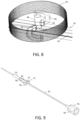
- FIG. 9 schematically depicts a disposable catheter body 14 having similar characteristics to those described above.
- Fitting 70 may have functionality generally equivalent to fitting 46 with regards to facilitating connection to a reusable handle (not shown in this view).
- Fitting 70 may be overmolded onto catheter body 14 or connected though any other suitable means.
- fitting 70 may include frangible support 72 that is configured to retain interconnects 74 in a defined orientation and position with respect to catheter body 14 during attachment of the handle.
- a backshell 76 may be secured to the catheter body 14 by overmolding or other suitable technique to connect with the handle as desired.
- support 72 may have sufficient strength to maintain interconnects 74 in a position to mate with structures equivalent to racks 54, or to be releasably attached through any other suitable interaction, including magnetic, hook and loop, or snap fit as described above, it also may be configured to break upon application of force through an actuator on the handle. As will be appreciated, tailoring the strength of support 72 may be achieved by selecting the appropriate material, such as a polymeric material, by adjusting its thickness or other structural dimension, or both. As desired, a PCB 78 having similar functionality to PCB 25 may be incorporated into the disposable catheter body rather than the handle, such as in backshell 76 as indicated or in any other suitable location. PCB may be used as an alternative to or in conjunction with PCB 25 depending on the embodiment.
Landscapes
- Health & Medical Sciences (AREA)
- Life Sciences & Earth Sciences (AREA)
- Engineering & Computer Science (AREA)
- Heart & Thoracic Surgery (AREA)
- Animal Behavior & Ethology (AREA)
- Veterinary Medicine (AREA)
- Biomedical Technology (AREA)
- Public Health (AREA)
- General Health & Medical Sciences (AREA)
- Surgery (AREA)
- Biophysics (AREA)
- Medical Informatics (AREA)
- Molecular Biology (AREA)
- Physics & Mathematics (AREA)
- Cardiology (AREA)
- Pathology (AREA)
- Nuclear Medicine, Radiotherapy & Molecular Imaging (AREA)
- Radiology & Medical Imaging (AREA)
- Pulmonology (AREA)
- Anesthesiology (AREA)
- Hematology (AREA)
- Vascular Medicine (AREA)
- Mechanical Engineering (AREA)
- Otolaryngology (AREA)
- Optics & Photonics (AREA)
- Plasma & Fusion (AREA)
- Physiology (AREA)
- Human Computer Interaction (AREA)
- Media Introduction/Drainage Providing Device (AREA)
- External Artificial Organs (AREA)
- Infusion, Injection, And Reservoir Apparatuses (AREA)
- Electrotherapy Devices (AREA)
Claims (13)
- Länglicher, rohrförmiger Katheterkörper (14), umfassend ein proximales Ende und einen Spitzenbereich (16) an einem distalen Ende, mindestens ein Lumen (26, 28), das dahindurch verläuft und mindestens ein Ablenkelement (30), das innerhalb des Lumens verschiebbar angeordnet ist, das an einem distalen Ende an dem Spitzenbereich befestigt ist und in einer Verbindung (50) an dem proximalen Ende terminiert; wobei das proximale Ende des Katheterkörpers konfiguriert ist, um an einem Griff (12) lösbar angebracht zu werden, der mindestens ein Gleitelement (54) aufweist, wobei die Verbindung und das Gleitelement in Eingriff stehen, wenn der Griff an dem Katheterkörper angebracht wird, sodass die relative Längsbewegung des Gleitelements auf das Ablenkelement übertragen wird, und wobei die Verbindung und das Gleitelement sich trennen, wenn der Griff von dem Katheterkörper gelöst wird, wobei die Verbindung vor einer Anbringung an dem Griff durch eine zerbrechliche Stütze (72) hinsichtlich des Katheterkörpers stabilisiert wird.
- Katheterkörper nach Anspruch 1, ferner umfassend eine elektronische Schaltung, die in den Katheterkörper derart integriert wird, dass die elektronische Schaltung mit dem Griff in Kommunikation steht, wenn der Griff an dem Katheterkörper angebracht ist.
- Lenkbarer Katheter, umfassend:der längliche, rohrförmige Katheterkörper von Anspruch 1; undder Griff, wobei der Griff konfiguriert ist, um an dem proximalen Ende des Katheterkörpers lösbar angebracht zu werden, der Griff umfassend mindestens einen Aktuator (18), wobei das mindestens eine Gleitelement mit dem Aktuator derart gekoppelt ist, dass eine Manipulation des Aktuators eine relative Längsbewegung hinsichtlich des Griffs bewirkt.
- Lenkbarer Katheter nach Anspruch 3, wobei der Aktuator ein rotierendes Element umfasst, das mit dem Gleitelement durch einen Stift (64) gekoppelt ist, der sich innerhalb eines Nockenschlitzes (66) des rotierenden Elements bewegt.
- Lenkbarer Katheter nach Anspruch 3, wobei der Katheterkörper mindestens zwei Lumen aufweist, die sich dahindurch erstrecken, mit zwei Ablenkelementen, die jeweils innerhalb jeweiliger Lumen verschiebbar angeordnet sind, beide an einem distalen Ende an dem Spitzenbereich befestigt sind und in Zwischenverbindungen an den proximalen Enden terminieren, und wobei der Aktuator mit zwei Gleitelementen gekoppelt ist,
wobei jede Verbindung und jedes Gleitelement in Eingriff stehen, wenn der Griff an dem Katheterkörper angebracht ist, sodass die relative Längsbewegung jedes Gleitelements an jedes in Eingriff stehende Ablenkelement übertragen wird, und wobei jede Verbindung und jedes Gleitelement sich trennen, wenn der Griff von dem Katheterkörper gelöst wird. - Lenkbarer Katheter nach Anspruch 5, wobei der Aktuator ein rotierendes Element umfasst, das mit jedem Gleitelement durch Stifte (64) gekoppelt ist, die sich innerhalb jeweiliger Nockenschlitze (66) des rotierenden Elements bewegen, sodass eine Rotation des Aktuators in eine erste Richtung eine Bewegung eines Gleitelements in eine relativ distale Richtung und die Bewegung des anderen Gleitelements in eine relativ proximale Richtung bewirkt, während die Rotation des Aktuators in eine zweite Richtung die Bewegung des einen Gleitelements in eine relativ proximale Richtung und die Bewegung des anderen Gleitelements in eine relativ distale Richtung bewirkt.
- Lenkbarer Katheter nach Anspruch 4, wobei der Nockenschlitz des Aktuators konfiguriert ist, um einen Radius aufzuweisen, der das Gleitelement über eine Bewegungsreichweite des Aktuators mit einem gleichen Verhältnis von Rotation zu Bewegung verschiebt.
- Lenkbarer Katheter nach Anspruch 3, wobei der Eingriff des Gleitelements und der Verbindung einen Vorsprung (58) umfasst, der innerhalb einer Aussparung (62) passt.
- Lenkbarer Katheter nach Anspruch 8, ferner umfassend eine Rampe (60) auf einem von dem Gleitelement und der Verbindung, um den Vorsprung abzulenken, bis er flächengleich mit der Aussparung positioniert ist.
- Lenkbarer Katheter nach Anspruch 3, wobei sich das Gleitelement innerhalb einer Führung (56) bewegt, die in einem distalen Abschnitt des Griffs ausgebildet ist.
- Lenkbarer Katheter nach Anspruch 3, wobei der Katheterkörper durch ein Gewindegehäuse (48) an dem Griff angebracht ist.
- Lenkbarer Katheter nach Anspruch 3, wobei die zerbrechliche Stütze konfiguriert ist, um nach der Manipulation des Aktuators durch einen Benutzer zu zerbrechen.
- Lenkbarer Katheter nach Anspruch 3, ferner umfassend eine elektronische Schaltung, die in mindestens einem von dem Katheterkörper und dem Griff derart integriert ist, dass die elektronische Schaltung mit Komponenten in dem Katheterkörper in Kommunikation steht, wenn der Griff an dem Katheterkörper angebracht ist.
Applications Claiming Priority (2)
| Application Number | Priority Date | Filing Date | Title |
|---|---|---|---|
| US15/786,414 US10532187B2 (en) | 2017-10-17 | 2017-10-17 | Reusable catheter handle system |
| PCT/US2018/055128 WO2019079082A1 (en) | 2017-10-17 | 2018-10-10 | REUSABLE CATHETER HANDLE SYSTEM |
Publications (3)
| Publication Number | Publication Date |
|---|---|
| EP3697486A1 EP3697486A1 (de) | 2020-08-26 |
| EP3697486B1 true EP3697486B1 (de) | 2024-07-17 |
| EP3697486C0 EP3697486C0 (de) | 2024-07-17 |
Family
ID=64184182
Family Applications (1)
| Application Number | Title | Priority Date | Filing Date |
|---|---|---|---|
| EP18799909.9A Active EP3697486B1 (de) | 2017-10-17 | 2018-10-10 | Wiederverwendbares kathetergriffsystem |
Country Status (6)
| Country | Link |
|---|---|
| US (1) | US10532187B2 (de) |
| EP (1) | EP3697486B1 (de) |
| JP (1) | JP7282759B2 (de) |
| CN (1) | CN111246907B (de) |
| IL (1) | IL273506B2 (de) |
| WO (1) | WO2019079082A1 (de) |
Families Citing this family (23)
| Publication number | Priority date | Publication date | Assignee | Title |
|---|---|---|---|---|
| EP3226743B1 (de) | 2014-12-05 | 2019-08-14 | Fortimedix Surgical B.V. | Verfahren zur herstellung eines lenkbaren instruments sowie solch ein lenkbares instrument |
| EP3668581B1 (de) | 2017-11-28 | 2022-09-21 | St. Jude Medical, Cardiology Division, Inc. | Lumenverwaltungskatheter |
| US12575877B2 (en) | 2018-04-05 | 2026-03-17 | St. Jude Medical, Cardiology Division, Inc. | High density electrode mapping catheter |
| EP4230165A1 (de) | 2018-05-21 | 2023-08-23 | St. Jude Medical, Cardiology Division, Inc. | Hochfrequenzablations- und gleichstromelektroporationskatheter |
| WO2020214027A2 (en) | 2019-04-01 | 2020-10-22 | Fortimedix Assets Ii B.V. | Steerable instrument comprising a hinge with a slotted structure |
| WO2020218921A2 (en) | 2019-04-08 | 2020-10-29 | Fortimedix Assets Ii B.V. | Steerable instrument comprising a detachable part |
| US20230123266A1 (en) * | 2019-06-24 | 2023-04-20 | Medtronic, Inc. | Catheter handle with torque mechanism and valve relief component |
| EP3777946B1 (de) * | 2019-08-15 | 2023-01-18 | Biotronik Ag | Luer-lock-system für digitale ballonkatheter |
| US12544089B1 (en) | 2019-12-24 | 2026-02-10 | Farrow Medtech Llc | Wound-care apparatus and method for cleansing, desloughing, and debriding wounds |
| US11980383B2 (en) * | 2019-12-24 | 2024-05-14 | Farrow Medtech Llc | Wound-care apparatus and method for cleansing, desloughing, and debriding wounds |
| JP7119251B2 (ja) * | 2020-03-17 | 2022-08-16 | 日本ライフライン株式会社 | カテーテル用器具、カテーテル本体およびカテーテル |
| EP4138630A1 (de) | 2020-04-24 | 2023-03-01 | Ambu A/S | Handgriff für ein endoskop |
| WO2021213599A1 (en) | 2020-04-24 | 2021-10-28 | Ambu A/S | An endoscope and a method for assembling an endoscope |
| EP4364680A3 (de) | 2020-08-18 | 2024-07-10 | St. Jude Medical, Cardiology Division, Inc. | Hochdichte elektrodenkatheter mit magnetischer positionsverfolgung |
| US20240024664A1 (en) * | 2020-09-10 | 2024-01-25 | The Board Of Trustees Of The Leland Stanford Junior University | Methods of Treatment and Devices for Repair of Inflammatory, Neurotransmitter, Endocrine or Metabolic Issues |
| WO2022069960A1 (en) * | 2020-09-29 | 2022-04-07 | Baylis Medical Company Inc. | Steerable medical device, handle for a medical device, and method for operating a medical device |
| CN112932654B (zh) * | 2021-01-26 | 2023-06-06 | 四川省人民医院 | 一种消融电极装置 |
| JP2024522032A (ja) | 2021-05-27 | 2024-06-10 | ベクトン・ディキンソン・アンド・カンパニー | カテーテル先端を能動的に再位置決めするためのガイドワイヤを有する静脈内カテーテルデバイス |
| CN118382477A (zh) * | 2021-12-14 | 2024-07-23 | 波士顿科学国际有限公司 | 可转向医疗装置 |
| NL2030160B1 (en) * | 2021-12-16 | 2023-06-28 | Fortimedix Assets Ii B V | Coupling controller for steerable instrument |
| US20230225595A1 (en) * | 2022-01-18 | 2023-07-20 | Neuwave Medical, Inc. | Steerable sheath and adjustable scope attachment |
| US12551658B2 (en) * | 2022-03-25 | 2026-02-17 | St. Jude Medical, Cardiology Division, Inc. | Steerable introducer with slide block divider |
| US20250032752A1 (en) * | 2023-07-28 | 2025-01-30 | Biosense Webster (Israel) Ltd. | Catheter with tactile indication of deflection |
Family Cites Families (46)
| Publication number | Priority date | Publication date | Assignee | Title |
|---|---|---|---|---|
| US5254088A (en) * | 1990-02-02 | 1993-10-19 | Ep Technologies, Inc. | Catheter steering mechanism |
| CA2447239C (en) | 1992-09-23 | 2010-10-19 | Endocardial Therapeutics, Inc. | Endocardial mapping system |
| US5471982A (en) | 1992-09-29 | 1995-12-05 | Ep Technologies, Inc. | Cardiac mapping and ablation systems |
| US5364351A (en) | 1992-11-13 | 1994-11-15 | Ep Technologies, Inc. | Catheter steering mechanism |
| US5441483A (en) * | 1992-11-16 | 1995-08-15 | Avitall; Boaz | Catheter deflection control |
| US5391199A (en) | 1993-07-20 | 1995-02-21 | Biosense, Inc. | Apparatus and method for treating cardiac arrhythmias |
| DE69532139T2 (de) | 1994-08-19 | 2004-08-26 | Biosense Inc. | Medizinisches Diagnose-, Behandlungs- und Darstellungssystem |
| US5718241A (en) | 1995-06-07 | 1998-02-17 | Biosense, Inc. | Apparatus and method for treating cardiac arrhythmias with no discrete target |
| US5769858A (en) | 1995-10-20 | 1998-06-23 | Medtronic, Inc. | Locking stylet for extracting implantable lead or catheter |
| US6007531A (en) | 1995-11-21 | 1999-12-28 | Catheter Imaging Systems, Inc. | Steerable catheter having disposable module and sterilizable handle and method of connecting same |
| US5860953A (en) * | 1995-11-21 | 1999-01-19 | Catheter Imaging Systems, Inc. | Steerable catheter having disposable module and sterilizable handle and method of connecting same |
| DE69738813D1 (de) | 1996-01-08 | 2008-08-14 | Biosense Webster Inc | Mappingkatheter |
| US5826576A (en) * | 1996-08-08 | 1998-10-27 | Medtronic, Inc. | Electrophysiology catheter with multifunction wire and method for making |
| US6221070B1 (en) | 1996-10-18 | 2001-04-24 | Irvine Biomedical, Inc. | Steerable ablation catheter system having disposable shaft |
| US6013052A (en) * | 1997-09-04 | 2000-01-11 | Ep Technologies, Inc. | Catheter and piston-type actuation device for use with same |
| US6123699A (en) * | 1997-09-05 | 2000-09-26 | Cordis Webster, Inc. | Omni-directional steerable catheter |
| US6171277B1 (en) | 1997-12-01 | 2001-01-09 | Cordis Webster, Inc. | Bi-directional control handle for steerable catheter |
| US6200315B1 (en) * | 1997-12-18 | 2001-03-13 | Medtronic, Inc. | Left atrium ablation catheter |
| US6226542B1 (en) | 1998-07-24 | 2001-05-01 | Biosense, Inc. | Three-dimensional reconstruction of intrabody organs |
| US6301496B1 (en) | 1998-07-24 | 2001-10-09 | Biosense, Inc. | Vector mapping of three-dimensionally reconstructed intrabody organs and method of display |
| US20030028182A1 (en) | 1999-04-21 | 2003-02-06 | Cryocath Technologies Inc. | Cryoablation catheter handle |
| US6892091B1 (en) | 2000-02-18 | 2005-05-10 | Biosense, Inc. | Catheter, method and apparatus for generating an electrical map of a chamber of the heart |
| US7027851B2 (en) * | 2002-10-30 | 2006-04-11 | Biosense Webster, Inc. | Multi-tip steerable catheter |
| US7039450B2 (en) * | 2002-11-15 | 2006-05-02 | Biosense Webster, Inc. | Telescoping catheter |
| US8777889B2 (en) * | 2004-06-15 | 2014-07-15 | Ceramatec, Inc. | Apparatus and method for administering a therapeutic agent into tissue |
| ES2552252T3 (es) | 2004-03-23 | 2015-11-26 | Boston Scientific Limited | Sistema de visualización in vivo |
| US7377906B2 (en) | 2004-06-15 | 2008-05-27 | Biosense Webster, Inc. | Steering mechanism for bi-directional catheter |
| US7497853B2 (en) * | 2005-05-05 | 2009-03-03 | Enpath Medical Inc. | Deflectable catheter steering and locking system |
| US20070156114A1 (en) | 2005-12-29 | 2007-07-05 | Worley Seth J | Deflectable catheter with a flexibly attached tip section |
| US8372090B2 (en) | 2006-10-05 | 2013-02-12 | Covidien Lp | Flexible endoscopic stitching devices |
| US8133224B2 (en) | 2006-10-05 | 2012-03-13 | Erbe Elektromedizin Gmbh | Medical instrument |
| US7931616B2 (en) * | 2006-10-31 | 2011-04-26 | Biosense Webster, Inc. | Insert molded catheter puller member connectors and method of making |
| CN201098109Y (zh) * | 2007-08-21 | 2008-08-13 | 复旦大学 | 一种一次性医用内窥镜 |
| US8257386B2 (en) | 2007-09-11 | 2012-09-04 | Cambridge Endoscopic Devices, Inc. | Surgical instrument |
| US8628545B2 (en) | 2008-06-13 | 2014-01-14 | Covidien Lp | Endoscopic stitching devices |
| US8137308B2 (en) | 2008-09-16 | 2012-03-20 | Biosense Webster, Inc. | Catheter with adjustable deflection sensitivity |
| US8808345B2 (en) | 2008-12-31 | 2014-08-19 | Medtronic Ardian Luxembourg S.A.R.L. | Handle assemblies for intravascular treatment devices and associated systems and methods |
| AU2011252740B2 (en) * | 2010-05-11 | 2015-05-28 | Cathrx Ltd | A catheter handle |
| AU2011350085B2 (en) * | 2010-12-27 | 2015-09-03 | Cathrx Ltd | A modular catheter |
| US8777898B2 (en) | 2011-01-31 | 2014-07-15 | Boston Scientific Scimed, Inc. | Medical devices having releasable coupling |
| US9566048B1 (en) | 2011-04-26 | 2017-02-14 | Cardica, Inc. | Surgical instrument with discrete cammed articulation |
| US9162036B2 (en) * | 2011-12-30 | 2015-10-20 | Biosense Webster (Israel), Ltd. | Medical device control handle with multiple puller wires |
| JP6192951B2 (ja) | 2013-03-01 | 2017-09-06 | テルモ株式会社 | 作動部材、および医療器具 |
| US9174024B1 (en) * | 2013-03-15 | 2015-11-03 | St. Jude Medical Luxembourg Holdings S.À.R.L. | Steering control mechanisms for catheters |
| CN105263433B (zh) | 2013-04-22 | 2017-10-31 | 导管治疗有限公司 | 消融导管 |
| DE102013208728A1 (de) | 2013-05-13 | 2014-11-13 | Aesculap Ag | Biegbarer Rohrschaft |
-
2017
- 2017-10-17 US US15/786,414 patent/US10532187B2/en active Active
-
2018
- 2018-10-10 CN CN201880067948.5A patent/CN111246907B/zh active Active
- 2018-10-10 WO PCT/US2018/055128 patent/WO2019079082A1/en not_active Ceased
- 2018-10-10 JP JP2020521576A patent/JP7282759B2/ja active Active
- 2018-10-10 EP EP18799909.9A patent/EP3697486B1/de active Active
-
2020
- 2020-03-23 IL IL273506A patent/IL273506B2/en unknown
Also Published As
| Publication number | Publication date |
|---|---|
| IL273506A (en) | 2020-05-31 |
| US20190111238A1 (en) | 2019-04-18 |
| IL273506B2 (en) | 2023-07-01 |
| WO2019079082A1 (en) | 2019-04-25 |
| US10532187B2 (en) | 2020-01-14 |
| JP2020537573A (ja) | 2020-12-24 |
| IL273506B1 (en) | 2023-03-01 |
| CN111246907A (zh) | 2020-06-05 |
| JP7282759B2 (ja) | 2023-05-29 |
| CN111246907B (zh) | 2022-07-22 |
| EP3697486C0 (de) | 2024-07-17 |
| EP3697486A1 (de) | 2020-08-26 |
Similar Documents
| Publication | Publication Date | Title |
|---|---|---|
| EP3697486B1 (de) | Wiederverwendbares kathetergriffsystem | |
| US12465721B2 (en) | Controllable expandable catheter | |
| US6171277B1 (en) | Bi-directional control handle for steerable catheter | |
| EP0982047B1 (de) | Zweirichtungssteuerbarer Katheter mit Zweirichtungsbedienungshebel | |
| CA2526381C (en) | Articulating mechanism for remote manipulation of a surgical or diagnostic tool | |
| EP0928601B1 (de) | Katheter mit gespülteter Spitze | |
| JP5148920B2 (ja) | 経中隔カテーテル法アッセンブリ及び方法 | |
| EP2752218B1 (de) | Steuergriff mit Spannungsregulierung für unidirektionalen Katheter | |
| US20090247993A1 (en) | Robotic catheter system | |
| EP3064244B1 (de) | Katheter mit unirailseilzugarchitektur | |
| US20180344353A1 (en) | Catheter System for Left Heart Access | |
| WO2016183300A2 (en) | Catheter system for left heart access |
Legal Events
| Date | Code | Title | Description |
|---|---|---|---|
| STAA | Information on the status of an ep patent application or granted ep patent |
Free format text: STATUS: UNKNOWN |
|
| STAA | Information on the status of an ep patent application or granted ep patent |
Free format text: STATUS: THE INTERNATIONAL PUBLICATION HAS BEEN MADE |
|
| PUAI | Public reference made under article 153(3) epc to a published international application that has entered the european phase |
Free format text: ORIGINAL CODE: 0009012 |
|
| STAA | Information on the status of an ep patent application or granted ep patent |
Free format text: STATUS: REQUEST FOR EXAMINATION WAS MADE |
|
| 17P | Request for examination filed |
Effective date: 20200312 |
|
| AK | Designated contracting states |
Kind code of ref document: A1 Designated state(s): AL AT BE BG CH CY CZ DE DK EE ES FI FR GB GR HR HU IE IS IT LI LT LU LV MC MK MT NL NO PL PT RO RS SE SI SK SM TR |
|
| AX | Request for extension of the european patent |
Extension state: BA ME |
|
| DAV | Request for validation of the european patent (deleted) | ||
| DAX | Request for extension of the european patent (deleted) | ||
| RAP3 | Party data changed (applicant data changed or rights of an application transferred) |
Owner name: BIOSENSE WEBSTER (ISRAEL) LTD. |
|
| REG | Reference to a national code |
Ref country code: DE Ref legal event code: R079 Free format text: PREVIOUS MAIN CLASS: A61M0025010000 Ipc: A61B0005010000 Ref document number: 602018071924 Country of ref document: DE |
|
| GRAP | Despatch of communication of intention to grant a patent |
Free format text: ORIGINAL CODE: EPIDOSNIGR1 |
|
| STAA | Information on the status of an ep patent application or granted ep patent |
Free format text: STATUS: GRANT OF PATENT IS INTENDED |
|
| RIC1 | Information provided on ipc code assigned before grant |
Ipc: A61B 17/00 20060101ALI20240206BHEP Ipc: A61B 1/005 20060101ALI20240206BHEP Ipc: A61M 25/01 20060101ALI20240206BHEP Ipc: A61N 1/05 20060101ALI20240206BHEP Ipc: A61B 18/00 20060101ALI20240206BHEP Ipc: A61B 18/14 20060101ALI20240206BHEP Ipc: A61B 5/00 20060101ALI20240206BHEP Ipc: A61B 5/287 20210101ALI20240206BHEP Ipc: A61B 5/06 20060101ALI20240206BHEP Ipc: A61B 5/01 20060101AFI20240206BHEP |
|
| INTG | Intention to grant announced |
Effective date: 20240221 |
|
| GRAS | Grant fee paid |
Free format text: ORIGINAL CODE: EPIDOSNIGR3 |
|
| GRAA | (expected) grant |
Free format text: ORIGINAL CODE: 0009210 |
|
| STAA | Information on the status of an ep patent application or granted ep patent |
Free format text: STATUS: THE PATENT HAS BEEN GRANTED |
|
| AK | Designated contracting states |
Kind code of ref document: B1 Designated state(s): AL AT BE BG CH CY CZ DE DK EE ES FI FR GB GR HR HU IE IS IT LI LT LU LV MC MK MT NL NO PL PT RO RS SE SI SK SM TR |
|
| REG | Reference to a national code |
Ref country code: CH Ref legal event code: EP |
|
| REG | Reference to a national code |
Ref country code: DE Ref legal event code: R096 Ref document number: 602018071924 Country of ref document: DE |
|
| REG | Reference to a national code |
Ref country code: IE Ref legal event code: FG4D |
|
| U01 | Request for unitary effect filed |
Effective date: 20240805 |
|
| U07 | Unitary effect registered |
Designated state(s): AT BE BG DE DK EE FI FR IT LT LU LV MT NL PT RO SE SI Effective date: 20240902 |
|
| U20 | Renewal fee for the european patent with unitary effect paid |
Year of fee payment: 7 Effective date: 20240906 |
|
| PG25 | Lapsed in a contracting state [announced via postgrant information from national office to epo] |
Ref country code: NO Free format text: LAPSE BECAUSE OF FAILURE TO SUBMIT A TRANSLATION OF THE DESCRIPTION OR TO PAY THE FEE WITHIN THE PRESCRIBED TIME-LIMIT Effective date: 20241017 |
|
| PG25 | Lapsed in a contracting state [announced via postgrant information from national office to epo] |
Ref country code: GR Free format text: LAPSE BECAUSE OF FAILURE TO SUBMIT A TRANSLATION OF THE DESCRIPTION OR TO PAY THE FEE WITHIN THE PRESCRIBED TIME-LIMIT Effective date: 20241018 Ref country code: PL Free format text: LAPSE BECAUSE OF FAILURE TO SUBMIT A TRANSLATION OF THE DESCRIPTION OR TO PAY THE FEE WITHIN THE PRESCRIBED TIME-LIMIT Effective date: 20240717 |
|
| PG25 | Lapsed in a contracting state [announced via postgrant information from national office to epo] |
Ref country code: IS Free format text: LAPSE BECAUSE OF FAILURE TO SUBMIT A TRANSLATION OF THE DESCRIPTION OR TO PAY THE FEE WITHIN THE PRESCRIBED TIME-LIMIT Effective date: 20241117 |
|
| PG25 | Lapsed in a contracting state [announced via postgrant information from national office to epo] |
Ref country code: HR Free format text: LAPSE BECAUSE OF FAILURE TO SUBMIT A TRANSLATION OF THE DESCRIPTION OR TO PAY THE FEE WITHIN THE PRESCRIBED TIME-LIMIT Effective date: 20240717 |
|
| PG25 | Lapsed in a contracting state [announced via postgrant information from national office to epo] |
Ref country code: ES Free format text: LAPSE BECAUSE OF FAILURE TO SUBMIT A TRANSLATION OF THE DESCRIPTION OR TO PAY THE FEE WITHIN THE PRESCRIBED TIME-LIMIT Effective date: 20240717 Ref country code: RS Free format text: LAPSE BECAUSE OF FAILURE TO SUBMIT A TRANSLATION OF THE DESCRIPTION OR TO PAY THE FEE WITHIN THE PRESCRIBED TIME-LIMIT Effective date: 20241017 |
|
| PG25 | Lapsed in a contracting state [announced via postgrant information from national office to epo] |
Ref country code: RS Free format text: LAPSE BECAUSE OF FAILURE TO SUBMIT A TRANSLATION OF THE DESCRIPTION OR TO PAY THE FEE WITHIN THE PRESCRIBED TIME-LIMIT Effective date: 20241017 Ref country code: PL Free format text: LAPSE BECAUSE OF FAILURE TO SUBMIT A TRANSLATION OF THE DESCRIPTION OR TO PAY THE FEE WITHIN THE PRESCRIBED TIME-LIMIT Effective date: 20240717 Ref country code: NO Free format text: LAPSE BECAUSE OF FAILURE TO SUBMIT A TRANSLATION OF THE DESCRIPTION OR TO PAY THE FEE WITHIN THE PRESCRIBED TIME-LIMIT Effective date: 20241017 Ref country code: IS Free format text: LAPSE BECAUSE OF FAILURE TO SUBMIT A TRANSLATION OF THE DESCRIPTION OR TO PAY THE FEE WITHIN THE PRESCRIBED TIME-LIMIT Effective date: 20241117 Ref country code: HR Free format text: LAPSE BECAUSE OF FAILURE TO SUBMIT A TRANSLATION OF THE DESCRIPTION OR TO PAY THE FEE WITHIN THE PRESCRIBED TIME-LIMIT Effective date: 20240717 Ref country code: GR Free format text: LAPSE BECAUSE OF FAILURE TO SUBMIT A TRANSLATION OF THE DESCRIPTION OR TO PAY THE FEE WITHIN THE PRESCRIBED TIME-LIMIT Effective date: 20241018 Ref country code: ES Free format text: LAPSE BECAUSE OF FAILURE TO SUBMIT A TRANSLATION OF THE DESCRIPTION OR TO PAY THE FEE WITHIN THE PRESCRIBED TIME-LIMIT Effective date: 20240717 |
|
| PG25 | Lapsed in a contracting state [announced via postgrant information from national office to epo] |
Ref country code: SM Free format text: LAPSE BECAUSE OF FAILURE TO SUBMIT A TRANSLATION OF THE DESCRIPTION OR TO PAY THE FEE WITHIN THE PRESCRIBED TIME-LIMIT Effective date: 20240717 |
|
| PG25 | Lapsed in a contracting state [announced via postgrant information from national office to epo] |
Ref country code: CZ Free format text: LAPSE BECAUSE OF FAILURE TO SUBMIT A TRANSLATION OF THE DESCRIPTION OR TO PAY THE FEE WITHIN THE PRESCRIBED TIME-LIMIT Effective date: 20240717 |
|
| PG25 | Lapsed in a contracting state [announced via postgrant information from national office to epo] |
Ref country code: SK Free format text: LAPSE BECAUSE OF FAILURE TO SUBMIT A TRANSLATION OF THE DESCRIPTION OR TO PAY THE FEE WITHIN THE PRESCRIBED TIME-LIMIT Effective date: 20240717 |
|
| PLBE | No opposition filed within time limit |
Free format text: ORIGINAL CODE: 0009261 |
|
| STAA | Information on the status of an ep patent application or granted ep patent |
Free format text: STATUS: NO OPPOSITION FILED WITHIN TIME LIMIT |
|
| REG | Reference to a national code |
Ref country code: CH Ref legal event code: PL |
|
| 26N | No opposition filed |
Effective date: 20250422 |
|
| PG25 | Lapsed in a contracting state [announced via postgrant information from national office to epo] |
Ref country code: MC Free format text: LAPSE BECAUSE OF FAILURE TO SUBMIT A TRANSLATION OF THE DESCRIPTION OR TO PAY THE FEE WITHIN THE PRESCRIBED TIME-LIMIT Effective date: 20240717 |
|
| PG25 | Lapsed in a contracting state [announced via postgrant information from national office to epo] |
Ref country code: CH Free format text: LAPSE BECAUSE OF NON-PAYMENT OF DUE FEES Effective date: 20241031 |
|
| U20 | Renewal fee for the european patent with unitary effect paid |
Year of fee payment: 8 Effective date: 20250909 |
|
| PGFP | Annual fee paid to national office [announced via postgrant information from national office to epo] |
Ref country code: GB Payment date: 20250828 Year of fee payment: 8 |
|
| PG25 | Lapsed in a contracting state [announced via postgrant information from national office to epo] |
Ref country code: IE Free format text: LAPSE BECAUSE OF NON-PAYMENT OF DUE FEES Effective date: 20241010 |
|
| PG25 | Lapsed in a contracting state [announced via postgrant information from national office to epo] |
Ref country code: CY Free format text: LAPSE BECAUSE OF FAILURE TO SUBMIT A TRANSLATION OF THE DESCRIPTION OR TO PAY THE FEE WITHIN THE PRESCRIBED TIME-LIMIT; INVALID AB INITIO Effective date: 20181010 |
|
| PG25 | Lapsed in a contracting state [announced via postgrant information from national office to epo] |
Ref country code: HU Free format text: LAPSE BECAUSE OF FAILURE TO SUBMIT A TRANSLATION OF THE DESCRIPTION OR TO PAY THE FEE WITHIN THE PRESCRIBED TIME-LIMIT; INVALID AB INITIO Effective date: 20181010 |