EP3697339B1 - Dispositif chirurgical complexe pour la réalisation et protection d'une anastomose - Google Patents
Dispositif chirurgical complexe pour la réalisation et protection d'une anastomose Download PDFInfo
- Publication number
- EP3697339B1 EP3697339B1 EP18804670.0A EP18804670A EP3697339B1 EP 3697339 B1 EP3697339 B1 EP 3697339B1 EP 18804670 A EP18804670 A EP 18804670A EP 3697339 B1 EP3697339 B1 EP 3697339B1
- Authority
- EP
- European Patent Office
- Prior art keywords
- guide tube
- stent
- tube
- anastomosis
- sheath
- Prior art date
- Legal status (The legal status is an assumption and is not a legal conclusion. Google has not performed a legal analysis and makes no representation as to the accuracy of the status listed.)
- Active
Links
Images





Classifications
-
- A—HUMAN NECESSITIES
- A61—MEDICAL OR VETERINARY SCIENCE; HYGIENE
- A61B—DIAGNOSIS; SURGERY; IDENTIFICATION
- A61B17/00—Surgical instruments, devices or methods
- A61B17/068—Surgical staplers, e.g. containing multiple staples or clamps
- A61B17/072—Surgical staplers, e.g. containing multiple staples or clamps for applying a row of staples in a single action, e.g. the staples being applied simultaneously
-
- A—HUMAN NECESSITIES
- A61—MEDICAL OR VETERINARY SCIENCE; HYGIENE
- A61B—DIAGNOSIS; SURGERY; IDENTIFICATION
- A61B17/00—Surgical instruments, devices or methods
- A61B17/11—Surgical instruments, devices or methods for performing anastomosis; Buttons for anastomosis
- A61B17/1114—Surgical instruments, devices or methods for performing anastomosis; Buttons for anastomosis of the digestive tract, e.g. bowels or oesophagus
-
- A—HUMAN NECESSITIES
- A61—MEDICAL OR VETERINARY SCIENCE; HYGIENE
- A61B—DIAGNOSIS; SURGERY; IDENTIFICATION
- A61B17/00—Surgical instruments, devices or methods
- A61B17/11—Surgical instruments, devices or methods for performing anastomosis; Buttons for anastomosis
- A61B17/115—Staplers for performing anastomosis, e.g. in a single operation
- A61B17/1155—Circular staplers comprising a plurality of staples
-
- A—HUMAN NECESSITIES
- A61—MEDICAL OR VETERINARY SCIENCE; HYGIENE
- A61F—FILTERS IMPLANTABLE INTO BLOOD VESSELS; PROSTHESES; DEVICES PROVIDING PATENCY TO, OR PREVENTING COLLAPSING OF, TUBULAR STRUCTURES OF THE BODY, e.g. STENTS; ORTHOPAEDIC, NURSING OR CONTRACEPTIVE DEVICES; FOMENTATION; TREATMENT OR PROTECTION OF EYES OR EARS; BANDAGES, DRESSINGS OR ABSORBENT PADS; FIRST-AID KITS
- A61F2/00—Filters implantable into blood vessels; Prostheses, i.e. artificial substitutes or replacements for parts of the body; Appliances for connecting them with the body; Devices providing patency to, or preventing collapsing of, tubular structures of the body, e.g. stents
- A61F2/02—Prostheses implantable into the body
- A61F2/04—Hollow or tubular parts of organs, e.g. bladders, tracheae, bronchi or bile ducts
-
- A—HUMAN NECESSITIES
- A61—MEDICAL OR VETERINARY SCIENCE; HYGIENE
- A61F—FILTERS IMPLANTABLE INTO BLOOD VESSELS; PROSTHESES; DEVICES PROVIDING PATENCY TO, OR PREVENTING COLLAPSING OF, TUBULAR STRUCTURES OF THE BODY, e.g. STENTS; ORTHOPAEDIC, NURSING OR CONTRACEPTIVE DEVICES; FOMENTATION; TREATMENT OR PROTECTION OF EYES OR EARS; BANDAGES, DRESSINGS OR ABSORBENT PADS; FIRST-AID KITS
- A61F2/00—Filters implantable into blood vessels; Prostheses, i.e. artificial substitutes or replacements for parts of the body; Appliances for connecting them with the body; Devices providing patency to, or preventing collapsing of, tubular structures of the body, e.g. stents
- A61F2/95—Instruments specially adapted for placement or removal of stents or stent-grafts
- A61F2/962—Instruments specially adapted for placement or removal of stents or stent-grafts having an outer sleeve
- A61F2/966—Instruments specially adapted for placement or removal of stents or stent-grafts having an outer sleeve with relative longitudinal movement between outer sleeve and prosthesis, e.g. using a push rod
-
- A—HUMAN NECESSITIES
- A61—MEDICAL OR VETERINARY SCIENCE; HYGIENE
- A61B—DIAGNOSIS; SURGERY; IDENTIFICATION
- A61B17/00—Surgical instruments, devices or methods
- A61B17/068—Surgical staplers, e.g. containing multiple staples or clamps
- A61B17/072—Surgical staplers, e.g. containing multiple staples or clamps for applying a row of staples in a single action, e.g. the staples being applied simultaneously
- A61B2017/07214—Stapler heads
- A61B2017/07278—Stapler heads characterised by its sled or its staple holder
-
- A—HUMAN NECESSITIES
- A61—MEDICAL OR VETERINARY SCIENCE; HYGIENE
- A61B—DIAGNOSIS; SURGERY; IDENTIFICATION
- A61B17/00—Surgical instruments, devices or methods
- A61B17/11—Surgical instruments, devices or methods for performing anastomosis; Buttons for anastomosis
- A61B2017/1132—End-to-end connections
-
- A—HUMAN NECESSITIES
- A61—MEDICAL OR VETERINARY SCIENCE; HYGIENE
- A61B—DIAGNOSIS; SURGERY; IDENTIFICATION
- A61B17/00—Surgical instruments, devices or methods
- A61B17/11—Surgical instruments, devices or methods for performing anastomosis; Buttons for anastomosis
- A61B2017/1142—Purse-string sutures
-
- A—HUMAN NECESSITIES
- A61—MEDICAL OR VETERINARY SCIENCE; HYGIENE
- A61B—DIAGNOSIS; SURGERY; IDENTIFICATION
- A61B2217/00—General characteristics of surgical instruments
- A61B2217/002—Auxiliary appliance
- A61B2217/005—Auxiliary appliance with suction drainage system
-
- A—HUMAN NECESSITIES
- A61—MEDICAL OR VETERINARY SCIENCE; HYGIENE
- A61F—FILTERS IMPLANTABLE INTO BLOOD VESSELS; PROSTHESES; DEVICES PROVIDING PATENCY TO, OR PREVENTING COLLAPSING OF, TUBULAR STRUCTURES OF THE BODY, e.g. STENTS; ORTHOPAEDIC, NURSING OR CONTRACEPTIVE DEVICES; FOMENTATION; TREATMENT OR PROTECTION OF EYES OR EARS; BANDAGES, DRESSINGS OR ABSORBENT PADS; FIRST-AID KITS
- A61F2/00—Filters implantable into blood vessels; Prostheses, i.e. artificial substitutes or replacements for parts of the body; Appliances for connecting them with the body; Devices providing patency to, or preventing collapsing of, tubular structures of the body, e.g. stents
- A61F2/02—Prostheses implantable into the body
- A61F2/04—Hollow or tubular parts of organs, e.g. bladders, tracheae, bronchi or bile ducts
- A61F2002/045—Stomach, intestines
Definitions
- the present invention relates to a complex surgical device useful for performing and protecting an intestinal anastomosis.
- Colorectal anastomoses have a disunity rate of around 20%. Disunion of an anastomosis (fistula) is a serious complication with a mortality of around 20%.
- a connection between the skin and the intestine located upstream of the anastomosis to divert the digestive flow into an external pocket and avoid contact between the anastomosis. and feces.
- the stoma is closed secondly after the anastomosis has healed.
- the presence of a stoma and the need for reoperation to remove it constitute significant constraints for the patient and a significant source of health care costs.
- an anastomosis protection device described in FR 2 941 858 And EP2 395 942 which allows feces to be diverted into the intestinal lumen and avoids stomas.
- This device is composed of a flexible external sheath secured to a stent downstream thereof, said stent being intended to be anchored upstream of the anastomosis.
- the stent is the temporary anchoring element to the walls of the intestine, which holds the sheath in place and the sheath serves to divert the feces towards the anal orifice without contact with the intestinal wall at the level of the anastomosis and thus protect the anastomosis.
- this device has been improved by adding means for controlling the anchoring or release of the stent relative to the intestinal wall.
- the retention in place or the release of the device are reinforced by means of a tube opening into the space of a chamber delimited between an internal sheath and the wall of the stent which makes it possible to create by suction a suction cup effect by attracting the walls of the intestine against the stent to reinforce the anchoring or on the contrary to insufflate air or a fluid to release it.
- the surgical device WO2013/014353 essentially consists of taking advantage of the viscoelasticity of the intestine to attract its internal wall towards the external wall of the stent.
- the intestinal mucosa is flexible and elastic while the walls of the stent are relatively rigid.
- the intestinal wall can be attracted (by suction) and attached to the external walls of the stent under the effect of negative pressure in the stent-mucosa interface.
- the friction force between the intestine and the stent increases rapidly and significantly due to a sort of suction effect. Consequently, the mobility of the stent becomes closely linked to the suction effect, the modulation of which then makes it possible to act on the behavior of the stent in the intestine.
- said injection-suction tube is connected, preferably reversibly at its free longitudinal end to a connection tip, itself reversibly connected or capable of being reversibly connected with an injection device or suction of air or liquid such as a syringe, said connection nozzle comprising a closing device, preferably an anti-reflux valve and a vacuum indicator device capable of indicating the vacuum content in said vacuum chamber , particularly located on a vacuum bulb.
- Said chamber defines a sealed chamber between the waterproof film of the internal sheath and the intestinal wall when said anchoring element is in the position of maximum expansion and immobilized by anchoring against the internal surface of the intestinal wall. And, in the event of separation of said anchoring element and/or in the event of migration of said anchoring element inside the intestine, said chamber loses its tightness. But, we can then suck air through said tube from its free end from outside the patient to attract by suction the intestinal wall against the external surface of said first wall on a part or even on the entire external surface of said first wall delimiting said chamber to stop the migration of the anchoring element by restoring the vacuum in said chamber and therefore the sealing of said chamber.
- Said anchoring element can be maintained in the retracted radial position with an instrument called “introducer” described below, the radial expansion occurring after release of the anchoring element from the introducer.
- the introducer can be in a known manner made up of a semi-rigid guide tube, of the catheter type provided at one of its ends with a handle and whose internal diameter and length make it possible to keep said anchoring element housed there. in its retracted form and said sheath, preferably deployed longitudinally.
- the anastomosis is carried out with a stapler in a known manner with a so-called circular stapler by introducing a piece with a circular cross section called an "anvil” into the intestine upstream of the anastomosis site, at the level of the end. free of the intestine then tightening a wire called “purse wire” around the shaft of the anvil before engaging the body of the stapler in the downstream part of the anastomosis up to the level of the anvil shaft to make the circular stapler cooperate with the anvil for sectioning the tissues and placing the staples.
- a protective device which can be introduced into the intestine even before making the anastomosis, this too in order to facilitate the creation of the anastomosis with the anvil and the stapler, reduce the number of steps during the surgical procedure and reduce operating time.
- the proximal end of said first guide tube or respectively said first connection part comprises reversible fixing means such that said proximal end is able to be fixed reversibly to a said anvil, said flexible sheath being capable of being deployed downstream of said stent by removal of said anvil reversibly fixed to the proximal end of said first guide tube or respectively to said first connecting piece.
- the proximal end of said first guide tube or respectively said first connecting piece comprise means for reversibly fixing to the front front face of said anvil by gluing, screwing, clamping or magnetic connection. It is understood that the removal of said anvil involves the prior separation of said anvil from said proximal end of said first guide tube or respectively from said first connecting piece.
- said introducer comprises at least (i) said first deformable guide tube, (ii) a second rigid guide tube, the proximal end of said first deformable guide tube being fixed or capable of being fixed to the distal end of said second rigid guide tube, (iii) a handle connected to the proximal end of said second rigid guide tube, and (iv) a pusher extending from said handle inside said second rigid guide tube and said first deformable guide tube comprising a pusher rod and a pusher stop at the distal end of the pusher rod.
- said introducer is capable of allowing the implantation of the protection device upstream of the anastomosis site, said pusher stop being capable of pushing said protection device outside the distal end of said first deformable guide tube to allow the radial extension and anchoring of said stent against the wall of the intestine, the proximal end of said pusher rod being able to cooperate with said handle by manually controlling a relative translation of said rod of pusher relative to the first deformable guide tube.
- the introducer is used to introduce the stent before carrying out the anastomosis so that the length of said first deformable guide tube is for example not more than 30 cm only, to place the stent upstream of the anastomosis site.
- the protection device comprises at least one flexible tube called suction tube, preferably two suction tubes, each suction tube being able to extend outside of said stent in downstream of it, in particular after completion of the said anastomosis and removal said anvil and stapler, an open end of said suction tube opening inside the stent into a depression chamber delimited between the internal wall of the stent and an internal film covering the internal wall of the stent preferably said film constituting a extension of said sheath, characterized in that each said suction tube is stored, preferably folded, preferably still wound helically inside said first guide tube, and possibly partly, or even entirely, inside of said stent, the downstream end of each said suction tube being linked to said first guide tube or to a said first connection piece, each said suction tube being capable of being deployed downstream of said stent by removal of said anvil reversibly fixed to the proximal end of said first guide tube or respectively to said first connecting piece.
- the open end of the suction tube preferably consists of an end part of the tube within said chamber perforated by multiple perforations.
- suction tubes make it possible to increase the anchoring force and protects against failure of the first suction tube, for example if the latter becomes blocked.
- the distance between said anchoring position upstream of said anastomosis and said anastomosis is at least equal to 10 cm. More particularly, the distance between the anastomosis and the anchoring site is at most 20 cm.
- the device according to the invention due to its possible implantation before carrying out the anastomosis makes it possible to implement a stent and a sheath of reduced dimensions on the one hand and therefore implanted at a reduced distance in upstream of the anastomosis site compared to what was required in previous achievements such as in WO 2013/014355 , especially at a distance of only 10 to 20cm.
- protection of the anastomosis we mean here protection of the anastomosis during the resumption of intestinal transit.
- downstream and upstream we refer here to the direction of travel from upstream to downstream of intestinal transit and to a position when the devices concerned are in place in the intestine to fulfill their function.
- diswallow end of said sheath, we understand that it is the end intended to deploy in said stent once deployed after removal of the stapler after completion of the anastomosis, even if this swallow end is initially brought closer to the upstream end to be fixed to the internal wall of the first guide tube.
- proximal and distal we refer here to the position in or of the element concerned in relation to the initial introduction site in the patient's body and in practice here also in relation to the handle of the introducer regarding the elements of the introducer.
- the proximal and upstream ends correspond to the downstream and upstream ends respectively for introduction through the anal orifice or a part of intestine downstream of the anastomosis.
- first deformable guide tube of the introducer, we means in practice a semi-flexible tube made of elastomer or PU material thicker than the said sheath and deformable by curvature relative to its longitudinal axis until it can adopt a 90° external curvature.
- This first deformable guide tube has graduations allowing the implantation site to be controlled before release.
- said sheath is fixed in a watertight manner to said anchoring element using watertight fixing means, preferably by fusing joint or an annular joint of elastomeric glue, to each said longitudinal end of said internal sheath, so as to delimit a depression chamber between said internal sheath and said first wall, said temporary anchoring element being coupled to said flexible or semi-rigid tube called suction tube, extending outside said anchoring element, an open end of said suction tube opening into said vacuum chamber.
- downstream end of said sheath and the downstream end of said suction tube(s) are connected to the distal end of said first guide tube, the proximal end (or downstream end) of said first guide tube comprising a second connecting piece fixed or capable of being fixed reversibly to the distal end (or upstream end) of a second rigid guide tube of an introducer device for the introduction of the protection device upstream of the anastomosis site and then capable of being reversibly attached to a said anvil for carrying out the anastomosis.
- the second connection part is fixed or capable of reversibly fixing said first guide tube to the distal end of a second rigid guide tube of an introducer device to secure them for the introduction of the protection device upstream of the site of the anastomosis then separate them for removal of the introducer before implementing the anvil and the stapler.
- said first guide tube comprising a second connecting piece at its proximal end remains introduced into the intestine during the performance of the anastomosis and is removed from the intestine when removing the stapler after the realization of the anastomosis due to its connection with the anvil thus allowing the complete unfolding and deployment of said sheath and said suction tube downstream of said stent due to their connection with said first tube.
- downstream end of said sheath and the downstream end of said suction tube(s) are connected to the distal end (or upstream end ) of said first guide tube by gluing or by a wire.
- the sheath and the suction tube(s) are entirely stored, in particular folded or rolled up, inside the stent except for their downstream parts which come out of the stent at its downstream end to join the upstream end of the first guide tube upstream of the stent, these external parts of the sheath and the suction tube being interposed between the stent and the internal wall of the first guide tube.
- said second connection part is fixed or able to be fixed reversibly by screwing, gluing, clamping or magnetic connection, to an adapter itself able to be fixed reversibly to a so-called stapler anvil, by gluing, clamping or magnetic bonding.
- downstream end of said sheath and preferably the downstream end of said suction tube(s), is (or are) linked to a said first connecting piece of which at least one proximal end is arranged outside the downstream end of said stent.
- the downstream end of said sheath and preferably the downstream end of said suction tube(s) is (or are) linked. to a party distal of said first connecting piece independent of said first guide tube, preferably a tubular distal part stored or capable of being stored inside the downstream end of said stent, and a proximal part of said first connecting piece is arranged outside and at the downstream end of said stent preferably having a flat proximal face of greater diameter than said tubular distal part.
- said first connection piece is placed inside said first guide tube.
- the sheath and the suction tube are entirely stored inside the stent except for their downstream parts which come out of the stent at its downstream end to join the first connection piece pressed against the downstream end of the stent.
- the entire protection device and said first connection part are independent of the first guide tube and the introducer.
- downstream end of said sheath and the downstream end of said suction tube(s) are linked to a said first connection part by gluing or by a wire.
- said first connection part is able to be fixed reversibly to a stop of a pusher rod inside said first guide tube during the introduction of the protection device upstream of the anastomosis site, preferably by bonding, screwing, clamping or magnetic bonding, more preferably by bonding.
- said first connection part is capable of being fixed reversibly directly to a said anvil by gluing, screwing, clamping or magnetic bonding preferably by gluing.
- the introducer device can be completely removed from the intestine after introduction of the protection device upstream of the anastomosis site before carrying out the anastomosis, only said first connecting piece remaining inserted into the anastomosis.
- intestine to be fixed to the anvil with a view to carrying out the anastomosis, said first connecting piece being removed from the intestine when removing the stapler after carrying out the anastomosis due to its connection with the anvil, thus allowing the complete deployment of said sheath and said suction tube(s) downstream of said stent due to their connection with said first connection part.
- the pusher rod is a spiral rod formed of a steel wire wound helically along a virtual longitudinal axis XX' with coaxial contiguous turns of the same diameter, the diameter of the contiguous turns forming a deformable rod capable of being deformed into curvature relative to said longitudinal axis to allow a curvature to be adopted until forming a 90° bend.
- said stent comprises at least one withdrawal loop at one end of its longitudinal ends, preferably two loops at each of its longitudinal ends respectively.
- the suction tube is a semi-rigid tube in particular made of PE or PP and has a length capable of holding in shape and extending inside the intestine from an anal orifice of the patient to said element anchoring, preferably the length of said injection-suction tube being at least 20 cm, more particularly 50 to 150 cm, and the free end of said suction tube outside the patient is connected to a device for suction or injection of gaseous or liquid fluid, in particular air or a cold liquid as explained below.
- the length of the external sheath protects the anastomosis, and protrudes from the anal orifice when said anchoring element is in the anchoring position and it is deployed downstream thereof.
- Said external sheath due to its elastomer constitution, has radial and longitudinal stretchability properties similar to those of the intestinal wall, properties which are those of an elastomeric material in the form of said sheath, the latter having elastic properties radial and longitudinal. These radial and longitudinal elasticity properties of the sheath are similar to those of the colon wall.
- said current part of said first wall extends from the upstream longitudinal end of said first wall to a profiled downstream end part of diameter smaller than that of the cylindrical current part, the external diameter in maximum radial expansion of the downstream end of said first wall being 20 to 40 mm, and the length of said profiled end portion of the first wall being 10 to 30 mm, preferably 15 to 25 mm, preferably the diameter of said end part gradually decreasing between said current part and said downstream end of said first wall.
- said temporary anchoring element is an enteral prosthesis of which said first wall is formed by a mesh of spiral wires, preferably metal wires.
- the radial expansion then results from the crossing of the metal wires whose angular variation makes it possible to vary the width of the diamond or parallelogram of the meshes of said mesh of spiral wires.
- said anchoring element is made of a material which gives it so-called expansion by radial elasticity only at a temperature at least equal to the ambient temperature of 20°C, in particular at the temperature of the human body, said anchoring element being in said retracted radial position at a temperature lower than said ambient temperature, preferably lower than 5°C. It is understood that the tubular-shaped material changes diameter automatically depending on the ambient temperature.
- said anchoring element is an enteral prosthesis of which said first wall is formed by a mesh of spiral wires, preferably made of nitinol.
- Nitinol is a metal alloy exhibiting progressive radial expansion properties as a function of temperature, at temperatures greater than or equal to ambient temperature (25°C), which allows it to be kept in shrink form at colder temperatures, notably at 4°C in storage. Once retracted at low temperature, it remains retracted sufficiently of time to be able to accommodate it in the introducer tube and convey it into the intestine using said introducer. Once released into the intestine, the prosthesis gradually regains its radial expansion under the effect of a higher ambient temperature, that of the human body.
- said sheath is made of biocompatible synthetic material, with a wall thickness of 0.01 to 1 mm, preferably of elastomeric materials of the silicone or polyurethane type of 0.05 to 1 mm thick, and more preferably having radial and longitudinal elasticity properties, and said outer sheath at least having shape memory properties and non-stick properties.
- the thickness characteristics of the outer sheath combined with its elasticity give it a shape memory property.
- shape memory properties we mean here that the elastomeric material constituting said outer sheath naturally returns to its initial shape when it is deformed by folding. Given the great length of the outer sheath, these shape memory properties are important, so that the material naturally regains its longitudinal shape without blocking transit in the event of bending of the outer sheath which can actually occur during its migration after release of the anchoring element.
- the radial expansion then results from the crossing metal wires whose angular variation makes it possible to vary the width of the diamond or parallelogram of the meshes of said mesh of spiral wires.
- a stent is used whose design and shape of the mesh of the spiral wires make it possible to obtain a variation in the diameter of said stent with a minimum variation in length, preferably practically without variation in length at the radial compression.
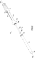
- FIG. 2A represents the introducer device 10 with the first guide tube 12 introduced inside the upstream portion of the intestine 100a.
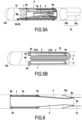
- FIGS. 5A and 5B represent two variants in schematic sectional views (partially exploded for the figure 5A ) of a protection device 5 with the stent compressed at the distal end of the first tube 12 in which the sheath 2 and the suction tube 3 are folded inside the stent, their downstream ends being glued to the distal end of the first tube, the protection device 5 being ready to be expelled by the stop 15b of the pusher 15 outside the first guide tube 12.
- FIG. 6 schematically shows the stent 1 released outside with the first guide tube 12 separated from the rest of the introducer and emptied of the pusher rod after release of the stent and deployment of the sheath 2 and the suction tube 3 downstream of the stent 1 due to the withdrawal of the first guide tube 12 to which they are linked.
- FIGS. 7A to 7C represent different stages of implementation of the anvil at the proximal end of the first guide tube 12 before making the anastomosis.
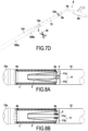
- FIG. 7D represents the removal of the stapler secured to the first tube 12 allowing the deployment of the sheath 2 after completion of the anastomosis.
- FIGS. 8A and 8B represent 2 variants of fixing the suction tube 3 and the sheath 2 on a first connection part 11 downstream of the stent 1 and independent of the first guide tube.
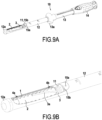
- FIGS. 9A and 9b show a protection device 5 with the stent 1 at the distal end of the first guide tube 12 and the sheath 2 and the suction tube 3 fixed to an adapter 11 itself reversibly fixed to the stop 15b of a pusher 15.
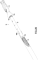
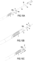
- FIGS. 10A, 10B and 10C represent different stages of removal of the introducer 10 including the first guide tube 12 after release of the stent 1 and partial deployment of the sheath 2 and the suction tube 3 linked to the first connection part 11.
- the Figure 10B shows the approach of the anvil 8 opposite the first connecting piece 11.
- the Figure 10C shows the fixation of the anvil 8 in the upstream intestine 10a before making the anastomosis with the stapler 9.
- FIGS 11A and 11B represent the stapler 9 with the anvil 8 secured to the downstream ends of the sheath 2 and the tube 3 during the production of the anastomosis 101 (fig 11A) and after removal of the stapler and separation from the first part connection 11 after completion of the anastomosis 101 ( Figure 11B ).
- the anastomosis protection device 5 comprises an anchoring element consisting of a stent 1 whose internal wall is covered with a flexible internal sheath 2a delimiting an annular chamber 4 between watertight annular joints 4a-4b between the internal sheath 2a and the wall perforated stent.
- the internal sheath 2a constitutes a waterproof film forming a flexible tubular wall and is extended by a flexible external sheath 2 extending outside of said anchoring element in the longitudinal direction of said stent.
- the entire length of the cylindrical internal surface of the internal wall of the stent is therefore lined with an independent waterproof layer forming an internal sheath 2a, only the longitudinal ends of said internal sheath 2a being fixed in a sealed manner to said anchoring element 1 to using elastomeric annular seals obtained by fusion at each said longitudinal end of said internal sheath.
- the internal sheath 2a is not excessively stretched so as not to stiffen the stent, so that the distance between said internal sheath 2a and the maximum external diameter of the stent is preferably from 0.2 to 10 mm, more preferably from 1 to 5 mm, and the space between said internal sheath 2a and said wall of the stent defines a chamber called depression chamber 4.
- the protection device 5 further comprises a flexible or semi-rigid tube called suction tube 3 extending outside downstream of said stent and opening into the depression chamber 4 between the internal sheath 2a and the wall of the stent 1.
- An upstream part of the suction tube 3 comprising multiple perforations, extends substantially over the entire length of said chamber 4 in the longitudinal direction XX of the device.
- the suction tube 3 opens into said depression chamber by passing through the elastomeric annular seal in a sealed manner at the downstream end of the internal sheath 2a when the tube 3 is introduced through the anal orifice.
- Said suction tube 3 and said outer sheath 2 extend outside of said stent from the same downstream end of said stent.
- the suction tube 3 is used to inject or suck air into the chamber 4 to suck the intestinal wall 100a against the external face of the stent 1, and more generally to modify the anchoring characteristic of the stent 1 relative to the intestinal wall 100a.
- the dimensional data regarding the diameters given above correspond to dimensions suitable for anchoring the device against the mucosa of the internal wall of the intestine 10 at different positions including the rectum.
- the stent is made by a mesh of 0.32mm nitinol wires braided at an angle of 30° and has a diameter of 34mm in the current part and 37mm at its flared ends, a length of 100mm.
- Said sheath 2 extends outside and has a length covering the distance between the anastomosis and the upstream anchoring site, i.e. at least 10 cm.
- Sheath 2 is made of biocompatible, radiopaque synthetic material, in particular TPU 90 AE with 18% BaSO4, its dimensional characteristics are: thickness of 100 ⁇ m, resting length of 400 mm (excluding the internal part of the stent), and external diameter 37mm.
- the fixing of the downstream ends of the outer sheath 2 and the suction tube 3 are different in the two embodiments of Examples 1 and 2, the first guide tube 11 having distinctive implementation characteristics between the two embodiments which will be explained below.
- the stent is retained inside the first guide tube 12 by a device called tulip 12a to form cut-out tabs blocking the passage of the upstream or distal end of the first guide tube 12, which prevents the stent from coming out in the absence of a thrust by the pusher stop described below, the said tongues being elastically deformable under the effect of a said thrust making it possible to expel the stent outside the first guide tube 12.
- the pusher stop 15b is initially positioned just downstream of the stent inside the first deformable guide tube 12.
- FIG. 4A to 4D we show the different stages of carrying out an anastomosis with an anvil 8 and a circular stapler 9.
- An anvil 8 is introduced into the upstream part 100a of the intestine just upstream of the anastomosis site 101 at the level of the free end of the part of the upstream intestine 100a. Then, this free end of the intestine is ligated with a purse string 8' around a shaft 8b behind the cross-section part circular 8a of the anvil 8.
- the outer sheath 2 and the suction tube 3 are unfolded and deployed downstream of the stent by removing the anvil after completion of the stapling.
- Removal of the protective device should ideally be done after healing of the anastomotic area, the standard duration of which is 14 days.
- connection configuration of some of the components of the introducer with each other or with the protection device 1 are different and in particular the downstream longitudinal ends of the external sheath 3 and the tube d
- the aspiration-injection 4 are linked to an element of the introducer device which is different.
- the downstream ends of the external sheath 2 and of the suction tube 3 are fixed to the distal end of said first guide tube 12 in the embodiment of Example 1 and to a first connection part 11 capable of being fixed reversibly to the stop 15b of the pusher in the embodiment of Example 2.
- FIG. 5A, 5B, 6 And 7A-7B there is shown a first embodiment of a complex device according to the invention in which the downstream ends of the sheath 2 and the suction tube 3 are fixed at 2b-3b near the upstream or proximal end of the first deformable tube 12.
- the sheath 2 and the suction tube 3 are folded inside the stent 1 and emerge downstream of the stent beyond the joint 4b to join from the outside, the upstream end of the first guide tube 12, the ends of the sheath 2 and the suction tube 3 being stuck against the internal wall of the first guide tube 12 in 2b-3b near the upstream or proximal end of the first guide tube 12.
- FIG. 5B we have schematically represented an embodiment in which there are several folds of the sheath 2 and the suction tube 3 inside the stent 1 which sheath 2 and suction tube 3 join the internal wall of the first tube deformable 12 by being interposed between the external wall of the stent 1 and the internal wall of the first guide tube 12.
- FIG. 5B we have schematically illustrated the positioning of the stent 1 inside the first tube guide 12 by excessively exaggerating the space between the stent 1 and the internal wall of the first guide tube 12 to show the positioning of the sheath 2 and suction tube 3 outside the stent 1.
- the stent 1 is in radial compression exerting a thrust against the internal wall of the first guide tube 12 with the sheath 2 interposed and stuck between them at this initial stage.
- the second connection part 12b is located substantially at the level of the free end of the upstream part 100a of the intestine and is therefore in position to receive the anvil 8 via the intercalation of an adapter 7 as shown on the Figures 7A to 7C .
- the anastomosis is carried out with the stapler 9 as described with reference to the Figures 4A to 4C .
- the stapler is shown downstream of a downstream segment of intestine 100b schematically, it being understood that the stapler 9 is in fact removed from the intestine via the rectum.
Landscapes
- Health & Medical Sciences (AREA)
- Life Sciences & Earth Sciences (AREA)
- Engineering & Computer Science (AREA)
- Biomedical Technology (AREA)
- Surgery (AREA)
- Animal Behavior & Ethology (AREA)
- Veterinary Medicine (AREA)
- Heart & Thoracic Surgery (AREA)
- General Health & Medical Sciences (AREA)
- Public Health (AREA)
- Medical Informatics (AREA)
- Molecular Biology (AREA)
- Nuclear Medicine, Radiotherapy & Molecular Imaging (AREA)
- Cardiology (AREA)
- Physiology (AREA)
- Oral & Maxillofacial Surgery (AREA)
- Transplantation (AREA)
- Vascular Medicine (AREA)
- Gastroenterology & Hepatology (AREA)
- Pulmonology (AREA)
- Surgical Instruments (AREA)
- Prostheses (AREA)
- Materials For Medical Uses (AREA)
Applications Claiming Priority (2)
| Application Number | Priority Date | Filing Date | Title |
|---|---|---|---|
| FR1759847A FR3072557B1 (fr) | 2017-10-19 | 2017-10-19 | Dispositif chirurgical complexe pour la realisation et protection d'une anastomose. |
| PCT/FR2018/052388 WO2019077218A1 (fr) | 2017-10-19 | 2018-09-28 | Dispositif chirurgical complexe pour la réalisation et protection d'une anastomose |
Publications (3)
| Publication Number | Publication Date |
|---|---|
| EP3697339A1 EP3697339A1 (fr) | 2020-08-26 |
| EP3697339C0 EP3697339C0 (fr) | 2024-07-10 |
| EP3697339B1 true EP3697339B1 (fr) | 2024-07-10 |
Family
ID=60765873
Family Applications (1)
| Application Number | Title | Priority Date | Filing Date |
|---|---|---|---|
| EP18804670.0A Active EP3697339B1 (fr) | 2017-10-19 | 2018-09-28 | Dispositif chirurgical complexe pour la réalisation et protection d'une anastomose |
Country Status (7)
| Country | Link |
|---|---|
| US (5) | US11589869B2 (https=) |
| EP (1) | EP3697339B1 (https=) |
| JP (2) | JP7424971B2 (https=) |
| CN (2) | CN111225631B (https=) |
| ES (1) | ES2986560T3 (https=) |
| FR (1) | FR3072557B1 (https=) |
| WO (1) | WO2019077218A1 (https=) |
Families Citing this family (20)
| Publication number | Priority date | Publication date | Assignee | Title |
|---|---|---|---|---|
| ES2898345T3 (es) | 2009-07-15 | 2022-03-07 | Gt Metabolic Solutions Inc | Dispositivos para un baipás gástrico sin incisión |
| BR112012016666A2 (pt) | 2010-01-05 | 2018-06-05 | Beacon Endoscopic Corp | métodos e aparelhos para anastomose de compressão induzida por imã entre órgãos adjacentes. |
| US8870898B2 (en) | 2010-01-05 | 2014-10-28 | GI Windows, Inc. | Self-assembling magnetic anastomosis device having an exoskeleton |
| FR2978345B1 (fr) | 2011-07-25 | 2013-08-30 | Charam Khosrovaninejad | Dispositif chirurgical d'ancrage controle dans l'intestin. |
| MX2017011638A (es) | 2015-03-12 | 2018-11-09 | Gi Windows Inc | Dispositivos magnéticos de anastomosis con fuerza magnética variada a una distancia. |
| FR3072557B1 (fr) * | 2017-10-19 | 2019-11-08 | Safeheal | Dispositif chirurgical complexe pour la realisation et protection d'une anastomose. |
| JP7374129B2 (ja) | 2018-06-02 | 2023-11-06 | ジーアイ ウィンドウズ, インコーポレイテッド | 吻合部を形成するためのシステム、装置および方法 |
| FR3097421A1 (fr) | 2019-06-24 | 2020-12-25 | Safeheal | Dispositif pour le lavement d’une anastomose intestinale in situ |
| CA3192930A1 (en) | 2020-09-18 | 2022-03-24 | Michel Gagner | Anastomosis formation with magnetic devices having temporary retention member |
| US11534171B2 (en) | 2020-12-18 | 2022-12-27 | Gt Metabolic Solutions, Inc. | Devices and methods for assisting magnetic compression anastomosis |
| CA3205950A1 (en) * | 2020-12-28 | 2022-07-07 | Convatec Technologies Inc. | Non-collapsible catheter tube |
| JP2024516146A (ja) | 2021-04-20 | 2024-04-12 | ジーアイ ウィンドウズ, インコーポレイテッド | 内視鏡または腹腔鏡磁気ナビゲーション用のシステム、装置および方法 |
| EP4329638A4 (en) | 2021-04-30 | 2025-02-26 | GT Metabolic Solutions, Inc. | Anastomosis formation with magnetic devices having bioresorbable retention member |
| WO2022245458A1 (en) | 2021-05-20 | 2022-11-24 | G.I. Windows, Inc. | Systems, devices, and methods for forming anastomoses |
| USD1081998S1 (en) | 2022-03-17 | 2025-07-01 | Gt Metabolic Solutions, Inc. | Anastomosis formation device |
| US12201300B2 (en) | 2022-08-05 | 2025-01-21 | G.I. Windows, Inc. | Magnetic compression anastomosis device with multipiece vertebra |
| WO2024050095A1 (en) | 2022-09-01 | 2024-03-07 | G.I. Windows, Inc. | Pressure profile magnetic compression anastomosis devices |
| EP4580514A1 (en) | 2022-09-02 | 2025-07-09 | G.I. Windows, Inc. | Systems, devices, and methods for endoscope or laparoscope magnetic navigation |
| WO2024194771A2 (en) | 2023-03-17 | 2024-09-26 | SafeHeal SAS | Systems and methods for introducing and monitoring a negative pressure device for protecting an intestinal anastomosis |
| CN119366990B (zh) * | 2024-12-06 | 2026-03-06 | 江苏博朗森思医疗器械有限公司 | 防瘘管型吻合器 |
Citations (1)
| Publication number | Priority date | Publication date | Assignee | Title |
|---|---|---|---|---|
| FR2846868B1 (fr) * | 2002-11-08 | 2005-12-02 | Charam Khosrovaninejad | Agrafeuse pour la suture d'organes creux, enclume et arbre d'enclume pour une telle agrafeuse, outil et kit pour realiser de telles sutures |
Family Cites Families (163)
| Publication number | Priority date | Publication date | Assignee | Title |
|---|---|---|---|---|
| US3799172A (en) | 1972-09-25 | 1974-03-26 | R Szpur | Retention catheter |
| US3885567A (en) | 1973-02-20 | 1975-05-27 | John R Ross | Gastrointestinal aspirator pump |
| US4905693A (en) * | 1983-10-03 | 1990-03-06 | Biagio Ravo | Surgical method for using an intraintestinal bypass graft |
| US4627837A (en) | 1984-05-30 | 1986-12-09 | German Gonzalo | Catheter device |
| US4721109A (en) | 1986-04-08 | 1988-01-26 | Healey Maureen A | Temporary anastomotic device |
| US4716900A (en) * | 1986-05-09 | 1988-01-05 | Pfizer Hospital Products Group, Inc. | Intraintestinal bypass graft |
| US5425739A (en) | 1989-03-09 | 1995-06-20 | Avatar Design And Development, Inc. | Anastomosis stent and stent selection system |
| CA2074304C (en) | 1991-08-02 | 1996-11-26 | Cyril J. Schweich, Jr. | Drug delivery catheter |
| US5662713A (en) | 1991-10-09 | 1997-09-02 | Boston Scientific Corporation | Medical stents for body lumens exhibiting peristaltic motion |
| AU678350B2 (en) | 1992-05-08 | 1997-05-29 | Schneider (Usa) Inc. | Esophageal stent and delivery tool |
| AU692167B2 (en) | 1993-09-21 | 1998-06-04 | Sekisui Kagaku Kogyo Kabushiki Kaisha | Plastic foam material composed of polyolefin based resin and silane-modified polymer and method for making same |
| US5534007A (en) | 1995-05-18 | 1996-07-09 | Scimed Life Systems, Inc. | Stent deployment catheter with collapsible sheath |
| US5785679A (en) | 1995-07-19 | 1998-07-28 | Endotex Interventional Systems, Inc. | Methods and apparatus for treating aneurysms and arterio-venous fistulas |
| US6254642B1 (en) | 1997-12-09 | 2001-07-03 | Thomas V. Taylor | Perorally insertable gastroesophageal anti-reflux valve prosthesis and tool for implantation thereof |
| US6325798B1 (en) | 1998-02-19 | 2001-12-04 | Curon Medical, Inc. | Vacuum-assisted systems and methods for treating sphincters and adjoining tissue regions |
| DE69935716T2 (de) | 1998-05-05 | 2007-08-16 | Boston Scientific Ltd., St. Michael | Stent mit glatten enden |
| US7267794B2 (en) | 1998-09-04 | 2007-09-11 | Amick Darryl D | Ductile medium-and high-density, non-toxic shot and other articles and method for producing the same |
| US6398758B1 (en) | 1999-02-16 | 2002-06-04 | Stephen C. Jacobsen | Medicament delivery system |
| US6319275B1 (en) | 1999-04-07 | 2001-11-20 | Medtronic Ave, Inc. | Endolumenal prosthesis delivery assembly and method of use |
| US6103255A (en) | 1999-04-16 | 2000-08-15 | Rutgers, The State University | Porous polymer scaffolds for tissue engineering |
| US6068636A (en) | 1999-04-23 | 2000-05-30 | Chen; Te-Chuan | Intra-intestinal bypass gun |
| US6926724B1 (en) | 1999-05-04 | 2005-08-09 | City Of Hope | Visceral anastomotic device and method of using same |
| JP2000316979A (ja) | 1999-05-10 | 2000-11-21 | Fuji Systems Kk | ステント |
| JP4542297B2 (ja) | 1999-10-04 | 2010-09-08 | 寛治 井上 | 移植用器具の折り畳み方法、及び、移植用器具 |
| US6824533B2 (en) | 2000-11-29 | 2004-11-30 | Hill-Rom Services, Inc. | Wound treatment apparatus |
| US6679264B1 (en) | 2000-03-04 | 2004-01-20 | Emphasys Medical, Inc. | Methods and devices for use in performing pulmonary procedures |
| US6585926B1 (en) | 2000-08-31 | 2003-07-01 | Advanced Cardiovascular Systems, Inc. | Method of manufacturing a porous balloon |
| US7643887B2 (en) | 2001-05-01 | 2010-01-05 | Intrapace, Inc. | Abdominally implanted stimulator and method |
| US8182527B2 (en) | 2001-05-07 | 2012-05-22 | Cordis Corporation | Heparin barrier coating for controlled drug release |
| MXPA04008789A (es) | 2002-03-11 | 2004-11-26 | Becton Dickinson Co | Sistema y metodo para la fabricacion de cuchillas quirurgicas. |
| CA2461658C (en) | 2002-04-09 | 2007-03-13 | Jae-Hwang Kim | Indwelling fecal diverting device |
| JP2005524485A (ja) | 2002-05-09 | 2005-08-18 | ディー.イーガン トマス | 胃部のバイパスプロテーゼ法 |
| US6808492B2 (en) | 2002-08-16 | 2004-10-26 | Linvatec Corporation | Endoscopic cannula fixation system |
| US7147627B2 (en) | 2002-08-21 | 2006-12-12 | Hollister Incorporated | Bowel management system |
| EP1405612A1 (en) | 2002-10-02 | 2004-04-07 | Sapi Med S.p.A. | Transanal device |
| EP1415671A1 (en) | 2002-11-01 | 2004-05-06 | Polyganics B.V. | Biodegradable drains for medical applications |
| DE60232380D1 (https=) | 2002-11-07 | 2009-06-25 | Rolf Weidenhagen | |
| ITMO20020337A1 (it) | 2002-11-21 | 2004-05-22 | G A M A H S Srl | Dispositivo per anastomosi. |
| US7766973B2 (en) | 2005-01-19 | 2010-08-03 | Gi Dynamics, Inc. | Eversion resistant sleeves |
| US20070032879A1 (en) * | 2002-12-02 | 2007-02-08 | Levine Andy H | Anti-buckling sleeve |
| US7025791B2 (en) | 2002-12-02 | 2006-04-11 | Gi Dynamics, Inc. | Bariatric sleeve |
| US7608114B2 (en) | 2002-12-02 | 2009-10-27 | Gi Dynamics, Inc. | Bariatric sleeve |
| US7141071B2 (en) | 2002-12-23 | 2006-11-28 | Python Medical, Inc. | Implantable digestive tract organ |
| US7803574B2 (en) | 2003-05-05 | 2010-09-28 | Nanosys, Inc. | Medical device applications of nanostructured surfaces |
| DE10327231B3 (de) | 2003-06-13 | 2005-02-17 | Universitätsklinikum Freiburg | Saugstent |
| US20070198078A1 (en) | 2003-09-03 | 2007-08-23 | Bolton Medical, Inc. | Delivery system and method for self-centering a Proximal end of a stent graft |
| US6943690B2 (en) | 2003-09-04 | 2005-09-13 | Ecolab Inc. | Flow verification mechanism |
| US8021331B2 (en) | 2003-09-15 | 2011-09-20 | Atrium Medical Corporation | Method of coating a folded medical device |
| US7547312B2 (en) | 2003-09-17 | 2009-06-16 | Gore Enterprise Holdings, Inc. | Circular stapler buttress |
| EP1708655A1 (en) | 2003-12-09 | 2006-10-11 | GI Dynamics, Inc. | Apparatus to be anchored within the gastrointestinal tract and anchoring method |
| US8252009B2 (en) | 2004-03-09 | 2012-08-28 | Ethicon Endo-Surgery, Inc. | Devices and methods for placement of partitions within a hollow body organ |
| US8181840B2 (en) | 2004-03-19 | 2012-05-22 | Tyco Healthcare Group Lp | Tissue tensioner assembly and approximation mechanism for surgical stapling device |
| EP1588667A1 (en) | 2004-04-20 | 2005-10-26 | Polyganics B.V. | Devices for anastomosis |
| US20050255230A1 (en) | 2004-05-17 | 2005-11-17 | Clerc Claude O | Method of manufacturing a covered stent |
| US20050273075A1 (en) | 2004-06-08 | 2005-12-08 | Peter Krulevitch | Method for delivering drugs to the adventitia using device having microprojections |
| EP1799145B1 (en) | 2004-09-17 | 2016-12-21 | GI Dynamics, Inc. | Gastrointestinal anchor |
| US7938307B2 (en) | 2004-10-18 | 2011-05-10 | Tyco Healthcare Group Lp | Support structures and methods of using the same |
| WO2006053291A2 (en) | 2004-11-09 | 2006-05-18 | Proxy Biomedical Limited | Tissue scaffold |
| US7744914B2 (en) | 2005-04-11 | 2010-06-29 | Regents Of The University Of California | Vascular implant device |
| US20080161717A1 (en) | 2005-05-10 | 2008-07-03 | Michael Eric Gertner | Obesity Treatment Systems |
| US20070051375A1 (en) | 2005-09-06 | 2007-03-08 | Milliman Keith L | Instrument introducer |
| US7509175B2 (en) | 2006-08-03 | 2009-03-24 | Intrapace, Inc. | Method and devices for stimulation of an organ with the use of a transectionally placed guide wire |
| US20090018606A1 (en) | 2005-10-12 | 2009-01-15 | Intrapace, Inc. | Methods and Devices for Stimulation of an Organ with the Use of a Transectionally Placed Guide Wire |
| US20070088373A1 (en) | 2005-10-18 | 2007-04-19 | Endogastric Solutions, Inc. | Invaginator for gastroesophageal flap valve restoration device |
| DE102005050386A1 (de) | 2005-10-20 | 2007-04-26 | Campus Gmbh & Co. Kg | Temporär in einem Körperhohlgefäß ablegbarer Stent |
| US20070179590A1 (en) | 2005-12-29 | 2007-08-02 | Wenfeng Lu | Hybrid intraluminal device with varying expansion force |
| US7845537B2 (en) | 2006-01-31 | 2010-12-07 | Ethicon Endo-Surgery, Inc. | Surgical instrument having recording capabilities |
| US8376981B2 (en) | 2006-03-02 | 2013-02-19 | Michael D. Laufer | Gastrointestinal implant and methods for use |
| US20070262161A1 (en) | 2006-05-10 | 2007-11-15 | Philip Davies | Power Saving Apparatus and Method Thereof |
| US7922684B2 (en) | 2006-05-30 | 2011-04-12 | Boston Scientific Scimed, Inc. | Anti-obesity dual stent |
| US20080004566A1 (en) | 2006-06-30 | 2008-01-03 | Dale Sloan | Gastrointestinal insufflation device and method |
| US20080039878A1 (en) | 2006-07-06 | 2008-02-14 | Williams Michael S | Systems and methods for restoring function of diseased bowel |
| JP2008035909A (ja) | 2006-08-01 | 2008-02-21 | Olympus Medical Systems Corp | 内視鏡用挿入補助具 |
| EP2061397B1 (en) * | 2006-09-02 | 2015-01-07 | Barosense, Inc. | Intestinal sleeves and associated deployment systems |
| WO2008039800A2 (en) | 2006-09-25 | 2008-04-03 | Valentx, Inc. | Toposcopic access and delivery devices |
| MX2009003284A (es) | 2006-09-26 | 2010-02-09 | Boehringer Technologies Lp | Sistema de bomba de presion negativa para terapia de heridas. |
| AU2007314438A1 (en) | 2006-10-26 | 2008-05-08 | Hourglass Technologies, Inc. | Methods and devices for treating obesity and GERD by intussuscepting a portion of stomach tissue |
| US20110257723A1 (en) | 2006-11-07 | 2011-10-20 | Dc Devices, Inc. | Devices and methods for coronary sinus pressure relief |
| US20140163664A1 (en) | 2006-11-21 | 2014-06-12 | David S. Goldsmith | Integrated system for the ballistic and nonballistic infixion and retrieval of implants with or without drug targeting |
| US8801647B2 (en) | 2007-02-22 | 2014-08-12 | Gi Dynamics, Inc. | Use of a gastrointestinal sleeve to treat bariatric surgery fistulas and leaks |
| US20080208325A1 (en) | 2007-02-27 | 2008-08-28 | Boston Scientific Scimed, Inc. | Medical articles for long term implantation |
| US8114045B2 (en) | 2007-03-02 | 2012-02-14 | Cook Medical Technologies Llc | Apparatus and methods for delaying gastric emptying to treat obesity |
| EP2134303A1 (en) | 2007-03-29 | 2009-12-23 | Jaime Vargas | Intragastric implant devices |
| WO2008124638A1 (en) | 2007-04-06 | 2008-10-16 | Dr, Kelley Cancer Foundation | Methods and apparatus for surgical anastomosis |
| WO2008125145A1 (en) | 2007-04-13 | 2008-10-23 | Synergio Ag | A tissue penetration device and method |
| US8167859B2 (en) | 2007-04-23 | 2012-05-01 | Polyzen Inc. | Ostomy bag mounting structure |
| WO2008157362A2 (en) | 2007-06-13 | 2008-12-24 | Boston Scientific Scimed, Inc. | Anti-migration features and geometry for a shape memory polymer stent |
| JP5623907B2 (ja) | 2007-09-05 | 2014-11-12 | アルコン レンゼックス, インコーポレーテッド | レーザ手術におけるレーザ誘起保護シールド |
| US8221783B2 (en) | 2007-09-10 | 2012-07-17 | Boston Scientific Scimed, Inc. | Medical devices with triggerable bioadhesive material |
| US20090069904A1 (en) | 2007-09-12 | 2009-03-12 | Applied Medical Research | Biomaterial including micropores |
| US8529497B2 (en) | 2007-12-04 | 2013-09-10 | Jae-Hwang Kim | Apparatus and method for controlling fecal diverting device |
| EP2240215B1 (en) | 2008-01-17 | 2014-01-08 | Boston Scientific Scimed, Inc. | Stent with anti-migration feature |
| US10350050B2 (en) | 2008-05-01 | 2019-07-16 | Ethicon Endo-Surgery, Inc. | Method for gastric volume reduction surgery |
| CN102076526A (zh) | 2008-07-01 | 2011-05-25 | 沃尔沃拉斯特瓦格纳公司 | 车辆用显示器保持架 |
| US20100010519A1 (en) | 2008-07-09 | 2010-01-14 | Joshua Stopek | Anastomosis Sheath And Method Of Use |
| US8491612B2 (en) | 2008-07-09 | 2013-07-23 | Covidien Lp | Anastomosis sheath and method of use |
| US20100076470A1 (en) | 2008-09-22 | 2010-03-25 | Tyco Healthcare Group Lp | Methods and Devices for Sheath Compression |
| US20100010518A1 (en) | 2008-07-09 | 2010-01-14 | Joshua Stopek | Anastomosis Sheath And Method Of Use |
| CA2730760A1 (en) | 2008-07-16 | 2010-01-21 | Surmodics Pharmaceuticals, Inc. | Process for preparing microparticles containing bioactive peptides |
| EP2320980A4 (en) | 2008-08-13 | 2016-03-23 | Binerix Medical Ltd | LINING FOR TUBULAR BODY PART AND APPARATUS AND METHODS OF INSTALLING THE SAME |
| EP2346414A2 (en) | 2008-09-20 | 2011-07-27 | Steven Craig Anderson | Apparatus and method for tissue adhesion |
| FR2941858B1 (fr) * | 2009-02-10 | 2011-03-11 | Charam Khosrvaninejad | Dispositif chirurgical apte a realiser la protection temporaire d'une anastomose |
| CA2756991A1 (en) | 2009-04-03 | 2010-10-07 | Metamodix, Inc. | Modular gastrointestinal prostheses |
| US8702641B2 (en) | 2009-04-03 | 2014-04-22 | Metamodix, Inc. | Gastrointestinal prostheses having partial bypass configurations |
| WO2011006098A2 (en) | 2009-07-10 | 2011-01-13 | Metamodix, Inc. | External anchoring configurations for modular gastrointestinal prostheses |
| US9173734B2 (en) | 2009-09-29 | 2015-11-03 | IBIS Medical, Inc. | Intragastric implant devices |
| KR101109706B1 (ko) | 2009-10-01 | 2012-01-31 | 신경민 | 비만 환자 치료용 벌룬스텐트 |
| US20110190905A1 (en) | 2009-12-18 | 2011-08-04 | Vysera Biomedical Limited | Gastrointestinal implant |
| AU2011203951B2 (en) | 2010-01-07 | 2015-09-03 | Metamodix, Inc. | Gastrointestinal prostheses having partial bypass configurations |
| PT2359891E (pt) | 2010-02-16 | 2013-04-02 | Miracor Medical Systems Gmbh | Dispositivo de controlo e inflação para um cateter de balão |
| EP2552350A1 (en) | 2010-03-26 | 2013-02-06 | Ibis Medical Inc. | Intragastric implant devices |
| US8753407B2 (en) | 2010-06-04 | 2014-06-17 | Endoshield, Inc. | Temporary protective gastrointestinal device |
| US8709093B2 (en) | 2010-08-09 | 2014-04-29 | Boston Scientific Scimed, Inc. | Tracheal stent with longitudinal ribs to minimize stent movement, coughing and halitosis |
| WO2012039291A1 (ja) | 2010-09-22 | 2012-03-29 | テルモ株式会社 | 生体接着シートおよびシート接着用デバイス |
| JP6241877B2 (ja) | 2010-12-01 | 2017-12-06 | ダニエル・エデュアード・クライナー | 管腔内減圧療法に使用される器具 |
| JP6153133B2 (ja) | 2010-12-15 | 2017-06-28 | コロスパン リミテッドColospan Ltd. | 吻合部位をバイパスするためのシステムおよび方法 |
| CA2833232C (en) | 2011-04-15 | 2018-05-22 | University Of Massachusetts | Surgical cavity drainage and closure system |
| FR2978345B1 (fr) * | 2011-07-25 | 2013-08-30 | Charam Khosrovaninejad | Dispositif chirurgical d'ancrage controle dans l'intestin. |
| FR2978432B1 (fr) | 2011-07-26 | 2014-12-05 | Air Liquide | Raccord de remplissage, recipient, procede de remplissage et prise de conditionnement |
| WO2013026474A1 (en) | 2011-08-23 | 2013-02-28 | Ethicon Endo-Surgery, Inc. | Devices and methods for anchoring an endoluminal sleeve in the gi tract |
| DE102011082347A1 (de) | 2011-09-08 | 2013-03-14 | Paul Hartmann Ag | Wundauflage zur Verwendung bei der Unterdruckbehandlung von Wunden |
| US8636810B2 (en) | 2011-09-28 | 2014-01-28 | Ethicon, Inc. | Negative pressure intestinal anastomosis protection devices |
| US20130087579A1 (en) | 2011-10-11 | 2013-04-11 | Shanina C. Knighton | Sanitation dispenser |
| TWI467920B (zh) | 2011-10-31 | 2015-01-01 | Richtek Technology Corp | 高壓偏移偵測電路 |
| US10162932B2 (en) | 2011-11-10 | 2018-12-25 | Siemens Healthcare Gmbh | Method and system for multi-scale anatomical and functional modeling of coronary circulation |
| US8967448B2 (en) | 2011-12-14 | 2015-03-03 | Covidien Lp | Surgical stapling apparatus including buttress attachment via tabs |
| RU2626885C2 (ru) | 2011-12-19 | 2017-08-02 | Колопласт А/С | Внутрипросветный протез и желудочно-кишечный имплантат |
| WO2013130612A1 (en) | 2012-03-02 | 2013-09-06 | Cook Medical Technologies Llc | Endoluminal prosthesis having anti-migration coating |
| US9526640B2 (en) | 2013-08-18 | 2016-12-27 | Boston Scientific Scimed, Inc. | Anti-migration micropatterned stent coating |
| EP2833828B1 (en) | 2012-04-06 | 2022-05-04 | Boston Scientific Scimed, Inc. | Anti-migration micropatterned stent coating |
| EP2962620A4 (en) | 2013-02-27 | 2017-01-11 | Olympus Corporation | Insertion/removal-support tool for endoscopic instrument |
| EP2968688B1 (en) | 2013-03-15 | 2018-08-08 | Boston Scientific Scimed, Inc. | Anti-migratory stent coating |
| US9764067B2 (en) | 2013-03-15 | 2017-09-19 | Boston Scientific Scimed, Inc. | Superhydrophobic coating for airway mucus plugging prevention |
| JP2015529153A (ja) | 2013-03-15 | 2015-10-05 | ボストン サイエンティフィック サイムド,インコーポレイテッドBoston Scientific Scimed,Inc. | 移動抵抗性マイクロパターン化ステントコーティング |
| US20140358167A1 (en) | 2013-05-29 | 2014-12-04 | David N. Armstrong | Anastomotic sleeve device |
| US9265640B2 (en) | 2013-08-28 | 2016-02-23 | Ethicon Endo-Surgery, Inc. | Conforming anchor for duodenal barrier |
| CA2928887C (en) | 2013-12-13 | 2021-07-06 | Vac Stent Medtec Ag | Suction stent, stent system, and method for sealing a leakage |
| US10271972B2 (en) | 2014-04-02 | 2019-04-30 | Boston Scientific Scimed, Inc. | Covered endoscopic stents with adhesion elements |
| WO2015160662A1 (en) | 2014-04-14 | 2015-10-22 | Mayo Foundation For Medical Education And Research | Gastrointestinal tract bypass devices |
| US20150342760A1 (en) | 2014-06-02 | 2015-12-03 | Boston Scientific Scimed Inc. | Anti-migration stent |
| US9844641B2 (en) | 2014-07-16 | 2017-12-19 | Fractyl Laboratories, Inc. | Systems, devices and methods for performing medical procedures in the intestine |
| CN204169953U (zh) * | 2014-08-18 | 2015-02-25 | 宋永春 | 一种可自动排出的新型肠道内旁路装置 |
| JP2017535322A (ja) | 2014-10-14 | 2017-11-30 | コロスパン リミテッドColospan Ltd. | デバイスを中空器官に送達するための器具 |
| US10172622B2 (en) | 2015-05-01 | 2019-01-08 | Jill Kelley | Applicator instrument with folding stapling tip |
| CN113384390B (zh) | 2015-09-15 | 2023-08-22 | 萨维奇医疗股份有限公司 | 用于在组织腔中锚定护套的装置和方法 |
| EP3351188B1 (en) | 2015-09-17 | 2021-04-07 | Olympus Corporation | Endoscope treatment instrument |
| US10470910B2 (en) | 2016-01-05 | 2019-11-12 | Boston Scientific Scimed, Inc. | Multiple stent system for GI tract drainage |
| ITUA20163181A1 (it) | 2016-05-05 | 2017-11-05 | Brisk S R L | Elemento di rinforzo e protezione, in materiale bioriassorbibile, per anastomosi |
| JP7035026B2 (ja) | 2016-05-19 | 2022-03-14 | サンタ アナ テック エルエルシー | 加熱された切除ゾーンを生成し組織に適用するためのダブルバルーン構造を有するカテーテル |
| US12370696B2 (en) | 2016-08-10 | 2025-07-29 | Hoowaki, Llc | Gripping surface for manufactured articles |
| US10531941B2 (en) | 2016-11-09 | 2020-01-14 | Boston Scientific Scimed, Inc. | Stent including anti-migration capabilities |
| WO2018089773A1 (en) | 2016-11-10 | 2018-05-17 | Fractyl Laboratories, Inc. | Systems, devices, and methods for performing medical procedures in the intestine |
| EP3562436B1 (en) | 2016-12-30 | 2026-02-18 | BVW Invest AG | Stents with improved fixation |
| FR3072557B1 (fr) | 2017-10-19 | 2019-11-08 | Safeheal | Dispositif chirurgical complexe pour la realisation et protection d'une anastomose. |
| CN108261577B (zh) | 2018-02-01 | 2024-06-11 | 辽宁省肿瘤医院 | 吻合瘘口保护冲洗器 |
| DE102019000474A1 (de) | 2019-01-24 | 2020-07-30 | Creative Balloons Gmbh | Vorrichtung zur dichtend tamponierenden Protektion von Darm-Anastomosen |
| US20200338808A1 (en) | 2019-04-23 | 2020-10-29 | Hoowaki, Llc | Thin film with high grip microfeatures |
| GB2588482B (en) | 2019-07-03 | 2022-01-05 | Smith & Nephew | Negative pressure wound therapy dressing recognition, wound status detection, and therapy adjustment |
| US20220355017A1 (en) | 2021-05-05 | 2022-11-10 | SafeHeal SAS | Systems and devices for monitoring negative pressure devices |
| DK4401675T3 (da) | 2021-09-13 | 2026-03-16 | Vac Stent Gmbh | Sugestent |
| AU2023257246A1 (en) | 2022-04-18 | 2024-09-05 | Averto Medical, Inc. | Devices and methods for anchoring a sleeve in a tissue cavity |
| US20240058008A1 (en) | 2022-08-22 | 2024-02-22 | Intraluminal Industries, LLC | Anastomosis Seal Stent Assembly |
| WO2024194771A2 (en) | 2023-03-17 | 2024-09-26 | SafeHeal SAS | Systems and methods for introducing and monitoring a negative pressure device for protecting an intestinal anastomosis |
-
2017
- 2017-10-19 FR FR1759847A patent/FR3072557B1/fr not_active Expired - Fee Related
-
2018
- 2018-09-28 WO PCT/FR2018/052388 patent/WO2019077218A1/fr not_active Ceased
- 2018-09-28 CN CN201880068106.1A patent/CN111225631B/zh active Active
- 2018-09-28 JP JP2020522684A patent/JP7424971B2/ja active Active
- 2018-09-28 US US16/647,152 patent/US11589869B2/en active Active
- 2018-09-28 ES ES18804670T patent/ES2986560T3/es active Active
- 2018-09-28 EP EP18804670.0A patent/EP3697339B1/fr active Active
- 2018-09-28 CN CN202410729058.3A patent/CN118986442A/zh active Pending
-
2023
- 2023-02-23 US US18/173,709 patent/US11871929B2/en active Active
- 2023-10-18 JP JP2023179247A patent/JP7734721B2/ja active Active
-
2024
- 2024-01-11 US US18/410,991 patent/US12042150B2/en active Active
- 2024-07-11 US US18/770,637 patent/US12478377B2/en active Active
-
2025
- 2025-11-18 US US19/393,436 patent/US20260069275A1/en active Pending
Patent Citations (1)
| Publication number | Priority date | Publication date | Assignee | Title |
|---|---|---|---|---|
| FR2846868B1 (fr) * | 2002-11-08 | 2005-12-02 | Charam Khosrovaninejad | Agrafeuse pour la suture d'organes creux, enclume et arbre d'enclume pour une telle agrafeuse, outil et kit pour realiser de telles sutures |
Also Published As
| Publication number | Publication date |
|---|---|
| US20260069275A1 (en) | 2026-03-12 |
| CN111225631A (zh) | 2020-06-02 |
| JP2023179730A (ja) | 2023-12-19 |
| US20210315578A1 (en) | 2021-10-14 |
| EP3697339C0 (fr) | 2024-07-10 |
| US12042150B2 (en) | 2024-07-23 |
| FR3072557A1 (fr) | 2019-04-26 |
| WO2019077218A1 (fr) | 2019-04-25 |
| US11589869B2 (en) | 2023-02-28 |
| JP7734721B2 (ja) | 2025-09-05 |
| US20240390006A1 (en) | 2024-11-28 |
| US20230190272A1 (en) | 2023-06-22 |
| JP2021500147A (ja) | 2021-01-07 |
| EP3697339A1 (fr) | 2020-08-26 |
| US20220361880A2 (en) | 2022-11-17 |
| ES2986560T3 (es) | 2024-11-11 |
| US20240148382A1 (en) | 2024-05-09 |
| BR112020006144A2 (pt) | 2020-10-20 |
| CN118986442A (zh) | 2024-11-22 |
| JP7424971B2 (ja) | 2024-01-30 |
| FR3072557B1 (fr) | 2019-11-08 |
| US12478377B2 (en) | 2025-11-25 |
| CN111225631B (zh) | 2024-09-24 |
| US11871929B2 (en) | 2024-01-16 |
Similar Documents
| Publication | Publication Date | Title |
|---|---|---|
| EP3697339B1 (fr) | Dispositif chirurgical complexe pour la réalisation et protection d'une anastomose | |
| EP2736449B1 (fr) | Dispositif chirurgical d'ancrage controle dans l'intestin | |
| EP2395942B1 (fr) | Dispositif chirurgical apte a realiser la protection temporaire d'une anastomose | |
| EP1610691B1 (fr) | Dispositif pour la mise en place d un implant vasculaire | |
| EP1315458B1 (fr) | Dispositif d'occlusion vasculaire et appareil d'utilisation | |
| EP3448226B1 (fr) | Capuchon endoscopique à paroi renforcée | |
| WO2003055419A1 (fr) | Dispositif medical d'explantation | |
| WO2018020151A1 (fr) | Dispositif comprenant un élément de dérivation interne du type stent couplé à un tube support | |
| EP2391313A1 (fr) | Anneau gastrique avec tige de pose | |
| EP2822479A1 (fr) | Systeme pour realiser une anastomose entre une paroi et un conduit organique | |
| HK40111848A (zh) | 用於进行吻合和保护吻合部的复合外科手术装置 | |
| WO2023046759A1 (fr) | Dispositif ancillaire et kit pour anastomose | |
| EP4568585A1 (fr) | Système de suture chirurgicale comprenant un cap amélioré | |
| WO2013132199A1 (fr) | Dispositif pour preparer un orifice amenage dans une paroi organique et systeme pour realiser une anastomose entre une paroi et un conduit organiques |
Legal Events
| Date | Code | Title | Description |
|---|---|---|---|
| STAA | Information on the status of an ep patent application or granted ep patent |
Free format text: STATUS: UNKNOWN |
|
| STAA | Information on the status of an ep patent application or granted ep patent |
Free format text: STATUS: THE INTERNATIONAL PUBLICATION HAS BEEN MADE |
|
| PUAI | Public reference made under article 153(3) epc to a published international application that has entered the european phase |
Free format text: ORIGINAL CODE: 0009012 |
|
| STAA | Information on the status of an ep patent application or granted ep patent |
Free format text: STATUS: REQUEST FOR EXAMINATION WAS MADE |
|
| 17P | Request for examination filed |
Effective date: 20200407 |
|
| AK | Designated contracting states |
Kind code of ref document: A1 Designated state(s): AL AT BE BG CH CY CZ DE DK EE ES FI FR GB GR HR HU IE IS IT LI LT LU LV MC MK MT NL NO PL PT RO RS SE SI SK SM TR |
|
| AX | Request for extension of the european patent |
Extension state: BA ME |
|
| RIN1 | Information on inventor provided before grant (corrected) |
Inventor name: DUPONT, CECILE Inventor name: OSDOIT, ANNE Inventor name: KHOSROVANINEJAD, CHARAM |
|
| RIN1 | Information on inventor provided before grant (corrected) |
Inventor name: DUPONT, CECILE Inventor name: KHOSROVANINEJAD, CHARAM Inventor name: OSDOIT, ANNE |
|
| DAV | Request for validation of the european patent (deleted) | ||
| DAX | Request for extension of the european patent (deleted) | ||
| RAP3 | Party data changed (applicant data changed or rights of an application transferred) |
Owner name: SAFEHEAL SAS |
|
| GRAP | Despatch of communication of intention to grant a patent |
Free format text: ORIGINAL CODE: EPIDOSNIGR1 |
|
| STAA | Information on the status of an ep patent application or granted ep patent |
Free format text: STATUS: GRANT OF PATENT IS INTENDED |
|
| INTG | Intention to grant announced |
Effective date: 20240408 |
|
| GRAS | Grant fee paid |
Free format text: ORIGINAL CODE: EPIDOSNIGR3 |
|
| GRAA | (expected) grant |
Free format text: ORIGINAL CODE: 0009210 |
|
| STAA | Information on the status of an ep patent application or granted ep patent |
Free format text: STATUS: THE PATENT HAS BEEN GRANTED |
|
| AK | Designated contracting states |
Kind code of ref document: B1 Designated state(s): AL AT BE BG CH CY CZ DE DK EE ES FI FR GB GR HR HU IE IS IT LI LT LU LV MC MK MT NL NO PL PT RO RS SE SI SK SM TR |
|
| REG | Reference to a national code |
Ref country code: CH Ref legal event code: EP |
|
| REG | Reference to a national code |
Ref country code: DE Ref legal event code: R096 Ref document number: 602018071635 Country of ref document: DE |
|
| U01 | Request for unitary effect filed |
Effective date: 20240710 |
|
| U07 | Unitary effect registered |
Designated state(s): AT BE BG DE DK EE FI FR IT LT LU LV MT NL PT SE SI Effective date: 20240716 |
|
| U20 | Renewal fee for the european patent with unitary effect paid |
Year of fee payment: 7 Effective date: 20240927 |
|
| REG | Reference to a national code |
Ref country code: ES Ref legal event code: FG2A Ref document number: 2986560 Country of ref document: ES Kind code of ref document: T3 Effective date: 20241111 |
|
| PG25 | Lapsed in a contracting state [announced via postgrant information from national office to epo] |
Ref country code: PL Free format text: LAPSE BECAUSE OF FAILURE TO SUBMIT A TRANSLATION OF THE DESCRIPTION OR TO PAY THE FEE WITHIN THE PRESCRIBED TIME-LIMIT Effective date: 20240710 Ref country code: GR Free format text: LAPSE BECAUSE OF FAILURE TO SUBMIT A TRANSLATION OF THE DESCRIPTION OR TO PAY THE FEE WITHIN THE PRESCRIBED TIME-LIMIT Effective date: 20241011 |
|
| PG25 | Lapsed in a contracting state [announced via postgrant information from national office to epo] |
Ref country code: IS Free format text: LAPSE BECAUSE OF FAILURE TO SUBMIT A TRANSLATION OF THE DESCRIPTION OR TO PAY THE FEE WITHIN THE PRESCRIBED TIME-LIMIT Effective date: 20241110 |
|
| PG25 | Lapsed in a contracting state [announced via postgrant information from national office to epo] |
Ref country code: HR Free format text: LAPSE BECAUSE OF FAILURE TO SUBMIT A TRANSLATION OF THE DESCRIPTION OR TO PAY THE FEE WITHIN THE PRESCRIBED TIME-LIMIT Effective date: 20240710 |
|
| PG25 | Lapsed in a contracting state [announced via postgrant information from national office to epo] |
Ref country code: RS Free format text: LAPSE BECAUSE OF FAILURE TO SUBMIT A TRANSLATION OF THE DESCRIPTION OR TO PAY THE FEE WITHIN THE PRESCRIBED TIME-LIMIT Effective date: 20241010 |
|
| PG25 | Lapsed in a contracting state [announced via postgrant information from national office to epo] |
Ref country code: RS Free format text: LAPSE BECAUSE OF FAILURE TO SUBMIT A TRANSLATION OF THE DESCRIPTION OR TO PAY THE FEE WITHIN THE PRESCRIBED TIME-LIMIT Effective date: 20241010 Ref country code: PL Free format text: LAPSE BECAUSE OF FAILURE TO SUBMIT A TRANSLATION OF THE DESCRIPTION OR TO PAY THE FEE WITHIN THE PRESCRIBED TIME-LIMIT Effective date: 20240710 Ref country code: IS Free format text: LAPSE BECAUSE OF FAILURE TO SUBMIT A TRANSLATION OF THE DESCRIPTION OR TO PAY THE FEE WITHIN THE PRESCRIBED TIME-LIMIT Effective date: 20241110 Ref country code: HR Free format text: LAPSE BECAUSE OF FAILURE TO SUBMIT A TRANSLATION OF THE DESCRIPTION OR TO PAY THE FEE WITHIN THE PRESCRIBED TIME-LIMIT Effective date: 20240710 Ref country code: GR Free format text: LAPSE BECAUSE OF FAILURE TO SUBMIT A TRANSLATION OF THE DESCRIPTION OR TO PAY THE FEE WITHIN THE PRESCRIBED TIME-LIMIT Effective date: 20241011 |
|
| PG25 | Lapsed in a contracting state [announced via postgrant information from national office to epo] |
Ref country code: SM Free format text: LAPSE BECAUSE OF FAILURE TO SUBMIT A TRANSLATION OF THE DESCRIPTION OR TO PAY THE FEE WITHIN THE PRESCRIBED TIME-LIMIT Effective date: 20240710 |
|
| PG25 | Lapsed in a contracting state [announced via postgrant information from national office to epo] |
Ref country code: MC Free format text: LAPSE BECAUSE OF FAILURE TO SUBMIT A TRANSLATION OF THE DESCRIPTION OR TO PAY THE FEE WITHIN THE PRESCRIBED TIME-LIMIT Effective date: 20240710 |
|
| PG25 | Lapsed in a contracting state [announced via postgrant information from national office to epo] |
Ref country code: CZ Free format text: LAPSE BECAUSE OF FAILURE TO SUBMIT A TRANSLATION OF THE DESCRIPTION OR TO PAY THE FEE WITHIN THE PRESCRIBED TIME-LIMIT Effective date: 20240710 |
|
| PG25 | Lapsed in a contracting state [announced via postgrant information from national office to epo] |
Ref country code: SK Free format text: LAPSE BECAUSE OF FAILURE TO SUBMIT A TRANSLATION OF THE DESCRIPTION OR TO PAY THE FEE WITHIN THE PRESCRIBED TIME-LIMIT Effective date: 20240710 |
|
| PLBE | No opposition filed within time limit |
Free format text: ORIGINAL CODE: 0009261 |
|
| STAA | Information on the status of an ep patent application or granted ep patent |
Free format text: STATUS: NO OPPOSITION FILED WITHIN TIME LIMIT |
|
| 26N | No opposition filed |
Effective date: 20250411 |
|
| REG | Reference to a national code |
Ref country code: CH Ref legal event code: U11 Free format text: ST27 STATUS EVENT CODE: U-0-0-U10-U11 (AS PROVIDED BY THE NATIONAL OFFICE) Effective date: 20251001 |
|
| PGFP | Annual fee paid to national office [announced via postgrant information from national office to epo] |
Ref country code: NO Payment date: 20250815 Year of fee payment: 8 |
|
| U20 | Renewal fee for the european patent with unitary effect paid |
Year of fee payment: 8 Effective date: 20250908 |
|
| PGFP | Annual fee paid to national office [announced via postgrant information from national office to epo] |
Ref country code: GB Payment date: 20250926 Year of fee payment: 8 |
|
| PGFP | Annual fee paid to national office [announced via postgrant information from national office to epo] |
Ref country code: IE Payment date: 20250919 Year of fee payment: 8 |
|
| PG25 | Lapsed in a contracting state [announced via postgrant information from national office to epo] |
Ref country code: RO Free format text: LAPSE BECAUSE OF FAILURE TO SUBMIT A TRANSLATION OF THE DESCRIPTION OR TO PAY THE FEE WITHIN THE PRESCRIBED TIME-LIMIT Effective date: 20240710 |
|
| PGFP | Annual fee paid to national office [announced via postgrant information from national office to epo] |
Ref country code: CH Payment date: 20251001 Year of fee payment: 8 |
|
| PG25 | Lapsed in a contracting state [announced via postgrant information from national office to epo] |
Ref country code: CY Free format text: LAPSE BECAUSE OF FAILURE TO SUBMIT A TRANSLATION OF THE DESCRIPTION OR TO PAY THE FEE WITHIN THE PRESCRIBED TIME-LIMIT; INVALID AB INITIO Effective date: 20180928 |
|
| PGFP | Annual fee paid to national office [announced via postgrant information from national office to epo] |
Ref country code: ES Payment date: 20251020 Year of fee payment: 8 |
|
| PG25 | Lapsed in a contracting state [announced via postgrant information from national office to epo] |
Ref country code: HU Free format text: LAPSE BECAUSE OF FAILURE TO SUBMIT A TRANSLATION OF THE DESCRIPTION OR TO PAY THE FEE WITHIN THE PRESCRIBED TIME-LIMIT; INVALID AB INITIO Effective date: 20180928 |