EP3696327B1 - Tiefbaugerät - Google Patents
Tiefbaugerät Download PDFInfo
- Publication number
- EP3696327B1 EP3696327B1 EP19157538.0A EP19157538A EP3696327B1 EP 3696327 B1 EP3696327 B1 EP 3696327B1 EP 19157538 A EP19157538 A EP 19157538A EP 3696327 B1 EP3696327 B1 EP 3696327B1
- Authority
- EP
- European Patent Office
- Prior art keywords
- combustion engine
- clamping
- pressure
- hydraulic
- hydraulic pump
- Prior art date
- Legal status (The legal status is an assumption and is not a legal conclusion. Google has not performed a legal analysis and makes no representation as to the accuracy of the status listed.)
- Active
Links
Images

Classifications
-
- E—FIXED CONSTRUCTIONS
- E02—HYDRAULIC ENGINEERING; FOUNDATIONS; SOIL SHIFTING
- E02D—FOUNDATIONS; EXCAVATIONS; EMBANKMENTS; UNDERGROUND OR UNDERWATER STRUCTURES
- E02D7/00—Methods or apparatus for placing sheet pile bulkheads, piles, mouldpipes, or other moulds
- E02D7/18—Placing by vibrating
-
- E—FIXED CONSTRUCTIONS
- E02—HYDRAULIC ENGINEERING; FOUNDATIONS; SOIL SHIFTING
- E02D—FOUNDATIONS; EXCAVATIONS; EMBANKMENTS; UNDERGROUND OR UNDERWATER STRUCTURES
- E02D7/00—Methods or apparatus for placing sheet pile bulkheads, piles, mouldpipes, or other moulds
- E02D7/02—Placing by driving
- E02D7/06—Power-driven drivers
-
- E—FIXED CONSTRUCTIONS
- E02—HYDRAULIC ENGINEERING; FOUNDATIONS; SOIL SHIFTING
- E02D—FOUNDATIONS; EXCAVATIONS; EMBANKMENTS; UNDERGROUND OR UNDERWATER STRUCTURES
- E02D11/00—Methods or apparatus specially adapted for both placing and removing sheet pile bulkheads, piles, or mould-pipes
-
- E—FIXED CONSTRUCTIONS
- E02—HYDRAULIC ENGINEERING; FOUNDATIONS; SOIL SHIFTING
- E02D—FOUNDATIONS; EXCAVATIONS; EMBANKMENTS; UNDERGROUND OR UNDERWATER STRUCTURES
- E02D3/00—Improving or preserving soil or rock, e.g. preserving permafrost soil
- E02D3/02—Improving by compacting
- E02D3/046—Improving by compacting by tamping or vibrating, e.g. with auxiliary watering of the soil
-
- F—MECHANICAL ENGINEERING; LIGHTING; HEATING; WEAPONS; BLASTING
- F02—COMBUSTION ENGINES; HOT-GAS OR COMBUSTION-PRODUCT ENGINE PLANTS
- F02D—CONTROLLING COMBUSTION ENGINES
- F02D29/00—Controlling engines, such controlling being peculiar to the devices driven thereby, the devices being other than parts or accessories essential to engine operation, e.g. controlling of engines by signals external thereto
- F02D29/04—Controlling engines, such controlling being peculiar to the devices driven thereby, the devices being other than parts or accessories essential to engine operation, e.g. controlling of engines by signals external thereto peculiar to engines driving pumps
-
- F—MECHANICAL ENGINEERING; LIGHTING; HEATING; WEAPONS; BLASTING
- F02—COMBUSTION ENGINES; HOT-GAS OR COMBUSTION-PRODUCT ENGINE PLANTS
- F02D—CONTROLLING COMBUSTION ENGINES
- F02D29/00—Controlling engines, such controlling being peculiar to the devices driven thereby, the devices being other than parts or accessories essential to engine operation, e.g. controlling of engines by signals external thereto
- F02D29/06—Controlling engines, such controlling being peculiar to the devices driven thereby, the devices being other than parts or accessories essential to engine operation, e.g. controlling of engines by signals external thereto peculiar to engines driving electric generators
-
- F—MECHANICAL ENGINEERING; LIGHTING; HEATING; WEAPONS; BLASTING
- F15—FLUID-PRESSURE ACTUATORS; HYDRAULICS OR PNEUMATICS IN GENERAL
- F15B—SYSTEMS ACTING BY MEANS OF FLUIDS IN GENERAL; FLUID-PRESSURE ACTUATORS, e.g. SERVOMOTORS; DETAILS OF FLUID-PRESSURE SYSTEMS, NOT OTHERWISE PROVIDED FOR
- F15B11/00—Servomotor systems without provision for follow-up action; Circuits therefor
- F15B11/16—Servomotor systems without provision for follow-up action; Circuits therefor with two or more servomotors
- F15B11/17—Servomotor systems without provision for follow-up action; Circuits therefor with two or more servomotors using two or more pumps
-
- F—MECHANICAL ENGINEERING; LIGHTING; HEATING; WEAPONS; BLASTING
- F15—FLUID-PRESSURE ACTUATORS; HYDRAULICS OR PNEUMATICS IN GENERAL
- F15B—SYSTEMS ACTING BY MEANS OF FLUIDS IN GENERAL; FLUID-PRESSURE ACTUATORS, e.g. SERVOMOTORS; DETAILS OF FLUID-PRESSURE SYSTEMS, NOT OTHERWISE PROVIDED FOR
- F15B15/00—Fluid-actuated devices for displacing a member from one position to another; Gearing associated therewith
- F15B15/18—Combined units comprising both motor and pump
-
- F—MECHANICAL ENGINEERING; LIGHTING; HEATING; WEAPONS; BLASTING
- F15—FLUID-PRESSURE ACTUATORS; HYDRAULICS OR PNEUMATICS IN GENERAL
- F15B—SYSTEMS ACTING BY MEANS OF FLUIDS IN GENERAL; FLUID-PRESSURE ACTUATORS, e.g. SERVOMOTORS; DETAILS OF FLUID-PRESSURE SYSTEMS, NOT OTHERWISE PROVIDED FOR
- F15B3/00—Intensifiers or fluid-pressure converters, e.g. pressure exchangers; Conveying pressure from one fluid system to another, without contact between the fluids
-
- F—MECHANICAL ENGINEERING; LIGHTING; HEATING; WEAPONS; BLASTING
- F02—COMBUSTION ENGINES; HOT-GAS OR COMBUSTION-PRODUCT ENGINE PLANTS
- F02D—CONTROLLING COMBUSTION ENGINES
- F02D2200/00—Input parameters for engine control
- F02D2200/02—Input parameters for engine control the parameters being related to the engine
- F02D2200/021—Engine temperature
-
- F—MECHANICAL ENGINEERING; LIGHTING; HEATING; WEAPONS; BLASTING
- F02—COMBUSTION ENGINES; HOT-GAS OR COMBUSTION-PRODUCT ENGINE PLANTS
- F02D—CONTROLLING COMBUSTION ENGINES
- F02D2200/00—Input parameters for engine control
- F02D2200/50—Input parameters for engine control said parameters being related to the vehicle or its components
- F02D2200/502—Neutral gear position
-
- F—MECHANICAL ENGINEERING; LIGHTING; HEATING; WEAPONS; BLASTING
- F15—FLUID-PRESSURE ACTUATORS; HYDRAULICS OR PNEUMATICS IN GENERAL
- F15B—SYSTEMS ACTING BY MEANS OF FLUIDS IN GENERAL; FLUID-PRESSURE ACTUATORS, e.g. SERVOMOTORS; DETAILS OF FLUID-PRESSURE SYSTEMS, NOT OTHERWISE PROVIDED FOR
- F15B2211/00—Circuits for servomotor systems
- F15B2211/20—Fluid pressure source, e.g. accumulator or variable axial piston pump
- F15B2211/205—Systems with pumps
- F15B2211/20507—Type of prime mover
- F15B2211/20515—Electric motor
-
- F—MECHANICAL ENGINEERING; LIGHTING; HEATING; WEAPONS; BLASTING
- F15—FLUID-PRESSURE ACTUATORS; HYDRAULICS OR PNEUMATICS IN GENERAL
- F15B—SYSTEMS ACTING BY MEANS OF FLUIDS IN GENERAL; FLUID-PRESSURE ACTUATORS, e.g. SERVOMOTORS; DETAILS OF FLUID-PRESSURE SYSTEMS, NOT OTHERWISE PROVIDED FOR
- F15B2211/00—Circuits for servomotor systems
- F15B2211/20—Fluid pressure source, e.g. accumulator or variable axial piston pump
- F15B2211/205—Systems with pumps
- F15B2211/20507—Type of prime mover
- F15B2211/20523—Internal combustion engine
-
- F—MECHANICAL ENGINEERING; LIGHTING; HEATING; WEAPONS; BLASTING
- F15—FLUID-PRESSURE ACTUATORS; HYDRAULICS OR PNEUMATICS IN GENERAL
- F15B—SYSTEMS ACTING BY MEANS OF FLUIDS IN GENERAL; FLUID-PRESSURE ACTUATORS, e.g. SERVOMOTORS; DETAILS OF FLUID-PRESSURE SYSTEMS, NOT OTHERWISE PROVIDED FOR
- F15B2211/00—Circuits for servomotor systems
- F15B2211/60—Circuit components or control therefor
- F15B2211/63—Electronic controllers
- F15B2211/6303—Electronic controllers using input signals
- F15B2211/6306—Electronic controllers using input signals representing a pressure
- F15B2211/6313—Electronic controllers using input signals representing a pressure the pressure being a load pressure
-
- F—MECHANICAL ENGINEERING; LIGHTING; HEATING; WEAPONS; BLASTING
- F15—FLUID-PRESSURE ACTUATORS; HYDRAULICS OR PNEUMATICS IN GENERAL
- F15B—SYSTEMS ACTING BY MEANS OF FLUIDS IN GENERAL; FLUID-PRESSURE ACTUATORS, e.g. SERVOMOTORS; DETAILS OF FLUID-PRESSURE SYSTEMS, NOT OTHERWISE PROVIDED FOR
- F15B2211/00—Circuits for servomotor systems
- F15B2211/60—Circuit components or control therefor
- F15B2211/63—Electronic controllers
- F15B2211/6303—Electronic controllers using input signals
- F15B2211/6343—Electronic controllers using input signals representing a temperature
Definitions
- the invention relates to a civil engineering device for inserting piling material into the ground.
- the invention also relates to a method for operating such a civil engineering device according to the preamble of patent claim 10.
- the hydraulic group usually consists of a hydraulic pump that is driven by an internal combustion engine, in particular a supercharged diesel engine, a working device with a hydraulic drive, in particular a hydraulic motor, and a control or regulation unit.
- the hydraulic group is operated with a fluid in a hydraulic circuit. The product of the pressure and volume flow of the fluid gives the hydraulic power.
- the internal combustion engine driving the hydraulic pump is dimensioned correspondingly large.
- vibration rams or vibrators are used as working devices to introduce objects such as steel profiles into the ground or to pull them out of the ground or also to compact soil material.
- the soil is excited by vibration and thus reaches a "pseudo-liquid" state.
- the pile can then be pushed into the subsoil by static load.
- Vibratory hammers regularly have linearly acting vibration exciters, the centrifugal force of which is generated by rotating imbalances.
- the course of the speed of the linear vibration exciter corresponds to a periodically recurring function, for example a sine function.
- the vibration exciters are operated with hydraulic rotary drives which set the shafts on which the unbalances are arranged in rotation.
- vibration rams To pick up an object to be introduced into the ground, vibration rams have clamping pliers through which the Vibrations of the vibrator as well as the static load are transferred to the recorded object.
- hydraulic presses are used as tools.
- Such hydraulic presses have an arrangement of clamping tongs, which are each connected to a hydraulic cylinder and each serve to accommodate an object, for example a sheet pile. By operating the hydraulic cylinder, the objects picked up by the clamps can be pressed into the ground or pulled out of it.
- the clamping tongs which are arranged for receiving the objects to be brought into the ground or pulled out of the ground, can be actuated via one or more hydraulic clamping cylinders, which are also operated via the fluid of the hydraulic group.
- the clamping pliers are of great safety importance. In order to ensure the secure fixation of an object to be introduced into the ground on the working device, a continuous pressure supply of the at least one clamping cylinder of the clamping pliers must be guaranteed to ensure the required clamping force. Therefore, in practice, during breaks in the civil engineering work, the internal combustion engine continues to operate in order to maintain the comparatively low pressure required for the clamping force of the clamp pliers, which results in a considerable consumption of diesel fuel.
- the DE 10 2013 103 715 A1 proposed to recognize operational pauses on the basis of operating parameters of the working device and to switch off automatically during an operational pause of the internal combustion engine.
- the latter should be monitored and the internal combustion engine should be switched on automatically when the pressure drops below a predetermined value.
- the diesel engine should only be switched off when the clamping pliers are opened, i.e. without function or the function of the clamping pliers via the control of the Clamping pressure is ensured. If the clamping pressure falls due to a leak in the clamping cylinder, the diesel engine is started and oil is replenished into the clamping cylinder.
- the disadvantage of this proposed solution is that starting and subsequent operation of the internal combustion engine to restore the pressure required for the clamping force requires a disproportionately large amount of energy or diesel fuel.
- a diesel engine with several hundred kilowatts of clutch power is started. More energy is required to start the diesel engine than to replenish the hydraulic oil.
- the diesel engine has an idling consumption that is in a very unfavorable relationship to the power required to replenish hydraulic oil.
- the diesel engine is loaded by the drag power of the large hydraulic pumps connected to it, which are dimensioned to drive the working device and which regularly rotate with the diesel engine.
- the invention aims to provide a remedy here.
- the invention is based on the object of providing a civil engineering device in which the energy consumption or diesel consumption of the civil engineering device is reduced, especially during breaks in operation. According to the invention, this object is achieved by a civil engineering device having the features of the characterizing part of claim 1.
- the invention provides a civil engineering device in which the energy consumption or diesel consumption of the civil engineering device is reduced, particularly during breaks in operation.
- Another hydraulic pump is arranged to build up the clamping pressure of the clamping cylinder of the clamping device, which is operated by an electric motor, enables pressure drops to be compensated for, for example due to a leak in the clamping cylinder, without starting the internal combustion engine.
- the electric motor for operating the further hydraulic pump can be fed, for example, via the accumulator of the internal combustion engine, which is regularly available for the required electric starter of the internal combustion engine.
- the hydraulic pump driven by the electric motor for building up the clamping pressure is a radial piston pump. This enables the high pressure required for the clamping cylinder to be provided.
- the hydraulic pump driven by the electric motor to build up the clamping pressure is connected in parallel to a hydraulic pump driven by the internal combustion engine to build up the clamping pressure.
- This achieves a redundant arrangement in which the clamping cylinder can be supplied exclusively by the hydraulic pump operated by the electric motor, that is to say also when the working device is in operation.
- the hydraulic pump driven by the electric motor ensures that the required clamping pressure is maintained even if the internal combustion engine or the hydraulic pump driven by it fails.
- a pressure booster for increasing the hydraulic pressure provided by this is arranged behind the electrically driven hydraulic pump in the direction of flow of the hydraulic fluid. This enables the use of a smaller hydraulic pump.
- the electrically driven hydraulic pump is controlled in such a way that it - alone or in conjunction with a pressure intensifier - provides a higher pressure than the hydraulic pump operated by the internal combustion engine to build up the clamping pressure, the maximum clamping pressure preferably only being provided by the electrically driven Hydraulic pump is provided. This enables the unit made up of the electric motor and hydraulic pump to be smaller for building up the clamping pressure.
- the internal combustion engine and the work device are connected to a controller which is set up to query at least one operating state value when the work device is deactivated in order to control the internal combustion engine to stop automatically or to recommend stopping the internal combustion engine via a signal, in particular via a display, to the operator if the at least one operating state corresponds to an assigned default value.
- a temperature sensor for measuring the hydraulic fluid temperature and / or a temperature sensor for measuring the internal combustion engine oil temperature is advantageously arranged, which temperature sensor is connected to the controller, the controller being set up in such a way that the internal combustion engine is stopped or a recommendation is made when the temperature falls below a limit temperature assigned to a temperature sensor does not take place to stop the internal combustion engine.
- a pressure sensor is arranged for continuous measurement of the clamping pressure of the clamping device, which is connected to a control and regulating device which is set up in such a way that when the clamping pressure drops below a predetermined minimum pressure value, a pressure increase is caused by the pump operated by the electric motor takes place on a predetermined target printing unit.
- the electric motor is fed via an accumulator which is connected to a charging device operated by the internal combustion engine, with a sensor for continuous measurement of the state of charge of the accumulator being arranged which is connected to a control device for controlling the internal combustion engine, which is set up in this way is that the internal combustion engine starts automatically when the battery pack falls below a specified minimum charge level. This ensures reliable operation of the electric motor for driving the hydraulic pump operated by it.
- the invention is also based on the object of creating a method for operating such a civil engineering device which enables the required energy or diesel consumption of the carrier device to be reduced. According to the invention, this object is achieved by the features of the characterizing part of patent claim 10. Because the clamping pressure of the clamping cylinder of the clamping device is maintained by a hydraulic pump operated by an electric motor at least when the internal combustion engine is stopped, the internal combustion engine does not need to be started in the event of a pressure drop in the clamping cylinder of the clamping device. It is noteworthy at this point that the energy requirement for replenishing the tensioning cylinder is lower by around two powers of ten compared to the energy required to start the internal combustion engine.
- the opening state of the clamping device is queried as the operating state value, with the internal combustion engine only being stopped when the collet is closed when the pump operated by the electric motor is activated. This effectively counteracts unintentional opening of the collet.
- the electric motor is operated via an accumulator and the charge status of the accumulator is queried as a further operating state value, with the internal combustion engine only being stopped with the collet closed if the charge status of the accumulator is above a predetermined minimum charge level. This ensures reliable operation of the electric motor when the internal combustion engine is stopped.
- a clamping pressure of the clamping device is continuously queried as the operating state, the internal combustion engine being stopped if, with the clamping device closed, the clamping pressure is greater than a predetermined minimum pressure.
- a hydraulic oil temperature and / or an engine oil temperature of the internal combustion engine and / or an engine coolant temperature of the internal combustion engine is preferably queried as an additional operating state value, the internal combustion engine not being switched off if a queried temperature is below an assigned minimum temperature.
- the high pressure required to operate the clamping cylinder is maintained by the hydraulic pump, which is operated by an electric motor, regardless of the operating state of the internal combustion engine. This avoids starting the internal combustion engine to produce the pressure required to operate the clamping cylinder.
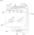
- the civil engineering device selected as an exemplary embodiment is designed as a vibration pile driver 1, which is connected to a hydraulic unit 2 in a hydraulic circuit 5.
- the vibration pile driver 1 comprises, in a known manner, a vibrator transmission 11 with shafts 12 arranged parallel to one another, which are provided with unbalances 13 and which can be driven by a hydraulic motor 14.
- a vibration transmission is for example in EP 1 967 292 A2 described.
- a clamping device 15 designed in the form of clamping pliers is arranged, which in known Way has a clamping cylinder 16 for clamping the pile.
- the hydraulic unit 1 comprises an internal combustion engine, in the present case a charged diesel engine 21, which drives a hydraulic pump 22.
- the hydraulic pump 22 is connected via hydraulic lines 51 of the hydraulic circuit 5 to the hydraulic motor 14 of the vibrator transmission 11 of the vibration pile driver 1.
- a second hydraulic unit 4 which comprises an electric motor 41 which drives a second hydraulic pump 42, is also arranged on the vibration pile driver 1.
- the electric motor 41 is connected to an accumulator 43 for the voltage supply.
- the hydraulic pump 42 operated by the electric motor 41 is connected to the clamping cylinder 16 of the clamping device 15 via hydraulic lines 52.
- a pressure booster 53 is arranged between the hydraulic pump 42 and the clamping cylinder 16 in the hydraulic line 52.
- a controller 3 is also arranged, which is connected to the electric motor 41 and the clamping cylinder 16 via control lines 31.
- the controller 3 is also connected to the accumulator 43.
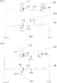
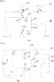
- two hydraulic pumps 22, 23, which are driven by the diesel engine 21, are arranged in the first hydraulic unit 2 are.
- the additional hydraulic pump 23 is connected to the clamping cylinder 16 of the clamping device 15 of the vibratory pile driver 1 via a check valve 54.
- the hydraulic pump 42 driven by the electric motor 41 is also connected to this clamping cylinder 16 via a check valve 54.
- the diesel engine 21 of the hydraulic unit 2 and the electric motor 41 of the hydraulic unit 4 are controlled via the controller 3. If, for example, the outside temperature is low, the engine is cold (corresponding to the engine oil temperature reported by sensor b) and the state of charge of the accumulator 43 low (corresponding to the state of charge reported by the sensor e), the diesel engine 21 is not switched off even during a break in operation.
- the controller 3 either automatically switches off the Diesel engine 21, or it will be the Operator is given a visual and / or acoustic signal that the diesel engine 21 can be switched off.
Landscapes
- Engineering & Computer Science (AREA)
- General Engineering & Computer Science (AREA)
- Life Sciences & Earth Sciences (AREA)
- Structural Engineering (AREA)
- Mechanical Engineering (AREA)
- Paleontology (AREA)
- General Life Sciences & Earth Sciences (AREA)
- Mining & Mineral Resources (AREA)
- Civil Engineering (AREA)
- Physics & Mathematics (AREA)
- Fluid Mechanics (AREA)
- Chemical & Material Sciences (AREA)
- Combustion & Propulsion (AREA)
- Agronomy & Crop Science (AREA)
- Environmental & Geological Engineering (AREA)
- Soil Sciences (AREA)
- Fluid-Pressure Circuits (AREA)
Description
- Die Erfindung betrifft ein Tiefbaugerät zum Einbringen von Rammgut in den Boden nach dem Oberbegriff des Patentanspruchs 1. Die Erfindung betrifft weiterhin ein Verfahren zur Betrieb eines solchen Tiefbaugerätes nach dem Oberbegriff des Patentanspruchs 10.
- Im Bauwesen werden Tiefbaugeräte mit unterschiedlichen Arbeitsgeräten mit hydraulischem Antrieb für Tiefbauarbeiten in einer hydraulischen Gruppe betrieben. Die hydraulische Gruppe besteht regelmäßig aus einer Hydraulikpumpe, die von einem Verbrennungsmotor, insbesondere einem aufgeladenen Dieselmotor angetrieben wird, einem Arbeitsgerät mit hydraulischem Antrieb, insbesondere einem Hydraulikmotor sowie einer Steuer- bzw. Regeleinheit. Die hydraulische Gruppe wird mit einem Fluid in einen Hydraulikkreislauf betrieben. Das Produkt aus Druck- und Volumenstrom des Fluids ergibt die hydraulische Leistung. Um die für das Arbeitsgerät erforderliche Leistung bereitstellen zu können, ist der die Hydraulikpumpe antreibende Verbrennungsmotor entsprechend groß dimensioniert.
- Als Arbeitsgeräte kommen insbesondere Vibrationsrammen bzw. Vibratoren zum Einsatz, um Objekte, wie beispielsweise Stahlprofile, in den Boden einzubringen oder aus dem Boden zu ziehen oder auch um Bodenmaterial zu verdichten. Der Boden wird durch Vibration angeregt und erreicht so einen "pseudoflüssigen" Zustand. Durch statische Auflast kann das Rammgut dann in den Baugrund gedrückt werden. Vibrationsrammen weisen regelmäßig linear wirkende Schwingungserreger auf, deren Fliehkraft durch rotierende Unwuchten generiert wird. Der Verlauf der Geschwindigkeit des linearen Schwingungserregers entspricht einer periodisch wiederkehrenden Funktion, beispielsweise einer Sinusfunktion. Die Schwingungserreger werden mit hydraulischen Drehantrieben betrieben, welche die Wellen, auf denen die Unwuchten angeordnet sind, in Rotation versetzen. Zur Aufnahme eines in den Boden einzubringenden Objektes weisen Vibrationsrammen eine Klemmzange auf, über welche die Schwingungen des Vibrators sowie die statische Auflast auf das aufgenommene Objekt übertragen werden.
- Bei Baustellen, die eine vibrationsfreie Methode fordern, beispielsweise in der Nähe von historischen Gebäuden unter Denkmalschutz oder Krankenhäusern, kommen hydraulische Pressen als Arbeitsgeräte zum Einsatz. Solche Hydropressen verfügen über eine Anordnung von Klemmzangen, die jeweils mit einem Hydraulikzylinder verbunden sind und der Aufnahme jeweils eines Objektes, beispielsweise einer Spundwandbohle dienen. Durch Betätigung der Hydraulikzylinder können die von den Klemmzangen aufgenommenen Objekte in den Boden gedrückt oder aus diesem herausgezogen werden.
- Die zur Aufnahme der in den Boden einzubringenden bzw. aus dem Boden herauszuziehenden Objekte angeordneten Klemmzangen sind über einen oder mehrere hydraulische Spannzylinder betätigbar, die ebenfalls über das Fluid der Hydraulikgruppe betrieben sind. Die Klemmzange hat eine große sicherheitstechnische Bedeutung. Um die sichere Fixierung eines in den Boden einzubringenden Objekts an dem Arbeitsgerät zu gewährleisten, ist eine kontinuierliche Druckversorgung des wenigstens einen Spannzylinders der Klemmzange zur Sicherstellung der erforderlichen Klemmkraft zu gewährleisten. Daher wird in der Praxis in Arbeitspausen des Tiefbaugerätes der Verbrennungsmotor zur Aufrechterhaltung des vergleichsweise geringen, für die Klemmkraft der Klammzangen erforderlichen Drucks, weiter betrieben wird, was einen erheblichen Verbrauch an Dieselkraftstoff zur Folge hat. Zur Reduzierung dieses erheblichen Dieselverbrauchs wird in der
DE 10 2013 103 715 A1 vorgeschlagen, auf Basis von Betriebsparametern des Arbeitsgerätes Betriebspausen zu erkennen und während einer Betriebspause des Verbrennungsmotors selbsttätig abzuschalten. Zur Sicherstellung des für die Klemmkraft der Klemmzange an dem Spannzylinders anliegenden erforderlichen statischen Drucks soll dieser überwacht werden und bei Absinken des Drucks unter einen vorgegebenen Wert soll der Verbrennungsmotor selbsttätig angeschaltet werden. Dabei soll der Dieselmotor nur abgeschaltet werden, wenn die Klemmzange geöffnet, also ohne Funktion oder die Funktion der Klemmzange über die Kontrolle des Klemmdrucks sichergestellt ist. Fällt der Klemmdruck infolge einer Leckage des Spannzylinders, wird der Dieselmotor angelassen und Öl in den Spannzylinder nachgespeist. - Nachteilig an dieser vorgeschlagenen Lösung ist, dass das Anlassen und der nachfolgende Betrieb des Verbrennungsmotors zur Wiederherstellung des für die Klemmkraft erforderlichen Drucks unverhältnismäßig viel Energie bzw. Dieselkraftstoff erfordert. Um wenige Milliliter Hydrauliköl nachzuspeisen, wird ein Dieselmotor mit mehreren hundert Kilowatt Kupplungsleistung angelassen. Allein für das Anlassen des Dieselmotors ist mehr Energie als für das Nachspeisen des Hydrauliköls erforderlich. Darüber hinaus weist der Dieselmotor einen Leerlaufverbrauch auf, der in einem sehr ungünstigen Verhältnis zu der zum Nachspeisen von Hydrauliköl erforderlichen Leistung steht. Hinzu kommt, dass der Dieselmotor durch die Schleppleistung der mit diesem verbundenen großen Hydraulikpumpen, die zum Antrieb des Arbeitsgerätes dimensioniert sind und regelmäßig mit dem Dieselmotor mitdrehen, belastet wird.
- Hier will die Erfindung Abhilfe schaffen. Der Erfindung liegt die Aufgabe zu Grunde, ein Tiefbaugerät bereitzustellen, bei dem insbesondere in Betriebspausen der Energieverbrauch bzw. Dieselverbrauch des Tiefbaugerätes reduziert ist. Gemäß der Erfindung wird diese Aufgabe durch ein Tiefbaugerät mit den Merkmalen des kennzeichnenden Teils des Patentanspruchs 1 gelöst.
- Mit der Erfindung ist ein Tiefbaugerät bereitgestellt, bei dem insbesondere in Betriebspausen der Energieverbrauch bzw. Dieselverbrauch des Tiefbaugerätes reduziert ist. Dadurch, dass eine weitere Hydraulikpumpe zum Aufbau des Spanndrucks des Spannzylinders der Spannvorrichtung angeordnet ist, die von einem Elektromotor betrieben ist, ist ein Ausgleich von Druckabfällen, beispielsweise infolge einer Leckage des Spannzylinders ohne ein Anlassen des Verbrennungsmotors ermöglicht. Der Elektromotor zum Betrieb der weiteren Hydraulikpumpe kann beispielsweise über den Akkumulator des Verbrennungsmotors gespeist werden, der regelmäßig für den erforderlichen Elektrostarter des Verbrennungsmotors vorhanden ist.
- In Weiterbildung der Erfindung ist die vom Elektromotor angetriebene Hydraulikpumpe zum Aufbau des Spanndrucks eine Radialkolbenpumpe. Hierdurch ist die Bereitstellung des für den Spannzylinder erforderlichen Hochdrucks ermöglicht.
- In Ausgestaltung der Erfindung ist die vom Elektromotor angetriebene Hydraulikpumpe zum Aufbau des Spanndrucks parallel zu einer vom Verbrennungsmotor angetriebenen Hydraulikpumpe zum Aufbau des Spanndrucks angeschlossen. Hierdurch ist eine redundante Anordnung erzielt, bei der der Spannzylinder ausschließlich, also auch im Betrieb des Arbeitsgeräts von der von dem Elektromotor betriebenen Hydraulikpumpe versorgt werden kann. Darüber hinaus ist durch die vom Elektromotor angetriebene Hydraulikpumpe auch bei einem Ausfall des Verbrennungsmotors oder der von diesem angetriebenen Hydraulikpumpe die Aufrechterhaltung des erforderlichen Spanndrucks gewährleistet.
- In weiterer Ausgestaltung der Erfindung ist in Fließrichtung des Hydraulikfluids hinter der elektrisch angetriebenen Hydraulikpumpe ein Druckübersetzer zur Erhöhung des von dieser bereitgestellten Hydraulikdrucks angeordnet. Hierdurch ist der Einsatz einer geringer dimensionierten Hydraulikpumpe ermöglicht.
- In Weiterbildung der Erfindung ist die elektrisch angetriebene Hydraulikpumpe derart angesteuert, dass sie - allein oder in Verbindung mit einem Druckübersetzer - einen höheren Druck bereitstellt, als die durch den Verbrennungsmotor betriebene Hydraulikpumpe zum Aufbau des Spanndrucks, wobei der maximale Spanndruck bevorzugt nur durch die elektrisch angetriebene Hydraulikpumpe bereitgestellt wird. Hierdurch ist eine geringere Dimensionierung der Einheit aus Elektromotor und Hydraulikpumpe zum Aufbau des Spanndrucks ermöglicht.
- In Ausgestaltung der Erfindung sind der Verbrennungsmotor und das Arbeitsgerät mit einer Steuerung verbunden, die eingerichtet ist, bei deaktiviertem Arbeitsgerät zumindest einen Betriebszustandswert abzufragen, um den Verbrennungsmotor selbsttätig anzuhalten oder das Anhalten des Verbrennungsmotors über ein Signal, insbesondere über eine Anzeige dem Bediener zu empfehlen, wenn der wenigstens eine Betriebszustand einem zugeordneten Vorgabewert entspricht. Vorteilhaft ist hierbei ein Temperatursensor zur Messung der Hydraulikfluidtemperatur und/oder ein Temperatursensor zur Messung der Verbrennungsmotoröltemperatur angeordnet, welcher Temperatursensor mit der Steuerung verbunden ist, wobei die Steuerung derart eingerichtet ist, dass bei Unterschreiten einer einem Temperatursensor zugeordneten Grenztemperatur ein Anhalten des Verbrennungsmotors oder eine Empfehlung zum Anhalten des Verbrennungsmotors nicht erfolgt.
- In weiterer Ausgestaltung der Erfindung ist ein Drucksensor zur kontinuierlichen Messung des Spanndrucks der Spannvorrichtung angeordnet, der mit einer Steuer- und Regeleinrichtungen verbunden ist, die derart eingerichtet ist, dass bei Absinken des Spanndrucks unter einen vorgegebenen Mindestdruckwert eine Druckerhöhung durch die von dem Elektromotor betriebene Pumpe auf einen vorgegebenen Solldruckwerk erfolgt. Hierdurch ist eine autarke Druckregelung über die von dem Elektromotor betriebene Hydraulikpumpe ermöglicht, ohne dass ein Anlassen des Verbrennungsmotors erforderlich ist.
- In Weiterbildung der Erfindung ist der Elektromotor über einen Akkumulator gespeist, der mit einer durch den Verbrennungsmotor betriebenen Ladevorrichtung verbunden ist, wobei ein Sensor zur kontinuierlichen Messung des Ladezustands des Akkumulators angeordnet ist, der mit einer Steuereinrichtung zur Ansteuerung des Verbrennungsmotors verbunden ist, die derart eingerichtet ist, dass bei Unterschreiten eines vorgegebenen minimalen Ladezustands des Ackumulators ein selbsttätiges Starten des Verbrennungsmotors erfolgt. Hierdurch ist ein zuverlässiger Betrieb des Elektromotors zum Antrieb der von dieser betriebenen Hydraulikpumpe gewährleistet.
- Der Erfindung liegt weiterhin die Aufgabe zugrunde, ein Verfahren zum Betrieb eines solchen Tiefbaugerätes zu schaffen, welches eine Reduzierung des erforderlichen Energie- bzw. Dieselbedarfs des Trägergerätes ermöglicht. Gemäß der Erfindung wird diese Aufgabe durch die Merkmale des kennzeichnenden Teils des Patentanspruchs 10 gelöst. Dadurch, dass der Spanndruck des Spannzylinders der Spannvorrichtung zumindest bei angehaltenem Verbrennungsmotor durch eine Hydraulikpumpe aufrechterhalten wird, die von einem Elektromotor betrieben wird, ist ein Anlassen des Verbrennungsmotors im Falle eines Druckabfalls des Spannzylinders der Spannvorrichtung nicht erforderlich. Beachtlich ist an dieser Stelle, dass der Energiebedarf zum Nachspeisen des Spannzylinders im Vergleich zu der zum Anlassen des Verbrennungsmotors erforderlichen Energie im Verhältnis etwa zwei Zehnerpotenzen geringer ist.
- In Weiterbildung der Erfindung wird als Betriebszustandswert der Öffnungszustand der Spannvorrichtung abgefragt, wobei der Verbrennungsmotor bei geschlossener Spannzange nur in dem Fall angehalten wird, wenn die über den Elektromotor betriebene Pumpe aktiviert ist. Hierdurch ist einem unbeabsichtigten Öffnen der Spannzange wirksam entgegengewirkt.
- In Ausgestaltung der Erfindung ist der Elektromotor über einen Akkumulator betrieben und als weiterer Betriebszustandswert wird der Ladezustand des Ackumulators abgefragt, wobei der Verbrennungsmotor bei geschlossener Spannzange nur in dem Fall angehalten wird, wenn der Ladezustand des Akkumulators über einen vorgegebenen Mindestladezustand liegt. Hierdurch ist ein zuverlässiger Betrieb des Elektromotors beim Anhalten des Verbrennungsmotors gewährleistet.
- In Weiterbildung der Erfindung wird als Betriebszustand fortlaufend ein Spanndruck der Spannvorrichtung abgefragt, wobei der Verbrennungsmotor angehalten wird, wenn bei geschlossener Spannvorrichtung der Spanndruck größer als ein vorgegebener Mindestdruck ist. Bevorzugt wird als zusätzlicher Betriebszustandswert eine Hydrauliköltemperatur und/oder eine Motoröltemperatur des Verbrennungsmotors und/oder eine Motorkühlmitteltemperatur des Verbrennungsmotors abgefragt, wobei der Verbrennungsmotor nicht abgeschaltet wird, wenn eine abgefragte Temperatur unterhalb einer zugeordneten Mindesttemperatur liegt.
- In Ausgestaltung der Erfindung wird der für den Betrieb des Spannzylinders erforderliche Hochdruck unabhängig vom Betriebszustand des Verbrennungsmotors durch die Hydraulikpumpe aufrechterhalten, die von einem Elektromotor betrieben wird. Hierdurch ist ein Anlassen des Verbrennungsmotors zur Herstellung des für den Betrieb des Spannzylinders erforderlichen Drucks vermieden.
- Andere Weiterbildungen und Ausgestaltungen der Erfindung sind in den übrigen Unteransprüchen angegeben. Ausführungsbeispiele der Erfindung sind in den Figuren dargestellt und werden nachfolgend im Einzelnen beschrieben. Es zeigen:
- Figur 1
- die schematische Darstellung eines Vibrationsrammgerätes mit angeordnetem Hydraulikaggregat;
- Figur 2
- eine schematische Detaildarstellung des Vibrationsrammgerätes aus
Figur 1 ; - Figur 3
- die schematische Darstellung eines Hydraulikschaltbildes des Vibrationsrammgerätes aus
Figur 1 ; - Figur 4
- die schematische Darstellung eines Hydraulikschaltbildes eines Vibrationsrammgerätes in einer weiteren Ausführungsform;
- Figur 5
- die schematische Darstellung eines Hydraulikschaltbildes eines Vibrationsrammgerätes in einer dritten Ausführungsform und
- Figur 6
- die schematische Darstellung des Hydraulikschaltbildes eines Vibrationsrammgerätes in einer vierten Ausführungsform.
- Das als Ausführungsbeispiel gewählte Tiefbaugerät ist als Vibrationsrammgerät 1 ausgebildet, das in einen Hydraulikkreislauf 5 mit einem Hydraulikaggregat 2 verbunden ist. Das Vibrationsrammgerät 1 umfasst in bekannter Art und Weise ein Vibratorgetriebel 11 mit parallel zueinander angeordneten Wellen 12, die mit Unwuchten 13 versehen sind und die über einen Hydraulikmotor 14 antreibbar sind. Ein derartiges Vibrationsgetriebe ist beispielsweise in der
EP 1 967 292 A2 beschrieben. An dem Gehäuse des Vibratorgetriebes 11 ist eine in Form einer Klemmzange ausgebildete Spannvorrichtung 15 angeordnet, die in bekannter Art und Weise einen Spannzylinder 16 zur Einspannung von Rammgut aufweist. - Das Hydraulikaggregat 1 umfasst einen Verbrennungsmotor, vorliegend einen aufgeladenen Dieselmotor 21, der eine Hydraulikpumpe 22 antreibt. Die Hydraulikpumpe 22 ist über Hydraulikleitungen 51 des Hydraulikkreislaufs 5 mit dem Hydraulikmotor 14 des Vibratorgetriebes 11 des Vibrationsrammgerätes 1 verbunden.
- An dem Vibrationsrammgerät 1 ist weiterhin ein zweites Hydraulikaggregat 4 angeordnet, das einen Elektromotor 41 umfasst, der eine zweite Hydraulikpumpe 42 antreibt. Zur Spannungsversorgung ist der Elektromotor 41 mit einem Akkumulator 43 verbunden. Die von dem Elektromotor 41 betriebene Hydraulikpumpe 42 ist über Hydraulikleitungen 52 mit den Spannzylinder 16 der Spannvorrichtung 15 verbunden. Zum Aufbau des erforderlichen Spanndrucks ist zwischen der Hydraulikpumpe 42 und dem Spannzylinder 16 in der Hydraulikleitung 52 ein Druckübersetzer 53 angeordnet. Zur Ansteuerung der Spannvorrichtung 15 ist weiterhin eine Steuerung 3 angeordnet, die über Steuerleitungen 31 mit dem Elektromotor 41 und dem Spannzylinder 16 verbunden ist. Weiterhin ist die Steuerung 3 mit dem Akkumulator 43 verbunden.
- In der vorliegenden Anordnung erfolgt eine vollständig getrennte Versorgung des Hydraulikmotors 14 des Vibratorgetriebes 11 durch die von dem Dieselmotor 21 angetriebene Hydraulikpumpe 22 einerseits sowie die Versorgung des Spannzylinders 16 der Spannvorrichtung 15 über die von den Elektromotor 41 angetriebene Hydraulikpumpe 42 andererseits. Bei Ausgestaltung der Hydraulikpumpe 42 als Hochdruckpumpe, beispielsweise als Radialkolbenpumpe kann der hydraulische Druckübersetzer entfallen, wie dies in
Figur 4 gezeigt ist. Hier ist zwischen Hydraulikpumpe 42 und Spannzylinder 16 lediglich ein Rückschlagventil 54 angeordnet. - Im Ausführungsbeispiel gemäß
Figur 5 sind in dem ersten Hydraulikaggregat 2 zwei Hydraulikpumpen 22, 23 angeordnet, die von dem Dieselmotor 21 angetrieben sind. Die zusätzliche Hydraulikpumpe 23 ist über ein Rückschlagventil 54 mit dem Spannzylinder 16 der Spannvorrichtung 15 des Vibrationsrammgerätes 1 verbunden. Zugleich ist die von dem Elektromotor 41 angetriebene Hydraulikpumpe 42 ebenfalls über ein Rückschlagventil 54 mit diesem Spannzylinder 16 verbunden. In dieser Konfiguration besteht die Möglichkeit, den Spannzylinder 16 auf herkömmliche Art mit der weiteren vom Dieselmotor 21 angetriebenen Hydraulikpumpe 23 zu füllen und ab Erreichen des mit dieser Hydraulikpumpe 23 realisierbaren Drucks den höheren Spannungsdruck mit der von dem Elektromotor 41 angetriebenen Hydraulikpumpe 42 aufzubauen. - Im Ausführungsbeispiel gemäß
Figur 6 wurde die zuvor beschriebene Anordnung nachFigur 5 durch einen hydraulischen Druckübersetzer 53 ergänzt, der dem Spannzylinder 16 in Fließrichtung des Hydraulikfluids vorgeschaltet angeordnet ist, wodurch eine kleinere Dimensionierung der weiteren Hydraulikpumpe 23 des ersten Hydraulikaggregats 2 sowie auch der Hydraulikpumpe 42 des zweiten Hydraulikaggregats 4 ermöglicht ist. Weiterhin ist die elektrische Versorgung des Elektromotors 41 über einen Akkumulator 43 in einem Stromkreis dargestellt. Die Steuerung 3 ist erweitert ausgebildet und an ihren Eingängen mit Sensoren zur Erfassung der Vibratorschwingweite (a), der Motoröltemperatur des Dieselmotors (b), des Spanndrucks des Spannzylinders (c), der Temperatur des Hydrauliköls (d) sowie des Ladezustands des Akkumulators (e) verbunden. In Abhängigkeit der Signale dieser Sensoren erfolgt die Ansteuerung des Dieselmotors 21 des Hydraulikaggregats 2 sowie des Elektromotors 41 des Hydraulikaggregats 4 über die Steuerung 3. Ist beispielsweise bei niedriger Außentemperatur der Motor kalt (entsprechend der vom Sensor b gemeldeten Motoröltemperatur) und der Ladezustand des Akkumulators 43 niedrig (entsprechend dem von dem Sensor e gemeldeten Ladezustand), wird der Dieselmotor 21 auch während einer Betriebspause nicht abgeschaltet. Meldet hingegen beispielsweise Sensor a eine Vibratorschwingweite von Null, Sensor b eine ausreichende Motoröltemperatur, Sensor c einen ausreichenden Spanndruck, Sensor d eine ausreichende Temperatur des Hydrauliköls sowie Sensor e einen ausreichenden Ladezustand des Akkumulators 43, so erfolgt durch die Steuerung 3 entweder eine selbsttätige Abschaltung des Dieselmotors 21, oder es wird dem Bediener ein optisches und/oder akustisches Signal gegeben, dass der Dieselmotor 21 abgeschaltet werden kann.
Claims (15)
- Tiefbaugerät, umfassend ein Hydraulikaggregat (2) mit einem Verbrennungsmotor (21) und einer von dem Verbrennungsmotor (21) angetriebenen Hydraulikpumpe (22), ein mit dem Hydraulikaggregat (2) in einem Hydraulikkreislauf (5) verbundenes Arbeitsgerät (1) zum Einbringen von Rammgut in den Boden, eine an dem Arbeitsgerät (1) angeschlossene Spannvorrichtung (15) zur klemmenden Aufnahme eines Rammgutes, die einen hydraulischen Spannzylinder (16) aufweist sowie eine Steuerung (3) zum Öffnen und Schließen der hydraulischen Spannvorrichtung (15), dadurch gekennzeichnet, dass eine weitere Hydraulikpumpe (42) zum Aufbau des Spanndrucks des Spannzylinders (16) der Spannvorrichtung (15) angeordnet ist, die von einem Elektromotor (41) betrieben ist.
- Tiefbaugerät nach Anspruch 1, dadurch gekennzeichnet, dass die vom Elektromotor (41) angetriebene Hydraulikpumpe (42) zum Aufbau des Spanndrucks eine Radialkolbenpumpe ist.
- Tiefbaugerät nach Anspruch 1 oder 2, dadurch gekennzeichnet, dass die vom Elektromotor (41) angetriebene Hydraulikpumpe (42) zum Aufbau des Spanndrucks parallel zu einer vom Verbrennungsmotor (21) angetriebenen Hydraulikpumpe (23) zum Aufbau des Spanndrucks angeschlossen ist.
- Tiefbaugerät nach einem der vorgenannten Ansprüche, dadurch gekennzeichnet, dass in Fließrichtung des Hydraulikfluids hinter der elektrisch angetriebenen Hydraulikpumpe (42) ein Druckübersetzer (53) zur Erhöhung des von dieser bereitgestellten Hydraulikdrucks angeordnet ist.
- Tiefbaugerät nach Anspruch 3 oder 4, dadurch gekennzeichnet, dass die elektrisch angetriebene Hydraulikpumpe (42) derart angesteuert ist, dass sie, vorzugsweise in Verbindung mit einem Druckübersetzer (53), einen höheren Druck bereitstellt, als die durch den Verbrennungsmotor (21) betriebene Hydraulikpumpe (23) zum Aufbau des Spanndrucks, wobei der maximale Spanndruck bevorzugt nur durch die elektrisch angetriebene Hydraulikpumpe (42) bereitgestellt wird.
- Tiefbaugerät nach einem der vorgenannten Ansprüche, dadurch gekennzeichnet, dass der Verbrennungsmotor (21) und das Arbeitsgerät (1) mit einer Steuerung (3) verbunden sind, die eingerichtet ist, bei deaktiviertem Arbeitsgerät zumindest einen Betriebszustandswert abzufragen und den Verbrennungsmotor (21) selbsttätig anzuhalten oder das Anhalten des Verbrennungsmotors (21) über ein Signal, insbesondere über eine Anzeige, dem Bediener zu empfehlen, wenn der wenigstens eine Betriebszustand einem zugeordneten Vorgabewert entspricht.
- Tiefbaugerät nach Anspruch 6, dadurch gekennzeichnet, dass ein Temperatursensor (d) zur Messung der Hydraulikfluidtemperatur und/oder ein Temperatursensor (b) zur Messung der Verbrennungsmotoröltemperatur angeordnet ist, welcher Temperatursensor mit der Steuerung (3) verbunden ist, wobei die Steuerung derart eingerichtet ist, dass bei Unterschreiten einer einem Temperatursensor (b, d) zugeordneten Grenztemperatur ein Anhalten des Verbrennungsmotors (21) oder eine Empfehlung zum Anhalten des Verbrennungsmotors (21) nicht erfolgt.
- Tiefbaugerät nach einem der vorgenannten Ansprüche, dadurch gekennzeichnet, dass ein Drucksensor (c) zur kontinuierlichen Messung des Spanndrucks der Spannvorrichtung (15) angeordnet ist, der mit einer Steuer- und Regeleinrichtung verbunden ist, die derart eingerichtet ist, dass bei Absinken des Spanndrucks unter einen vorgegebenen Mindestdruckwert eine Druckerhöhung durch die von dem Elektromotor (41) betriebene Hydraulikpumpe (42) auf einen vorgegebenen Solldruckwert erfolgt.
- Tiefbaugerät nach einem der vorgenannten Ansprüche, dadurch gekennzeichnet, dass der Elektromotor (41) über einen Akkumulator (43) gespeist ist, der mit einer durch den Verbrennungsmotor (21) betriebenen Ladevorrichtung verbunden ist, wobei ein Sensor (e) zur kontinuierlichen Messung des Ladezustands des Akkumulators (43) angeordnet ist, der mit einer Steuereinrichtung (3) zur Ansteuerung des Verbrennungsmotors (21) verbunden ist, die derart eingerichtet ist, dass bei Unterschreiten eines vorgegebenen Minimalladezustands des Akkumulators (43) ein selbsttätiges Starten des Verbrennungsmotors (21) erfolgt.
- Verfahren zum Betrieb eines Tiefbaugerätes nach einem der vorgenannten Ansprüche, wobei die Steuerung (3) in einer Betriebspause bei deaktiviertem Arbeitsgerät (1) zumindest einen Betriebszustandswert abfragt und den Verbrennungsmotor (21) selbsttätig anhält oder das Anhalten des Verbrennungsmotors (21) dem Bediener über ein Signal, insbesondere über eine Anzeige, empfiehlt, wenn der Betriebszustandswert einem Vorgabewert entspricht, dadurch gekennzeichnet, dass der Spanndruck des Spannzylinders (16) der Spannvorrichtung (15) zumindest bei angehaltenem Verbrennungsmotor (21) durch die Hydraulikpumpe (42) aufrechterhalten wird, die von einem Elektromotor (41) betrieben wird.
- Verfahren nach Anspruch 10, dadurch gekennzeichnet, dass als Betriebszustandswert der Öffnungszustand der Spannvorrichtung (15) abgefragt wird, wobei der Verbrennungsmotor (21) bei geschlossener Spannvorrichtung (15) nur in dem Fall angehalten wird, wenn die über den Elektromotor (41) betriebene Hydraulikpumpe (42) aktiviert ist.
- Verfahren nach Anspruch 11, dadurch gekennzeichnet, dass der Elektromotor (41) über einen Akkumulator (43) betrieben ist und dass als weiterer Betriebszustandswert der Ladezustand des Akkumulators (43) abgefragt wird, wobei der Verbrennungsmotor (21) bei geschlossener Spannvorrichtung (15) nur in dem Fall angehalten wird, wenn der Ladezustand des Akkumulators (43) über einem vorgegebenen Mindestladezustand liegt.
- Verfahren nach einem der Ansprüche 10 bis 12, dadurch gekennzeichnet, dass als Betriebszustand fortlaufend ein Spanndruck der Spannvorrichtung (15) abgefragt wird, wobei der Verbrennungsmotor (21) angehalten wird, wenn bei geschlossener Spannvorrichtung (15) der Spanndruck größer als ein vorgegebener Mindestdruck ist.
- Verfahren nach einem der Ansprüche 10 bis 13, dadurch gekennzeichnet, dass als zusätzlicher Betriebszustandswert die Hydrauliköltemperatur und/oder die Motoröltemperatur des Verbrennungsmotors (21) und/oder die Motorkühlmitteltemperatur des Verbrennungsmotors (21) abgefragt wird, wobei der Verbrennungsmotor (21) nicht abgeschaltet wird, wenn eine abgefragte Temperatur unterhalb einer zugeordneten Mindesttemperatur liegt.
- Verfahren nach einem der Ansprüche 10 bis 14, dadurch gekennzeichnet, dass der für den Betrieb des Spannzylinders (16) erforderliche Hochdruck unabhängig vom Betriebszustand des Verbrennungsmotors (21) durch die Hydraulikpumpe (42) aufrechterhalten wird, die von dem Elektromotor (41) betrieben wird.
Priority Applications (2)
| Application Number | Priority Date | Filing Date | Title |
|---|---|---|---|
| EP19157538.0A EP3696327B1 (de) | 2019-02-15 | 2019-02-15 | Tiefbaugerät |
| US16/739,508 US10988908B2 (en) | 2019-02-15 | 2020-01-10 | Underground construction device |
Applications Claiming Priority (1)
| Application Number | Priority Date | Filing Date | Title |
|---|---|---|---|
| EP19157538.0A EP3696327B1 (de) | 2019-02-15 | 2019-02-15 | Tiefbaugerät |
Publications (2)
| Publication Number | Publication Date |
|---|---|
| EP3696327A1 EP3696327A1 (de) | 2020-08-19 |
| EP3696327B1 true EP3696327B1 (de) | 2021-02-24 |
Family
ID=65443792
Family Applications (1)
| Application Number | Title | Priority Date | Filing Date |
|---|---|---|---|
| EP19157538.0A Active EP3696327B1 (de) | 2019-02-15 | 2019-02-15 | Tiefbaugerät |
Country Status (2)
| Country | Link |
|---|---|
| US (1) | US10988908B2 (de) |
| EP (1) | EP3696327B1 (de) |
Families Citing this family (2)
| Publication number | Priority date | Publication date | Assignee | Title |
|---|---|---|---|---|
| JP7715627B2 (ja) * | 2021-12-27 | 2025-07-30 | 日本車輌製造株式会社 | 杭打機の油圧駆動装置 |
| EP4675079A1 (de) * | 2024-07-03 | 2026-01-07 | ABI Anlagentechnik-Baumaschinen-Industriebedarf Maschinenfabrik und Vertriebsgesellschaft mbH | Spezialtiefbaugerät und verfahren zum betrieb eines spezialtiefbaugerätes |
Family Cites Families (16)
| Publication number | Priority date | Publication date | Assignee | Title |
|---|---|---|---|---|
| US3828864A (en) * | 1973-02-26 | 1974-08-13 | H & M Vibro Inc | Pile driver and extractor |
| US4100974A (en) * | 1977-01-06 | 1978-07-18 | Pepe Charles R | Machine suspended from a crane or similar device for driving and extracting piling and the like |
| JPS5516189A (en) * | 1978-07-21 | 1980-02-04 | Hisao Inoue | Pile driver utilizing hydraulic vibration |
| US4819740A (en) * | 1987-11-16 | 1989-04-11 | Vulcan Iron Works Inc. | Vibratory hammer/extractor |
| CN2644507Y (zh) * | 2003-07-17 | 2004-09-29 | 福建省建筑科学研究院 | 多功能组合搅拌桩机 |
| US7168890B1 (en) * | 2004-01-20 | 2007-01-30 | American Piledriving Equipment, Inc. | Eccentric vibration system with resonance control |
| DE202007003532U1 (de) | 2007-03-07 | 2007-07-05 | Abi Gmbh | Schwingungserreger |
| EP1990100B1 (de) * | 2007-05-10 | 2009-09-16 | BAUER Maschinen GmbH | Baumaschine zum Erzeugen von Schwingungen |
| FR2918473B1 (fr) * | 2007-07-03 | 2009-10-30 | Ptc Sa | Systeme d'asservissement d'un groupe hydraulique alimentant en fluide hydraulique un vibrateur. |
| DE102012104125A1 (de) * | 2012-05-10 | 2013-11-14 | Dieffenbacher GmbH Maschinen- und Anlagenbau | Verfahren zum Betreiben einer hydraulischen Presse und eine hydraulische Presse |
| US9249551B1 (en) * | 2012-11-30 | 2016-02-02 | American Piledriving Equipment, Inc. | Concrete sheet pile clamp assemblies and methods and pile driving systems for concrete sheet piles |
| DE102013103715B4 (de) * | 2013-04-12 | 2016-12-08 | Thyssenkrupp Tiefbautechnik Gmbh | Verfahren zum Betrieb einer Vibrationsrammanordnung |
| JP6356634B2 (ja) * | 2015-06-02 | 2018-07-11 | 日立建機株式会社 | 作業機械の油圧駆動装置 |
| CA3019280A1 (en) * | 2016-04-08 | 2017-10-12 | Junttan Oy | A method for controlling the driving engine and hydraulic pumps of a hydraulic machine, as well as a pile driving rig |
| EP3418451B1 (de) * | 2017-06-22 | 2019-07-24 | ABI Anlagentechnik-Baumaschinen-Industriebedarf Maschinenfabrik und Vertriebsgesellschaft mbH | Arbeitsgerät mit hydraulischem antrieb für tiefbauarbeiten |
| US11208976B2 (en) * | 2019-01-16 | 2021-12-28 | Ford Global Technologies, Llc | Methods and systems for controlling a stop/start engine |
-
2019
- 2019-02-15 EP EP19157538.0A patent/EP3696327B1/de active Active
-
2020
- 2020-01-10 US US16/739,508 patent/US10988908B2/en active Active
Non-Patent Citations (1)
| Title |
|---|
| None * |
Also Published As
| Publication number | Publication date |
|---|---|
| US20200263379A1 (en) | 2020-08-20 |
| US10988908B2 (en) | 2021-04-27 |
| EP3696327A1 (de) | 2020-08-19 |
Similar Documents
| Publication | Publication Date | Title |
|---|---|---|
| DE112007001729B4 (de) | Verfahren zum Betreiben einer Fluidarbeitsmaschine und eine Fluidarbeitsmaschine | |
| DE102019127714B3 (de) | Antriebsstrang mit Hydraulikeinheit | |
| EP2918874B1 (de) | Verfahren zum Betreiben eines Hydrauliksystems eines Automatikgetriebes | |
| EP3696327B1 (de) | Tiefbaugerät | |
| DE102013103722A1 (de) | Vibrationsrammanordnung sowie Verfahren zum Betrieb der Vibrationsrammanordnung | |
| DE102014211335A1 (de) | Drehmoment zum anschleppen der kraftmaschine mit bezug auf eine kraftmaschinenabschaltposition | |
| EP3504434B1 (de) | Pumpstation für eine pipeline und verfahren zum starten eines verbrennungsmotors in einer pumpstation | |
| DE102017115484B3 (de) | Verfahren zur Steuerung eines Aktors sowie Kraftfahrzeug mit einem Aktor | |
| WO2013127452A1 (de) | Verfahren zum betrieb einer hydraulikpumpenanordnung sowie hydraulikpumpenanordnung | |
| DE19805299A1 (de) | Elektronische Regeleinrichtung | |
| DE4405688A1 (de) | Anlassersteuerung | |
| EP1980671A2 (de) | Bodenverdichtungsgerät in Form einer Vibrationsplatte | |
| EP1722036A2 (de) | Bodenverdichtungsgerät | |
| EP1250493A1 (de) | Handgeführtes arbeitsgerät mit automatischer drehzahleinstellung | |
| EP2984240B1 (de) | Verfahren zum betrieb einer vibrationsrammanordnung | |
| DE102008040587B4 (de) | Antriebsanordnung für ein Kraftfahrzeug, sowie Verfahren zum Betrieb einer Antriebsanordnung für ein Kraftfahrzeug | |
| DE102014001369B4 (de) | Mobile hydraulische Baumaschine | |
| DE102011111924B4 (de) | Baumaschine, insbesondere Radlader oder Walze | |
| WO2020157046A1 (de) | Mobile arbeitsmaschine und verfahren zum betreiben einer solchen | |
| DE102014204427A1 (de) | Maschine zur Förderung von Dickstoffen | |
| DE102019100370A1 (de) | Verfahren zum Betrieb einer Pumpe in einem Kühlmodus und einem Aktormodus, entsprechendes Pumpensystem | |
| DE10141740B4 (de) | Kraftfahrzeug mit einem Brennstoffzellensystem | |
| DE954117C (de) | Sicherheitsvorrichtung fuer eine Brennkraftanlage mit Freiflugkolben-Treibgaserzeuger und z.B. als Turbine ausgebildeter Kraftmaschine | |
| EP3988227B1 (de) | Blindnietverbinder-setzeinrichtung | |
| DE102011115448A1 (de) | Verfahren für den Betrieb einer pneumatischen Anlasservorrichtung für Verbrennungsmotoren und Vorrichtung zur Durchführung des Verfahrens |
Legal Events
| Date | Code | Title | Description |
|---|---|---|---|
| PUAI | Public reference made under article 153(3) epc to a published international application that has entered the european phase |
Free format text: ORIGINAL CODE: 0009012 |
|
| STAA | Information on the status of an ep patent application or granted ep patent |
Free format text: STATUS: REQUEST FOR EXAMINATION WAS MADE |
|
| 17P | Request for examination filed |
Effective date: 20190522 |
|
| AK | Designated contracting states |
Kind code of ref document: A1 Designated state(s): AL AT BE BG CH CY CZ DE DK EE ES FI FR GB GR HR HU IE IS IT LI LT LU LV MC MK MT NL NO PL PT RO RS SE SI SK SM TR |
|
| AX | Request for extension of the european patent |
Extension state: BA ME |
|
| GRAP | Despatch of communication of intention to grant a patent |
Free format text: ORIGINAL CODE: EPIDOSNIGR1 |
|
| STAA | Information on the status of an ep patent application or granted ep patent |
Free format text: STATUS: GRANT OF PATENT IS INTENDED |
|
| INTG | Intention to grant announced |
Effective date: 20201027 |
|
| GRAS | Grant fee paid |
Free format text: ORIGINAL CODE: EPIDOSNIGR3 |
|
| GRAA | (expected) grant |
Free format text: ORIGINAL CODE: 0009210 |
|
| STAA | Information on the status of an ep patent application or granted ep patent |
Free format text: STATUS: THE PATENT HAS BEEN GRANTED |
|
| AK | Designated contracting states |
Kind code of ref document: B1 Designated state(s): AL AT BE BG CH CY CZ DE DK EE ES FI FR GB GR HR HU IE IS IT LI LT LU LV MC MK MT NL NO PL PT RO RS SE SI SK SM TR |
|
| REG | Reference to a national code |
Ref country code: CH Ref legal event code: EP |
|
| REG | Reference to a national code |
Ref country code: DE Ref legal event code: R096 Ref document number: 502019000831 Country of ref document: DE |
|
| REG | Reference to a national code |
Ref country code: AT Ref legal event code: REF Ref document number: 1364591 Country of ref document: AT Kind code of ref document: T Effective date: 20210315 |
|
| REG | Reference to a national code |
Ref country code: IE Ref legal event code: FG4D Free format text: LANGUAGE OF EP DOCUMENT: GERMAN |
|
| REG | Reference to a national code |
Ref country code: NL Ref legal event code: FP |
|
| REG | Reference to a national code |
Ref country code: LT Ref legal event code: MG9D |
|
| PG25 | Lapsed in a contracting state [announced via postgrant information from national office to epo] |
Ref country code: LT Free format text: LAPSE BECAUSE OF FAILURE TO SUBMIT A TRANSLATION OF THE DESCRIPTION OR TO PAY THE FEE WITHIN THE PRESCRIBED TIME-LIMIT Effective date: 20210224 Ref country code: PT Free format text: LAPSE BECAUSE OF FAILURE TO SUBMIT A TRANSLATION OF THE DESCRIPTION OR TO PAY THE FEE WITHIN THE PRESCRIBED TIME-LIMIT Effective date: 20210624 Ref country code: NO Free format text: LAPSE BECAUSE OF FAILURE TO SUBMIT A TRANSLATION OF THE DESCRIPTION OR TO PAY THE FEE WITHIN THE PRESCRIBED TIME-LIMIT Effective date: 20210524 Ref country code: HR Free format text: LAPSE BECAUSE OF FAILURE TO SUBMIT A TRANSLATION OF THE DESCRIPTION OR TO PAY THE FEE WITHIN THE PRESCRIBED TIME-LIMIT Effective date: 20210224 Ref country code: GR Free format text: LAPSE BECAUSE OF FAILURE TO SUBMIT A TRANSLATION OF THE DESCRIPTION OR TO PAY THE FEE WITHIN THE PRESCRIBED TIME-LIMIT Effective date: 20210525 Ref country code: FI Free format text: LAPSE BECAUSE OF FAILURE TO SUBMIT A TRANSLATION OF THE DESCRIPTION OR TO PAY THE FEE WITHIN THE PRESCRIBED TIME-LIMIT Effective date: 20210224 Ref country code: BG Free format text: LAPSE BECAUSE OF FAILURE TO SUBMIT A TRANSLATION OF THE DESCRIPTION OR TO PAY THE FEE WITHIN THE PRESCRIBED TIME-LIMIT Effective date: 20210524 |
|
| PG25 | Lapsed in a contracting state [announced via postgrant information from national office to epo] |
Ref country code: PL Free format text: LAPSE BECAUSE OF FAILURE TO SUBMIT A TRANSLATION OF THE DESCRIPTION OR TO PAY THE FEE WITHIN THE PRESCRIBED TIME-LIMIT Effective date: 20210224 Ref country code: RS Free format text: LAPSE BECAUSE OF FAILURE TO SUBMIT A TRANSLATION OF THE DESCRIPTION OR TO PAY THE FEE WITHIN THE PRESCRIBED TIME-LIMIT Effective date: 20210224 Ref country code: LV Free format text: LAPSE BECAUSE OF FAILURE TO SUBMIT A TRANSLATION OF THE DESCRIPTION OR TO PAY THE FEE WITHIN THE PRESCRIBED TIME-LIMIT Effective date: 20210224 Ref country code: SE Free format text: LAPSE BECAUSE OF FAILURE TO SUBMIT A TRANSLATION OF THE DESCRIPTION OR TO PAY THE FEE WITHIN THE PRESCRIBED TIME-LIMIT Effective date: 20210224 |
|
| PG25 | Lapsed in a contracting state [announced via postgrant information from national office to epo] |
Ref country code: IS Free format text: LAPSE BECAUSE OF FAILURE TO SUBMIT A TRANSLATION OF THE DESCRIPTION OR TO PAY THE FEE WITHIN THE PRESCRIBED TIME-LIMIT Effective date: 20210624 |
|
| PG25 | Lapsed in a contracting state [announced via postgrant information from national office to epo] |
Ref country code: SM Free format text: LAPSE BECAUSE OF FAILURE TO SUBMIT A TRANSLATION OF THE DESCRIPTION OR TO PAY THE FEE WITHIN THE PRESCRIBED TIME-LIMIT Effective date: 20210224 Ref country code: EE Free format text: LAPSE BECAUSE OF FAILURE TO SUBMIT A TRANSLATION OF THE DESCRIPTION OR TO PAY THE FEE WITHIN THE PRESCRIBED TIME-LIMIT Effective date: 20210224 Ref country code: CZ Free format text: LAPSE BECAUSE OF FAILURE TO SUBMIT A TRANSLATION OF THE DESCRIPTION OR TO PAY THE FEE WITHIN THE PRESCRIBED TIME-LIMIT Effective date: 20210224 |
|
| REG | Reference to a national code |
Ref country code: DE Ref legal event code: R097 Ref document number: 502019000831 Country of ref document: DE |
|
| PG25 | Lapsed in a contracting state [announced via postgrant information from national office to epo] |
Ref country code: SK Free format text: LAPSE BECAUSE OF FAILURE TO SUBMIT A TRANSLATION OF THE DESCRIPTION OR TO PAY THE FEE WITHIN THE PRESCRIBED TIME-LIMIT Effective date: 20210224 Ref country code: RO Free format text: LAPSE BECAUSE OF FAILURE TO SUBMIT A TRANSLATION OF THE DESCRIPTION OR TO PAY THE FEE WITHIN THE PRESCRIBED TIME-LIMIT Effective date: 20210224 Ref country code: DK Free format text: LAPSE BECAUSE OF FAILURE TO SUBMIT A TRANSLATION OF THE DESCRIPTION OR TO PAY THE FEE WITHIN THE PRESCRIBED TIME-LIMIT Effective date: 20210224 |
|
| PLBE | No opposition filed within time limit |
Free format text: ORIGINAL CODE: 0009261 |
|
| STAA | Information on the status of an ep patent application or granted ep patent |
Free format text: STATUS: NO OPPOSITION FILED WITHIN TIME LIMIT |
|
| PG25 | Lapsed in a contracting state [announced via postgrant information from national office to epo] |
Ref country code: AL Free format text: LAPSE BECAUSE OF FAILURE TO SUBMIT A TRANSLATION OF THE DESCRIPTION OR TO PAY THE FEE WITHIN THE PRESCRIBED TIME-LIMIT Effective date: 20210224 Ref country code: ES Free format text: LAPSE BECAUSE OF FAILURE TO SUBMIT A TRANSLATION OF THE DESCRIPTION OR TO PAY THE FEE WITHIN THE PRESCRIBED TIME-LIMIT Effective date: 20210224 |
|
| 26N | No opposition filed |
Effective date: 20211125 |
|
| PG25 | Lapsed in a contracting state [announced via postgrant information from national office to epo] |
Ref country code: IT Free format text: LAPSE BECAUSE OF FAILURE TO SUBMIT A TRANSLATION OF THE DESCRIPTION OR TO PAY THE FEE WITHIN THE PRESCRIBED TIME-LIMIT Effective date: 20210224 |
|
| PG25 | Lapsed in a contracting state [announced via postgrant information from national office to epo] |
Ref country code: IS Free format text: LAPSE BECAUSE OF FAILURE TO SUBMIT A TRANSLATION OF THE DESCRIPTION OR TO PAY THE FEE WITHIN THE PRESCRIBED TIME-LIMIT Effective date: 20210624 |
|
| PG25 | Lapsed in a contracting state [announced via postgrant information from national office to epo] |
Ref country code: MC Free format text: LAPSE BECAUSE OF FAILURE TO SUBMIT A TRANSLATION OF THE DESCRIPTION OR TO PAY THE FEE WITHIN THE PRESCRIBED TIME-LIMIT Effective date: 20210224 |
|
| REG | Reference to a national code |
Ref country code: CH Ref legal event code: PL |
|
| REG | Reference to a national code |
Ref country code: BE Ref legal event code: MM Effective date: 20220228 |
|
| PG25 | Lapsed in a contracting state [announced via postgrant information from national office to epo] |
Ref country code: LU Free format text: LAPSE BECAUSE OF NON-PAYMENT OF DUE FEES Effective date: 20220215 |
|
| PG25 | Lapsed in a contracting state [announced via postgrant information from national office to epo] |
Ref country code: LI Free format text: LAPSE BECAUSE OF NON-PAYMENT OF DUE FEES Effective date: 20220228 Ref country code: IE Free format text: LAPSE BECAUSE OF NON-PAYMENT OF DUE FEES Effective date: 20220215 Ref country code: CH Free format text: LAPSE BECAUSE OF NON-PAYMENT OF DUE FEES Effective date: 20220228 |
|
| PG25 | Lapsed in a contracting state [announced via postgrant information from national office to epo] |
Ref country code: BE Free format text: LAPSE BECAUSE OF NON-PAYMENT OF DUE FEES Effective date: 20220228 |
|
| P01 | Opt-out of the competence of the unified patent court (upc) registered |
Effective date: 20230513 |
|
| GBPC | Gb: european patent ceased through non-payment of renewal fee |
Effective date: 20230215 |
|
| PG25 | Lapsed in a contracting state [announced via postgrant information from national office to epo] |
Ref country code: GB Free format text: LAPSE BECAUSE OF NON-PAYMENT OF DUE FEES Effective date: 20230215 |
|
| PG25 | Lapsed in a contracting state [announced via postgrant information from national office to epo] |
Ref country code: GB Free format text: LAPSE BECAUSE OF NON-PAYMENT OF DUE FEES Effective date: 20230215 |
|
| PG25 | Lapsed in a contracting state [announced via postgrant information from national office to epo] |
Ref country code: MK Free format text: LAPSE BECAUSE OF FAILURE TO SUBMIT A TRANSLATION OF THE DESCRIPTION OR TO PAY THE FEE WITHIN THE PRESCRIBED TIME-LIMIT Effective date: 20210224 Ref country code: CY Free format text: LAPSE BECAUSE OF FAILURE TO SUBMIT A TRANSLATION OF THE DESCRIPTION OR TO PAY THE FEE WITHIN THE PRESCRIBED TIME-LIMIT Effective date: 20210224 |
|
| PG25 | Lapsed in a contracting state [announced via postgrant information from national office to epo] |
Ref country code: HU Free format text: LAPSE BECAUSE OF FAILURE TO SUBMIT A TRANSLATION OF THE DESCRIPTION OR TO PAY THE FEE WITHIN THE PRESCRIBED TIME-LIMIT; INVALID AB INITIO Effective date: 20190215 |
|
| PG25 | Lapsed in a contracting state [announced via postgrant information from national office to epo] |
Ref country code: TR Free format text: LAPSE BECAUSE OF FAILURE TO SUBMIT A TRANSLATION OF THE DESCRIPTION OR TO PAY THE FEE WITHIN THE PRESCRIBED TIME-LIMIT Effective date: 20210224 |
|
| PG25 | Lapsed in a contracting state [announced via postgrant information from national office to epo] |
Ref country code: MT Free format text: LAPSE BECAUSE OF FAILURE TO SUBMIT A TRANSLATION OF THE DESCRIPTION OR TO PAY THE FEE WITHIN THE PRESCRIBED TIME-LIMIT Effective date: 20210224 |
|
| PG25 | Lapsed in a contracting state [announced via postgrant information from national office to epo] |
Ref country code: SI Free format text: LAPSE BECAUSE OF FAILURE TO SUBMIT A TRANSLATION OF THE DESCRIPTION OR TO PAY THE FEE WITHIN THE PRESCRIBED TIME-LIMIT Effective date: 20210224 |
|
| PGFP | Annual fee paid to national office [announced via postgrant information from national office to epo] |
Ref country code: NL Payment date: 20260218 Year of fee payment: 8 |
|
| PGFP | Annual fee paid to national office [announced via postgrant information from national office to epo] |
Ref country code: DE Payment date: 20260130 Year of fee payment: 8 |
|
| PGFP | Annual fee paid to national office [announced via postgrant information from national office to epo] |
Ref country code: AT Payment date: 20260216 Year of fee payment: 8 |
|
| PGFP | Annual fee paid to national office [announced via postgrant information from national office to epo] |
Ref country code: FR Payment date: 20260223 Year of fee payment: 8 |