EP3696120B1 - Temporary storage and separation device for wheels on track line and wheel transfer track line - Google Patents
Temporary storage and separation device for wheels on track line and wheel transfer track line Download PDFInfo
- Publication number
- EP3696120B1 EP3696120B1 EP20154492.1A EP20154492A EP3696120B1 EP 3696120 B1 EP3696120 B1 EP 3696120B1 EP 20154492 A EP20154492 A EP 20154492A EP 3696120 B1 EP3696120 B1 EP 3696120B1
- Authority
- EP
- European Patent Office
- Prior art keywords
- connection rod
- blocking lever
- turntable
- wheels
- movably connected
- Prior art date
- Legal status (The legal status is an assumption and is not a legal conclusion. Google has not performed a legal analysis and makes no representation as to the accuracy of the status listed.)
- Active
Links
Images



Classifications
-
- B—PERFORMING OPERATIONS; TRANSPORTING
- B65—CONVEYING; PACKING; STORING; HANDLING THIN OR FILAMENTARY MATERIAL
- B65G—TRANSPORT OR STORAGE DEVICES, e.g. CONVEYORS FOR LOADING OR TIPPING, SHOP CONVEYOR SYSTEMS OR PNEUMATIC TUBE CONVEYORS
- B65G63/00—Transferring or trans-shipping at storage areas, railway yards or harbours or in opening mining cuts; Marshalling yard installations
- B65G63/002—Transferring or trans-shipping at storage areas, railway yards or harbours or in opening mining cuts; Marshalling yard installations for articles
-
- B—PERFORMING OPERATIONS; TRANSPORTING
- B65—CONVEYING; PACKING; STORING; HANDLING THIN OR FILAMENTARY MATERIAL
- B65G—TRANSPORT OR STORAGE DEVICES, e.g. CONVEYORS FOR LOADING OR TIPPING, SHOP CONVEYOR SYSTEMS OR PNEUMATIC TUBE CONVEYORS
- B65G47/00—Article or material-handling devices associated with conveyors; Methods employing such devices
- B65G47/22—Devices influencing the relative position or the attitude of articles during transit by conveyors
- B65G47/26—Devices influencing the relative position or the attitude of articles during transit by conveyors arranging the articles, e.g. varying spacing between individual articles
- B65G47/28—Devices influencing the relative position or the attitude of articles during transit by conveyors arranging the articles, e.g. varying spacing between individual articles during transit by a single conveyor
- B65G47/29—Devices influencing the relative position or the attitude of articles during transit by conveyors arranging the articles, e.g. varying spacing between individual articles during transit by a single conveyor by temporarily stopping movement
- B65G47/295—Devices influencing the relative position or the attitude of articles during transit by conveyors arranging the articles, e.g. varying spacing between individual articles during transit by a single conveyor by temporarily stopping movement by means of at least two stopping elements
-
- B—PERFORMING OPERATIONS; TRANSPORTING
- B65—CONVEYING; PACKING; STORING; HANDLING THIN OR FILAMENTARY MATERIAL
- B65G—TRANSPORT OR STORAGE DEVICES, e.g. CONVEYORS FOR LOADING OR TIPPING, SHOP CONVEYOR SYSTEMS OR PNEUMATIC TUBE CONVEYORS
- B65G1/00—Storing articles, individually or in orderly arrangement, in warehouses or magazines
- B65G1/02—Storage devices
- B65G1/04—Storage devices mechanical
-
- B—PERFORMING OPERATIONS; TRANSPORTING
- B65—CONVEYING; PACKING; STORING; HANDLING THIN OR FILAMENTARY MATERIAL
- B65G—TRANSPORT OR STORAGE DEVICES, e.g. CONVEYORS FOR LOADING OR TIPPING, SHOP CONVEYOR SYSTEMS OR PNEUMATIC TUBE CONVEYORS
- B65G47/00—Article or material-handling devices associated with conveyors; Methods employing such devices
- B65G47/22—Devices influencing the relative position or the attitude of articles during transit by conveyors
- B65G47/26—Devices influencing the relative position or the attitude of articles during transit by conveyors arranging the articles, e.g. varying spacing between individual articles
- B65G47/30—Devices influencing the relative position or the attitude of articles during transit by conveyors arranging the articles, e.g. varying spacing between individual articles during transit by a series of conveyors
-
- B—PERFORMING OPERATIONS; TRANSPORTING
- B65—CONVEYING; PACKING; STORING; HANDLING THIN OR FILAMENTARY MATERIAL
- B65G—TRANSPORT OR STORAGE DEVICES, e.g. CONVEYORS FOR LOADING OR TIPPING, SHOP CONVEYOR SYSTEMS OR PNEUMATIC TUBE CONVEYORS
- B65G47/00—Article or material-handling devices associated with conveyors; Methods employing such devices
- B65G47/52—Devices for transferring articles or materials between conveyors i.e. discharging or feeding devices
- B65G47/68—Devices for transferring articles or materials between conveyors i.e. discharging or feeding devices adapted to receive articles arriving in one layer from one conveyor lane and to transfer them in individual layers to more than one conveyor lane or to one broader conveyor lane, or vice versa, e.g. combining the flows of articles conveyed by more than one conveyor
-
- B—PERFORMING OPERATIONS; TRANSPORTING
- B65—CONVEYING; PACKING; STORING; HANDLING THIN OR FILAMENTARY MATERIAL
- B65G—TRANSPORT OR STORAGE DEVICES, e.g. CONVEYORS FOR LOADING OR TIPPING, SHOP CONVEYOR SYSTEMS OR PNEUMATIC TUBE CONVEYORS
- B65G47/00—Article or material-handling devices associated with conveyors; Methods employing such devices
- B65G47/74—Feeding, transfer, or discharging devices of particular kinds or types
- B65G47/82—Rotary or reciprocating members for direct action on articles or materials, e.g. pushers, rakes, shovels
-
- B—PERFORMING OPERATIONS; TRANSPORTING
- B65—CONVEYING; PACKING; STORING; HANDLING THIN OR FILAMENTARY MATERIAL
- B65G—TRANSPORT OR STORAGE DEVICES, e.g. CONVEYORS FOR LOADING OR TIPPING, SHOP CONVEYOR SYSTEMS OR PNEUMATIC TUBE CONVEYORS
- B65G47/00—Article or material-handling devices associated with conveyors; Methods employing such devices
- B65G47/74—Feeding, transfer, or discharging devices of particular kinds or types
- B65G47/84—Star-shaped wheels or devices having endless travelling belts or chains, the wheels or devices being equipped with article-engaging elements
- B65G47/846—Star-shaped wheels or wheels equipped with article-engaging elements
-
- B—PERFORMING OPERATIONS; TRANSPORTING
- B65—CONVEYING; PACKING; STORING; HANDLING THIN OR FILAMENTARY MATERIAL
- B65G—TRANSPORT OR STORAGE DEVICES, e.g. CONVEYORS FOR LOADING OR TIPPING, SHOP CONVEYOR SYSTEMS OR PNEUMATIC TUBE CONVEYORS
- B65G47/00—Article or material-handling devices associated with conveyors; Methods employing such devices
- B65G47/74—Feeding, transfer, or discharging devices of particular kinds or types
- B65G47/88—Separating or stopping elements, e.g. fingers
-
- B—PERFORMING OPERATIONS; TRANSPORTING
- B65—CONVEYING; PACKING; STORING; HANDLING THIN OR FILAMENTARY MATERIAL
- B65G—TRANSPORT OR STORAGE DEVICES, e.g. CONVEYORS FOR LOADING OR TIPPING, SHOP CONVEYOR SYSTEMS OR PNEUMATIC TUBE CONVEYORS
- B65G47/00—Article or material-handling devices associated with conveyors; Methods employing such devices
- B65G47/74—Feeding, transfer, or discharging devices of particular kinds or types
- B65G47/88—Separating or stopping elements, e.g. fingers
- B65G47/8876—Separating or stopping elements, e.g. fingers with at least two stops acting as gates
- B65G47/8884—Stops acting asynchronously, e.g. one stop open, next one closed or the opposite
-
- B—PERFORMING OPERATIONS; TRANSPORTING
- B65—CONVEYING; PACKING; STORING; HANDLING THIN OR FILAMENTARY MATERIAL
- B65G—TRANSPORT OR STORAGE DEVICES, e.g. CONVEYORS FOR LOADING OR TIPPING, SHOP CONVEYOR SYSTEMS OR PNEUMATIC TUBE CONVEYORS
- B65G2201/00—Indexing codes relating to handling devices, e.g. conveyors, characterised by the type of product or load being conveyed or handled
- B65G2201/02—Articles
- B65G2201/0273—Tires
-
- B—PERFORMING OPERATIONS; TRANSPORTING
- B65—CONVEYING; PACKING; STORING; HANDLING THIN OR FILAMENTARY MATERIAL
- B65H—HANDLING THIN OR FILAMENTARY MATERIAL, e.g. SHEETS, WEBS, CABLES
- B65H2701/00—Handled material; Storage means
- B65H2701/10—Handled articles or webs
- B65H2701/19—Specific article or web
Definitions
- the present disclosure relates to the technical field of transportation devices on an automatic production line, and more particularly relates to a temporary storage and separation device for wheels on a track line and a wheel transfer track line.
- JP 2014 080266 A discloses a device according to the preamble of claim 1.
- the embodiment of the present disclosure provides a temporary storage and separation device for wheels on a track line and a wheel transfer track line, which may realize control of separation and temporary storage of wheels and reversible transfer on the wheel transfer track line and also may adjust separation time and temporary storage time to adapt to subsequent production cycles or production efficiency, reduce the labor intensity of a worker, stabilize the rhythm of production and improve the production efficiency.
- a temporary storage and separation device for wheels on a track line including a main body bracket, a rotating mechanism, a turntable, a first connection rod, a second connection rod, a third connection rod, a fourth connection rod, a first blocking lever, a second blocking lever, a third blocking lever and a fourth blocking lever.
- the rotating mechanism is mounted on the main body bracket.
- the upper surface of the turntable is a horizontal plane.
- the turntable is connected with the rotating mechanism and may clockwise and counterclockwise rotate with the rotating mechanism.
- the upper surface of the turntable is movably connected with the first connection rod, the second connection rod, the third connection rod and the fourth connection rod.
- the first connection rod is movably connected with the first blocking lever.
- the second connection rod is movably connected with the second blocking lever.
- the third connection rod is movably connected with the third blocking lever.
- the fourth connection rod is movably connected with the fourth blocking lever. Positions, movably connected with the upper surface of the turntable, of the first connection rod and the fourth connection rod are located on a straight line passing through the center of a disc, and positions, movably connected with the upper surface of the turntable, of the second connection rod and the third connection rod are located on another straight line passing through the center of the disc.
- the rotating mechanism may be provided with two target positions. The rotating mechanism rotates clockwise from the first target position to the second target position, and then rotates counterclockwise from the second target position to the first target position, and the rotating mechanism does a reciprocating motion between the two target positions.
- the rotating mechanism includes a rotary power component, a rotating shaft, a bearing and a bearing support.
- the rotary power component is fixed on the main body bracket, and an output shaft of the rotary power component is fixedly connected with the rotating shaft.
- the rotating shaft is fixedly connected with the turntable, and the rotating shaft drives the turntable to rotate.
- the rotating shaft is disposed in the bearing, and the bearing is mounted on the bearing support.
- the bearing support is fixed on the main body bracket.
- the rotary power component may be a corner cylinder, a rotary cylinder or a rotary hydraulic cylinder. In this way, the speed and angle of rotation may be adjusted, so that the separation time or temporary storage time of the temporary storage and separation device for the wheels may be adjusted to adapt to the subsequent production cycles and production efficiency.
- first connection rod, the second connection rod, the third connection rod and the fourth connection rod are connected to the upper surface of the turntable through first hinges, and the first blocking lever, the second blocking lever, the third blocking lever and the fourth blocking lever are respectively connected to the first connection rod, the second connection rod, the third connection rod and the fourth connection rod through second hinges.
- connection rods may move a relatively large distance.
- the main body bracket includes a left side panel, a right side panel, a middle supporting plate and a top panel.
- the left side panel and the right side panel are respectively fixed on the left and right sides of the middle supporting plate and the top panel.
- the rotating mechanism is fixed on the middle supporting plate.
- a circular hole is formed in the middle part of the top panel.
- the turntable is disposed in the circular hole formed in the middle part of the top panel. In this way, the first blocking lever, the second blocking lever, the third blocking lever and the fourth blocking lever may be supported by the top panel to make the structure more stable.
- the embodiment of the present disclosure provides a wheel transfer track line, including the aforementioned temporary storage and separation device for the wheels on the track line, and also including tracks and track supporting frames which are located on the left and right sides of the main body bracket.
- the tracks are located on the track supporting frames.
- the first blocking lever, the second blocking lever, the third blocking lever and the fourth blocking lever may be extended onto the tracks to block the wheels.
- the wheel transfer track line also includes a control unit and a plurality of photoelectric switches uniformly distributed along the track supporting frames.
- Reversible motors are disposed in the tracks.
- the photoelectric switches and the reversible motors are all connected with the control unit in a signal manner.
- the control unit Through the arrangement of the photoelectric switches, the reversible motors and the control unit, one front wheel of one track may be dispersed into the other track, thereby realizing control of reversibility, separation, temporary storage and forwarding of the wheels.
- the present disclosure has the beneficial effects that: the present disclosure provides the temporary storage and separation device for the wheels on the track line; the turntable is used to drive the first blocking lever, the second blocking lever, the third blocking lever and the fourth blocking lever which are disposed at different positions to be extended or contracted to realize separation and temporary storage of the wheels in a transfer process; meanwhile, the photoelectric switches, the reversible motors and the control unit cooperate with the temporary storage and separation device for the wheels to realize reversible transfer on the wheel transfer track line, that is, one front wheel in one track is dispersed into the other track; the temporary storage and separation device for the wheels and the wheel transfer track line may adjust the separation time and temporary storage time to adapt to the subsequent production cycles or production efficiency, increase the automation degree of production, reduce the labor intensity of a worker, and stabilize the rhythm of production and improve the production efficiency.
- 1 corner cylinder
- 2 rotating shaft
- 3 bearing
- 4 bearing support
- 5 turntable
- 6 blocking lever
- 6a first blocking lever
- 6b second blocking lever
- 6c third blocking lever
- 6d fourth blocking lever
- 7 first hinge
- 8 connection rod
- 8a first connection rod
- 8b second connection rod
- 8c third connection rod
- 8d fourth connection rod
- 9 second hinge
- 10 wheel
- 11 track
- 12 track supporting frame
- 13 main body bracket
- 14 photoelectric switch
- Embodiment 1 of the present disclosure is described in combination with FIGs. 1 to 4 .
- a temporary storage and separation device for wheels on a track line includes a main body bracket 13, a rotating mechanism, a turntable 5, a first connection rod 8a, a second connection rod 8b, a third connection rod 8c, a fourth connection rod 8d, a first blocking lever 6a, a second blocking lever 6b, a third blocking lever 6c and a fourth blocking lever 6d.
- the rotating mechanism is mounted on the main body bracket 13.
- the main body bracket is placed on the ground.
- the upper surface of the turntable 5 is a horizontal plane.
- the turntable 5 is connected with the rotating mechanism and may clockwise and counterclockwise rotate with the rotating mechanism.
- the rotating mechanism includes a corner cylinder 1, a rotating shaft 2, a bearing 3 and a bearing support 4.
- the corner cylinder 1 is fixed on the main body bracket 13, and an output shaft of the corner cylinder 1 is fixedly connected with the rotating shaft 2.
- the rotating shaft 2 is fixedly connected with the turntable 5, and the rotating shaft 2 drives the turntable 5 to rotate.
- the rotating shaft 2 is disposed in the bearing 3, and the bearing 3 is mounted on the bearing support 4.
- the bearing support 4 is fixed on the main body bracket 13.
- the main body bracket 13 includes a left side panel, a right side panel, a middle supporting plate and a top panel.
- the left side panel and the right side panel are respectively fixed on the left and right sides of the middle supporting plate and the top panel.
- the corner cylinder 1 is fixed on the middle supporting plate of the main body bracket 13.
- the bearing support 4 is fixed on the middle supporting plate of the main body bracket 13.
- a circular hole is formed in the middle part of the top panel.
- the turntable 5 is disposed in the circular hole formed in the middle part of the top panel.
- the first connection rod 8a, the second connection rod 8b, the third connection rod 8c and the fourth connection rod 8d are connected to the upper surface of the turntable 5 through first hinges 7, and the first blocking lever 6a, the second blocking lever 6b, the third blocking lever 6c and the fourth blocking lever 6d are respectively connected to the first connection rod 8a, the second connection rod 8b, the third connection rod 8c and the fourth connection rod 8d through second hinges 9.
- Positions, movably connected with the upper surface of the turntable, of the first connection rod 8a and the fourth connection rod 8d are located on a straight line passing through the center of a disc, and positions, movably connected with the upper surface of the turntable, of the second connection rod 8b and the third connection rod 8c are located on another straight line passing through the center of the disc.
- the position, movably connected with the upper surface of the turntable 5, of the first connection rod 8a and the position, movably connected with the upper surface of the turntable 5, of the third connection rod 8c are close, and the position, movably connected with the upper surface of the turntable 5, of the second connection rod 8b and the position, movably connected with the upper surface of the turntable 5, of the fourth connection rod 8d are close.
- the corner cylinder 1 is a corner cylinder most commonly used by those skilled in the art and capable of rotating by 90 degrees. That is, the corner cylinder may be provided with two target positions forming an included angle of 90 degrees.
- the rotating mechanism rotates 90 degrees clockwise from the first target position to the second target position, and then rotates 90 degrees counterclockwise from the second target position to the first target position, and the rotating mechanism does a reciprocating motion between the two target positions.
- the first blocking lever 6a and the fourth blocking lever 6d are contracted to cause the wheel to move forwards, and the second blocking lever 6b and the third blocking lever 6c are extended to block the wheel.
- the corner cylinder may be manually adjusted in speed and angle of rotation, the separation time or temporary storage time of the temporary storage and separation device for the wheels may be adjusted to adapt to the subsequent production cycles and production efficiency, increase the automation degree of production, reduce the labor intensity of a worker, and stabilize the rhythm of production and improve the production efficiency.
- corner cylinder 1 may be replaced by a rotary cylinder or a rotary hydraulic cylinder and the same effects can be achieved.
- a wheel transfer track line includes the temporary storage and separation device for the wheels on the track line in Embodiment 1, and also includes tracks and track supporting frames which are located on the left and right sides of the main body bracket 13, a control unit and a plurality of photoelectric switches 14 uniformly distributed along the track supporting frames 12.
- the tracks 11 are located on the track supporting frames 12.
- the first blocking lever 6a, the second blocking lever 6b, the third blocking lever 6c and the fourth blocking lever 6d may be extended onto the tracks 11 on the left and right sides of the main body bracket 13 to block the wheel.
- Reversible motors are disposed in the tracks.
- the photoelectric switches 14 and the reversible motors are all connected with the control unit in a signal manner.
- the speed and angle of rotation of the corner cylinder may be adjusted according to the requirements of the subsequent production cycles or production efficiency, thereby adjusting the separation time or temporary storage time of the temporary storage and separation device for the wheels to adapt to the subsequent production cycles and production efficiency, increase the automation degree of production, reduce the labor intensity of the worker, and stabilize the rhythm of production and improve the production efficiency.
- the plurality of photoelectric switches 14 are uniformly distributed along the track supporting frames 12, and the reversible motors are disposed in the tracks.
- the photoelectric switches 14 and the reversible motors are all connected with the control unit in a signal manner.
- the positions of the wheels in the tracks may be determined through the photoelectric switches 14, thereby ensuring that only one front wheel in the two tracks may move forwards.
- the photoelectric switches 14 cooperate with the control unit to control the reversible motors in the tracks to disperse one front wheel in one track into the other track to realize reversible transfer operation of the wheel.
- the application provides the temporary storage and separation device for the wheels on the track line;
- the turntable is used to drive the first blocking lever, the second blocking lever, the third blocking lever and the fourth blocking lever which are disposed at different positions to be extended or contracted to realize separation and temporary storage of the wheels in a transfer process;
- the photoelectric switches, the reversible motors and the control unit cooperate with the temporary storage and separation device for the wheels to realize reversible transfer on the wheel transfer track line, that is, one front wheel in one track is dispersed into the other track;
- the temporary storage and separation device for the wheels and the wheel transfer track line may adjust the separation time and temporary storage time to adapt to the subsequent production cycles or production efficiency, increase the automation degree of production, reduce the labor intensity of a worker, and stabilize the rhythm of production and improve the production efficiency.
Landscapes
- Engineering & Computer Science (AREA)
- Mechanical Engineering (AREA)
- Automatic Assembly (AREA)
- Specific Conveyance Elements (AREA)
- Transmission Devices (AREA)
Description
- The present disclosure relates to the technical field of transportation devices on an automatic production line, and more particularly relates to a temporary storage and separation device for wheels on a track line and a wheel transfer track line.
- When a kind of wheel is produced in two automatic forging production lines for wheels, the same kind of wheels will flow from two tracks by a rear machine and one unit, but since front and rear automatic special machines have certain production cycles, a walking cycle of a wheel on the tracks is an important factor that affects the production of the wheel. Therefore, the production cycle of the wheel needs to be strictly controlled, or it will affect the production cycles and production efficiency of the front and the rear procedures. A measure of manually adjusting the rhythm on a production track is generally adopted in order to not affect the production cycles of special machines for the front and rear procedures, which causes high labor intensity.
JP 2014 080266 A claim 1. - The embodiment of the present disclosure provides a temporary storage and separation device for wheels on a track line and a wheel transfer track line, which may realize control of separation and temporary storage of wheels and reversible transfer on the wheel transfer track line and also may adjust separation time and temporary storage time to adapt to subsequent production cycles or production efficiency, reduce the labor intensity of a worker, stabilize the rhythm of production and improve the production efficiency.
- On the first aspect, a temporary storage and separation device for wheels on a track line is provided, including a main body bracket, a rotating mechanism, a turntable, a first connection rod, a second connection rod, a third connection rod, a fourth connection rod, a first blocking lever, a second blocking lever, a third blocking lever and a fourth blocking lever. The rotating mechanism is mounted on the main body bracket. The upper surface of the turntable is a horizontal plane. The turntable is connected with the rotating mechanism and may clockwise and counterclockwise rotate with the rotating mechanism. The upper surface of the turntable is movably connected with the first connection rod, the second connection rod, the third connection rod and the fourth connection rod. The first connection rod is movably connected with the first blocking lever. The second connection rod is movably connected with the second blocking lever. The third connection rod is movably connected with the third blocking lever. The fourth connection rod is movably connected with the fourth blocking lever. Positions, movably connected with the upper surface of the turntable, of the first connection rod and the fourth connection rod are located on a straight line passing through the center of a disc, and positions, movably connected with the upper surface of the turntable, of the second connection rod and the third connection rod are located on another straight line passing through the center of the disc. The rotating mechanism may be provided with two target positions. The rotating mechanism rotates clockwise from the first target position to the second target position, and then rotates counterclockwise from the second target position to the first target position, and the rotating mechanism does a reciprocating motion between the two target positions. When the upper surface of the turntable rotates clockwise with the rotating mechanism to the first target position, the first blocking lever and the fourth blocking lever are contracted to cause the wheel to move forwards, and the second blocking lever and the third blocking lever are extended to block the wheel. When the upper surface of the turntable rotates counterclockwise with the rotating mechanism to the second target position, the second blocking lever and the third blocking lever are contracted to cause the wheel to move forwards, and the first blocking lever and the fourth blocking lever are extended to block the wheel.
- Preferably, the rotating mechanism includes a rotary power component, a rotating shaft, a bearing and a bearing support. The rotary power component is fixed on the main body bracket, and an output shaft of the rotary power component is fixedly connected with the rotating shaft. The rotating shaft is fixedly connected with the turntable, and the rotating shaft drives the turntable to rotate. The rotating shaft is disposed in the bearing, and the bearing is mounted on the bearing support. The bearing support is fixed on the main body bracket. The rotary power component may be a corner cylinder, a rotary cylinder or a rotary hydraulic cylinder. In this way, the speed and angle of rotation may be adjusted, so that the separation time or temporary storage time of the temporary storage and separation device for the wheels may be adjusted to adapt to the subsequent production cycles and production efficiency.
- Preferably, the first connection rod, the second connection rod, the third connection rod and the fourth connection rod are connected to the upper surface of the turntable through first hinges, and the first blocking lever, the second blocking lever, the third blocking lever and the fourth blocking lever are respectively connected to the first connection rod, the second connection rod, the third connection rod and the fourth connection rod through second hinges.
- Preferably, the position, movably connected with the upper surface of the turntable, of the first connection rod and the position, movably connected with the upper surface of the turntable, of the third connection rod are close, and the position, movably connected with the upper surface of the turntable, of the second connection rod and the position, movably connected with the upper surface of the turntable, of the fourth connection rod are close. With such a small angle of rotation, the connection rods may move a relatively large distance.
- Preferably, the main body bracket includes a left side panel, a right side panel, a middle supporting plate and a top panel. The left side panel and the right side panel are respectively fixed on the left and right sides of the middle supporting plate and the top panel. The rotating mechanism is fixed on the middle supporting plate. A circular hole is formed in the middle part of the top panel. The turntable is disposed in the circular hole formed in the middle part of the top panel. In this way, the first blocking lever, the second blocking lever, the third blocking lever and the fourth blocking lever may be supported by the top panel to make the structure more stable.
- On the second aspect, the embodiment of the present disclosure provides a wheel transfer track line, including the aforementioned temporary storage and separation device for the wheels on the track line, and also including tracks and track supporting frames which are located on the left and right sides of the main body bracket. The tracks are located on the track supporting frames. The first blocking lever, the second blocking lever, the third blocking lever and the fourth blocking lever may be extended onto the tracks to block the wheels.
- Preferably, the wheel transfer track line also includes a control unit and a plurality of photoelectric switches uniformly distributed along the track supporting frames. Reversible motors are disposed in the tracks. The photoelectric switches and the reversible motors are all connected with the control unit in a signal manner. Through the arrangement of the photoelectric switches, the reversible motors and the control unit, one front wheel of one track may be dispersed into the other track, thereby realizing control of reversibility, separation, temporary storage and forwarding of the wheels.
- Compared with the prior art, the present disclosure has the beneficial effects that:
the present disclosure provides the temporary storage and separation device for the wheels on the track line; the turntable is used to drive the first blocking lever, the second blocking lever, the third blocking lever and the fourth blocking lever which are disposed at different positions to be extended or contracted to realize separation and temporary storage of the wheels in a transfer process; meanwhile, the photoelectric switches, the reversible motors and the control unit cooperate with the temporary storage and separation device for the wheels to realize reversible transfer on the wheel transfer track line, that is, one front wheel in one track is dispersed into the other track; the temporary storage and separation device for the wheels and the wheel transfer track line may adjust the separation time and temporary storage time to adapt to the subsequent production cycles or production efficiency, increase the automation degree of production, reduce the labor intensity of a worker, and stabilize the rhythm of production and improve the production efficiency. - In order to more clearly explain the technical solution in the embodiments of the application, drawings which require to be used in description of the embodiments are simply introduced below, obviously, the drawings in description below are some embodiments of the application, and those having ordinary skill in the art can further acquire other drawings without creative efforts according to those drawings.
-
Fig. 1 is a structural schematic diagram I of a temporary storage and separation device for wheels on a track line according to the present disclosure; -
Fig. 2 is a structural schematic diagram II of the temporary storage and separation device for wheels on the track line according to the present disclosure; -
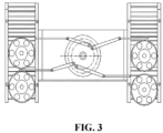
Fig. 3 is a schematic diagram of clockwise rotation of a turntable; and -
Fig. 4 is a schematic diagram of counterclockwise rotation of the turntable. - In the drawings, 1: corner cylinder; 2: rotating shaft; 3: bearing; 4: bearing support; 5: turntable; 6: blocking lever; 6a: first blocking lever; 6b: second blocking lever; 6c: third blocking lever; 6d: fourth blocking lever; 7: first hinge; 8: connection rod; 8a: first connection rod; 8b: second connection rod; 8c: third connection rod; 8d: fourth connection rod; 9: second hinge; 10: wheel; 11: track; 12: track supporting frame; 13: main body bracket; and 14: photoelectric switch.
- The technical solution in the embodiments of the application is clearly and completely described in combination with drawings of the embodiments of the application below, and obviously, the described embodiments are part of embodiments of the application rather than all embodiments.
- The terms 'first', 'second', 'third', 'fourth' and the like in the specification and in the claims of the application are used for distinguishing different objects but not for describing a specific sequence. Furthermore, the terms 'comprise' and 'have' as well as their any variations are intended to cover a non-exclusive inclusion. For example, a process, method, system, product or equipment comprising a series of steps or units does not limit steps or units which have been listed, but selectively further comprises steps or units which are not listed, or selectively further comprises other inherent steps or units for the process, method, product or equipment.
- Reference in the specification to 'embodiments' of the application means that a particular feature, structure or characteristic described in connection with the embodiments is included in at least one embodiment of the application. The appearances of the phrase 'the embodiments' in various places in the specification are not necessarily all referring to the same embodiment, nor are separate or alternative embodiments necessarily mutually exclusive of other embodiments. It will be explicitly and implicitly understood by those skilled in the art that the embodiments described in the application can be combined to other embodiments.
-
Embodiment 1 of the present disclosure is described in combination withFIGs. 1 to 4 . - A temporary storage and separation device for wheels on a track line includes a
main body bracket 13, a rotating mechanism, aturntable 5, a first connection rod 8a, asecond connection rod 8b, athird connection rod 8c, afourth connection rod 8d, afirst blocking lever 6a, asecond blocking lever 6b, athird blocking lever 6c and afourth blocking lever 6d. The rotating mechanism is mounted on themain body bracket 13. The main body bracket is placed on the ground. The upper surface of theturntable 5 is a horizontal plane. Theturntable 5 is connected with the rotating mechanism and may clockwise and counterclockwise rotate with the rotating mechanism. The rotating mechanism includes acorner cylinder 1, a rotating shaft 2, abearing 3 and abearing support 4. Thecorner cylinder 1 is fixed on themain body bracket 13, and an output shaft of thecorner cylinder 1 is fixedly connected with the rotating shaft 2. The rotating shaft 2 is fixedly connected with theturntable 5, and the rotating shaft 2 drives theturntable 5 to rotate. The rotating shaft 2 is disposed in thebearing 3, and thebearing 3 is mounted on thebearing support 4. Thebearing support 4 is fixed on themain body bracket 13. Themain body bracket 13 includes a left side panel, a right side panel, a middle supporting plate and a top panel. The left side panel and the right side panel are respectively fixed on the left and right sides of the middle supporting plate and the top panel. Thecorner cylinder 1 is fixed on the middle supporting plate of themain body bracket 13. Thebearing support 4 is fixed on the middle supporting plate of themain body bracket 13. A circular hole is formed in the middle part of the top panel. Theturntable 5 is disposed in the circular hole formed in the middle part of the top panel. The first connection rod 8a, thesecond connection rod 8b, thethird connection rod 8c and thefourth connection rod 8d are connected to the upper surface of theturntable 5 through first hinges 7, and thefirst blocking lever 6a, thesecond blocking lever 6b, thethird blocking lever 6c and thefourth blocking lever 6d are respectively connected to the first connection rod 8a, thesecond connection rod 8b, thethird connection rod 8c and thefourth connection rod 8d through second hinges 9. Positions, movably connected with the upper surface of the turntable, of the first connection rod 8a and thefourth connection rod 8d are located on a straight line passing through the center of a disc, and positions, movably connected with the upper surface of the turntable, of thesecond connection rod 8b and thethird connection rod 8c are located on another straight line passing through the center of the disc. The position, movably connected with the upper surface of theturntable 5, of the first connection rod 8a and the position, movably connected with the upper surface of theturntable 5, of thethird connection rod 8c are close, and the position, movably connected with the upper surface of theturntable 5, of thesecond connection rod 8b and the position, movably connected with the upper surface of theturntable 5, of thefourth connection rod 8d are close. - The
corner cylinder 1 is a corner cylinder most commonly used by those skilled in the art and capable of rotating by 90 degrees. That is, the corner cylinder may be provided with two target positions forming an included angle of 90 degrees. The rotating mechanism rotates 90 degrees clockwise from the first target position to the second target position, and then rotates 90 degrees counterclockwise from the second target position to the first target position, and the rotating mechanism does a reciprocating motion between the two target positions. When the upper surface of theturntable 5 rotates 90 degrees clockwise with thecorner cylinder 1 from the first target position to the second target position, thefirst blocking lever 6a and thefourth blocking lever 6d are contracted to cause the wheel to move forwards, and thesecond blocking lever 6b and thethird blocking lever 6c are extended to block the wheel. When the upper surface of theturntable 5 rotates 90 degrees counterclockwise with thecorner cylinder 1 from the second target position to the first target position, thesecond blocking lever 6b and thethird blocking lever 6c are contracted to cause the wheel to move forwards, and thefirst blocking lever 6a and thefourth blocking lever 6d are extended to block the wheel. Since the corner cylinder may be manually adjusted in speed and angle of rotation, the separation time or temporary storage time of the temporary storage and separation device for the wheels may be adjusted to adapt to the subsequent production cycles and production efficiency, increase the automation degree of production, reduce the labor intensity of a worker, and stabilize the rhythm of production and improve the production efficiency. - In addition, in some other embodiments, the
corner cylinder 1 may be replaced by a rotary cylinder or a rotary hydraulic cylinder and the same effects can be achieved. - A wheel transfer track line includes the temporary storage and separation device for the wheels on the track line in
Embodiment 1, and also includes tracks and track supporting frames which are located on the left and right sides of themain body bracket 13, a control unit and a plurality ofphotoelectric switches 14 uniformly distributed along the track supporting frames 12. Thetracks 11 are located on the track supporting frames 12. Thefirst blocking lever 6a, thesecond blocking lever 6b, thethird blocking lever 6c and thefourth blocking lever 6d may be extended onto thetracks 11 on the left and right sides of themain body bracket 13 to block the wheel. Reversible motors are disposed in the tracks. Thephotoelectric switches 14 and the reversible motors are all connected with the control unit in a signal manner. - Specific wheel transfer steps on the wheel transfer track line are as follows:
- Step I: as shown in
Fig. 3 , on the wheel transfer track line, thewheel 10 comes from the twotracks 11, and thecorner cylinder 1 acts to drive theturntable 5 to rotate 90 degrees clockwise so as to drive thethird connection rod 8c through the first hinge 7 and thethird blocking lever 6c through the second hinge 9 to be extended out of a slot of themain body bracket 13 and to drive thesecond connection rod 8b through the first hinge 7 and thesecond blocking lever 6b through the second hinge 9 to be extended out of a slot of themain body bracket 13, and so as to drive the first connection rod 8a through the first hinge 7 and thefirst blocking lever 6a through the second hinge 9 to be contracted in a slot of themain body bracket 13 and to drive thefourth connection rod 8d through the first hinge 7 and thefourth blocking lever 6d through the second hinge 9 to be contracted in a slot of themain body bracket 13. In this way, one front wheel on the left track may move forward with the track, and one rear wheel on the left side is blocked by thesecond blocking lever 6b. The blocking lever blocks the wheel on the right track, so that the wheel on the right track is temporarily stored. Meanwhile, the connection rods and the blocking levers also may play a role of separating the front and rear wheels on the same track. - Step II: as shown in
Fig. 4 , then thecorner cylinder 1 acts to drive theturntable 5 to rotate 90 degrees counterclockwise so as to drive the first connection rod 8a through the first hinge 7 and thefirst blocking lever 6a through the second hinge 9 to be extended out of the slot of themain body bracket 13 and to drive thefourth connection rod 8d through the first hinge 7 and thefourth blocking lever 6d through the second hinge 9 to be extended out of the slot of themain body bracket 13, and so as to drive thethird connection rod 8c through the first hinge 7 and thethird blocking lever 6c through the second hinge 9 to be contracted in the slot of themain body bracket 13 and to drive thesecond connection rod 8b through the first hinge 7 and thesecond blocking lever 6b through the second hinge 9 to be contracted in the slot of themain body bracket 13. The front wheel that is previously blocked by thethird blocking lever 6c on the right track may move forwards, and the rear wheel on the right track is blocked by thefourth blocking lever 6d; the previously blocked rear wheel on the left track is blocked by thefirst blocking lever 6a after making one step forward, and the subsequent wheel on the left track is also temporarily stored after making one step forward. Meanwhile, the connection rods and the blocking levers also may play a role of separating the front and rear wheels on the same track. - Step III: on the wheel transfer track line, the
corner cylinder 1 acts to drive theturntable 5 to rotate 90 degrees clockwise, so as to drive thethird connection rod 8c through the first hinge 7 and thethird blocking lever 6c through the second hinge 9 to be extended out of the slot of themain body bracket 13 and to drive thesecond connection rod 8b through the first hinge 7 and thesecond blocking lever 6b through the second hinge 9 to be extended out of the slot of themain body bracket 13, and so as to drive the first connection rod 8a through the first hinge 7 and thefirst blocking lever 6a through the second hinge 9 to be contracted in the slot of themain body bracket 13 and to drive thefourth connection rod 8d through the first hinge 7 and thefourth blocking lever 6d through the second hinge 9 to be contracted in the slot of themain body bracket 13. In this way, one front wheel on the left side of the track may move forwards with the track, and one rear wheel on the left side is blocked by thesecond blocking lever 6b; the previously blocked rear wheel on the right track is blocked by thethird blocking lever 6c after making one step forward, and the subsequent wheel on the right track is also temporarily stored after making one step forward. Meanwhile, the connection rods and the blocking levers also may play a role of separating the front and rear wheels on the same track. Then Step II is continued cyclically. - In addition, the speed and angle of rotation of the corner cylinder may be adjusted according to the requirements of the subsequent production cycles or production efficiency, thereby adjusting the separation time or temporary storage time of the temporary storage and separation device for the wheels to adapt to the subsequent production cycles and production efficiency, increase the automation degree of production, reduce the labor intensity of the worker, and stabilize the rhythm of production and improve the production efficiency.
- In addition, in the present embodiment, the plurality of
photoelectric switches 14 are uniformly distributed along thetrack supporting frames 12, and the reversible motors are disposed in the tracks. Thephotoelectric switches 14 and the reversible motors are all connected with the control unit in a signal manner. The positions of the wheels in the tracks may be determined through thephotoelectric switches 14, thereby ensuring that only one front wheel in the two tracks may move forwards. Thephotoelectric switches 14 cooperate with the control unit to control the reversible motors in the tracks to disperse one front wheel in one track into the other track to realize reversible transfer operation of the wheel. - To summarize, the application provides the temporary storage and separation device for the wheels on the track line; the turntable is used to drive the first blocking lever, the second blocking lever, the third blocking lever and the fourth blocking lever which are disposed at different positions to be extended or contracted to realize separation and temporary storage of the wheels in a transfer process; meanwhile, the photoelectric switches, the reversible motors and the control unit cooperate with the temporary storage and separation device for the wheels to realize reversible transfer on the wheel transfer track line, that is, one front wheel in one track is dispersed into the other track; the temporary storage and separation device for the wheels and the wheel transfer track line may adjust the separation time and temporary storage time to adapt to the subsequent production cycles or production efficiency, increase the automation degree of production, reduce the labor intensity of a worker, and stabilize the rhythm of production and improve the production efficiency.
- The embodiments of the application are described in detail above, particular examples are used herein to explain the principle and embodiments of the application, and the above description of the embodiments is only used to help understanding the methods and core concept of the application.
Claims (8)
- A temporary storage and separation device for wheels on a track line, characterized in that it comprises a main body bracket (13), a rotating mechanism, a turntable (5), a first connection rod (8a), a second connection rod (8b), a third connection rod (8c), a fourth connection rod (8d), a first blocking lever (6a), a second blocking lever (6b), a third blocking lever (6c) and a fourth blocking lever (6d), wherein the rotating mechanism is mounted on the main body bracket (13); an upper surface of the turntable (5) is a horizontal plane; the turntable is connected with the rotating mechanism;the upper surface of the turntable (5) is movably connected with the first connection rod (8a), the second connection rod (8b), the third connection rod (8c) and the fourth connection rod (8d); the first connection rod (8a) is movably connected with the first blocking lever (6a); the second connection (8b) rod is movably connected with the second blocking lever (6b); the third connection rod (8c) is movably connected with the third blocking lever (6c); the fourth connection rod (8d) is movably connected with the fourth blocking lever (6d); positions, movably connected with the upper surface of the turntable, of the first connection rod (8a) and the fourth connection rod (8d) are located on a straight line passing through a center of a disc, and positions, movably connected with the upper surface of the turntable, of the second connection rod (8b) and the third connection rod (8c) are located on another straight line passing through the center of the disc;characterized in that:the turntable (5) is capable of clockwise and counterclockwise rotating with the rotating mechanism; and in thatthe rotating mechanism is capable to be provided with two target positions; the rotating mechanism rotates clockwise from a first target position to a second target position, and then rotates counterclockwise from the second target position to the first target position, and the rotating mechanism does a reciprocating motion between the two target positions; when the upper surface of the turntable (5) rotates clockwise with the rotating mechanism to the first target position, the first blocking lever (6a) and the fourth blocking lever (6d) are contracted to cause the wheel to move forwards, and the second blocking lever (6b) and the third blocking lever (6c) are extended to block the wheel; and when the upper surface of the turntable (5) rotates counterclockwise with the rotating mechanism to the second target position, the second blocking lever (6b) and the third blocking lever (6c) are contracted to cause the wheel to move forwards, and the first blocking lever (6a) and the fourth blocking lever (6d) are extended to block the wheel.
- The temporary storage and separation device for wheels on the track line according to claim 1, characterized in that the rotating mechanism comprises a rotary power component, a rotating shaft (2), a bearing (3) and a bearing support (4); the rotary power component is fixed on the main body bracket (13), and an output shaft of the rotary power component is fixedly connected with the rotating shaft (2); the rotating shaft (2) is fixedly connected with the turntable (5), and the rotating shaft drives the turntable to rotate; the rotating shaft (2) is disposed in the bearing (3); the bearing (3) is mounted on the bearing support (4); and the bearing support (4) is fixed on the main body bracket (13).
- The temporary storage and separation device for wheels on the track line according to claim 2, characterized in that the rotary power component is a corner cylinder (1), a rotary cylinder or a rotary hydraulic cylinder.
- The temporary storage and separation device for wheels on the track line according to claim 1, characterized in that the first connection rod, the second connection rod, the third connection rod and the fourth connection rod are connected to the upper surface of the turntable through first hinges (7), and the first blocking lever, the second blocking lever, the third blocking lever and the fourth blocking lever are respectively connected to the first connection rod, the second connection rod, the third connection rod and the fourth connection rod through second hinges (9).
- The temporary storage and separation device for wheels on the track line according to claim 1, characterized in that a position, movably connected with the upper surface of the turntable (5), of the first connection rod (8a) and a position, movably connected with the upper surface of the turntable (5), of the third connection rod (8c) are close, and a position, movably connected with the upper surface of the turntable (5), of the second connection rod (8b) and a position, movably connected with the upper surface of the turntable (5), of the fourth connection rod (8d) are close.
- The temporary storage and separation device for wheels on the track line according to claim 1, characterized in that the main body bracket (13) comprises a left side panel, a right side panel, a middle supporting plate and a top panel; the left side panel and the right side panel are respectively fixed on left and right sides of the middle supporting plate and the top panel; the rotating mechanism is fixed on the middle supporting plate; a circular hole is formed in a middle part of the top panel; and the turntable (5) is disposed in the circular hole formed in the middle part of the top panel.
- A wheel transfer track line, characterized in that it comprises the temporary storage and separation device for wheels on the track line according to any one of claims 1 to 6, and also comprises tracks (11) and track supporting frames (12) which are located on the left and right sides of the main body bracket (13), wherein the tracks are located on the track supporting frames; and the first blocking lever (6a), the second blocking lever (6b), the third blocking lever (6c) and the fourth blocking lever (6d) may be extended onto the tracks on the left and right sides of the main body bracket (13) to block the wheels (10).
- The wheel transfer track line according to claim 7, also comprising a control unit and a plurality of photoelectric switches (14) uniformly distributed along the track supporting frames (12), wherein reversible motors are disposed in the tracks; and the photoelectric switches and the reversible motors are all connected with the control unit in a signal manner.
Applications Claiming Priority (1)
| Application Number | Priority Date | Filing Date | Title |
|---|---|---|---|
| CN201910117158.XA CN109775334B (en) | 2019-02-15 | 2019-02-15 | Wheel temporary storage separation device on track line and wheel transfer track line |
Publications (2)
| Publication Number | Publication Date |
|---|---|
| EP3696120A1 EP3696120A1 (en) | 2020-08-19 |
| EP3696120B1 true EP3696120B1 (en) | 2023-03-22 |
Family
ID=66504268
Family Applications (1)
| Application Number | Title | Priority Date | Filing Date |
|---|---|---|---|
| EP20154492.1A Active EP3696120B1 (en) | 2019-02-15 | 2020-01-30 | Temporary storage and separation device for wheels on track line and wheel transfer track line |
Country Status (4)
| Country | Link |
|---|---|
| US (1) | US10662005B1 (en) |
| EP (1) | EP3696120B1 (en) |
| CN (1) | CN109775334B (en) |
| MA (1) | MA50378A (en) |
Families Citing this family (7)
| Publication number | Priority date | Publication date | Assignee | Title |
|---|---|---|---|---|
| CN213925547U (en) * | 2020-09-28 | 2021-08-10 | 广州视源电子科技股份有限公司 | Clothes nursing machine |
| CN112520671A (en) * | 2021-01-27 | 2021-03-19 | 无为县翔博生态农业开发有限公司 | A filling equipment for raspberry making wine |
| CN115417132A (en) * | 2022-09-26 | 2022-12-02 | 江西万泰铝业有限公司 | Aluminum bar interval feeding mechanism |
| CN115945569B (en) * | 2023-03-13 | 2023-05-23 | 烟台怡和汽车科技有限公司 | Automobile part punching machine |
| DE102023122552A1 (en) * | 2023-08-23 | 2025-02-27 | Khs Gmbh | Container transport device for transporting containers |
| CN117416724A (en) * | 2023-11-17 | 2024-01-19 | 苏州长光华医生物医学工程有限公司 | A double blocking mechanism and method for releasing continuous products one by one |
| CN118877284B (en) * | 2024-09-30 | 2024-12-27 | 浙江瑞安华联药机科技有限公司 | Carousel suction mechanism |
Family Cites Families (26)
| Publication number | Priority date | Publication date | Assignee | Title |
|---|---|---|---|---|
| US1852034A (en) * | 1931-02-21 | 1932-04-05 | Clara B Parker | Conveyer system |
| US2341705A (en) * | 1941-05-01 | 1944-02-15 | Owens Illinois Glass Co | Indexing mechanism |
| US3850281A (en) * | 1972-04-08 | 1974-11-26 | Focke Pfuhl Verpack Automat | Device for bringing together objects being delivered in two lines |
| JPS54183087U (en) * | 1978-06-15 | 1979-12-25 | ||
| DE3942708A1 (en) * | 1989-12-20 | 1990-06-13 | Robert Kalck | Process for changing direction of flat match boxes - involves chain and entrainment mechanism moving boxes to distributor |
| IT1238300B (en) * | 1990-04-04 | 1993-07-12 | Gd Spa | EQUIPMENT FOR THE TEMPORARY STORAGE OF PRODUCTS. |
| US5165517A (en) * | 1991-09-30 | 1992-11-24 | Noshe Engineering Limited | Combiner for streams of articles, such as bottles |
| US5582283A (en) * | 1994-05-16 | 1996-12-10 | Marel Ltd | Automatic infeeder device |
| US5501522A (en) * | 1994-08-08 | 1996-03-26 | Tung; Lin C. | Multiple rotation materials processor |
| DE50204381D1 (en) * | 2001-10-15 | 2006-02-09 | Ferag Ag | Method and device for the sequential feeding of objects into processing |
| DE102007018532B3 (en) * | 2007-04-19 | 2008-10-16 | Langhammer Maschinenbau Gmbh | Grouping device for transfer of units to roller track has motor-driven rotatable arm above conveyor belt with cross slide on one end and kept parallel to belt by drive |
| US9051129B2 (en) * | 2008-06-23 | 2015-06-09 | Don A. Rogers | Mechanism for improved handling of conveyor packages |
| JP5961523B2 (en) * | 2012-10-16 | 2016-08-02 | 株式会社ファブリカトヤマ | Article separation device |
| JP6308887B2 (en) * | 2014-06-23 | 2018-04-11 | シブヤパッケージングシステム株式会社 | Accumulator |
| CN104358448B (en) * | 2014-10-30 | 2016-08-17 | 王洋 | A kind of cartridge type multi-storied garage Transport Vehicle platform |
| CN205076461U (en) * | 2015-10-30 | 2016-03-09 | 宜宾盈泰光电有限公司 | Be applied to LCD automatic production line's duplex position equipment of keeping in |
| CN109311603B (en) * | 2016-04-07 | 2020-11-24 | 弗莱林克有限公司 | Pallet Handling Equipment |
| CN106743544B (en) * | 2016-12-02 | 2019-08-16 | 亳州易泽信息科技有限公司 | A kind of electric vehicle suspended rack assembly machining feed mechanism |
| CN107324040B (en) * | 2017-07-19 | 2019-04-05 | 新昌县承慧机电设备有限公司 | A kind of single navel orange feeding device |
| CN107444890B (en) * | 2017-09-20 | 2019-05-17 | 浙江大学宁波理工学院 | The charging equipment of braiding machine for thin bamboo strips |
| CN109018960A (en) * | 2017-10-11 | 2018-12-18 | 肇庆市高讯数控设备有限公司 | A kind of auto parts and components machining production line |
| CN107826704A (en) * | 2017-11-30 | 2018-03-23 | 郑佳丹 | A kind of continuous transfer device |
| CN108861542A (en) * | 2018-06-23 | 2018-11-23 | 晋正正 | A kind of axle sleeve continuous and perpendicular lifting mechanism |
| CN109178917A (en) * | 2018-11-02 | 2019-01-11 | 中信戴卡股份有限公司 | A kind of wheel rotation material transfering device |
| CN109205249B (en) * | 2018-11-14 | 2024-05-28 | 江苏省南扬机械制造有限公司 | Strip conveying system |
| CN209567501U (en) * | 2019-02-15 | 2019-11-01 | 中信戴卡股份有限公司 | A wheel temporary storage and separation device on a track line and a wheel transfer track line |
-
2019
- 2019-02-15 CN CN201910117158.XA patent/CN109775334B/en active Active
- 2019-07-26 US US16/523,293 patent/US10662005B1/en active Active
-
2020
- 2020-01-30 EP EP20154492.1A patent/EP3696120B1/en active Active
- 2020-01-30 MA MA050378A patent/MA50378A/en unknown
Also Published As
| Publication number | Publication date |
|---|---|
| US10662005B1 (en) | 2020-05-26 |
| EP3696120A1 (en) | 2020-08-19 |
| CN109775334B (en) | 2023-11-17 |
| CN109775334A (en) | 2019-05-21 |
| MA50378A (en) | 2020-08-19 |
Similar Documents
| Publication | Publication Date | Title |
|---|---|---|
| EP3696120A1 (en) | Temporary storage and separation device for wheels on track line and wheel transfer track line | |
| CN115041764B (en) | Wire cutting system and wire cutting machine | |
| CN113695963A (en) | Angle overturning adjusting control mechanism for plate processing | |
| CN205703292U (en) | A kind of NC rotary table | |
| CN202221735U (en) | Three-position transmission device for isolating and grounding | |
| CN108089599A (en) | A kind of sea radar detection direction-control apparatus and its application method | |
| CN106847611B (en) | Magneto vacuum circuit breaker | |
| CN109095180A (en) | A kind of building board organisation of working | |
| CN103072127B (en) | A type frame rotating device with distributed motive power transmission mechanism | |
| CN209455595U (en) | A kind of guide wheel machine | |
| CN209567501U (en) | A wheel temporary storage and separation device on a track line and a wheel transfer track line | |
| CN205235412U (en) | Be used for shadow show performance device | |
| CN108746395B (en) | Five-axis stamping manipulator | |
| CN214444164U (en) | Welding positioning device for sheet metal parts | |
| KR200437078Y1 (en) | Solar tracking device | |
| CN110979507B (en) | A polar variable area sail robot | |
| CN108942354A (en) | A kind of building environment-friendly sheet organisation of working | |
| CN218170094U (en) | Frame of convenient regulation | |
| CN207104855U (en) | A kind of processing of robots compound motion workbench | |
| CN222474486U (en) | Unmanned aerial vehicle reconnaissance device for improving shooting range | |
| CN221446286U (en) | Laser radar obstacle avoidance detection device | |
| CN213231012U (en) | Pay-off is used in building construction of laying wire | |
| CN221453044U (en) | Supporting device for powder spraying of sound net cover | |
| CN215656454U (en) | Vertical balance wheel sorting machine | |
| CN217947214U (en) | Active wire binding equipment |
Legal Events
| Date | Code | Title | Description |
|---|---|---|---|
| PUAI | Public reference made under article 153(3) epc to a published international application that has entered the european phase |
Free format text: ORIGINAL CODE: 0009012 |
|
| STAA | Information on the status of an ep patent application or granted ep patent |
Free format text: STATUS: REQUEST FOR EXAMINATION WAS MADE |
|
| 17P | Request for examination filed |
Effective date: 20200130 |
|
| AK | Designated contracting states |
Kind code of ref document: A1 Designated state(s): AL AT BE BG CH CY CZ DE DK EE ES FI FR GB GR HR HU IE IS IT LI LT LU LV MC MK MT NL NO PL PT RO RS SE SI SK SM TR |
|
| AX | Request for extension of the european patent |
Extension state: BA ME |
|
| GRAP | Despatch of communication of intention to grant a patent |
Free format text: ORIGINAL CODE: EPIDOSNIGR1 |
|
| STAA | Information on the status of an ep patent application or granted ep patent |
Free format text: STATUS: GRANT OF PATENT IS INTENDED |
|
| INTG | Intention to grant announced |
Effective date: 20221026 |
|
| GRAS | Grant fee paid |
Free format text: ORIGINAL CODE: EPIDOSNIGR3 |
|
| GRAA | (expected) grant |
Free format text: ORIGINAL CODE: 0009210 |
|
| STAA | Information on the status of an ep patent application or granted ep patent |
Free format text: STATUS: THE PATENT HAS BEEN GRANTED |
|
| AK | Designated contracting states |
Kind code of ref document: B1 Designated state(s): AL AT BE BG CH CY CZ DE DK EE ES FI FR GB GR HR HU IE IS IT LI LT LU LV MC MK MT NL NO PL PT RO RS SE SI SK SM TR |
|
| REG | Reference to a national code |
Ref country code: GB Ref legal event code: FG4D |
|
| REG | Reference to a national code |
Ref country code: CH Ref legal event code: EP |
|
| REG | Reference to a national code |
Ref country code: IE Ref legal event code: FG4D |
|
| REG | Reference to a national code |
Ref country code: DE Ref legal event code: R096 Ref document number: 602020008936 Country of ref document: DE |
|
| REG | Reference to a national code |
Ref country code: AT Ref legal event code: REF Ref document number: 1555194 Country of ref document: AT Kind code of ref document: T Effective date: 20230415 |
|
| REG | Reference to a national code |
Ref country code: LT Ref legal event code: MG9D |
|
| REG | Reference to a national code |
Ref country code: NL Ref legal event code: MP Effective date: 20230322 |
|
| PG25 | Lapsed in a contracting state [announced via postgrant information from national office to epo] |
Ref country code: RS Free format text: LAPSE BECAUSE OF FAILURE TO SUBMIT A TRANSLATION OF THE DESCRIPTION OR TO PAY THE FEE WITHIN THE PRESCRIBED TIME-LIMIT Effective date: 20230322 Ref country code: NO Free format text: LAPSE BECAUSE OF FAILURE TO SUBMIT A TRANSLATION OF THE DESCRIPTION OR TO PAY THE FEE WITHIN THE PRESCRIBED TIME-LIMIT Effective date: 20230622 Ref country code: LV Free format text: LAPSE BECAUSE OF FAILURE TO SUBMIT A TRANSLATION OF THE DESCRIPTION OR TO PAY THE FEE WITHIN THE PRESCRIBED TIME-LIMIT Effective date: 20230322 Ref country code: LT Free format text: LAPSE BECAUSE OF FAILURE TO SUBMIT A TRANSLATION OF THE DESCRIPTION OR TO PAY THE FEE WITHIN THE PRESCRIBED TIME-LIMIT Effective date: 20230322 Ref country code: HR Free format text: LAPSE BECAUSE OF FAILURE TO SUBMIT A TRANSLATION OF THE DESCRIPTION OR TO PAY THE FEE WITHIN THE PRESCRIBED TIME-LIMIT Effective date: 20230322 |
|
| REG | Reference to a national code |
Ref country code: AT Ref legal event code: MK05 Ref document number: 1555194 Country of ref document: AT Kind code of ref document: T Effective date: 20230322 |
|
| PG25 | Lapsed in a contracting state [announced via postgrant information from national office to epo] |
Ref country code: SE Free format text: LAPSE BECAUSE OF FAILURE TO SUBMIT A TRANSLATION OF THE DESCRIPTION OR TO PAY THE FEE WITHIN THE PRESCRIBED TIME-LIMIT Effective date: 20230322 Ref country code: NL Free format text: LAPSE BECAUSE OF FAILURE TO SUBMIT A TRANSLATION OF THE DESCRIPTION OR TO PAY THE FEE WITHIN THE PRESCRIBED TIME-LIMIT Effective date: 20230322 Ref country code: GR Free format text: LAPSE BECAUSE OF FAILURE TO SUBMIT A TRANSLATION OF THE DESCRIPTION OR TO PAY THE FEE WITHIN THE PRESCRIBED TIME-LIMIT Effective date: 20230623 Ref country code: FI Free format text: LAPSE BECAUSE OF FAILURE TO SUBMIT A TRANSLATION OF THE DESCRIPTION OR TO PAY THE FEE WITHIN THE PRESCRIBED TIME-LIMIT Effective date: 20230322 |
|
| PG25 | Lapsed in a contracting state [announced via postgrant information from national office to epo] |
Ref country code: SM Free format text: LAPSE BECAUSE OF FAILURE TO SUBMIT A TRANSLATION OF THE DESCRIPTION OR TO PAY THE FEE WITHIN THE PRESCRIBED TIME-LIMIT Effective date: 20230322 Ref country code: RO Free format text: LAPSE BECAUSE OF FAILURE TO SUBMIT A TRANSLATION OF THE DESCRIPTION OR TO PAY THE FEE WITHIN THE PRESCRIBED TIME-LIMIT Effective date: 20230322 Ref country code: PT Free format text: LAPSE BECAUSE OF FAILURE TO SUBMIT A TRANSLATION OF THE DESCRIPTION OR TO PAY THE FEE WITHIN THE PRESCRIBED TIME-LIMIT Effective date: 20230724 Ref country code: ES Free format text: LAPSE BECAUSE OF FAILURE TO SUBMIT A TRANSLATION OF THE DESCRIPTION OR TO PAY THE FEE WITHIN THE PRESCRIBED TIME-LIMIT Effective date: 20230322 Ref country code: EE Free format text: LAPSE BECAUSE OF FAILURE TO SUBMIT A TRANSLATION OF THE DESCRIPTION OR TO PAY THE FEE WITHIN THE PRESCRIBED TIME-LIMIT Effective date: 20230322 Ref country code: AT Free format text: LAPSE BECAUSE OF FAILURE TO SUBMIT A TRANSLATION OF THE DESCRIPTION OR TO PAY THE FEE WITHIN THE PRESCRIBED TIME-LIMIT Effective date: 20230322 |
|
| PG25 | Lapsed in a contracting state [announced via postgrant information from national office to epo] |
Ref country code: SK Free format text: LAPSE BECAUSE OF FAILURE TO SUBMIT A TRANSLATION OF THE DESCRIPTION OR TO PAY THE FEE WITHIN THE PRESCRIBED TIME-LIMIT Effective date: 20230322 Ref country code: PL Free format text: LAPSE BECAUSE OF FAILURE TO SUBMIT A TRANSLATION OF THE DESCRIPTION OR TO PAY THE FEE WITHIN THE PRESCRIBED TIME-LIMIT Effective date: 20230322 Ref country code: IS Free format text: LAPSE BECAUSE OF FAILURE TO SUBMIT A TRANSLATION OF THE DESCRIPTION OR TO PAY THE FEE WITHIN THE PRESCRIBED TIME-LIMIT Effective date: 20230722 |
|
| REG | Reference to a national code |
Ref country code: DE Ref legal event code: R097 Ref document number: 602020008936 Country of ref document: DE |
|
| PLBE | No opposition filed within time limit |
Free format text: ORIGINAL CODE: 0009261 |
|
| STAA | Information on the status of an ep patent application or granted ep patent |
Free format text: STATUS: NO OPPOSITION FILED WITHIN TIME LIMIT |
|
| PG25 | Lapsed in a contracting state [announced via postgrant information from national office to epo] |
Ref country code: SI Free format text: LAPSE BECAUSE OF FAILURE TO SUBMIT A TRANSLATION OF THE DESCRIPTION OR TO PAY THE FEE WITHIN THE PRESCRIBED TIME-LIMIT Effective date: 20230322 Ref country code: DK Free format text: LAPSE BECAUSE OF FAILURE TO SUBMIT A TRANSLATION OF THE DESCRIPTION OR TO PAY THE FEE WITHIN THE PRESCRIBED TIME-LIMIT Effective date: 20230322 Ref country code: CZ Free format text: LAPSE BECAUSE OF FAILURE TO SUBMIT A TRANSLATION OF THE DESCRIPTION OR TO PAY THE FEE WITHIN THE PRESCRIBED TIME-LIMIT Effective date: 20230322 |
|
| 26N | No opposition filed |
Effective date: 20240102 |
|
| PG25 | Lapsed in a contracting state [announced via postgrant information from national office to epo] |
Ref country code: IT Free format text: LAPSE BECAUSE OF FAILURE TO SUBMIT A TRANSLATION OF THE DESCRIPTION OR TO PAY THE FEE WITHIN THE PRESCRIBED TIME-LIMIT Effective date: 20230322 |
|
| PG25 | Lapsed in a contracting state [announced via postgrant information from national office to epo] |
Ref country code: MC Free format text: LAPSE BECAUSE OF FAILURE TO SUBMIT A TRANSLATION OF THE DESCRIPTION OR TO PAY THE FEE WITHIN THE PRESCRIBED TIME-LIMIT Effective date: 20230322 |
|
| PG25 | Lapsed in a contracting state [announced via postgrant information from national office to epo] |
Ref country code: MC Free format text: LAPSE BECAUSE OF FAILURE TO SUBMIT A TRANSLATION OF THE DESCRIPTION OR TO PAY THE FEE WITHIN THE PRESCRIBED TIME-LIMIT Effective date: 20230322 |
|
| REG | Reference to a national code |
Ref country code: CH Ref legal event code: PL |
|
| PG25 | Lapsed in a contracting state [announced via postgrant information from national office to epo] |
Ref country code: LU Free format text: LAPSE BECAUSE OF NON-PAYMENT OF DUE FEES Effective date: 20240130 |
|
| GBPC | Gb: european patent ceased through non-payment of renewal fee |
Effective date: 20240130 |
|
| PG25 | Lapsed in a contracting state [announced via postgrant information from national office to epo] |
Ref country code: LU Free format text: LAPSE BECAUSE OF NON-PAYMENT OF DUE FEES Effective date: 20240130 |
|
| PG25 | Lapsed in a contracting state [announced via postgrant information from national office to epo] |
Ref country code: GB Free format text: LAPSE BECAUSE OF NON-PAYMENT OF DUE FEES Effective date: 20240130 |
|
| PG25 | Lapsed in a contracting state [announced via postgrant information from national office to epo] |
Ref country code: BE Free format text: LAPSE BECAUSE OF NON-PAYMENT OF DUE FEES Effective date: 20240131 |
|
| PG25 | Lapsed in a contracting state [announced via postgrant information from national office to epo] |
Ref country code: CH Free format text: LAPSE BECAUSE OF NON-PAYMENT OF DUE FEES Effective date: 20240131 |
|
| PG25 | Lapsed in a contracting state [announced via postgrant information from national office to epo] |
Ref country code: GB Free format text: LAPSE BECAUSE OF NON-PAYMENT OF DUE FEES Effective date: 20240130 Ref country code: CH Free format text: LAPSE BECAUSE OF NON-PAYMENT OF DUE FEES Effective date: 20240131 Ref country code: BE Free format text: LAPSE BECAUSE OF NON-PAYMENT OF DUE FEES Effective date: 20240131 |
|
| REG | Reference to a national code |
Ref country code: BE Ref legal event code: MM Effective date: 20240131 |
|
| PG25 | Lapsed in a contracting state [announced via postgrant information from national office to epo] |
Ref country code: BG Free format text: LAPSE BECAUSE OF FAILURE TO SUBMIT A TRANSLATION OF THE DESCRIPTION OR TO PAY THE FEE WITHIN THE PRESCRIBED TIME-LIMIT Effective date: 20230322 |
|
| PG25 | Lapsed in a contracting state [announced via postgrant information from national office to epo] |
Ref country code: BG Free format text: LAPSE BECAUSE OF FAILURE TO SUBMIT A TRANSLATION OF THE DESCRIPTION OR TO PAY THE FEE WITHIN THE PRESCRIBED TIME-LIMIT Effective date: 20230322 |
|
| PG25 | Lapsed in a contracting state [announced via postgrant information from national office to epo] |
Ref country code: IE Free format text: LAPSE BECAUSE OF NON-PAYMENT OF DUE FEES Effective date: 20240130 |
|
| PG25 | Lapsed in a contracting state [announced via postgrant information from national office to epo] |
Ref country code: IE Free format text: LAPSE BECAUSE OF NON-PAYMENT OF DUE FEES Effective date: 20240130 |
|
| PG25 | Lapsed in a contracting state [announced via postgrant information from national office to epo] |
Ref country code: CY Free format text: LAPSE BECAUSE OF FAILURE TO SUBMIT A TRANSLATION OF THE DESCRIPTION OR TO PAY THE FEE WITHIN THE PRESCRIBED TIME-LIMIT; INVALID AB INITIO Effective date: 20200130 |
|
| PG25 | Lapsed in a contracting state [announced via postgrant information from national office to epo] |
Ref country code: HU Free format text: LAPSE BECAUSE OF FAILURE TO SUBMIT A TRANSLATION OF THE DESCRIPTION OR TO PAY THE FEE WITHIN THE PRESCRIBED TIME-LIMIT; INVALID AB INITIO Effective date: 20200130 |
|
| VS25 | Lapsed in a validation state [announced via postgrant information from nat. office to epo] |
Ref country code: MA Free format text: FAILURE TO ELECT DOMICILE IN THE NATIONAL COUNTRY Effective date: 20230623 |
|
| PG25 | Lapsed in a contracting state [announced via postgrant information from national office to epo] |
Ref country code: TR Free format text: LAPSE BECAUSE OF FAILURE TO SUBMIT A TRANSLATION OF THE DESCRIPTION OR TO PAY THE FEE WITHIN THE PRESCRIBED TIME-LIMIT Effective date: 20230322 |
|
| PGFP | Annual fee paid to national office [announced via postgrant information from national office to epo] |
Ref country code: DE Payment date: 20260114 Year of fee payment: 7 |
|
| PGFP | Annual fee paid to national office [announced via postgrant information from national office to epo] |
Ref country code: FR Payment date: 20260128 Year of fee payment: 7 |