EP3696033B1 - Bremsvorrichtung - Google Patents
Bremsvorrichtung Download PDFInfo
- Publication number
- EP3696033B1 EP3696033B1 EP19217644.4A EP19217644A EP3696033B1 EP 3696033 B1 EP3696033 B1 EP 3696033B1 EP 19217644 A EP19217644 A EP 19217644A EP 3696033 B1 EP3696033 B1 EP 3696033B1
- Authority
- EP
- European Patent Office
- Prior art keywords
- braking
- movement
- transport position
- braking element
- vehicle
- Prior art date
- Legal status (The legal status is an assumption and is not a legal conclusion. Google has not performed a legal analysis and makes no representation as to the accuracy of the status listed.)
- Active
Links
Images



Classifications
-
- B—PERFORMING OPERATIONS; TRANSPORTING
- B60—VEHICLES IN GENERAL
- B60T—VEHICLE BRAKE CONTROL SYSTEMS OR PARTS THEREOF; BRAKE CONTROL SYSTEMS OR PARTS THEREOF, IN GENERAL; ARRANGEMENT OF BRAKING ELEMENTS ON VEHICLES IN GENERAL; PORTABLE DEVICES FOR PREVENTING UNWANTED MOVEMENT OF VEHICLES; VEHICLE MODIFICATIONS TO FACILITATE COOLING OF BRAKES
- B60T1/00—Arrangements of braking elements, i.e. of those parts where braking effect occurs specially for vehicles
- B60T1/12—Arrangements of braking elements, i.e. of those parts where braking effect occurs specially for vehicles acting otherwise than by retarding wheels, e.g. jet action
- B60T1/14—Arrangements of braking elements, i.e. of those parts where braking effect occurs specially for vehicles acting otherwise than by retarding wheels, e.g. jet action directly on road
-
- B—PERFORMING OPERATIONS; TRANSPORTING
- B60—VEHICLES IN GENERAL
- B60T—VEHICLE BRAKE CONTROL SYSTEMS OR PARTS THEREOF; BRAKE CONTROL SYSTEMS OR PARTS THEREOF, IN GENERAL; ARRANGEMENT OF BRAKING ELEMENTS ON VEHICLES IN GENERAL; PORTABLE DEVICES FOR PREVENTING UNWANTED MOVEMENT OF VEHICLES; VEHICLE MODIFICATIONS TO FACILITATE COOLING OF BRAKES
- B60T1/00—Arrangements of braking elements, i.e. of those parts where braking effect occurs specially for vehicles
- B60T1/005—Arrangements of braking elements, i.e. of those parts where braking effect occurs specially for vehicles by locking of wheel or transmission rotation
-
- F—MECHANICAL ENGINEERING; LIGHTING; HEATING; WEAPONS; BLASTING
- F16—ENGINEERING ELEMENTS AND UNITS; GENERAL MEASURES FOR PRODUCING AND MAINTAINING EFFECTIVE FUNCTIONING OF MACHINES OR INSTALLATIONS; THERMAL INSULATION IN GENERAL
- F16D—COUPLINGS FOR TRANSMITTING ROTATION; CLUTCHES; BRAKES
- F16D63/00—Brakes not otherwise provided for; Brakes combining more than one of the types of groups F16D49/00 - F16D61/00
- F16D63/006—Positive locking brakes
-
- F—MECHANICAL ENGINEERING; LIGHTING; HEATING; WEAPONS; BLASTING
- F16—ENGINEERING ELEMENTS AND UNITS; GENERAL MEASURES FOR PRODUCING AND MAINTAINING EFFECTIVE FUNCTIONING OF MACHINES OR INSTALLATIONS; THERMAL INSULATION IN GENERAL
- F16D—COUPLINGS FOR TRANSMITTING ROTATION; CLUTCHES; BRAKES
- F16D63/00—Brakes not otherwise provided for; Brakes combining more than one of the types of groups F16D49/00 - F16D61/00
- F16D63/008—Brakes acting on a linearly moving member
-
- B—PERFORMING OPERATIONS; TRANSPORTING
- B61—RAILWAYS
- B61H—BRAKES OR OTHER RETARDING DEVICES SPECIALLY ADAPTED FOR RAIL VEHICLES; ARRANGEMENT OR DISPOSITION THEREOF IN RAIL VEHICLES
- B61H7/00—Brakes with braking members co-operating with the track
- B61H7/02—Scotch-blocks, skids, or like track-engaging shoes
- B61H7/04—Scotch-blocks, skids, or like track-engaging shoes attached to railway vehicles
Definitions
- the invention relates to a braking device for a vehicle, having a braking element which is movably connected to a housing and which can be brought from a transport position into a braking position by means of a movement in a first direction of movement, in which a ground can be contacted by the braking element when the braking device is on a Vehicle is arranged.
- the invention relates to a method for braking a vehicle, in particular a tractor, off-road, with a braking device, with a movably connected to a housing braking element, which is brought by a movement in a first movement direction from a transport position to a braking position, in which engages the braking element in a substrate.
- Various braking devices are known in the prior art.
- DE 10 2006 013 967 A1 an additional emergency braking system for automobiles is described.
- a pressure plate is pressed directly against a roadway by a lever/hydraulic system when triggered via a steering wheel or a foot pedal. In the transport position, the pressure plate and a necessary lever or cylinder are arranged so that they can be folded away underneath a vehicle floor.
- this emergency braking system should be used as an additional brake in an emergency, for example in the event of lightning or black ice, in order to reduce the driving speed of the vehicle, specifically in addition to a primary vehicle brake.
- the use of such an emergency braking device has a particularly disadvantageous effect when used on steep terrain, since a braking effect can only be generated by friction and only in one direction of movement of the vehicle, in this case in the direction of travel.
- the document DE 199 36 022A1 describes a brake assembly according to the preamble of claim 1.
- a self-adjusting emergency braking device for motor vehicles is described, with a braking effect being brought about by a braking plate which is brought into direct contact with the ground over its surface.
- the resulting friction between the brake plate and the ground causes a braking effect that reduces the driving speed.
- This emergency braking device also acts in addition to a primary vehicle brake.
- the effect of the emergency brake is given by the frictional resistance of the brake plate and limited to one effective direction. This, in turn, has a negative effect on off-road use. In particular, it is not possible to fix a vehicle in a specific position.
- the object of the invention is to specify a braking device of the type mentioned above, which eliminates the disadvantages of the prior art and makes the braking device usable, for example, on vehicles on steep terrain. At the same time, a simple and inexpensive manufacturability and mountability on the vehicle should be achieved.
- a method for braking a vehicle using a braking device is to be specified.
- the first object is achieved according to the invention in that in a braking device of the type mentioned at least one second braking element is provided, which is movably connected to the housing and can be moved from a transport position to a braking position by means of a movement in a second direction of movement that is different from the first direction of movement .
- An advantage achieved with the invention can be seen in particular in the fact that when at least two braking elements are arranged, which can be moved in different directions from the transport position to the braking position, a braking effect can be achieved in different directions of movement of the vehicle.
- the braking device according to the invention can be used efficiently off-road, especially since a maximum of one braking element can be pushed back in the direction of the transport position counter to the direction of movement due to a movement of the vehicle and contact with the ground, so that an effective braking effect is provided by at least one of the two braking elements.
- a further advantage is a simple design, which enables cost-effective manufacturability and also simple installation on a vehicle.
- the braking device and its components can be designed in different sizes in order to be adapted to different vehicles.
- a spring is expediently connected to the first braking element and/or the second braking element, which spring is relaxed during the movement of the braking element from the transport position into the braking position.
- the braking elements are usually designed in such a way that they can penetrate the ground, in particular a meadow or a forest floor, when the vehicle moves. There is then a braking device in which the braking effect is not only provided by friction, but also by a form fit between the braking elements and the ground. The braking device is then also particularly effective on steep terrain, in which braking devices that only act via friction would fail.
- At least one braking element is at least partially in the form of a plate. This enables the cost-effective and simple design of the brake elements and also saves space when installed underneath the vehicle. In addition, a particularly effective braking effect is achieved with plate-shaped braking elements, especially since there is a large contact surface of the braking device with the ground when plate-shaped braking elements penetrate into the ground, in order to brake the vehicle via the form fit with the ground.
- At least one braking element is designed with a contour tapering to a point at the end and/or two webs, with at least one web having a width of at most 50%, preferably at most 30%, in particular at most 10% of the total width of the braking element. This is how it can be Wedge the brake element into the ground using the webs and then fix it using the tapered contour.
- a holding mechanism for fixing the braking elements in the transport position is expediently provided.
- the braking elements can be fixed in a transport position when they are not required, for example during normal travel of the vehicle.
- the braking elements are usually arranged in such a way that they can be moved from the transport position into the braking position by releasing the holding mechanism.
- the braking elements can then be moved from the transport position to the braking position, for example, with the force of gravity and/or the spring force. It is therefore favorable for the device to be able to be activated quickly if the holding mechanism holds the braking elements in the transport position against a force, in particular against gravity and/or against the spring force, so that the braking elements move into the braking position when the holding mechanism is released by the force be moved.
- the holding mechanism, and thus the braking device can be actuated or activated, for example, by a manually operable switch in a driver's cab of the vehicle on which the braking device is arranged.
- automatic actuation via sensors is also possible, with which impermissible driving states of the vehicle or impermissibly high speeds and/or accelerations are detected.
- the holding mechanism has a bolt for fixing the braking elements in the transport position and a force transmission so that the holding mechanism can be activated and released again with little force, preferably by means of an electromagnet.
- the braking elements can be released from the fixation in the transport position in a simple and rapid manner in order to be brought into the braking position.
- the first braking element can be brought from the transport position into the braking position by means of a movement about a first axis of rotation and the second braking element can be brought from the transport position into the braking position by means of a movement about a second axis of rotation.
- the braking elements can be foldably mounted on an underside of the vehicle, with only a small amount of space being required in the transport position.
- first axis of rotation and the second axis of rotation are approximately parallel and the first braking element and the second braking element can be brought from the transport position into the braking position with opposite rotational movements.
- the braking effect of the braking elements is brought about in opposite directions in each case in order to achieve a reliable braking effect regardless of the movement of the vehicle.
- a stop is provided on at least one braking element, preferably on both braking elements, which limits the movement of the braking element to a movement angle of a maximum of 140°, preferably a maximum of 120°, in particular a maximum of 90° limited, starting from an imaginary plane in which at least one axis of rotation of the first braking element and at least one point of the axis of rotation of the second braking element lie.
- a stop is provided on at least one braking element, preferably on both braking elements, which limits the movement of the braking element to a movement angle of a maximum of 140°, preferably a maximum of 120°, in particular a maximum of 90° limited, starting from an imaginary plane in which at least one axis of rotation of the first braking element and at least one point of the axis of rotation of the second braking element lie.
- a maximum of one of the two braking elements can be pressed counter to the direction of movement, so that this braking element is prevented from penetrating into the ground.
- the second braking element is pushed further in the direction of movement by the movement, when it comes into contact with the ground, until it rests against the stop, so that this braking element can penetrate into the ground in order to brake the vehicle.
- the braking device is designed according to the invention in a vehicle with a braking device. Reliable braking of the vehicle is thereby possible; in particular, a reliable emergency braking function can be ensured by the vehicle equipped with a braking device according to the invention.
- the braking device according to the invention can be used in vehicles of all types, driven and non-driven, in particular in trailers. In particular, the advantages of the braking device according to the invention can be used in the vehicle which is used in steep terrain, in particular in a tractor or the like.
- the braking elements can be rotated about axes of rotation, the axes of rotation being aligned approximately at right angles to a longitudinal axis of the vehicle, which points approximately in the direction of travel. As a result, the vehicle can be braked and fixed reliably.
- the second object is achieved in that, in a method of the type mentioned at the outset, at least a second braking element, which is movably connected to the housing, is brought from a transport position into a braking position by means of a movement in a second direction of movement that differs from the first direction of movement.
- the vehicle can be fixed and braked in different directions of movement.
- the vehicle can be braked and brought back under control, which has slipped on steep terrain and could no longer be braked with a normal vehicle brake.
- FIG. 1 shows a side view of a vehicle 2 with a braking device 1 according to the invention, which is mounted on an underside of the vehicle 2, the vehicle 2 moving in the direction of travel 15 over an uneven surface 7.
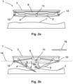
- FIG. 2a shows the braking device 1 according to the invention in a transport position.
- the braking device 1 has a housing 3 for mounting on the vehicle 2, movably connected to the housing braking elements 4, 5, a holding mechanism 11 for fixing the braking elements 4, 5 in the transport position and a spring 8 which is tensioned when the braking elements 4, 5 are in the transport position and is released when the braking elements 4, 5 move from the transport position into a braking position.
- the braking elements 4, 5 are rotatably connected to the housing 3 about parallel axes of rotation 12, 13, with the first braking element 4 being rotatable about a first axis of rotation 12 and the second braking element 5 about a second axis of rotation 13.
- the first braking element 4 is in the opposite direction to the second Braking element 5 can be rotated from the transport position into the braking position, in which the braking element 4 contacts the substrate 7 or penetrates into it in order to brake the vehicle 2 . This ensures that a maximum of one braking element is moved back towards the transport position against the direction of movement when the vehicle 2 moves through the ground 7 and at least one braking element is available for a braking effect.
- Figure 2b shows the braking device 1 according to the invention after activation thereof, with the braking elements 4, 5 being in the braking position.
- the substrate 7 is thereby contacted by the braking elements 4, 5.
- the first braking element 4 has already partially penetrated into the subsurface 7 in order to achieve a strong braking effect through a form fit with the subsurface 7 .
- the vehicle 2, on which the braking device 1 is arranged moves in the direction of travel 15, the first braking element 4, as can be seen, moves away from the transport position in the direction of the braking position through the subsurface 7, and thus further into the subsurface 7, and the second braking element 5 pushed back into the transport position against the direction of movement.
- FIG. 2b shows Figure 2b a movement angle ⁇ , which is the movement of the first braking element 4, starting from an imaginary plane 14 to the deflected braking element 4, wherein in the plane 14 at least a first Axis of rotation 12 of the first braking element 4 and at least one point of a second axis of rotation 13 of the second braking element 5 are described.
- the movement of the braking elements 4, 5 is up to one in Figure 2b stop, not shown, is possible, with a maximum angle of movement then being approximately 110°.
- FIG. 3 shows a top view of the braking device 1 according to the invention.
- Both braking elements 4, 5 in the exemplary embodiment shown here are designed with a contour 9 tapering to a point at the end and two webs 10, with each web 10 as shown having a width of 10% of the total width of an individual braking element . This ensures reliable penetration of the braking element into the subsurface 7 .
- the housing 3 of the braking device 1 according to the invention can also be seen.
- the first braking element 4 can be brought from the transport position into the braking position by means of a movement about the first axis of rotation 12, and the second braking element 5 can be brought from the transport position into the braking position by means of a rotation about the second axis of rotation 13, with the first axis of rotation 12 and the second axis of rotation 13 are approximately parallel and the axes of rotation 12, 13 are aligned approximately at a right angle to a longitudinal axis of the vehicle 2, which points approximately in the direction of travel 15.
- the braking elements 4, 5 can thus be moved from the transport position into the braking position with opposite movements.
- FIG. 4 shows a perspective top view of the braking device 1 according to the invention with the housing 3, with a further embodiment of the spring 8 being shown, and a perspective view of the embodiment of the braking elements 4, 5, with each braking element having the contour 9 tapering to a point at the end and two webs 10 .
- the braking elements 4, 5 are in 4 shown transport position held with the holding mechanism, not shown, which has a bolt with which the first braking element 4 and with this also the second braking element 5 are held in the transport position.
- the holding mechanism for example with an electromagnet
- the bolt can be moved so that it no longer holds the braking elements 4, 5 in the transport position.
- the braking elements 4, 5 are then accelerated about the axes of rotation 12, 13 by gravity in conjunction with a spring force and moved into the braking position in which the braking elements 4, 5 can engage in the ground 7 in order to brake the vehicle 2.
- a braking device With a braking device according to the invention, vehicles that have gotten out of control can be braked easily and reliably, even on steep terrain, and serious accidents can thus be avoided.
- the braking device can be activated, for example, from a driver's cab with an emergency switch or the like.
Landscapes
- Engineering & Computer Science (AREA)
- Mechanical Engineering (AREA)
- General Engineering & Computer Science (AREA)
- Transportation (AREA)
- Braking Arrangements (AREA)
Description
- Die Erfindung betrifft eine Bremsvorrichtung für ein Fahrzeug, aufweisend ein bewegbar mit einem Gehäuse verbundenes Bremselement, welches mittels einer Bewegung in eine erste Bewegungsrichtung aus einer Transportposition in eine Bremsposition bringbar ist, in welcher ein Untergrund durch das Bremselement kontaktierbar ist, wenn die Bremsvorrichtung an einem Fahrzeug angeordnet ist.
- Des Weiteren betrifft die Erfindung ein Verfahren zum Abbremsen eines Fahrzeuges, insbesondere eines Traktors, im Gelände, mit einer Bremsvorrichtung, mit einem bewegbar mit einem Gehäuse verbundenen Bremselement, welches mittels einer Bewegung in eine erste Bewegungsrichtung aus einer Transportposition in eine Bremsposition gebracht wird, in welcher das Bremselement in einen Untergrund eingreift. Gemäß dem Stand der Technik sind verschiedene Bremsvorrichtungen bekannt. Im Dokument
DE 10 2006 013 967 A1 wird ein zusätzliches Notbremssystem für Automobile beschrieben. Dabei wird ein Andruckblech durch ein Hebel-/Hydrauliksystem bei Auslösung über ein Steuerrad oder einen Fußhebel direkt gegen eine Fahrbahn gedrückt. In Transportposition sind das Andruckblech sowie ein erforderlicher Hebel bzw. Zylinder unterhalb eines Fahrzeugbodens wegklappbar angeordnet. Grundsätzlich soll dieses Notbremssystem als Zusatzbremse im Ernstfall verwendet werden, beispielsweise bei Blitz- oder Glatteis, um eine Fahrtgeschwindigkeit des Fahrzeuges zu reduzieren, und zwar ergänzend zu einer primären Fahrzeugbremse. Die Verwendung einer solchen Notbremsvorrichtung wirkt sich besonders während eines Einsatzes im steilen Gelände nachteilig aus, da eine Bremswirkung nur durch Reibung und bloß in eine Fortbewegungsrichtung des Fahrzeuges, in diesem Fall in Fahrtrichtung, generierbar. Das DokumentDE 199 36 022A1 beschreibt eine Bremsanordnung gemäß dem Oberbegriff von Anspruch 1. - Im Dokument
CN 1923582 A wird eine selbstnachstellende Notbremsvorrichtung für Kraftfahrzeuge beschrieben, wobei eine Bremswirkung durch eine Bremsplatte herbeigeführt wird, welche flächig in direkten Kontakt mit dem Untergrund gebracht wird. Die entstehende Reibung zwischen Bremsplatte und Boden bewirkt somit eine die Fahrtgeschwindigkeit reduzierende Bremswirkung. Diese Notbremsvorrichtung wirkt ebenfalls ergänzend zu einer primären Fahrzeugbremse. Auch in diesem Fall ist die Wirkung der Notbremse durch den Reibungswiderstand der Bremsplatte gegeben und begrenzt auf eine Wirkrichtung. Dies wirkt sich wiederum nachteilig für den Einsatz im Gelände aus. Insbesondere ist eine Fixierung eines Fahrzeuges in einer bestimmten Position nicht möglich. So kommt es bei Fahrzeugen, die in steilem Gelände eingesetzt werden, insbesondere Traktoren auf Steilhängen, immer wieder zu Unfällen, welche dadurch zustande kommen, dass ein Fahrer im steilen Gelände eine Kontrolle über das Fahrzeug verliert, das Fahrzeug unkontrolliert beschleunigt und in weiterer Folge abstürzt. Hier versagen die Bremsvorrichtungen des Standes der Technik. - Aufgabe der Erfindung ist es, eine Bremsvorrichtung der eingangs genannten Art anzugeben, welche die Nachteile des Standes der Technik behebt und die Bremsvorrichtung beispielsweise einsetzbar an Fahrzeugen im steilen Gelände macht. Gleichzeitig sollen eine einfache und kostengünstige Herstellbarkeit und Montierbarkeit am Fahrzeug erreicht werden.
- Des Weiteren soll ein Verfahren zum Abbremsen eines Fahrzeuges unter Verwendung einer Bremsvorrichtung angegeben werden.
- Die erste Aufgabe wird erfindungsgemäß dadurch gelöst, dass bei einer Bremsvorrichtung der eingangs erwähnten Art zumindest ein zweites Bremselement vorgesehen ist, welches bewegbar mit dem Gehäuse verbunden und mittels einer Bewegung in einer von der ersten Bewegungsrichtung verschiedenen zweiten Bewegungsrichtung aus einer Transportposition in eine Bremsposition bewegbar ist.
- Ein mit der Erfindung erzielter Vorteil ist insbesondere darin zu sehen, dass bei Anordnung von zumindest zwei Bremselementen, welche in unterschiedliche Bewegungsrichtungen aus der Transportposition in die Bremsposition bewegbar sind, eine Bremswirkung in unterschiedliche Fortbewegungsrichtungen des Fahrzeuges erreichbar ist. Dadurch ist die erfindungsgemäße Bremsvorrichtung im Gelände effizient einsetzbar, zumal durch eine Bewegung des Fahrzeuges und einem Kontakt mit dem Untergrund maximal ein Bremselement entgegen der Bewegungsrichtung wieder in Richtung der Transportposition zurückgedrückt werden kann, sodass eine effektive Bremswirkung zumindest durch eines der beiden Bremselemente gegeben ist. Ein weiterer Vorteil ist eine einfache Bauweise, welche eine kostengünstige Herstellbarkeit und auch eine simple Montage an einem Fahrzeug ermöglicht.
- Die Bremsvorrichtung und deren Bauteile können in verschiedenen Größen ausgebildet sein, um an unterschiedliche Fahrzeuge angepasst zu werden.
- Zweckmäßigerweise ist mit dem ersten Bremselement und/oder dem zweiten Bremselement eine Feder verbunden, welche bei der Bewegung des Bremselements von der Transportposition in die Bremsposition entspannt wird. Dadurch wird die Bewegung der Bremselemente aus der Transportposition in die Bremsposition beschleunigt und mit einer deutlich höheren Kraft durchgeführt, als dies bei einer Verwendung ohne Feder der Fall wäre. Auf diese Weise kann die Bremswirkung effizient innerhalb eines kurzen Zeitraumes erzielt werden. Weiter wird dadurch eine um die Federkraft erhöhte Kraft erreicht, mit welcher die Bremselemente in den Untergrund eindringen können, um das Fahrzeug zügig abzubremsen.
- Üblicherweise sind die Bremselemente derart ausgebildet, dass diese bei einer Bewegung des Fahrzeuges in den Untergrund, insbesondere eine Wiese oder einen Waldboden, eindringen können. Es ist dann eine Bremsvorrichtung gegeben, bei welcher die Bremswirkung nicht nur über Reibung, sondern über einen Formschluss zwischen den Bremselementen und dem Untergrund gegeben ist. Die Bremsvorrichtung ist dann auch insbesondere im steilen Gelände effektiv, in welchem Bremsvorrichtungen, welche nur über die Reibung wirken, versagen würden.
- Es ist von Vorteil, dass zumindest ein Bremselement zumindest teilweise plattenförmig ausgebildet ist. Dies ermöglicht die kostengünstige und einfache Bauweise der Bremselemente und wirkt sich zusätzlich platzsparend bei Montage unterhalb des Fahrzeuges aus. Darüber hinaus wird mit plattenförmigen Bremselementen eine besonders effektive Bremswirkung erreicht, zumal bei einem Eindringen von plattenförmigen Bremselementen in den Untergrund eine große Kontaktfläche der Bremsvorrichtung mit dem Untergrund gegeben ist, um das Fahrzeug über den Formschluss mit dem Untergrund zu bremsen.
- Es hat sich bewährt, dass zumindest ein Bremselement mit einer endseitig spitz zulaufenden Kontur und/oder zwei Stegen ausgebildet ist, wobei zumindest ein Steg eine Breite von maximal 50 %, vorzugsweise maximal 30 %, insbesondere maximal 10 % einer Gesamtbreite des Bremselements aufweist. Auf diese Weise kann sich das Bremselement mit Hilfe der Stege im Untergrund verkeilen und nachfolgend mittels der spitz zulaufenden Kontur fixieren. Somit kann das Fahrzeug im Gelände rasch gebremst werden. Zweckmäßigerweise ist ein Haltemechanismus zur Fixierung der Bremselemente in der Transportposition vorgesehen. Dadurch können die Bremselemente, wenn diese nicht benötigt werden, in einer Transportposition fixiert werden, beispielsweise während einer normalen Fahrt des Fahrzeuges. Üblicherweise sind die Bremselemente derart angeordnet, dass diese von der Transportposition in die Bremsposition bewegbar sind, indem der Haltemechanismus gelöst wird. Die Bremselemente können dann beispielsweise mit einer Schwerkraft und/oder der Federkraft von der Transportposition in die Bremsposition bewegt werden. Günstig ist es daher für eine rasche Aktivierbarkeit der Vorrichtung, wenn der Haltemechanismus die Bremselemente gegen eine Kraft, insbesondere gegen die Schwerkraft und/oder gegen die Federkraft, in der Transportposition hält, sodass die Bremselemente bei einem Lösen des Haltemechanismus durch die Kraft in die Bremsposition bewegt werden. Der Haltemechanismus, und somit die Bremsvorrichtung, kann beispielsweise durch einen manuell betätigbaren Schalter in einer Fahrerkabine des Fahrzeuges, an welchem die Bremsvorrichtung angeordnet ist, betätigt bzw. aktiviert werden. Alternativ ist auch eine automatische Betätigung über Sensoren möglich, mit welchen unzulässige Fahrzustände des Fahrzeuges bzw. unzulässig hohe Geschwindigkeiten und/oder Beschleunigungen erkannt werden.
- Als praktikabel hat es sich herausgestellt, wenn der Haltemechanismus einen Bolzen zur Fixierung der Bremselemente in der Transportposition und eine Kraftübersetzung aufweist, sodass der Haltemechanismus mit geringer Kraft, vorzugsweise mittels eines Elektromagneten, aktivierbar und wieder lösbar ist. Dadurch können die Bremselemente auf einfache und rasche Weise aus der Fixierung in der Transportposition gelöst werden, um in die Bremsposition gebracht zu werden.
- Es ist von Vorteil, dass das erste Bremselement mittels einer Bewegung um eine erste Drehachse von der Transportposition in die Bremsposition bringbar ist und das zweite Bremselement mittels einer Bewegung um eine zweite Drehachse von der Transportposition in die Bremsposition bringbar ist. Dadurch sind die Bremselemente klappbar an einer Unterseite des Fahrzeuges montierbar, wobei in der Transportposition nur ein geringer Platzbedarf gegeben ist.
- Es hat sich bewährt, dass die erste Drehachse und die zweite Drehachse etwa parallel sind und das erste Bremselement und das zweite Bremselement mit gegenläufiger Drehbewegung von der Transportposition in die Bremsposition bringbar sind. Dadurch wird die Bremswirkung der Bremselemente in jeweils entgegengesetzte Richtung hervorgerufen, um eine zuverlässige Bremswirkung unabhängig von der Bewegung des Fahrzeuges zu erreichen.
- Um eine besonders zuverlässige Bremswirkung zu erreichen, ist es günstig, wenn zumindest an einem Bremselement, vorzugsweise an beiden Bremselementen, ein Anschlag vorgesehen ist, welcher die Bewegung des Bremselements auf einen Bewegungswinkel von maximal 140°, vorzugsweise maximal 120°, insbesondere maximal 90° begrenzt, ausgehend von einer gedachten Ebene, in der zumindest eine Drehachse des ersten Bremselements und zumindest ein Punkt der Drehachse des zweiten Bremselements liegen. Es ist dann in Verbindung mit den unterschiedlichen Bewegungsrichtungen, mittels welcher die Bremselemente von der Transportposition in die Bremsposition bewegt werden, sichergestellt, dass die Bremswirkung durch das Eindringen zumindest eines Bremselements in den Untergrund gegeben ist, und zwar unabhängig davon, in welche Richtung sich das abzubremsende Fahrzeug bewegt. So kann durch die Bewegung maximal eines der beiden Bremselemente entgegen der Bewegungsrichtung gedrückt werden, sodass das Eindringen dieses Bremselements in den Untergrund verhindert ist. Das zweite Bremselement wird jedoch durch die Bewegung, bei Kontakt mit dem Untergrund, weiter in Bewegungsrichtung gedrückt, bis dieses am Anschlag anliegt, sodass dieses Bremselement in den Untergrund eindringen kann, um das Fahrzeug zu bremsen.
- Günstig ist es, wenn bei einem Fahrzeug mit einer Bremsvorrichtung die Bremsvorrichtung erfindungsgemäß ausgebildet ist. Dadurch ist ein zuverlässiges Bremsen des Fahrzeuges möglich, insbesondere kann durch das mit einer erfindungsgemäßen Bremsvorrichtung ausgestattete Fahrzeug eine zuverlässige Notbremsfunktion gewährleistet werden. Die erfindungsgemäße Bremsvorrichtung kann bei Fahrzeugen aller Art, angetriebenen und nichtangetriebenen, insbesondere bei Anhängern, eingesetzt werden. Besonders können die Vorteile der erfindungsgemäßen Bremsvorrichtung beim Fahrzeug genutzt werden, welches im steilen Gelände eingesetzt wird, insbesondere bei einem Traktor oder dergleichen.
- Es hat sich bewährt, dass die Bremselemente um Drehachsen drehbar sind, wobei die Drehachsen etwa in einem rechten Winkel auf eine Längsachse des Fahrzeuges, welche etwa in Fahrtrichtung weist, ausgerichtet sind. Dadurch ist das Fahrzeug zuverlässig abbremsbar und fixierbar.
- Die zweite Aufgabe wird dadurch gelöst, dass bei einem Verfahren der eingangs genannten Art zumindest ein zweites, bewegbar mit dem Gehäuse verbundenes Bremselement mittels einer Bewegung in einer von der ersten Bewegungsrichtung verschiedenen zweiten Bewegungsrichtung aus einer Transportposition in eine Bremsposition gebracht wird. Dadurch ist das Fahrzeug in unterschiedliche Fortbewegungsrichtungen fixierbar und bremsbar. Somit kann beispielsweise das Fahrzeug gebremst und wieder unter Kontrolle gebracht werden, welches im steilen Gelände abgerutscht ist und mit einer normalen Fahrzeugbremse nicht mehr bremsbar wäre.
- Weitere Merkmale, Vorteile und Wirkungen der Erfindung ergeben sich anhand der nachfolgend dargestellten Ausführungsbeispiele. In den Zeichnungen, auf welche dabei Bezug genommen wird, zeigen:
-
Fig. 1 eine erfindungsgemäße Bremsvorrichtung in einer Seitenansicht montiert an einem Fahrzeug; -
Fig. 2a die erfindungsgemäße Bremsvorrichtung in einer Transportposition; -
Fig. 2b die erfindungsgemäße Bremsvorrichtung in einer Bremsposition; -
Fig. 3 eine Draufsicht auf die erfindungsgemäße Bremsvorrichtung; -
Fig. 4 eine perspektivische Draufsicht auf die erfindungsgemäße Bremsvorrichtung. -
Fig. 1 zeigt eine Seitenansicht eines Fahrzeuges 2 mit einer erfindungsgemäßen Bremsvorrichtung 1, welche an einer Unterseite des Fahrzeuges 2 montiert ist, wobei sich das Fahrzeug 2 in Fahrtrichtung 15 über einen unebenen Untergrund 7 fortbewegt. -
Fig. 2a zeigt die erfindungsgemäße Bremsvorrichtung 1 in einer Transportposition. Wie ersichtlich weist die Bremsvorrichtung 1 ein Gehäuse 3 zur Montage am Fahrzeug 2, bewegbar mit dem Gehäuse verbundene Bremselemente 4, 5, einen Haltemechanismus 11 zur Fixierung der Bremselemente 4, 5 in der Transportposition und eine Feder 8 auf, welche gespannt ist, wenn sich die Bremselemente 4, 5 in der Transportposition befinden und bei einer Bewegung der Bremselemente 4, 5 von der Transportposition in eine Bremsposition entspannt wird. Die Bremselemente 4, 5 sind um parallele Drehachsen 12, 13 drehbar mit dem Gehäuse 3 verbunden, wobei das erste Bremselement 4 um eine erste Drehachse 12 drehbar ist und das zweite Bremselement 5 um eine zweite Drehachse 13. Das erste Bremselement 4 ist gegenläufig zum zweiten Bremselement 5 aus der Transportposition in die Bremsposition drehbar, in welcher das Bremselement 4 den Untergrund 7 kontaktiert bzw. in diesen eindringt, um das Fahrzeug 2 zu bremsen. Dadurch ist sichergestellt, dass maximal ein Bremselement bei einer Bewegung des Fahrzeuges 2 durch den Untergrund 7 entgegen der Bewegungsrichtung zurück in Richtung der Transportposition bewegt wird und zumindest ein Bremselement für eine Bremswirkung verfügbar ist. - In
Fig. 2a ist das Fahrzeug 2, an welchem die Bremsvorrichtung 1 angeordnet ist, nicht mehr dargestellt. Wie ersichtlich befindet sich die Bremsvorrichtung 1 in einem gewissen Abstand zum Untergrund 7, wobei dieser Abstand durch eine Unterbodenhöhe des Fahrzeuges 2 definiert ist. -
Fig. 2b zeigt die erfindungsgemäße Bremsvorrichtung 1 nach einer Aktivierung derselben, wobei sich die Bremselemente 4, 5 in der Bremsposition befinden. Dabei wird der Untergrund 7 durch die Bremselemente 4, 5 kontaktiert. Das erste Bremselement 4 ist bereits teilweise in den Untergrund 7 eingedrungen, um durch einen Formschluss mit dem Untergrund 7 eine starke Bremswirkung zu erreichen. Bei der Bewegung des Fahrzeuges 2, an welchem die Bremsvorrichtung 1 angeordnet ist, in Fahrtrichtung 15 wird das erste Bremselement 4 wie ersichtlich durch den Untergrund 7 von der Transportposition weg in Richtung der Bremsposition, und somit weiter in den Untergrund 7, und das zweite Bremselement 5 entgegen der Bewegungsrichtung in die Transportposition zurückgedrückt. Dadurch wird ein Eindringen des ersten Bremselements 4 in den Untergrund 7 erreicht, selbst wenn das zweite Bremselement 5 nicht in den Untergrund 7 eindringt und nur eine eingeschränkte Bremswirkung entfalten kann. Dadurch kann ein außer Kontrolle geratenes Fahrzeug 2 auch im steilen Gelände zuverlässig wieder unter Kontrolle gebracht werden. Überdies zeigtFig. 2b einen Bewegungswinkel α, welcher die Bewegung des ersten Bremselements 4, ausgehend von einer gedachten Ebene 14 bis zum ausgelenkten Bremselement 4, wobei in der Ebene 14 zumindest eine erste Drehachse 12 des ersten Bremselements 4 und zumindest ein Punkt einer zweiten Drehachse 13 des zweiten Bremselements 5 liegen, beschreibt. Die Bewegung der Bremselemente 4, 5 ist bis zu einem inFig. 2b nicht dargestellten Anschlag möglich, wobei ein maximaler Bewegungswinkel dann etwa 110° beträgt. - Weiter ist ersichtlich, dass in der in
Fig. 2b dargestellten Position der Bremselemente 4, 5 die Feder 8 gegenüber der inFig. 2a dargestellten Position entspannt ist. Die Feder 8 verstärkt somit die Bremswirkung bzw. bewirkt eine rasche Bewegung der Bremselemente 4, 5 von der jeweiligen Transportposition in die jeweilige Bremsposition und unterstützt das Eindringen der Bremselemente 4, 5 in den Untergrund 7. -
Fig. 3 zeigt eine Draufsicht der erfindungsgemäßen Bremsvorrichtung 1. Beide Bremselemente 4, 5 sind bei dem hier dargestellten Ausführungsbeispiel mit einer endseitig spitz zulaufenden Kontur 9 und zwei Stegen 10 ausgebildet, wobei jeder Steg 10 wie dargestellt eine Breite von 10 % einer Gesamtbreite eines einzelnen Bremselements aufweisen kann. Dadurch ist ein zuverlässiges Eindringen des Bremselements in den Untergrund 7 gewährleistet. Ferner ist das Gehäuse 3 der erfindungsgemäßen Bremsvorrichtung 1 ersichtlich. Darüber hinaus zeigtFig. 3 ein mögliches Ausführungsbeispiel der Feder 8, welche die Bremselemente 4, 5 verbindet. Das erste Bremselement 4 ist mittels einer Bewegung um die erste Drehachse 12 von der Transportposition in die Bremsposition bringbar und das zweite Bremselement 5 mittels einer Drehung um die zweite Drehachse 13 von der Transportposition in die Bremsposition bringbar, wobei die erste Drehachse 12 und die zweite Drehachse 13 etwa parallel sind und die Drehachsen 12, 13 etwa in einem rechten Winkel auf eine Längsachse des Fahrzeuges 2, welche etwa in Fahrtrichtung 15 weist, ausgerichtet sind. Die Bremselemente 4, 5 sind somit mit gegenläufigen Bewegungen aus der Transportposition in die Bremsposition bringbar. -
Fig. 4 zeigt eine perspektivische Draufsicht auf die erfindungsgemäße Bremsvorrichtung 1 mit dem Gehäuse 3, wobei ein weiteres Ausführungsbeispiel der Feder 8 gezeigt wird, und eine perspektivische Ansicht des Ausführungsbeispiels der Bremselemente 4, 5, wobei jedes Bremselement die endseitig spitz zulaufende Kontur 9 und zwei Stege 10 aufweist. - Die Bremselemente 4, 5 werden in der in
Fig. 4 dargestellten Transportposition mit dem nicht dargestellten Haltemechanismus gehalten, welcher einen Bolzen aufweist, mit welchem das erste Bremselement 4 und mit diesem auch das zweite Bremselement 5 in der Transportposition gehalten werden. Durch ein Betätigen des Haltemechanismus, beispielsweise mit einem Elektromagneten, kann der Bolzen bewegt werden, sodass dieser die Bremselemente 4, 5 nicht mehr in der Transportposition hält. Die Bremselemente 4, 5 werden dann durch eine Schwerkraft in Verbindung mit einer Federkraft um die Drehachsen 12, 13 beschleunigt und in die Bremsposition bewegt, in welcher die Bremselemente 4, 5 in den Untergrund 7 eingreifen können, um das Fahrzeug 2 zu bremsen. - Mit einer erfindungsgemäßen Bremseinrichtung können außer Kontrolle geratene Fahrzeuge auch im steilen Gelände einfach und zuverlässig abgebremst und somit schwere Unfälle vermieden werden. Die Bremsvorrichtung kann beispielsweise von einer Fahrerkabine aus mit einem Notschalter oder dergleichen aktiviert werden.
Claims (10)
- Bremsvorrichtung (1) für ein Fahrzeug (2), aufweisend ein bewegbar mit einem Gehäuse (3) verbundenes Bremselement (4), welches mittels einer Bewegung in eine erste Bewegungsrichtung (6a) aus einer Transportposition in eine Bremsposition bringbar ist, in welcher ein Untergrund (7) durch das Bremselement (4) kontaktierbar ist, wenn die Bremsvorrichtung (1) an einem Fahrzeug (2) angeordnet ist, wobei zumindest ein zweites Bremselement (5) vorgesehen ist, welches bewegbar mit dem Gehäuse (3) verbunden und mittels einer Bewegung in einer von der ersten Bewegungsrichtung (6a) verschiedenen zweiten Bewegungsrichtung (6b) aus einer Transportposition in eine Bremsposition bewegbar ist, dadurch gekennzeichnet, dass ein Haltemechanismus (11) zur Fixierung der Bremselemente (4, 5) in der Transportposition vorgesehen ist, wobei der Haltemechanismus (11) einen Bolzen zur Fixierung der Bremselemente (4, 5) in der Transportposition und eine Kraftübersetzung aufweist, sodass der Haltemechanismus (11) mit geringer Kraft, vorzugsweise mittels eines Elektromagneten, aktivierbar und wieder lösbar ist.
- Bremsvorrichtung (1) nach Anspruch 1, dadurch gekennzeichnet, dass mit dem ersten Bremselement (4) und/oder dem zweiten Bremselement (5) eine Feder (8) verbunden ist, welche bei Bewegung des ersten Bremselements (4) und/oder zweiten Bremselements (5) von der Transportposition in die Bremsposition entspannt wird.
- Bremsvorrichtung (1) nach Anspruch 1 oder 2, dadurch gekennzeichnet, dass zumindest ein Bremselement zumindest teilweise plattenförmig ausgebildet ist.
- Bremsvorrichtung (1) nach Anspruch 3, dadurch gekennzeichnet, dass zumindest ein Bremselement mit einer endseitig spitz zulaufenden Kontur (9) und/oder zwei Stegen (10) ausgebildet ist, wobei zumindest ein Steg (10) eine Breite von maximal 50 %, vorzugsweise maximal 30 %, insbesondere maximal 10 % einer Gesamtbreite des Bremselements aufweist.
- Bremsvorrichtung (1) nach einem der Ansprüche 1 bis 4, dadurch gekennzeichnet, dass das erste Bremselement (4) mittels einer Bewegung um eine erste Drehachse (12) von der Transportposition in die Bremsposition und das zweite Bremselement (5) mittels einer Bewegung um eine zweite Drehachse (13) von der Transportposition in die Bremsposition bringbar ist.
- Bremsvorrichtung (1) nach Anspruch 5, dadurch gekennzeichnet, dass die erste Drehachse (12) und die zweite Drehachse (13) etwa parallel sind und das erste Bremselement (4) und das zweite Bremselement (5) mittels gegenläufiger Drehbewegungen von der Transportposition in die Bremsposition bringbar sind.
- Bremsvorrichtung (1) nach einem der Ansprüche 1 bis 6, dadurch gekennzeichnet, dass an zumindest einem Bremselement, vorzugsweise an beiden Bremselementen (4, 5), ein Anschlag vorgesehen ist, welcher die Bewegung des Bremselements auf einen Bewegungswinkel (α) von maximal 140°, vorzugsweise maximal 120°, insbesondere maximal 90° begrenzt, ausgehend von einer gedachten Ebene (14), in der zumindest eine Drehachse des ersten Bremselements (4) und zumindest ein Punkt einer Drehachse des zweiten Bremselements (5) liegen.
- Fahrzeug (2) mit einer Bremsvorrichtung (1), dadurch gekennzeichnet, dass die Bremsvorrichtung (1) nach einem der Ansprüche 1 bis 7 ausgebildet ist.
- Fahrzeug (2) nach Anspruch 8, dadurch gekennzeichnet, dass die Bremselemente (4, 5) um Drehachsen (12, 13) drehbar sind, wobei die Drehachsen (12, 13) etwa in einem rechten Winkel auf eine Längsachse des Fahrzeuges (2), welche etwa in Fahrtrichtung (15) weist, ausgerichtet sind.
- Verfahren zum Abbremsen eines Fahrzeuges (2), insbesondere eines Traktors, im Gelände mit einer Bremsvorrichtung (1), insbesondere einer Bremsvorrichtung (1) nach einem der Ansprüche 1 bis 7, mit einem bewegbar mit einem Gehäuse (3) verbundenen Bremselement (4), welches mittels einer Bewegung in eine erste Bewegungsrichtung (6a) aus einer Transportposition in eine Bremsposition gebracht wird, in welcher das Bremselement (4) in einen Untergrund (7) eingreift, wobei zumindest ein zweites, bewegbar mit dem Gehäuse (3) verbundenes Bremselement (5) mittels einer Bewegung in einer von der ersten Bewegungsrichtung (6a) verschiedenen zweiten Bewegungsrichtung (6b) aus einer Transportposition in eine Bremsposition gebracht wird, dadurch gekennzeichnet, dass die Bremselemente (4, 5) in der Transportposition mit einem Haltemechanismus (11) gehalten werden, wobei der Haltemechanismus (11) einen Bolzen aufweist, mit welchem das erste Bremselement (4) und mit diesem auch das zweite Bremselement (5) in der Transportposition gehalten werden, wobei der Haltemechanismus (11), beispielsweise mit einem Elektromagneten, betätigt wird, wobei der Bolzen bewegt wird, sodass dieser die Bremselemente (4, 5) nicht mehr in der Transportposition hält.
Applications Claiming Priority (1)
| Application Number | Priority Date | Filing Date | Title |
|---|---|---|---|
| ATA50118/2019A AT522197B1 (de) | 2019-02-18 | 2019-02-18 | Bremsvorrichtung |
Publications (2)
| Publication Number | Publication Date |
|---|---|
| EP3696033A1 EP3696033A1 (de) | 2020-08-19 |
| EP3696033B1 true EP3696033B1 (de) | 2023-04-12 |
Family
ID=68965679
Family Applications (1)
| Application Number | Title | Priority Date | Filing Date |
|---|---|---|---|
| EP19217644.4A Active EP3696033B1 (de) | 2019-02-18 | 2019-12-18 | Bremsvorrichtung |
Country Status (2)
| Country | Link |
|---|---|
| EP (1) | EP3696033B1 (de) |
| AT (1) | AT522197B1 (de) |
Family Cites Families (10)
| Publication number | Priority date | Publication date | Assignee | Title |
|---|---|---|---|---|
| US1334644A (en) * | 1919-05-05 | 1920-03-23 | Atherton Joseph | Antiskidding device for vehicles |
| GB250458A (en) * | 1925-08-27 | 1926-04-15 | Walter Moore | An emergency stopping device for motor and other vehicles |
| US3113641A (en) * | 1959-11-20 | 1963-12-10 | Auxiliaire De L Entpr Soc | Arrangement of lateral spades for an earthmoving appliance mounted on pneumatic tires |
| DE2641803A1 (de) * | 1976-09-17 | 1978-03-23 | Lermer App Gmbh | Stopp- und verriegelungseinrichtung fuer ein fahr- bzw. rollbares, insbesondere im bereich der luftfahrt in flugzeugen verwendbares behaeltnis |
| US4613015A (en) * | 1984-06-22 | 1986-09-23 | Skrzypek James R | Self energizing emergency brake and anti-side-skid apparatus |
| WO1994003350A1 (en) * | 1992-08-08 | 1994-02-17 | Joo Hee Lee | Auxiliary brake system for automobile |
| DE19936022A1 (de) * | 1999-08-04 | 2001-05-03 | Loebl Jean Pierre | Verfahren und Vorrichtung zum Notbremsen von Rennfahrzeugen |
| DE102006013967A1 (de) | 2006-03-27 | 2007-10-11 | Paul Vierling | Zusätzliche Notbremse für Automobile |
| CN100532169C (zh) | 2006-09-05 | 2009-08-26 | 翁中飞 | 汽车自调整紧急制动装置 |
| DE102012021019B4 (de) * | 2012-10-26 | 2019-06-19 | Audi Ag | Notbremsvorrichtung für ein Fahrzeug und Verfahren zur Notbremsung eines Fahrzeugs |
-
2019
- 2019-02-18 AT ATA50118/2019A patent/AT522197B1/de active
- 2019-12-18 EP EP19217644.4A patent/EP3696033B1/de active Active
Also Published As
| Publication number | Publication date |
|---|---|
| AT522197A1 (de) | 2020-09-15 |
| AT522197B1 (de) | 2020-11-15 |
| EP3696033A1 (de) | 2020-08-19 |
Similar Documents
| Publication | Publication Date | Title |
|---|---|---|
| DE69804260T2 (de) | Bremspedalanordnung für ein Kraftfahrzeug | |
| DE102016214956B4 (de) | Fahrzeugpedalvorrichtung | |
| DE69711848T2 (de) | Vorrichtung und verfahren zum auslösen einer sicherheitsvorrichtung in einem fahrzeug | |
| EP1343662A1 (de) | Vorrichtung zur lagerung eines pedalhebels eines kraftfahrzeuges | |
| DE60308806T2 (de) | Pedalanordnung | |
| WO2007101565A1 (de) | Lenksäulenanordnung für fahrzeuge | |
| DE1020531B (de) | Fusshebel fuer Kraftfahrzeuge | |
| DE3904837A1 (de) | Betaetigungseinrichtung fuer eine kraftfahrzeugkupplung | |
| DE2818372C2 (de) | ||
| DE10028117A1 (de) | Pedalhalterungskonstruktion | |
| AT522197B1 (de) | Bremsvorrichtung | |
| DE102019206487A1 (de) | Verfahren und Vorrichtung zum Betreiben eines Feststellbremssystems | |
| DE102012021019B4 (de) | Notbremsvorrichtung für ein Fahrzeug und Verfahren zur Notbremsung eines Fahrzeugs | |
| DE102005042281A1 (de) | Fußhebelwerkanordnung für ein Kraftfahrzeug | |
| EP1272377A1 (de) | Crash-sichere pedalerie in einem fahrzeug | |
| DE4337225A1 (de) | Aktiver Frontstoßfänger für Kraftfahrzeuge, der zu seiner Aktivierung die bei einem Bremsvorgang wirkenden Verzögerungskräfte nutzt | |
| DE2940836C2 (de) | ||
| DE102018007392B4 (de) | Lenksäule mit einer steuervorrichtung für ein fahrzeug und fahrzeug mit einer derartigen lenksäule | |
| DE10207006A1 (de) | Vorrichtung zum Öffnen einer Lagerung | |
| WO1998016404A1 (de) | Rastvorrichtung für crashsichere betätigungseinrichtung insbesondere von bremsensystemen | |
| EP3366509B1 (de) | Schienenanordnung für einen längseinsteller und fahrzeugsitz | |
| DE2106664B2 (de) | Auflaufbremsanlage fuer anhaenger | |
| DE102013010284B4 (de) | Pedaleinheit für ein Fahrzeug, insbesondere Kraftfahrzeug | |
| DE102019215175B3 (de) | Verfahren und Vorrichtung zur Erhöhung einer Reifenhaftung eines Fahrzeugs | |
| EP1637421B1 (de) | Bremsenbetätigungseinrichtung für ein Kraftfahrzeug |
Legal Events
| Date | Code | Title | Description |
|---|---|---|---|
| PUAI | Public reference made under article 153(3) epc to a published international application that has entered the european phase |
Free format text: ORIGINAL CODE: 0009012 |
|
| STAA | Information on the status of an ep patent application or granted ep patent |
Free format text: STATUS: THE APPLICATION HAS BEEN PUBLISHED |
|
| AK | Designated contracting states |
Kind code of ref document: A1 Designated state(s): AL AT BE BG CH CY CZ DE DK EE ES FI FR GB GR HR HU IE IS IT LI LT LU LV MC MK MT NL NO PL PT RO RS SE SI SK SM TR |
|
| AX | Request for extension of the european patent |
Extension state: BA ME |
|
| STAA | Information on the status of an ep patent application or granted ep patent |
Free format text: STATUS: REQUEST FOR EXAMINATION WAS MADE |
|
| 17P | Request for examination filed |
Effective date: 20210218 |
|
| RBV | Designated contracting states (corrected) |
Designated state(s): AL AT BE BG CH CY CZ DE DK EE ES FI FR GB GR HR HU IE IS IT LI LT LU LV MC MK MT NL NO PL PT RO RS SE SI SK SM TR |
|
| GRAP | Despatch of communication of intention to grant a patent |
Free format text: ORIGINAL CODE: EPIDOSNIGR1 |
|
| STAA | Information on the status of an ep patent application or granted ep patent |
Free format text: STATUS: GRANT OF PATENT IS INTENDED |
|
| INTG | Intention to grant announced |
Effective date: 20221215 |
|
| GRAS | Grant fee paid |
Free format text: ORIGINAL CODE: EPIDOSNIGR3 |
|
| GRAA | (expected) grant |
Free format text: ORIGINAL CODE: 0009210 |
|
| STAA | Information on the status of an ep patent application or granted ep patent |
Free format text: STATUS: THE PATENT HAS BEEN GRANTED |
|
| AK | Designated contracting states |
Kind code of ref document: B1 Designated state(s): AL AT BE BG CH CY CZ DE DK EE ES FI FR GB GR HR HU IE IS IT LI LT LU LV MC MK MT NL NO PL PT RO RS SE SI SK SM TR |
|
| REG | Reference to a national code |
Ref country code: GB Ref legal event code: FG4D Free format text: NOT ENGLISH |
|
| REG | Reference to a national code |
Ref country code: CH Ref legal event code: EP |
|
| REG | Reference to a national code |
Ref country code: DE Ref legal event code: R096 Ref document number: 502019007434 Country of ref document: DE |
|
| REG | Reference to a national code |
Ref country code: IE Ref legal event code: FG4D Free format text: LANGUAGE OF EP DOCUMENT: GERMAN |
|
| REG | Reference to a national code |
Ref country code: AT Ref legal event code: REF Ref document number: 1559611 Country of ref document: AT Kind code of ref document: T Effective date: 20230515 |
|
| REG | Reference to a national code |
Ref country code: LT Ref legal event code: MG9D |
|
| REG | Reference to a national code |
Ref country code: NL Ref legal event code: MP Effective date: 20230412 |
|
| PG25 | Lapsed in a contracting state [announced via postgrant information from national office to epo] |
Ref country code: NL Free format text: LAPSE BECAUSE OF FAILURE TO SUBMIT A TRANSLATION OF THE DESCRIPTION OR TO PAY THE FEE WITHIN THE PRESCRIBED TIME-LIMIT Effective date: 20230412 |
|
| PG25 | Lapsed in a contracting state [announced via postgrant information from national office to epo] |
Ref country code: SE Free format text: LAPSE BECAUSE OF FAILURE TO SUBMIT A TRANSLATION OF THE DESCRIPTION OR TO PAY THE FEE WITHIN THE PRESCRIBED TIME-LIMIT Effective date: 20230412 Ref country code: PT Free format text: LAPSE BECAUSE OF FAILURE TO SUBMIT A TRANSLATION OF THE DESCRIPTION OR TO PAY THE FEE WITHIN THE PRESCRIBED TIME-LIMIT Effective date: 20230814 Ref country code: NO Free format text: LAPSE BECAUSE OF FAILURE TO SUBMIT A TRANSLATION OF THE DESCRIPTION OR TO PAY THE FEE WITHIN THE PRESCRIBED TIME-LIMIT Effective date: 20230712 Ref country code: ES Free format text: LAPSE BECAUSE OF FAILURE TO SUBMIT A TRANSLATION OF THE DESCRIPTION OR TO PAY THE FEE WITHIN THE PRESCRIBED TIME-LIMIT Effective date: 20230412 |
|
| PG25 | Lapsed in a contracting state [announced via postgrant information from national office to epo] |
Ref country code: RS Free format text: LAPSE BECAUSE OF FAILURE TO SUBMIT A TRANSLATION OF THE DESCRIPTION OR TO PAY THE FEE WITHIN THE PRESCRIBED TIME-LIMIT Effective date: 20230412 Ref country code: PL Free format text: LAPSE BECAUSE OF FAILURE TO SUBMIT A TRANSLATION OF THE DESCRIPTION OR TO PAY THE FEE WITHIN THE PRESCRIBED TIME-LIMIT Effective date: 20230412 Ref country code: LV Free format text: LAPSE BECAUSE OF FAILURE TO SUBMIT A TRANSLATION OF THE DESCRIPTION OR TO PAY THE FEE WITHIN THE PRESCRIBED TIME-LIMIT Effective date: 20230412 Ref country code: LT Free format text: LAPSE BECAUSE OF FAILURE TO SUBMIT A TRANSLATION OF THE DESCRIPTION OR TO PAY THE FEE WITHIN THE PRESCRIBED TIME-LIMIT Effective date: 20230412 Ref country code: IS Free format text: LAPSE BECAUSE OF FAILURE TO SUBMIT A TRANSLATION OF THE DESCRIPTION OR TO PAY THE FEE WITHIN THE PRESCRIBED TIME-LIMIT Effective date: 20230812 Ref country code: HR Free format text: LAPSE BECAUSE OF FAILURE TO SUBMIT A TRANSLATION OF THE DESCRIPTION OR TO PAY THE FEE WITHIN THE PRESCRIBED TIME-LIMIT Effective date: 20230412 Ref country code: GR Free format text: LAPSE BECAUSE OF FAILURE TO SUBMIT A TRANSLATION OF THE DESCRIPTION OR TO PAY THE FEE WITHIN THE PRESCRIBED TIME-LIMIT Effective date: 20230713 Ref country code: AL Free format text: LAPSE BECAUSE OF FAILURE TO SUBMIT A TRANSLATION OF THE DESCRIPTION OR TO PAY THE FEE WITHIN THE PRESCRIBED TIME-LIMIT Effective date: 20230412 |
|
| PG25 | Lapsed in a contracting state [announced via postgrant information from national office to epo] |
Ref country code: FI Free format text: LAPSE BECAUSE OF FAILURE TO SUBMIT A TRANSLATION OF THE DESCRIPTION OR TO PAY THE FEE WITHIN THE PRESCRIBED TIME-LIMIT Effective date: 20230412 |
|
| REG | Reference to a national code |
Ref country code: DE Ref legal event code: R097 Ref document number: 502019007434 Country of ref document: DE |
|
| PG25 | Lapsed in a contracting state [announced via postgrant information from national office to epo] |
Ref country code: SK Free format text: LAPSE BECAUSE OF FAILURE TO SUBMIT A TRANSLATION OF THE DESCRIPTION OR TO PAY THE FEE WITHIN THE PRESCRIBED TIME-LIMIT Effective date: 20230412 |
|
| PG25 | Lapsed in a contracting state [announced via postgrant information from national office to epo] |
Ref country code: SM Free format text: LAPSE BECAUSE OF FAILURE TO SUBMIT A TRANSLATION OF THE DESCRIPTION OR TO PAY THE FEE WITHIN THE PRESCRIBED TIME-LIMIT Effective date: 20230412 Ref country code: SK Free format text: LAPSE BECAUSE OF FAILURE TO SUBMIT A TRANSLATION OF THE DESCRIPTION OR TO PAY THE FEE WITHIN THE PRESCRIBED TIME-LIMIT Effective date: 20230412 Ref country code: RO Free format text: LAPSE BECAUSE OF FAILURE TO SUBMIT A TRANSLATION OF THE DESCRIPTION OR TO PAY THE FEE WITHIN THE PRESCRIBED TIME-LIMIT Effective date: 20230412 Ref country code: EE Free format text: LAPSE BECAUSE OF FAILURE TO SUBMIT A TRANSLATION OF THE DESCRIPTION OR TO PAY THE FEE WITHIN THE PRESCRIBED TIME-LIMIT Effective date: 20230412 Ref country code: DK Free format text: LAPSE BECAUSE OF FAILURE TO SUBMIT A TRANSLATION OF THE DESCRIPTION OR TO PAY THE FEE WITHIN THE PRESCRIBED TIME-LIMIT Effective date: 20230412 Ref country code: CZ Free format text: LAPSE BECAUSE OF FAILURE TO SUBMIT A TRANSLATION OF THE DESCRIPTION OR TO PAY THE FEE WITHIN THE PRESCRIBED TIME-LIMIT Effective date: 20230412 |
|
| PLBE | No opposition filed within time limit |
Free format text: ORIGINAL CODE: 0009261 |
|
| STAA | Information on the status of an ep patent application or granted ep patent |
Free format text: STATUS: NO OPPOSITION FILED WITHIN TIME LIMIT |
|
| 26N | No opposition filed |
Effective date: 20240115 |
|
| PG25 | Lapsed in a contracting state [announced via postgrant information from national office to epo] |
Ref country code: SI Free format text: LAPSE BECAUSE OF FAILURE TO SUBMIT A TRANSLATION OF THE DESCRIPTION OR TO PAY THE FEE WITHIN THE PRESCRIBED TIME-LIMIT Effective date: 20230412 |
|
| PG25 | Lapsed in a contracting state [announced via postgrant information from national office to epo] |
Ref country code: SI Free format text: LAPSE BECAUSE OF FAILURE TO SUBMIT A TRANSLATION OF THE DESCRIPTION OR TO PAY THE FEE WITHIN THE PRESCRIBED TIME-LIMIT Effective date: 20230412 Ref country code: IT Free format text: LAPSE BECAUSE OF FAILURE TO SUBMIT A TRANSLATION OF THE DESCRIPTION OR TO PAY THE FEE WITHIN THE PRESCRIBED TIME-LIMIT Effective date: 20230412 |
|
| PG25 | Lapsed in a contracting state [announced via postgrant information from national office to epo] |
Ref country code: LU Free format text: LAPSE BECAUSE OF NON-PAYMENT OF DUE FEES Effective date: 20231218 |
|
| PG25 | Lapsed in a contracting state [announced via postgrant information from national office to epo] |
Ref country code: MC Free format text: LAPSE BECAUSE OF FAILURE TO SUBMIT A TRANSLATION OF THE DESCRIPTION OR TO PAY THE FEE WITHIN THE PRESCRIBED TIME-LIMIT Effective date: 20230412 |
|
| GBPC | Gb: european patent ceased through non-payment of renewal fee |
Effective date: 20231218 |
|
| REG | Reference to a national code |
Ref country code: BE Ref legal event code: MM Effective date: 20231231 |
|
| PG25 | Lapsed in a contracting state [announced via postgrant information from national office to epo] |
Ref country code: MC Free format text: LAPSE BECAUSE OF FAILURE TO SUBMIT A TRANSLATION OF THE DESCRIPTION OR TO PAY THE FEE WITHIN THE PRESCRIBED TIME-LIMIT Effective date: 20230412 Ref country code: LU Free format text: LAPSE BECAUSE OF NON-PAYMENT OF DUE FEES Effective date: 20231218 |
|
| REG | Reference to a national code |
Ref country code: IE Ref legal event code: MM4A |
|
| PG25 | Lapsed in a contracting state [announced via postgrant information from national office to epo] |
Ref country code: IE Free format text: LAPSE BECAUSE OF NON-PAYMENT OF DUE FEES Effective date: 20231218 |
|
| PG25 | Lapsed in a contracting state [announced via postgrant information from national office to epo] |
Ref country code: GB Free format text: LAPSE BECAUSE OF NON-PAYMENT OF DUE FEES Effective date: 20231218 |
|
| PG25 | Lapsed in a contracting state [announced via postgrant information from national office to epo] |
Ref country code: BE Free format text: LAPSE BECAUSE OF NON-PAYMENT OF DUE FEES Effective date: 20231231 |
|
| PG25 | Lapsed in a contracting state [announced via postgrant information from national office to epo] |
Ref country code: FR Free format text: LAPSE BECAUSE OF NON-PAYMENT OF DUE FEES Effective date: 20231231 |
|
| PG25 | Lapsed in a contracting state [announced via postgrant information from national office to epo] |
Ref country code: IE Free format text: LAPSE BECAUSE OF NON-PAYMENT OF DUE FEES Effective date: 20231218 Ref country code: GB Free format text: LAPSE BECAUSE OF NON-PAYMENT OF DUE FEES Effective date: 20231218 Ref country code: FR Free format text: LAPSE BECAUSE OF NON-PAYMENT OF DUE FEES Effective date: 20231231 Ref country code: BE Free format text: LAPSE BECAUSE OF NON-PAYMENT OF DUE FEES Effective date: 20231231 |
|
| PG25 | Lapsed in a contracting state [announced via postgrant information from national office to epo] |
Ref country code: BG Free format text: LAPSE BECAUSE OF FAILURE TO SUBMIT A TRANSLATION OF THE DESCRIPTION OR TO PAY THE FEE WITHIN THE PRESCRIBED TIME-LIMIT Effective date: 20230412 |
|
| PG25 | Lapsed in a contracting state [announced via postgrant information from national office to epo] |
Ref country code: BG Free format text: LAPSE BECAUSE OF FAILURE TO SUBMIT A TRANSLATION OF THE DESCRIPTION OR TO PAY THE FEE WITHIN THE PRESCRIBED TIME-LIMIT Effective date: 20230412 |
|
| PG25 | Lapsed in a contracting state [announced via postgrant information from national office to epo] |
Ref country code: CY Free format text: LAPSE BECAUSE OF FAILURE TO SUBMIT A TRANSLATION OF THE DESCRIPTION OR TO PAY THE FEE WITHIN THE PRESCRIBED TIME-LIMIT; INVALID AB INITIO Effective date: 20191218 |
|
| PG25 | Lapsed in a contracting state [announced via postgrant information from national office to epo] |
Ref country code: HU Free format text: LAPSE BECAUSE OF FAILURE TO SUBMIT A TRANSLATION OF THE DESCRIPTION OR TO PAY THE FEE WITHIN THE PRESCRIBED TIME-LIMIT; INVALID AB INITIO Effective date: 20191218 |
|
| PG25 | Lapsed in a contracting state [announced via postgrant information from national office to epo] |
Ref country code: TR Free format text: LAPSE BECAUSE OF FAILURE TO SUBMIT A TRANSLATION OF THE DESCRIPTION OR TO PAY THE FEE WITHIN THE PRESCRIBED TIME-LIMIT Effective date: 20230412 |
|
| REG | Reference to a national code |
Ref country code: CH Ref legal event code: U11 Free format text: ST27 STATUS EVENT CODE: U-0-0-U10-U11 (AS PROVIDED BY THE NATIONAL OFFICE) Effective date: 20260101 |
|
| PGFP | Annual fee paid to national office [announced via postgrant information from national office to epo] |
Ref country code: DE Payment date: 20251211 Year of fee payment: 7 |
|
| PGFP | Annual fee paid to national office [announced via postgrant information from national office to epo] |
Ref country code: AT Payment date: 20251119 Year of fee payment: 7 |
|
| PGFP | Annual fee paid to national office [announced via postgrant information from national office to epo] |
Ref country code: CH Payment date: 20260101 Year of fee payment: 7 |