EP3695940B1 - Gelenkmechanismus und verfahren zur steuerung desselben - Google Patents
Gelenkmechanismus und verfahren zur steuerung desselben Download PDFInfo
- Publication number
- EP3695940B1 EP3695940B1 EP18867648.0A EP18867648A EP3695940B1 EP 3695940 B1 EP3695940 B1 EP 3695940B1 EP 18867648 A EP18867648 A EP 18867648A EP 3695940 B1 EP3695940 B1 EP 3695940B1
- Authority
- EP
- European Patent Office
- Prior art keywords
- driving member
- swinging arm
- liquid cavity
- electromagnetic component
- driving
- Prior art date
- Legal status (The legal status is an assumption and is not a legal conclusion. Google has not performed a legal analysis and makes no representation as to the accuracy of the status listed.)
- Active
Links
Images
Classifications
-
- B—PERFORMING OPERATIONS; TRANSPORTING
- B25—HAND TOOLS; PORTABLE POWER-DRIVEN TOOLS; MANIPULATORS
- B25J—MANIPULATORS; CHAMBERS PROVIDED WITH MANIPULATION DEVICES
- B25J17/00—Joints
- B25J17/02—Wrist joints
- B25J17/0258—Two-dimensional joints
-
- B—PERFORMING OPERATIONS; TRANSPORTING
- B25—HAND TOOLS; PORTABLE POWER-DRIVEN TOOLS; MANIPULATORS
- B25J—MANIPULATORS; CHAMBERS PROVIDED WITH MANIPULATION DEVICES
- B25J17/00—Joints
-
- B—PERFORMING OPERATIONS; TRANSPORTING
- B25—HAND TOOLS; PORTABLE POWER-DRIVEN TOOLS; MANIPULATORS
- B25J—MANIPULATORS; CHAMBERS PROVIDED WITH MANIPULATION DEVICES
- B25J9/00—Programme-controlled manipulators
- B25J9/10—Programme-controlled manipulators characterised by positioning means for manipulator elements
- B25J9/106—Programme-controlled manipulators characterised by positioning means for manipulator elements with articulated links
-
- B—PERFORMING OPERATIONS; TRANSPORTING
- B25—HAND TOOLS; PORTABLE POWER-DRIVEN TOOLS; MANIPULATORS
- B25J—MANIPULATORS; CHAMBERS PROVIDED WITH MANIPULATION DEVICES
- B25J19/00—Accessories fitted to manipulators, e.g. for monitoring, for viewing; Safety devices combined with or specially adapted for use in connection with manipulators
- B25J19/0004—Braking devices
-
- B—PERFORMING OPERATIONS; TRANSPORTING
- B25—HAND TOOLS; PORTABLE POWER-DRIVEN TOOLS; MANIPULATORS
- B25J—MANIPULATORS; CHAMBERS PROVIDED WITH MANIPULATION DEVICES
- B25J19/00—Accessories fitted to manipulators, e.g. for monitoring, for viewing; Safety devices combined with or specially adapted for use in connection with manipulators
- B25J19/02—Sensing devices
-
- B—PERFORMING OPERATIONS; TRANSPORTING
- B25—HAND TOOLS; PORTABLE POWER-DRIVEN TOOLS; MANIPULATORS
- B25J—MANIPULATORS; CHAMBERS PROVIDED WITH MANIPULATION DEVICES
- B25J9/00—Programme-controlled manipulators
- B25J9/10—Programme-controlled manipulators characterised by positioning means for manipulator elements
- B25J9/104—Programme-controlled manipulators characterised by positioning means for manipulator elements with cables, chains or ribbons
-
- B—PERFORMING OPERATIONS; TRANSPORTING
- B25—HAND TOOLS; PORTABLE POWER-DRIVEN TOOLS; MANIPULATORS
- B25J—MANIPULATORS; CHAMBERS PROVIDED WITH MANIPULATION DEVICES
- B25J9/00—Programme-controlled manipulators
- B25J9/10—Programme-controlled manipulators characterised by positioning means for manipulator elements
- B25J9/14—Programme-controlled manipulators characterised by positioning means for manipulator elements fluid
-
- F—MECHANICAL ENGINEERING; LIGHTING; HEATING; WEAPONS; BLASTING
- F16—ENGINEERING ELEMENTS AND UNITS; GENERAL MEASURES FOR PRODUCING AND MAINTAINING EFFECTIVE FUNCTIONING OF MACHINES OR INSTALLATIONS; THERMAL INSULATION IN GENERAL
- F16D—COUPLINGS FOR TRANSMITTING ROTATION; CLUTCHES; BRAKES
- F16D37/00—Clutches in which the drive is transmitted through a medium consisting of small particles, e.g. centrifugally speed-responsive
- F16D37/008—Clutches in which the drive is transmitted through a medium consisting of small particles, e.g. centrifugally speed-responsive the particles being carried by a fluid, to vary viscosity when subjected to electric change, i.e. electro-rheological or smart fluids
-
- F—MECHANICAL ENGINEERING; LIGHTING; HEATING; WEAPONS; BLASTING
- F16—ENGINEERING ELEMENTS AND UNITS; GENERAL MEASURES FOR PRODUCING AND MAINTAINING EFFECTIVE FUNCTIONING OF MACHINES OR INSTALLATIONS; THERMAL INSULATION IN GENERAL
- F16D—COUPLINGS FOR TRANSMITTING ROTATION; CLUTCHES; BRAKES
- F16D37/00—Clutches in which the drive is transmitted through a medium consisting of small particles, e.g. centrifugally speed-responsive
- F16D37/02—Clutches in which the drive is transmitted through a medium consisting of small particles, e.g. centrifugally speed-responsive the particles being magnetisable
Definitions
- the invention relates to a joint mechanism, particularly a joint mechanism for a robot, and a method for controlling the joint mechanism.
- the invention further relates to a multi-arm device including the joint mechanism, and a robot including the joint mechanism or the multi-arm device.
- Robots have been widely used in industrial fields. Among others, joint robots are particularly popular due to their many advantages, such as large operating range, flexible movement, compact structure, or the like.
- the joint of a robot usually includes a rotatable swinging arm, and a driving mechanism for driving the swinging arm into rotation.
- each joint of a robot is directly driven by a motor, for example, a stepper motor, a DC servo motor, an AC servo motor, a hydraulic servo motor, etc.
- a motor for example, a stepper motor, a DC servo motor, an AC servo motor, a hydraulic servo motor, etc.
- this design will cause a large inertia of the swinging arm of each joint of the robot, so that it is difficult to achieve high-speed reciprocal swing movement.
- US 2013/047772 A1 discloses a system and a method in accordance with the preamble of claim 1, relating to a clutch system for controllable transmitting torque from an input shaft to an output shaft.
- the present invention aims to provide a joint mechanism, which is capable of realizing rapid changes of movement state of the joint mechanism by means of magnetorheological fluid.
- the present invention further aims to provide a method for controlling the joint mechanism, a multi-arm device including such a joint mechanism, and a robot including such a joint mechanism or a multi-arm device.
- a joint mechanism comprising: a base having a pivot shaft; a swinging arm which is mounted on the pivot shaft at a first end thereof; a first driving member and a second driving member, which are both mounted on the pivot shaft for receiving a driving force from a driving source, wherein the first driving member and the second driving member interact with the swinging arm through magnetorheological fluid, respectively; and a first electromagnetic component and a second electromagnetic component, which are configured to change phase state of the magnetorheological fluid, so that the first driving member and the second driving member can selectively drive the swinging arm to rotate along a first direction or a second direction, wherein the first direction is opposite to the second direction.
- the first driving member and the second driving member define, together with the swinging arm, a closed, first liquid cavity and a closed, second liquid cavity respectively, which are both filled with the magnetorheological fluid.
- the magnetorheological fluid is a kind of suspension formed by dispersing magnetically polarized particles having a size of micron range in a non-magnetic liquid (for example, mineral oil, silicone oil, etc.).
- a non-magnetic liquid for example, mineral oil, silicone oil, etc.
- the magnetorheological fluid behaves as a liquid of good flowability, and has a very small apparent viscosity.
- the apparent viscosity of the magnetorheological fluid will be increased by more than two orders of magnitude in a short time (e.g., in milliseconds), so that the magnetorheological fluid exhibits solid-like characteristics.
- the change of phase state is continuous and reversible.
- the magnetorheological fluid will return to its original phase state after the magnetic field is withdrawn. Since the rheology of the magnetorheological fluid under a magnetic field is instantaneous and reversible, and the shear yield strength of the magnetorheological fluid after the rheology maintains a stable corresponding relationship with respect to the strength of the magnetic field, the magnetorheological fluid has been widely used as a smart material with excellent performances.
- the procedure in which the magnetorheological fluid changes its viscosity as the magnetic field strength changes is often referred to as the phase state change of the magnetorheological fluid.
- the driving members interact (i.e., form a driving connection relationship) with the swinging arm through the magnetorheological fluid, and enable the magnetorheological fluid to experience phase state change by means of the magnetic field generated by the electromagnetic components.
- the electromagnetic components do not generate a magnetic field
- the magnetorheological fluid behaves as a liquid of good flowability.
- no driving connection is formed between any of the driving members and the swinging arm.
- the driving members cannot drive the swinging arm into rotation.
- any one of the electromagnetic components generates a magnetic field, the magnetorheological fluid experiences change of phase state and thus behaves like a semi-solid.
- a driving connection is formed between a corresponding driving member and the swinging arm. That is, the corresponding driving member can drive the swinging arm into rotation. Because the electromagnetic components can be switched on and off in a short time, and the response time of the magnetorheological fluid is also very fast, the driving connection between the driving member and the swinging arm can be established or disappeared in a short time. Therefore, through providing two driving members with different rotation directions and establishing a driving connection between one or two driving members and the swinging arm or not as required, the swinging arm can perform various movements as required, and achieve rapid turnarounds.
- the first end of the swinging arm is formed as a sleeve, which is divided into two recesses through a partition wall extending along a radial direction.
- the open ends of said two recesses are closed by the first driving member and the second driving member respectively, so as to form the first liquid cavity and the second liquid cavity.
- first driving member and the second driving member are each formed as a hollow shaft having an open end and a closed end.
- the open ends of the first driving member and the second driving member are configured so that the pivot shaft can be mounted thereon, and the closed ends thereof extend into the recesses respectively.
- Each hollow shaft is provided on an outer periphery thereof with an annular shoulder, which is sealingly connected with the open end of a respective recess through a bearing, for closure of the first liquid cavity or the second liquid cavity.
- first electromagnetic component and the second electromagnetic component are configured as annular members, which are arranged in the first liquid cavity and the second liquid cavity, respectively, and sleeved on the closed ends of the first driving member and the second driving member, respectively.
- portions of the first driving member and the second driving member extending into the recesses are made of soft magnetic material.
- the first electromagnetic component and the second electromagnetic component are arranged at a side by the first liquid cavity and the second liquid cavity, respectively.
- the driving source drives the first driving member and the second driving member to rotate in the first direction and the second direction respectively through a transmission mechanism, which is selected from a group consisting of a pulley, a gear, a sprocket and a belt.
- the driving source drives the first driving member through a first belt and a first pulley, and drives the second driving member through a second belt and a second pulley.
- the first belt adopts one of a cross-belt drive mode and an open-belt drive mode
- the second belt adopts the other of the cross-belt drive mode and the open-belt drive mode.
- the first belt and the second belt both adopt a semi-cross-belt drive mode.
- the first driving member and the second driving member are each provided with a sensor for detecting rotating angle of the swinging arm.
- a multi-arm device comprising: a first joint mechanism as mentioned above; and a second joint mechanism as mentioned above, which is arranged at the second end of the swinging arm of the first joint mechanism.
- the base of the second joint mechanism is formed by the second end of the swinging arm of the first joint mechanism, and the driving source of the second joint mechanism is formed by the first driving member and the second driving member of the first joint mechanism.
- a method of controlling the joint mechanism as mentioned above comprising a step of applying current to the first electromagnetic component and/or the second electromagnetic component to change the phase state of the magnetorheological fluid, so that at least one of the first driving member and the second driving member can selectively drive the swinging arm to rotate along the first direction or the second direction.
- the first driving member can drive the swinging arm to rotate in the first direction.
- the second driving member can drive the swinging arm to rotate in the second direction.
- a third current and a fourth current are continuously applied to the first electromagnetic component and the second electromagnetic component, respectively, so that the magnetorheological fluids in the first liquid cavity and the second liquid cavity both change their phase states. Accordingly, a driving force exerted by the first driving member on the swinging arm is equal to that exerted by the second driving member on the swinging arm, resulting in the swinging arm being at a natural stationary state.
- a fifth current and a sixth current are continuously applied to the first electromagnetic component and/or the second electromagnetic component, respectively, so that the magnetorheological fluid in the first liquid cavity and/or the second liquid cavity changes its phase states. Accordingly, a driving force exerted by the first driving member and/or the second driving member on the swinging arm counteracts to a gravity of the swinging arm, resulting in the swinging arm being at a stationary state.
- the fifth current and the sixth current are both pulse current.
- a seventh current and an eighth current are alternately applied to the first electromagnetic component and the second electromagnetic component, so that the magnetorheological fluids in the first liquid cavity and the second liquid cavity change their phase states in an alternate manner. Accordingly, the first driving member and the second driving member drive the swinging arm in an alternate manner, thus generating a reciprocal swing movement of the swinging arm.
- a robot which includes the joint mechanism as mentioned above, or the multi-arm device as mentioned above.
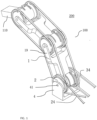
- Fig. 1 shows a perspective view of a multi-arm device 200 according to the present invention.
- the multi-arm device 200 includes two joint mechanisms 100 according to the present invention connected to each other. It is easy to understand that the multi-arm device 200 may include more joint mechanisms 100 connected to each other.
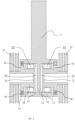
- the joint mechanism 100 includes a base 4 having a pivot shaft 41, and a swinging arm 1 mounted on the pivot shaft 41.
- the swinging arm 1 is mounted on the pivot shaft 41 through a first end 11 thereof (see Fig. 2 ).
- the first end 11 of the swinging arm 1 is formed as a sleeve-shaped structure, the center of which is provided with a partition wall 12 extending in a radial direction.
- the sleeve-shaped first end 11 is divided into two recesses adjacent to each other in an axial direction by the partition wall 12, namely a first recess 13 and a second recess 14.
- the terms "axial” and "radial" are defined with respect to the pivot shaft 41.
- the pivot shaft 41 actually includes two pivot portions, which are respectively mounted in the first recess 13 and the second recess 14.
- the joint mechanism 100 further includes a first driving member 2 and a second driving member 3, which are mounted side by side on the pivot shaft 41. Both the first driving member 2 and the second driving member 3 can rotate under a driving force from a driving source (not shown). However, the rotation directions of the first driving member 2 and the second driving member 3 are set to be different from each other. In the embodiment as shown in Fig. 1 , the first driving member 2 can rotate in a clockwise direction, while the second driving member 3 can rotate in a counterclockwise direction.
- the driving source may be, for example, a motor.
- the first driving member 2 is formed as a hollow shaft, one end of which is open and the other end is closed.
- the pivot shaft 41 can extend into the open end of the first driving member 2, so that the first driving member 2 can be mounted on the pivot shaft 41 to rotate about the pivot shaft 41.
- the closed end of the first driving member 2 extends into the first recess 13 of the first end 11 of the swinging arm 1, so that the first driving member 2 and the swinging arm 1 together define a closed first liquid cavity 21, which is filled with magnetorheological fluid.
- the first driving member 2 is further provided on the outer periphery thereof with an annular shoulder 25 extending radially outward.
- the annular shoulder 25 is connected to the first end 11 of the swinging arm 1 through a bearing 26.
- a bearing stop 15 for mounting the bearing 26 is provided at the free end of the first recess 13 of the first end 11 of the swinging arm 1. Accordingly, the swinging arm 1 can be rotated under the driving force of the first driving member 2.
- a sealing element (not shown) is provided at the bearing 26.
- first driving member 2 and the swinging arm 1 can interact with each other through the magnetorheological fluid in the first liquid cavity 21, so as to establish a driving connection relationship.
- a first electromagnetic component 22 is provided in the first liquid cavity 21.
- the first electromagnetic component 22 can be configured, for example, as a ring-shaped member, which is sleeved on a portion 28 of the first driving member 2 extending into the first recess 13.
- the first electromagnetic component 22 is not disposed in the first liquid cavity 21, but out of the first liquid cavity 21, for example, at a side by the first liquid cavity 21. It is easy to understand that as long as the first electromagnetic component 22 can act on the magnetorheological fluid in the first liquid cavity 21 for changing its phase state, the position thereof can be arbitrarily selected by those skilled in the art according to the needs of the specific structure.
- the arrangement of the first electromagnetic component 22 in the first fluid cavity 21 can enable the structure of the entire joint mechanism 100 more compact, and the effect of the first electromagnetic component 22 on the magnetorheological fluid is more direct. Therefore, this arrangement is preferred.
- the first electromagnetic component 21 may be formed by a stator of a motor, which can be directly sleeved on the portion 28 of the first driving member 2 extending into the first recess 13, so that the assembly is very simple.
- a stator of a motor which can be directly sleeved on the portion 28 of the first driving member 2 extending into the first recess 13, so that the assembly is very simple.
- ready-made, high-quality stator of the motor can be obtained directly in markets. Therefore, it is unnecessary to design the stator independently, thus saving a large part of the cost.
- a shaftless motor stator can also be used.
- the first driving member 2 and the second driving member 3 have similar structures. Therefore, it is easy to understand that the description on the structure of the first driving member 2 can be similarly applicable to the second driving member 3.
- the second driving member 3 is also formed as a hollow shaft, with an open end and a closed end.
- the pivot shaft 41 extends into the open end of the second driving member 3, so that the second driving member 3 can be mounted on the pivot shaft 41 to rotate about the pivot shaft 41.
- the closed end of the second driving member 3 extends into the second recess 14, so that the second driving member 3 and the swinging arm 1 together define a closed second liquid cavity 31, which is filled with magnetorheological fluid.
- the second driving member 3 is further provided on the outer periphery thereof with an annular shoulder 35 extending radially outward.
- the annular shoulder 35 is connected to the first end 11 of the swinging arm 1 through a bearing 36.
- a bearing stop for mounting the bearing 36 is provided at the free end of the second recess 14 of the first end 11 of the swinging arm 1. Accordingly, the swinging arm 1 can be rotated under the driving force of the second driving member 3.
- a sealing element (not shown) is provided at the bearing 36. Accordingly, the second driving member 3 and the swinging arm 1 can interact with each other through the magnetorheological fluid in the second liquid cavity 31, so that a driving connection relationship can be established.
- a second electromagnetic component 32 is provided in the second liquid cavity 31.
- the second electromagnetic component 32 can be configured as a ring-shaped member, which is sleeved on a portion of the second driving member 3 extending into the second recess 14. It is easy to understand that as long as the second electromagnetic component 32 can act on the magnetorheological fluid in the second liquid cavity 31 to change its phase state, it can be arranged at another position.
- the second electromagnetic component 31 may be formed by a stator of a motor.
- the magnetorheological fluid in the first liquid cavity 21 or the second liquid cavity 31 will act as liquid with excellent flowability.
- no driving connection will be established between the first driving member 2 or the second driving member 3 and the swinging arm 1. That is, even if the first driving member 2 or the second driving member 3 rotates, the swinging arm 1 will not be driven into rotation.
- the first electromagnetic component 31 or the second electromagnetic component 3 is energized to generate a magnetic field, the magnetorheological fluid in the first liquid cavity 21 or the second liquid cavity 31 will act as solid under the influence of the magnetic field.
- a driving connection will be established between the first driving member 2 or the second driving member 3 and the swinging arm 1. That is, if the first driving member 2 or the second driving member 3 rotates, the swinging arm 1 is driven into rotation.
- the swinging arm 1 in the case where a driving connection is established between the first driving member 2 and the swinging arm 1, the swinging arm 1 will rotate clockwise when the first driving member 2 rotates clockwise. In the case where a driving connection is established between the second driving member 3 and the swinging arm 1, the swinging arm 1 will rotate counterclockwise when the second driving member 3 rotates counterclockwise. Since the magnetorheological fluid has a very fast response speed, the swinging arm 1 can follow the first driving member 2 or the second driving member 3 very quickly to rotate in two different directions of rotation.
- the joint mechanism 100 according to the present invention can realize forward rotation and reverse rotation of the swinging arm 1, as well as fast switching between two different rotation directions
- the specific movement modes of the joint mechanism 100 according to the present invention will be described in detail below.
- portions of the first driving member 2 and the second driving member 3 that extend into the first recess 13 and the first recess 14 respectively may be made of soft magnetic material, so as to facilitate the transmission of magnetic force.
- an encoder and a code reader may be provided on the first driving member 2 and the second driving member 3, so that the rotation angle of the swinging arm can be read and controlled.
- the driving source is connected to the first driving member 2 or the second driving member 3 through a transmission mechanism, so that the driving force can be transmitted to the first driving member 2 or the second driving member 3 to drive the first driving member 2 or the second driving member 3 into rotation.
- the transmission mechanism may be a pulley, a gear, a sprocket, a timing belt, or the like. Therefore, the inertia of the entire driving structure is very small, which is favorable for the swinging arm 1 to switch its moving direction rapidly.
- the transmission mechanism is a pulley and a transmission belt.
- the driving source drives the first driving member 2 through a first driving belt 24 and a first driving pulley 27 that cooperates therewith, and drives the second driving member 3 through a second driving belt 34 and a second driving pulley 37 that cooperates therewith.
- the first driving belt 24 adopts a cross-belt drive
- the second driving belt 34 adopts open-belt drive, so that the rotation directions of the first driving member 2 and the second driving member 3 are opposite to each other.
- first transmission belt 24 can adopt open-belt drive while the second transmission belt 34 adopt cross-belt drive, which can also achieve the above-mentioned effect.
- the first driving belt 24 adopts a semi-cross-belt drive
- the second driving belt 34 also adopts a semi-cross-belt drive, thereby ensuring that the rotation direction of the first driving member 2 is opposite to that of the second driving member 3.
- the transmission mechanism is a gear set.
- the rotation direction of the first driving member 2 can be opposite to that of the second driving member 3. This design also provides great flexibility for the arrangement of the rotation shaft of the drive source.
- the joint mechanism 100 is particularly capable of operating in several operation modes as described below.
- a first operation mode only a first current is applied to the first electromagnetic component 22, so that the magnetorheological fluid in the first liquid cavity 21 is in a phase state of high viscosity.
- a driving connection is established only between the first driving member 2 and the swinging arm 1. Accordingly, the first driving member 2 can drive the swinging arm 1 to rotate in a first direction, i.e., the clockwise direction in the illustrated embodiment.
- a second operation mode only a second current is applied to the second electromagnetic component 32, so that the magnetorheological fluid in the second liquid cavity 31 is in a phase state of high viscosity.
- a driving connection is established only between the second driving member 3 and the swinging arm 1. Accordingly, the second driving member 3 can drive the swinging arm 1 to rotate in the second direction, i.e., the counterclockwise direction in the illustrated embodiment.
- a third current and a fourth current are continuously applied to the first electromagnetic component 22 and the second electromagnetic component 32, respectively.
- the magnetorheological fluids in the first liquid cavity 21 and the second liquid cavity 31 are each in a phase state of high viscosity, so that driving connections are established between the first driving member 2 and the swinging arm 1, and also between the second driving member 3 and the swinging arm 1.
- the driving force exerted by the first driving member 2 on the swinging arm 1 can be made equal to that exerted by the second driving member 3 on the swinging arm 1, resulting in the swinging arm 1 being at a natural stationary state.
- the third current is less than or equal to the first current
- the fourth current is less than or equal to the second current.
- a fifth current and a sixth current are continuously applied to the first electromagnetic component 22 and/or the second electromagnetic component 32, respectively.
- the magnetorheological fluids in the first liquid cavity 21 and the second liquid cavity 31 are each in a phase state of high viscosity, so that driving connections are established between the first driving member 2 and the swinging arm 1, and also between the second driving member 3 and the swinging arm 1.
- the driving force exerted by the first driving member 2 and/or the second driving member 3 on the swinging arm 1 can counteract to the gravity of the swinging arm 1, resulting in the swinging arm 1 being at a stationary state.
- the fifth current and the sixth current are both pulse current.
- a seventh current and an eighth current are alternately applied to the first electromagnetic component 22 and the second electromagnetic component 32.
- the magnetorheological fluids in the first liquid cavity 21 and the second liquid cavity 31 present a highly viscous state alternatively, so that driving connections are established between the first driving member 2 and the swinging arm 1 and between the second driving member 3 and the swinging arm 1 in an alternate manner. Therefore, the first driving member 2 and the second driving member 3 can alternately drive the swinging arm 1 to rotate in different directions. That is, a reciprocating swing movement of the swinging arm 1 is realized.
- One or more of the above operation modes may be selected in sequence according to actual needs, so that various functions of the swinging arm 1 as required can be achieved.
- the multi-arm device 200 may include a plurality of joint mechanisms 100 connected to each other.
- two joint mechanisms 100 are connected to each other.
- the second end 19 of the swing arm 1 of an upstream joint mechanism 100 is formed as the base of a downstream joint mechanism 100.
- the transmission mechanism of the downstream joint mechanism 100 is connected to the first driving member 2 and the second driving member 3 of the upstream joint mechanism 100. That is, the first driving member 2 and the second driving member 3 of the upstream joint mechanism 100 act as the driving source of the downstream joint mechanism 100.
- these joint mechanisms 100 are connected one by one in sequence as described above.
- An arm 110 serving as an end effector may be arranged on the last joint mechanism 100 (i.e., the upper one in Fig. 1 ).
- the multi-arm device 200 has a very compact structure, and can achieve a more complex movement.
- only one driving source that provides a driving force for the first joint mechanism 100 is required to drive all the joint mechanisms. Therefore, the cost of the multi-arm device 200 is cut down, and the power consumption thereof is also greatly reduced.
- a robot which includes the joint mechanism 100 according to the present invention, or the multi-arm device 200 according to the present invention.
- the robot may be a single-joint robot, or a multi-joint robot.
Landscapes
- Engineering & Computer Science (AREA)
- Mechanical Engineering (AREA)
- Robotics (AREA)
- General Engineering & Computer Science (AREA)
- Manipulator (AREA)
- Transmission Devices (AREA)
- Devices For Conveying Motion By Means Of Endless Flexible Members (AREA)
Claims (11)
- Gelenkeinrichtung (100), aufweisend:eine Basis (4) mit einer Schwenkwelle (41),einen Schwenkarm (1), der an einem ersten Ende (11) der Schwenkwelle (41) angebracht ist;ein erstes Antriebselement (2) und ein zweites Antriebselement (3), die beide auf der Schwenkwelle (41) befestigt sind, um eine Antriebskraft von einer Antriebsquelle aufzunehmen, wobei das erste Antriebselement (2) bzw. das zweite Antriebselement (3) mit dem Schwenkarm (1) durch ein magnetrheologisches Fluid zusammenwirken, undein erstes elektromagnetisches Bauteil (22) und ein zweites elektromagnetisches Bauteil (32), die ausgestaltet sind, um den Phasenzustand des magnet-rheologischen Fluids zu ändern, so dass das erste Antriebselement (2) und das zweite Antriebselement (3) den Schwenkarm (1) selektiv antreiben können, um entlang einer ersten Richtung oder einer zweiten Richtung sich zu drehen, wobei die erste Richtung entgegengesetzt zur zweiten Richtung ist,dadurch gekennzeichnet, dass
das erste Antriebselement (2) und das zweite Antriebselement (3) zusammen mit dem Schwenkarm (1) einen geschlossenen, ersten Flüssigkeitshohlraum (21) bzw. einen geschlossenen, zweiten Flüssigkeitshohlraum (31) definieren, die beide mit der magnet-rheologischen Flüssigkeit gefüllt sind. - Gelenkeinrichtung nach Anspruch 1,wobei das erste Ende (11) des Schwenkarms (1) als eine Hülse ausgebildet ist, die durch eine Trennwand (12) in zwei Ausnehmungen (13, 14) unterteilt ist, die sich in radialer Richtung erstrecken, undwobei die offenen Enden der beiden Ausnehmungen (13, 14) durch das erste Antriebselement (2) durch das erste Antriebselement (2) bzw. das zweite Antriebselement (3) geschlossen sind, um den erste Flüssigkeitshohlraum (21) und den zweiten Flüssigkeitshohlraum (31) zu bilden.
- Gelenkeinrichtung nach Anspruch 2,wobei das erste Antriebselement (2) und das zweite Antriebselement (3) jeweils als Hohlwelle mit einem offenen Ende und einem geschlossenen Ende ausgebildet sind,die offenen Enden des ersten Antriebselements (2) und des zweiten Antriebselements (3) so ausgestaltet sind, dass die Schwenkwelle (41) darauf befestigt werden kann, und die geschlossenen Enden davon jeweils in die Ausnehmungen (13, 14) sich erstrecken, undjede Hohlwelle an einer äußeren Begrenzungsfläche davon mit einer ringförmigen Schulter (25, 35) versehen ist, die durch ein Lager (26, 36) abdichtend mit dem offenen Ende einer jeweiligen Ausnehmung (13, 14) verbunden ist, um den ersten Flüssigkeitshohlraum (21) oder den zweiten Flüssigkeitshohlraum (31) zu verschließen.
- Gelenkeinrichtung nach Anspruch 3,
wobei das erste elektromagnetische Bauteil (22) und das zweite elektromagnetische Bauteil (32) als ringförmige Elemente ausgebildet sind, die in dem ersten Flüssigkeitshohlraum (21) bzw. dem zweiten Flüssigkeitshohlraum (31) angeordnet sind und an den geschlossenen Enden des ersten Antriebselementes (2) bzw. des zweiten Antriebselementes (3) mit Verbindungsmuffen versehen sind. - Gelenkeinrichtung nach Anspruch 3,
wobei Teile des ersten Antriebselements (2) und des zweiten Antriebselements (3), die sich in die Ausnehmungen erstrecken, aus weichmagnetischem Material hergestellt sind. - Gelenkeinrichtung nach einem der Ansprüche 2 bis 3,
wobei das erste elektromagnetische Bauteil (22) und das zweite elektromagnetische Bauteil (32) an einer Seite an dem ersten Flüssigkeitshohlraum (21) bzw. an dem zweiten Flüssigkeitshohlraum (31) angeordnet sind. - Gelenkeinrichtung nach einem der Ansprüche 1 bis 5,
wobei die Antriebsquelle das erste Antriebselement (2) und das zweite Antriebselement (3) antreibt, um sich in der ersten Richtung bzw. in der zweiten Richtung durch eine Übertragungseinrichtung zu drehen, die aus einer Gruppe ausgewählt ist, bestehend aus einer Riemenscheibe, einem Getriebe, einem Kettenzahnrad und einem Riemen. - Gelenkeinrichtung nach Anspruch 7,wobei die Antriebsquelle das erste Antriebselement (2) durch einen ersten Riemen und eine erste Riemenscheibe antreibt und das zweite Antriebsglied (3) durch einen zweiten Riemen und eine zweite Riemenscheibe antreibt, undwobei der erste Riemen entweder eine Kreuzriemen-Antriebsart oder eine offene Riemen-Antriebsart annimmt, während der zweite Riemen die andere der Kreuzriemen-Antriebsart und der offenen Riemen-Antriebsart annimmt, oder der erste Riemen und der zweite Riemen nehmen beide eine Halbkreuzriemen-Antriebsart an.
- Gelenkeinrichtung nach einem der Ansprüche 1 bis 5,
wobei das erste Antriebselement (2) und das zweite Antriebselement (3) jeweils mit einem Sensor zur Erfassung des Drehwinkels des Schwenkarms (1) versehen sind. - Verfahren zur Steuerung der Gelenkeinrichtung nach einem der Ansprüche 1 bis 9, das einen Schritt aufweist:
des Anlegens von Strom an das erste elektromagnetische Bauteil (22) und / oder das zweite elektromagnetische Bauteil (32), um den Phasenzustand des magnet-rheologischen Fluids zu ändern, so dass mindestens entweder das erste Antriebselement (2) oder das zweite Antriebselement (3) den Schwenkarm (1) selektiv antreiben kann, um entlang der ersten Richtung oder der zweiten Richtung sich zu drehen. - Verfahren nach Anspruch 10, wobei das Verfahren irgendeinen oder mehrere der folgenden Betriebsarten aufweist:eine erste Betriebsart, in der nur ein erster Strom an das erste elektromagnetische Bauteil (22) angelegt wird, so dass das magnet-rheologische Fluid in dem ersten Flüssigkeitshohlraum seinen Phasenzustand ändert, was dazu führt, dass das erste Antriebselement (2) den Schwenkarm (1) zum Drehen in der ersten Richtung antreiben kann,eine zweite Betriebsart, in der nur ein zweiter Strom an das zweite elektromagnetische Bauteil (32) angelegt wird, so dass das magnet-rheologische Fluid in dem zweiten Flüssigkeitshohlraum seinen Phasenzustand ändert, was dazu führt, dass das zweite Antriebselement (3) den Schwenkarm (1) zum Drehen in die zweite Richtung antreiben kann;eine dritte Betriebsart, in der ein dritter Strom und ein vierter Strom kontinuierlich an das erste elektromagnetische Bauteil (22) bzw. das zweite elektromagnetische Bauteil (32) angelegt werden, so dass die magnet-rheologischen Fluide in dem ersten Flüssigkeitshohlraum (21) und dem zweiten Flüssigkeitshohlraum (31) beide ihre Phasenzustände ändern und eine von dem ersten Antriebselement (2) auf den Schwenkarm (1) ausgeübte Antriebskraft gleich der von dem zweiten Antriebselement (3) auf den Schwenkarm (1) ausgeübten Kraft ist, was dazu führt, dass sich der Schwingarm (1) in einem natürlichen stationären Zustand befindet;eine vierte Betriebsart, in der ein fünfter Strom und ein sechster Strom kontinuierlich an das erste elektromagnetische Bauteil (22) und / oder entsprechend das zweite elektromagnetische Bauteil (32) angelegt werden, so dass das magnet-rheologische Fluid in dem ersten Flüssigkeitshohlraum (21) und / oder dem zweiten Flüssigkeitshohlraum (31) seine Phasenzustände ändert, und eine durch das erste Antriebselement (2) und / oder das zweite Antriebselement (3) auf den Schwingarm (1) ausgeübte Antriebskraft einer Schwerkraft des Schwingarms (1) entgegenwirkt, was dazu führt, dass sich der Schwenkarm (1) in einem stationären Zustand befindet, wobei der fünfte Strom und der sechste Strom ein Impulsstrom ist, undeine fünfte Betriebsart, in der ein siebter Strom und ein achter Strom abwechselnd an das erste elektromagnetische Bauteil (22) und das zweite elektromagnetische Bauteil (32) angelegt werden, so dass die magnet-rheologischen Fluide in dem ersten Flüssigkeitshohlraum (21) und dem zweiten Flüssigkeitshohlraum (31) ihre Phasenzustände abwechselnd ändern und das erste Antriebselement (2) und das zweite Antriebselement (3) den Schwingarm (1) abwechselnd antreiben, so dass eine hin- und hergehende Schwenkbewegung des Schwenkarms (1) erzeugt wird.
Applications Claiming Priority (2)
| Application Number | Priority Date | Filing Date | Title |
|---|---|---|---|
| CN201710983085.3A CN107553481B (zh) | 2017-10-20 | 2017-10-20 | 关节机构及其控制方法、多臂装置和机器人 |
| PCT/CN2018/103218 WO2019076146A1 (zh) | 2017-10-20 | 2018-08-30 | 关节机构及其控制方法、多臂装置和机器人 |
Publications (4)
| Publication Number | Publication Date |
|---|---|
| EP3695940A1 EP3695940A1 (de) | 2020-08-19 |
| EP3695940A4 EP3695940A4 (de) | 2021-02-24 |
| EP3695940C0 EP3695940C0 (de) | 2023-06-21 |
| EP3695940B1 true EP3695940B1 (de) | 2023-06-21 |
Family
ID=60985633
Family Applications (1)
| Application Number | Title | Priority Date | Filing Date |
|---|---|---|---|
| EP18867648.0A Active EP3695940B1 (de) | 2017-10-20 | 2018-08-30 | Gelenkmechanismus und verfahren zur steuerung desselben |
Country Status (6)
| Country | Link |
|---|---|
| US (1) | US11254016B2 (de) |
| EP (1) | EP3695940B1 (de) |
| JP (1) | JP6960190B2 (de) |
| KR (1) | KR102512154B1 (de) |
| CN (1) | CN107553481B (de) |
| WO (1) | WO2019076146A1 (de) |
Families Citing this family (12)
| Publication number | Priority date | Publication date | Assignee | Title |
|---|---|---|---|---|
| CN107553481B (zh) | 2017-10-20 | 2023-07-18 | 广东奥马迪机器人有限公司 | 关节机构及其控制方法、多臂装置和机器人 |
| CN108527435B (zh) * | 2018-03-26 | 2022-03-22 | 哈尔滨工业大学深圳研究生院 | 一种基于磁流变液的连续可控变刚度机器人柔顺关节 |
| WO2020214520A1 (en) * | 2019-04-14 | 2020-10-22 | The Johns Hopkins University | Clutch system with phase changing materials |
| EP4100658B1 (de) * | 2020-02-06 | 2025-11-26 | Exonetik Inc. | Niederohmige betätigungseinrichtung mit magnetorheologischen flüssigkeitskupplungsvorrichtungen |
| CN111439322B (zh) * | 2020-05-19 | 2021-02-19 | 燕山大学 | 一种四足仿生机器人轻量化四自由度腿部机构 |
| WO2022031609A1 (en) * | 2020-08-04 | 2022-02-10 | Sri International | Serial manipulator for space applications |
| DE102020126705A1 (de) * | 2020-10-12 | 2022-04-14 | Hochschule Bremen | Gelenk mit kontrollierbaren Freiheitsgraden |
| CN112847424B (zh) * | 2020-12-24 | 2022-04-19 | 中国科学技术大学 | 一种刚度放大绳驱动单自由度关节 |
| CN114620485B (zh) * | 2021-09-07 | 2024-03-19 | 山东华世力自动化科技有限公司 | 一种玻璃切割一体机智能伺服驱动抓取系统 |
| CN114474018B (zh) * | 2022-03-04 | 2024-02-27 | 天津大学 | 一种基于磁流变液的被动负重下肢外骨骼膝关节装置 |
| CN118876109B (zh) * | 2024-09-29 | 2025-01-10 | 深圳市盛泰奇科技有限公司 | 一种具有极限保护装置的人形机器人关节模组 |
| CN119748501B (zh) * | 2024-12-30 | 2025-10-17 | 北京航空航天大学 | 一种基于线对称4u机构的变胞机器人关节 |
Family Cites Families (17)
| Publication number | Priority date | Publication date | Assignee | Title |
|---|---|---|---|---|
| JPS62264887A (ja) * | 1986-05-09 | 1987-11-17 | フアナツク株式会社 | ロボツトの回転検出機構 |
| US4896754A (en) * | 1988-08-25 | 1990-01-30 | Lord Corporation | Electrorheological fluid force transmission and conversion device |
| DE69622141T2 (de) * | 1996-01-11 | 2002-11-28 | Ford France S.A., Rueil-Malmaison | Magnetorheologisches Elastomer benutzende Buchse mit veränderlicher Steifigkeit |
| JPH09239686A (ja) * | 1996-03-06 | 1997-09-16 | Fujitsu Ltd | ロボットアーム |
| JP3863671B2 (ja) | 1998-07-25 | 2006-12-27 | 株式会社ダイヘン | 搬送用ロボット装置 |
| KR101060622B1 (ko) * | 2008-10-22 | 2011-08-31 | 한국과학기술원 | 유변유체를 이용한 다관절 장치 |
| US8127907B1 (en) * | 2009-02-03 | 2012-03-06 | White Brian R | Marine transmission using rheological fluids |
| US9566715B2 (en) * | 2009-10-09 | 2017-02-14 | The University Of Western Ontario | Magneto- and electro-rheological based actuators for human friendly manipulators |
| US9539731B2 (en) * | 2009-10-09 | 2017-01-10 | The University Of Western Ontario | Magneto-rheological clutch with sensors measuring electromagnetic field strength |
| CN103639903B (zh) * | 2013-11-25 | 2016-09-28 | 北京理工大学 | 三向关联调整磁射流体加工装置 |
| CN104723354B (zh) * | 2013-12-20 | 2016-08-17 | 中国科学院沈阳自动化研究所 | 一种机械阻抗参数可调的机器人柔性驱动旋转关节 |
| CN104493836A (zh) * | 2015-01-07 | 2015-04-08 | 中国科学院合肥物质科学研究院 | 一种基于磁流变液离合器的机器人关节结构 |
| EP3262312B1 (de) * | 2015-02-25 | 2023-07-05 | Société de Commercialisation des Produits de la Recherche Appliquée SOCPRA Sciences et Génie S.E.C. | Kabelbetriebenes system mit magnetorheologischen flüssigkeitskupplungsvorrichtungen |
| CN105099061A (zh) * | 2015-08-12 | 2015-11-25 | 上海交通大学 | 自驱动转动轴帆板驱动系统 |
| CN105856185A (zh) * | 2016-05-19 | 2016-08-17 | 清华大学 | 活塞驱动磁流柔性机器人手装置 |
| CN107553481B (zh) * | 2017-10-20 | 2023-07-18 | 广东奥马迪机器人有限公司 | 关节机构及其控制方法、多臂装置和机器人 |
| CN207509221U (zh) * | 2017-10-20 | 2018-06-19 | 广东奥马迪机器人有限公司 | 关节机构、多臂装置和机器人 |
-
2017
- 2017-10-20 CN CN201710983085.3A patent/CN107553481B/zh active Active
-
2018
- 2018-08-30 JP JP2020521588A patent/JP6960190B2/ja active Active
- 2018-08-30 US US16/756,856 patent/US11254016B2/en active Active
- 2018-08-30 KR KR1020207014118A patent/KR102512154B1/ko active Active
- 2018-08-30 EP EP18867648.0A patent/EP3695940B1/de active Active
- 2018-08-30 WO PCT/CN2018/103218 patent/WO2019076146A1/zh not_active Ceased
Also Published As
| Publication number | Publication date |
|---|---|
| CN107553481B (zh) | 2023-07-18 |
| EP3695940A1 (de) | 2020-08-19 |
| WO2019076146A1 (zh) | 2019-04-25 |
| KR102512154B1 (ko) | 2023-03-21 |
| EP3695940C0 (de) | 2023-06-21 |
| US20210187758A1 (en) | 2021-06-24 |
| KR20200070340A (ko) | 2020-06-17 |
| US11254016B2 (en) | 2022-02-22 |
| JP6960190B2 (ja) | 2021-11-05 |
| CN107553481A (zh) | 2018-01-09 |
| EP3695940A4 (de) | 2021-02-24 |
| JP2020537731A (ja) | 2020-12-24 |
Similar Documents
| Publication | Publication Date | Title |
|---|---|---|
| EP3695940B1 (de) | Gelenkmechanismus und verfahren zur steuerung desselben | |
| CN105934599B (zh) | 磁流变流体离合器设备和控制系统 | |
| US20130270056A1 (en) | Hybrid coded magnets and sma positive drive clutch | |
| JP5502818B2 (ja) | 変速磁気カップリング装置 | |
| JP4280817B2 (ja) | 非接触式負荷感応型自動変速機 | |
| EP3376068B1 (de) | Dualmodus-übertragungsmechanismus basierend auf der betätigung eines verdrillten strangs | |
| US20110266904A1 (en) | Permanent magnet actuator for adaptive actuation | |
| EP3659246B1 (de) | Magnetkupplungsvorrichtung | |
| KR101043822B1 (ko) | 동심 다축 제어 가능한 프로그래밍 전자석 액츄에이터 시스템 | |
| CA2553795C (en) | Eccentric screw pump with integrated drive | |
| EP1552177B1 (de) | Kupplung mit einem fluid mit variabler viskosität | |
| HK1249746A1 (en) | Joint mechanism and control method thereof, multiple-arm device and robot | |
| CN207509221U (zh) | 关节机构、多臂装置和机器人 | |
| CN114012776B (zh) | 一种多功能一体化关节模组 | |
| KR102567980B1 (ko) | 인간형 로봇 핸드 | |
| Berns et al. | Actuators | |
| KR100283129B1 (ko) | 형상기억합금과 전기유동유체를 이용한 회전형 작동기 | |
| JP2002031165A (ja) | 負荷感応型位置切換え装置、負荷感応型自動変速機用位置切換え装置及び負荷感応型自動変速機 | |
| KR102025010B1 (ko) | 상보성 기어감속을 이용한 엑추에이터 | |
| US20080121830A1 (en) | Hydraulic control valve system | |
| KR20100051290A (ko) | 동심 다축 제어 가능한 프로그래밍 전자석 액츄에이터 시스템 | |
| CN202597676U (zh) | 变速驱动装置 | |
| Bräunl | Actuators | |
| Yee et al. | Actuators in robotics and automation Systems | |
| JP6424554B2 (ja) | 転動直進変換装置 |
Legal Events
| Date | Code | Title | Description |
|---|---|---|---|
| STAA | Information on the status of an ep patent application or granted ep patent |
Free format text: STATUS: THE INTERNATIONAL PUBLICATION HAS BEEN MADE |
|
| PUAI | Public reference made under article 153(3) epc to a published international application that has entered the european phase |
Free format text: ORIGINAL CODE: 0009012 |
|
| STAA | Information on the status of an ep patent application or granted ep patent |
Free format text: STATUS: REQUEST FOR EXAMINATION WAS MADE |
|
| 17P | Request for examination filed |
Effective date: 20200512 |
|
| AK | Designated contracting states |
Kind code of ref document: A1 Designated state(s): AL AT BE BG CH CY CZ DE DK EE ES FI FR GB GR HR HU IE IS IT LI LT LU LV MC MK MT NL NO PL PT RO RS SE SI SK SM TR |
|
| AX | Request for extension of the european patent |
Extension state: BA ME |
|
| DAV | Request for validation of the european patent (deleted) | ||
| DAX | Request for extension of the european patent (deleted) | ||
| A4 | Supplementary search report drawn up and despatched |
Effective date: 20210126 |
|
| RIC1 | Information provided on ipc code assigned before grant |
Ipc: B25J 17/00 20060101ALI20210120BHEP Ipc: B25J 9/10 20060101AFI20210120BHEP Ipc: F16D 37/02 20060101ALI20210120BHEP Ipc: B25J 19/00 20060101ALI20210120BHEP Ipc: B25J 9/14 20060101ALI20210120BHEP |
|
| GRAP | Despatch of communication of intention to grant a patent |
Free format text: ORIGINAL CODE: EPIDOSNIGR1 |
|
| STAA | Information on the status of an ep patent application or granted ep patent |
Free format text: STATUS: GRANT OF PATENT IS INTENDED |
|
| INTG | Intention to grant announced |
Effective date: 20230228 |
|
| GRAS | Grant fee paid |
Free format text: ORIGINAL CODE: EPIDOSNIGR3 |
|
| GRAA | (expected) grant |
Free format text: ORIGINAL CODE: 0009210 |
|
| STAA | Information on the status of an ep patent application or granted ep patent |
Free format text: STATUS: THE PATENT HAS BEEN GRANTED |
|
| AK | Designated contracting states |
Kind code of ref document: B1 Designated state(s): AL AT BE BG CH CY CZ DE DK EE ES FI FR GB GR HR HU IE IS IT LI LT LU LV MC MK MT NL NO PL PT RO RS SE SI SK SM TR |
|
| REG | Reference to a national code |
Ref country code: CH Ref legal event code: EP |
|
| REG | Reference to a national code |
Ref country code: DE Ref legal event code: R096 Ref document number: 602018052232 Country of ref document: DE |
|
| REG | Reference to a national code |
Ref country code: AT Ref legal event code: REF Ref document number: 1580581 Country of ref document: AT Kind code of ref document: T Effective date: 20230715 |
|
| REG | Reference to a national code |
Ref country code: IE Ref legal event code: FG4D |
|
| U01 | Request for unitary effect filed |
Effective date: 20230627 |
|
| U07 | Unitary effect registered |
Designated state(s): AT BE BG DE DK EE FI FR IT LT LU LV MT NL PT SE SI Effective date: 20230717 |
|
| REG | Reference to a national code |
Ref country code: LT Ref legal event code: MG9D |
|
| PG25 | Lapsed in a contracting state [announced via postgrant information from national office to epo] |
Ref country code: NO Free format text: LAPSE BECAUSE OF FAILURE TO SUBMIT A TRANSLATION OF THE DESCRIPTION OR TO PAY THE FEE WITHIN THE PRESCRIBED TIME-LIMIT Effective date: 20230921 |
|
| PG25 | Lapsed in a contracting state [announced via postgrant information from national office to epo] |
Ref country code: RS Free format text: LAPSE BECAUSE OF FAILURE TO SUBMIT A TRANSLATION OF THE DESCRIPTION OR TO PAY THE FEE WITHIN THE PRESCRIBED TIME-LIMIT Effective date: 20230621 Ref country code: HR Free format text: LAPSE BECAUSE OF FAILURE TO SUBMIT A TRANSLATION OF THE DESCRIPTION OR TO PAY THE FEE WITHIN THE PRESCRIBED TIME-LIMIT Effective date: 20230621 Ref country code: GR Free format text: LAPSE BECAUSE OF FAILURE TO SUBMIT A TRANSLATION OF THE DESCRIPTION OR TO PAY THE FEE WITHIN THE PRESCRIBED TIME-LIMIT Effective date: 20230922 |
|
| U21 | Renewal fee for the european patent with unitary effect paid with additional fee |
Year of fee payment: 6 Effective date: 20231207 |
|
| PG25 | Lapsed in a contracting state [announced via postgrant information from national office to epo] |
Ref country code: SK Free format text: LAPSE BECAUSE OF FAILURE TO SUBMIT A TRANSLATION OF THE DESCRIPTION OR TO PAY THE FEE WITHIN THE PRESCRIBED TIME-LIMIT Effective date: 20230621 |
|
| PG25 | Lapsed in a contracting state [announced via postgrant information from national office to epo] |
Ref country code: ES Free format text: LAPSE BECAUSE OF FAILURE TO SUBMIT A TRANSLATION OF THE DESCRIPTION OR TO PAY THE FEE WITHIN THE PRESCRIBED TIME-LIMIT Effective date: 20230621 |
|
| PG25 | Lapsed in a contracting state [announced via postgrant information from national office to epo] |
Ref country code: IS Free format text: LAPSE BECAUSE OF FAILURE TO SUBMIT A TRANSLATION OF THE DESCRIPTION OR TO PAY THE FEE WITHIN THE PRESCRIBED TIME-LIMIT Effective date: 20231021 |
|
| PG25 | Lapsed in a contracting state [announced via postgrant information from national office to epo] |
Ref country code: SM Free format text: LAPSE BECAUSE OF FAILURE TO SUBMIT A TRANSLATION OF THE DESCRIPTION OR TO PAY THE FEE WITHIN THE PRESCRIBED TIME-LIMIT Effective date: 20230621 Ref country code: SK Free format text: LAPSE BECAUSE OF FAILURE TO SUBMIT A TRANSLATION OF THE DESCRIPTION OR TO PAY THE FEE WITHIN THE PRESCRIBED TIME-LIMIT Effective date: 20230621 Ref country code: RO Free format text: LAPSE BECAUSE OF FAILURE TO SUBMIT A TRANSLATION OF THE DESCRIPTION OR TO PAY THE FEE WITHIN THE PRESCRIBED TIME-LIMIT Effective date: 20230621 Ref country code: IS Free format text: LAPSE BECAUSE OF FAILURE TO SUBMIT A TRANSLATION OF THE DESCRIPTION OR TO PAY THE FEE WITHIN THE PRESCRIBED TIME-LIMIT Effective date: 20231021 Ref country code: ES Free format text: LAPSE BECAUSE OF FAILURE TO SUBMIT A TRANSLATION OF THE DESCRIPTION OR TO PAY THE FEE WITHIN THE PRESCRIBED TIME-LIMIT Effective date: 20230621 Ref country code: CZ Free format text: LAPSE BECAUSE OF FAILURE TO SUBMIT A TRANSLATION OF THE DESCRIPTION OR TO PAY THE FEE WITHIN THE PRESCRIBED TIME-LIMIT Effective date: 20230621 |
|
| PG25 | Lapsed in a contracting state [announced via postgrant information from national office to epo] |
Ref country code: PL Free format text: LAPSE BECAUSE OF FAILURE TO SUBMIT A TRANSLATION OF THE DESCRIPTION OR TO PAY THE FEE WITHIN THE PRESCRIBED TIME-LIMIT Effective date: 20230621 |
|
| PG25 | Lapsed in a contracting state [announced via postgrant information from national office to epo] |
Ref country code: MC Free format text: LAPSE BECAUSE OF FAILURE TO SUBMIT A TRANSLATION OF THE DESCRIPTION OR TO PAY THE FEE WITHIN THE PRESCRIBED TIME-LIMIT Effective date: 20230621 |
|
| REG | Reference to a national code |
Ref country code: DE Ref legal event code: R097 Ref document number: 602018052232 Country of ref document: DE |
|
| PG25 | Lapsed in a contracting state [announced via postgrant information from national office to epo] |
Ref country code: MC Free format text: LAPSE BECAUSE OF FAILURE TO SUBMIT A TRANSLATION OF THE DESCRIPTION OR TO PAY THE FEE WITHIN THE PRESCRIBED TIME-LIMIT Effective date: 20230621 |
|
| PLBE | No opposition filed within time limit |
Free format text: ORIGINAL CODE: 0009261 |
|
| STAA | Information on the status of an ep patent application or granted ep patent |
Free format text: STATUS: NO OPPOSITION FILED WITHIN TIME LIMIT |
|
| REG | Reference to a national code |
Ref country code: IE Ref legal event code: MM4A |
|
| 26N | No opposition filed |
Effective date: 20240322 |
|
| PG25 | Lapsed in a contracting state [announced via postgrant information from national office to epo] |
Ref country code: IE Free format text: LAPSE BECAUSE OF NON-PAYMENT OF DUE FEES Effective date: 20230830 |
|
| PG25 | Lapsed in a contracting state [announced via postgrant information from national office to epo] |
Ref country code: IE Free format text: LAPSE BECAUSE OF NON-PAYMENT OF DUE FEES Effective date: 20230830 |
|
| U20 | Renewal fee for the european patent with unitary effect paid |
Year of fee payment: 7 Effective date: 20240821 |
|
| PG25 | Lapsed in a contracting state [announced via postgrant information from national office to epo] |
Ref country code: CY Free format text: LAPSE BECAUSE OF FAILURE TO SUBMIT A TRANSLATION OF THE DESCRIPTION OR TO PAY THE FEE WITHIN THE PRESCRIBED TIME-LIMIT; INVALID AB INITIO Effective date: 20180830 |
|
| PG25 | Lapsed in a contracting state [announced via postgrant information from national office to epo] |
Ref country code: HU Free format text: LAPSE BECAUSE OF FAILURE TO SUBMIT A TRANSLATION OF THE DESCRIPTION OR TO PAY THE FEE WITHIN THE PRESCRIBED TIME-LIMIT; INVALID AB INITIO Effective date: 20180830 |
|
| U20 | Renewal fee for the european patent with unitary effect paid |
Year of fee payment: 8 Effective date: 20250813 |
|
| PGFP | Annual fee paid to national office [announced via postgrant information from national office to epo] |
Ref country code: GB Payment date: 20250822 Year of fee payment: 8 |
|
| PGFP | Annual fee paid to national office [announced via postgrant information from national office to epo] |
Ref country code: CH Payment date: 20250901 Year of fee payment: 8 |
|
| PG25 | Lapsed in a contracting state [announced via postgrant information from national office to epo] |
Ref country code: TR Free format text: LAPSE BECAUSE OF FAILURE TO SUBMIT A TRANSLATION OF THE DESCRIPTION OR TO PAY THE FEE WITHIN THE PRESCRIBED TIME-LIMIT Effective date: 20230621 |