EP3659246B1 - Magnetkupplungsvorrichtung - Google Patents
Magnetkupplungsvorrichtung Download PDFInfo
- Publication number
- EP3659246B1 EP3659246B1 EP18755551.1A EP18755551A EP3659246B1 EP 3659246 B1 EP3659246 B1 EP 3659246B1 EP 18755551 A EP18755551 A EP 18755551A EP 3659246 B1 EP3659246 B1 EP 3659246B1
- Authority
- EP
- European Patent Office
- Prior art keywords
- magnets
- coupling device
- members
- row
- magnetic coupling
- Prior art date
- Legal status (The legal status is an assumption and is not a legal conclusion. Google has not performed a legal analysis and makes no representation as to the accuracy of the status listed.)
- Active
Links
Images


Classifications
-
- H—ELECTRICITY
- H02—GENERATION; CONVERSION OR DISTRIBUTION OF ELECTRIC POWER
- H02K—DYNAMO-ELECTRIC MACHINES
- H02K49/00—Dynamo-electric clutches; Dynamo-electric brakes
- H02K49/10—Dynamo-electric clutches; Dynamo-electric brakes of the permanent-magnet type
- H02K49/104—Magnetic couplings consisting of only two coaxial rotary elements, i.e. the driving element and the driven element
- H02K49/106—Magnetic couplings consisting of only two coaxial rotary elements, i.e. the driving element and the driven element with a radial air gap
-
- B—PERFORMING OPERATIONS; TRANSPORTING
- B67—OPENING, CLOSING OR CLEANING BOTTLES, JARS OR SIMILAR CONTAINERS; LIQUID HANDLING
- B67B—APPLYING CLOSURE MEMBERS TO BOTTLES JARS, OR SIMILAR CONTAINERS; OPENING CLOSED CONTAINERS
- B67B3/00—Closing bottles, jars or similar containers by applying caps
- B67B3/20—Closing bottles, jars or similar containers by applying caps by applying and rotating preformed threaded caps
- B67B3/2073—Closing bottles, jars or similar containers by applying caps by applying and rotating preformed threaded caps comprising torque limiting means
- B67B3/2086—Magnetic or electromagnetic clutches
-
- H—ELECTRICITY
- H02—GENERATION; CONVERSION OR DISTRIBUTION OF ELECTRIC POWER
- H02K—DYNAMO-ELECTRIC MACHINES
- H02K49/00—Dynamo-electric clutches; Dynamo-electric brakes
- H02K49/10—Dynamo-electric clutches; Dynamo-electric brakes of the permanent-magnet type
-
- H—ELECTRICITY
- H02—GENERATION; CONVERSION OR DISTRIBUTION OF ELECTRIC POWER
- H02K—DYNAMO-ELECTRIC MACHINES
- H02K49/00—Dynamo-electric clutches; Dynamo-electric brakes
- H02K49/06—Dynamo-electric clutches; Dynamo-electric brakes of the synchronous type
- H02K49/065—Dynamo-electric clutches; Dynamo-electric brakes of the synchronous type hysteresis type
Definitions
- This invention relates to the devices for transmitting a rotary motion among a plurality of members, and more particularly it concerns a magnetic coupling device.
- Japanese Published Patent Application JP H 9280341 A discloses a device for transmitting rotation from a driving shaft to a driven shaft, which shafts are coaxially arranged and have, on their facing surfaces, a plurality of axially extending magnetised areas, each area having the same polarity over the whole of its axial extension.
- the driven shaft is carried by a slide allowing it to slide relative to the driving shaft.
- Each magnetised area can consist of a row of axially aligned magnets, and the magnets in different rows on each shaft form bands perpendicular to the axis of the respective shaft.
- the magnets can be elongated magnets having the same polarity and located adjacent to one another in the respective area or row.
- the magnets in the different areas or rows can be arranged in an echelon configuration.
- a magnet in a row has opposite polarity with respect to both the preceding and the following magnet in the same row and the neighbouring magnets in the adjacent rows.
- the magnets can be provided on both members, or one member can have the magnetised areas and the other can be made of a material having magnetic hysteresis properties (hysteretic material).
- the invention also provides a capping head according to claim 5 for applying for instance screw or pressure caps to containers, wherein a cap application part can be driven according to a rotary movement about a longitudinal axis and a translatory movement along said axis through a magnetic coupling device according to the invention.
- a turret of a capping machine including a plurality of capping heads according to the invention mounted on a rotating structure of the turret and fixedly connected for rotation to said structure.
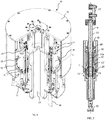
- Device 1 consists of an inner cylindrical rotor 10 and an outer cylindrical rotor 11, coaxially mounted on inner rotor 10 and preferably having a smaller length than the latter.
- Reference symbol A denotes the longitudinal axis of both rotors.
- rotors 10 and 11 besides performing a rotary motion, are also translatable relative to each other. Possibly, they can be guided in their rotary and translatory movements by rolling bearings and sliding bushings, or by bushings enabling both movements at the same time.
- the sliding bushings can even be dispensed with.
- such guiding means have not been shown.
- they are not part of the invention and are wholly conventional and well known to the skilled in the art, so that a detailed description thereof is not necessary.
- outer rotor 11 receives the roto-translatory motion from external driving members and is to transmit such a motion to inner rotor 10.
- rotor 11 has a flange 15 for fastening to devices controlling the movement (not shown).
- the external driving members apply the rotary motion to one rotor and the translatory motion to the other rotor.
- rotors 10 and 11 have, on their facing surfaces, a plurality of elongated magnets 12 and 13, respectively, which extend in axial direction and are distributed over substantially the whole circumference of inner rotor 10 and outer rotor 11.
- each magnet 12, 13 is made of a single element.
- Magnets 12 and 13 can be elements applied to inner rotor 10 and outer rotor 11, and they are attached to the rotors in any suitable manner, for instance by gluing.
- magnets 12 and 13 are magnetised in radial direction and are arranged with alternating polarities.
- the two sets of magnets can comprise the same or a different number of magnets, depending on the application.
- magnets 12 on inner rotor 10 will have a greater length than magnets 13 on outer rotor 11.
- the gap between facing magnets 12, 13 is such as to ensure a high magnetic force transmission between the rotors and the absence of contact also during operation.
- a sleeve 14 with smooth surface, made for instance of a non-magnetic material, is located between the two magnet sets. Such a sleeve serves to contain magnets 12 and to protect them from contamination, as well as to reduce fluid turbulence at the air gap.
- the smooth surface makes sliding between outer rotor 11 and inner rotor 10 easier.
- each long magnet 12 in rotor 10 is made of a row of short magnets 12' that are radially polarised in the same direction, are axially aligned and are adjacent to one another.
- the construction with rows of axially aligned short magnets is possible also for the magnets in outer rotor 11, as shown by magnets 13' in Fig. 2 .
- magnets 12', 13' are elements applied, e.g. glued, to the surfaces of rotors 10, 11.
- the individual short magnets 12' in the different rows are mutually offset so that their ends are not aligned to form a circumference perpendicular to the rotor axis, as shown in Fig. 3 for magnet rows 12i, 12j.
- the reasons for the offset arrangement will become apparent from the sequel of the description.
- Fig. 4 shows another offset arrangement of the magnets in case of a coupling device 101 intended to transmit the only rotary motion.
- reference numerals corresponding to those used in Fig. 2 increased by 100, have been used.
- device 101 parallel rows of magnets 112', 113' are still provided on rotors 110, 111, but the magnets, instead of having an elongated shape, have substantially the same size in both perpendicular directions, when viewed in plan, and are arranged in echelon over substantially the whole circumference of the rotors.
- Adjacent magnets 112', 113' are arranged in the echelon with alternating polarities, both along a row and among contiguous rows. Magnets 112', 113' could even be located at a certain distance from one another, instead of being substantially in mutual contact as shown in the Figure.
- a coupling device with magnets having an elongated shape as in Fig. 2 , and arranged in echelon
- a coupling device with magnets having, when viewed in plan, substantially the same size in both perpendicular directions as in Fig. 4 , and arranged in rows of magnets that are radially polarised in the same direction and are polarised in opposite direction with respect to the magnets of adjacent rows.
- the magnets can have further shapes, provided such shapes are compatible with the aim of the present invention.
- Figs. 1 to 4 relate to a coupling device using synchronous magnets. Yet, the invention could also be applied in a hysteresis coupling device, in which one of the two rotors is provided with permanent magnets 12 (12', 112') and 13 (13', 113'), respectively, and the other one is made of a ferromagnetic material having magnetic hysteresis properties, for instance alnico. Other materials having magnetic hysteresis properties are well known to the skilled in the art.
- coupling device 1 The operation of coupling device 1 will now be described, assuming by way of example, as stated above, that outer rotor 11 is the driving unit connected to external driving members, and inner rotor 10 is the driven unit.
- outer rotor 11 drags inner rotor 10 with itself until a threshold axial force, it too set in known manner at the assembling of the device, is exceeded. Once that threshold has been exceeded, outer rotor 11 (which, in the example considered, has a smaller length than inner rotor 10) can slide along the common axis over the whole length of magnets 12 of inner rotor 10, thereby continuously transmitting the torsion torque to inner rotor 10 over the whole length of magnets 12.
- Figs. 5A to 5C show three relative positions of the two rotors, more particularly two extreme positions in which the magnets of outer rotor 11 are aligned with the lower end ( Fig. 5A ) or the upper end ( Fig.
- magnets 13 find a stability point and stop their longitudinal movement.
- a stop function is obtained without the need to provide a mechanical stop to prevent the rotors from slipping off from each other. If an axial longitudinal force is applied on rotor 11 to push it out of the stability position, a reaction effect similar to the effect caused by a spring occurs.
- magnets 12 are made as axial rows of short magnets 12' adjacent to one another and arranged so as to form bands perpendicular to axis A, as shown in Fig. 2 , the stability points are the ends of individual magnets 12', whereby the translatory movement of rotor 11 would take place by discrete steps.
- This drawback is obviated by the arrangement according to the invention shown in Fig. 3 , where short magnets 12' in adjacent rows are offset, so that a succession of stability positions no longer exists at the circumferences passing through the ends of magnets 12'. The movement of rotor 11 is therefore continuous.
- Adoption of such a solution results in a function of magnetic self-centring of rotors 10, 11, which are subject to opposing radial forces that cancel each other, whereby rolling bearings are not necessary since the two rotors fluctuate on each other thanks to the natural magnetic levitation.
- a hysteresis coupling device in which only one of rotors 110, 111 has the magnets arranged in echelon, whereas the other rotor is made of a hysteretic material. Magnetisation of the hysteretic material by the permanent magnets results in continuous stability positions. In this case, besides a torque limiting effect, also a dampening effect is obtained after the resistance thresholds of the magnetic coupling have been exceeded. The lack of rigidity of the system allows compensating mechanical clearances.
- the invention can be applied in different technical fields, including moving an encoder-like rotating member on a shaft that simultaneously rotates and translates or in roto-translating pistons of capping heads for applying for instance screw or pressure caps to containers, more particularly bottles.
- a capping machine generally comprises at least one capping head, in turn including a cap application part, having a cap gripping member which is generally made to move according to a rotary movement about a longitudinal axis and a translatory movement along said axis, and a driving part, for instance located axially above the cap application part.
- the axial sliding of the gripping member also serves for applying a top load necessary to keep the container to be capped blocked during the capping operation.
- one or more springs allow adjusting such a load.
- FIG. 6 shows, by way of example, a capping turret 20 preferably including a plurality of capping heads 21, each incorporating coupling device 1.
- Turret 20 includes a stationary frame 22, inside which there is mounted a rotating structure 23, to which heads 21 are fixedly connected for rotation. Rotation of structure 23 allows bringing capping heads 21 in correspondence of bottles 26.
- the means for causing rotation of structure 23 are conventional and are not shown.
- each head 21 is configured as a piston with a rod 24, which is to be driven into the roto-translatory motion necessary for the capping operations and which carries, at its bottom, gripping member 25 for the cap to be applied to a bottle 26.
- rod 24 is provided with means 27 for connection to members belonging to the driving part (not shown) and causing the axial sliding of the rod under the control, for instance, of cams.
- Reference symbol B denotes the axis of rotation of rod 24.
- a central portion of rod 24 is coaxially inserted into a sleeve 28 rotatably mounted, as indicated by bearings or bushings 29, in a cylindrical body 30 fixedly connected for rotation to rotating structure 23 of turret 20. More particularly, cylindrical bodies 30 of all heads are fastened to a flange 31 in structure 23. Cylindrical body 30 is open at both bases to allow translation of rod 24. Cylindrical body 30 accommodates stator 32 of an electric motor for generating the rotary motion to be imparted to rod 24 through magnetic coupling device 1 according to the present invention. Sleeve 28 forms the rotor of said electric motor.
- rod 24 has a portion 24a of reduced diameter, which is intended to form the inner rotor of a magnetic coupling device 1 ( Figs. 1 to 4 ) and to which the magnets are therefore applied.
- rod 24 has a plurality of parallel longitudinal rows of elongated permanent magnets 12', the ends of which are offset so that they do not lie on a same circumference perpendicular to the axis of rod 24. That is, the magnet arrangement depicted in Fig. 3 has been adopted, in order to allow a continuous sliding of rod 24.
- outer magnets 13' are offset relative to magnets 12' applied to rod 24.
- head 21 The operation of head 21 is as follows.
- a coupling device for transmitting a roto-translatory motion it is possible to have three coaxial rotors, of which the innermost rotor and the outermost rotor have a shorter length than the central rotor (and hence have magnets shorter than the magnets in the latter) and are axially slidable relative to the central rotor.
- the innermost rotor and the outermost rotor have a shorter length than the central rotor (and hence have magnets shorter than the magnets in the latter) and are axially slidable relative to the central rotor.
- a hysteresis coupling device could be used also in capping heads 21 of turret 20 in place of a coupling device with synchronous magnets, as shown in Figs. 6 to 8 .
Landscapes
- Engineering & Computer Science (AREA)
- Power Engineering (AREA)
- Physics & Mathematics (AREA)
- Electromagnetism (AREA)
- Mechanical Engineering (AREA)
- Dynamo-Electric Clutches, Dynamo-Electric Brakes (AREA)
Claims (8)
- Magnetkupplungsvorrichtung (1) zum Koppeln von wenigstens einem ersten und zweiten Teil (10, 11), die zueinander koaxial sind, sodass sie in Abhängigkeit von der Stärke eines auf eines der Teile ausgeübten Drehmoments zumindest eine gemeinsame Drehbewegung um eine gemeinsame Achse (A) oder eine relative Drehbewegung ausführen können, wobei wenigstens eines dieser Teile (10, 11) sich in axialer Richtung erstreckende magnetisierte Bereiche aufweist, die jeweils aus einer Reihe von axial ausgerichteten Magneten (12', 13') bestehen,
wobei zum Koppeln des wenigstens einen ersten und zweiten Teils (10, 11), sodass sie zusätzlich zu den genannten Drehbewegungen in Abhängigkeit von der Stärke einer axialen Kraft, die auf eines der Teile ausgeübt wird, auch eine gemeinsame translatorische Bewegung entlang der Achse oder eine relative translatorische Bewegung durchführen können, die Magnete in den verschiedenen Reihen Magnete (12', 13') mit derselben Polarität sind, die aneinander angrenzend in der entsprechenden Reihe angeordnet sind, wobei die Magnete (12', 13') in einer Reihe in Bezug auf die Magnete (12', 13') in den angrenzenden Reihen entgegengesetzte Polarität haben und dadurch gekennzeichnet, dass die Magnete (12', 13') in einer Reihe axial in Bezug auf die Magnete einer angrenzenden Reihe versetzt sind, sodass die Enden der Magnete von verschiedenen Reihen nicht zum Bilden eines Umfangs senkrecht zu der Achse (A) des ersten und zweiten Teils (10, 11) ausgerichtet sind. - Magnetkupplungsvorrichtung (1) nach Anspruch 1, wobei die magnetisierten Bereiche an den wenigstens zwei Teilen (10, 11) vorgesehen sind.
- Magnetkopplungsvorrichtung (1) nach Anspruch 1, wobei eines der wenigstens zwei Teile die magnetisierten Bereiche (12', 13') hat und das andere aus einem Material ist, das magnetische Hysterese-Eigenschaften hat.
- Magnetkopplungsvorrichtung nach Anspruch 1 zum Koppeln von drei Teilen, die koaxial zueinander angeordnet sind, wobei das innerste Teil und das äußerste Teil dazu in der Lage sind, sich axial relativ zu einem mittleren Teil zu verschieben, und wobei die axiale Verschiebebewegung des innersten und des äußersten Teils in unterschiedlichen Richtungen erfolgen kann.
- Verschließkopf (21) mit einem Verschlussaufsetzteil (24, 25), das mit einem verschlussgreifenden Teil (25) versehen und dafür ausgelegt ist, sich gemäß einer Drehbewegung um eine Längsachse (B) und eine translatorische Bewegung entlang der Achse zu bewegen, und einem Antriebsteil (27, 28, 32) für das Verschlussaufsetzteil (24, 25), wobei das Antriebsteil (27, 28, 32) dafür ausgelegt ist, die Drehbewegung und die translatorische Bewegung auf das Verschlussaufsetzteils (24, 25) durch eine magnetische Kopplungsvorrichtung (1) zu übertragen, die dafür ausgelegt ist, ein erstes und ein zweites Teil (10, 11), die koaxial zueinander angeordnet sind, und jeweils zu dem Verschlussaufsetzteil (24, 25) bzw. dem Antriebsteil (27, 28, 32) gehören, miteinander zu koppeln, und wobei wenigstens eines der Teile (10, 11) sich axial erstreckende magnetisierte Bereiche aufweist, die jeweils aus einer Reihe von axial ausgerichteten Magneten (12', 13') bestehen, dadurch gekennzeichnet, dass die Magnete (12', 13') der verschiedenen Reihen in der jeweiligen Reihe aneinander angrenzend angeordnet sind und die Magnete (12', 13')in einer Reihe in Bezug auf die Magnete einer angrenzenden Reihe axial versetzt angeordnet sind, sodass Enden der Magnete von verschiedenen Reihen nicht zum Bilden eines Umfangs senkrecht zur Achse (A) des ersten und zweiten Teils (10, 11) ausgerichtet sind.
- Verschließkopf (21) nach Anspruch 5, wobei das Verschlussaufsetzteil (24, 25) eine axial verschiebbare Stange (24) aufweist, die in einem zentralen Bereich einen Abschnitt (24a) mit reduzierten Durchmesser hat, der eines der gekoppelten Teile der Magnetkupplungsvorrichtung bildet und koaxial in einer Hülse (28) angeordnet ist, die den Roter eines Elektromotors zum Erzeugen der durch die Magnetkopplungsvorrichtung (1) auf die Stange (24) zu übertragenden Drehbewegung bildet, wobei die Hülse (28) drehfest an einem Teil (33) befestigt ist, das ein zweites (33) der gekoppelten Teile der Magnetkupplungsvorrichtung bildet.
- Verschließkopf (21) nach Anspruch 6, wobei die Hülse (28) drehbar und verschiebbar in einem Gehäuse (30) montiert ist, das von einer drehbaren Struktur (23) eines Drehkreuzes (20) einer Verschließmaschine getragen wird, die mehrere Verschließköpfe (21) aufweist und einen Stator (32) des Elektromotors aufnimmt
- Drehkreuz (20) einer Verschlussmaschine, die mehrere Kappenköpfe (21) nach Anspruch 6 oder 7 aufweist, die auf einer drehbaren Struktur (23) des Drehkreuzes (20) montiert und drehfest an der Struktur befestigt sind.
Applications Claiming Priority (2)
| Application Number | Priority Date | Filing Date | Title |
|---|---|---|---|
| IT102017000084310A IT201700084310A1 (it) | 2017-07-24 | 2017-07-24 | Dispositivo di accoppiamento magnetico |
| PCT/IB2018/055321 WO2019021117A1 (en) | 2017-07-24 | 2018-07-18 | MAGNETIC COUPLING DEVICE |
Publications (2)
| Publication Number | Publication Date |
|---|---|
| EP3659246A1 EP3659246A1 (de) | 2020-06-03 |
| EP3659246B1 true EP3659246B1 (de) | 2021-09-08 |
Family
ID=60451044
Family Applications (1)
| Application Number | Title | Priority Date | Filing Date |
|---|---|---|---|
| EP18755551.1A Active EP3659246B1 (de) | 2017-07-24 | 2018-07-18 | Magnetkupplungsvorrichtung |
Country Status (6)
| Country | Link |
|---|---|
| US (1) | US11374481B2 (de) |
| EP (1) | EP3659246B1 (de) |
| CN (1) | CN110999050B (de) |
| ES (1) | ES2899258T3 (de) |
| IT (1) | IT201700084310A1 (de) |
| WO (1) | WO2019021117A1 (de) |
Families Citing this family (4)
| Publication number | Priority date | Publication date | Assignee | Title |
|---|---|---|---|---|
| IT201600106129A1 (it) | 2016-10-21 | 2018-04-21 | Arol Spa | Testa di tappatura per applicazione di capsule su contenitori o bottiglie |
| IT201600106100A1 (it) | 2016-10-21 | 2018-04-21 | Arol Spa | Testa di tappatura per applicazione di capsule su contenitori o bottiglie |
| IT202000014836A1 (it) | 2020-06-22 | 2021-12-22 | Arol Spa | Dispositivo di manipolazione di contenitori per impianti di tappatura |
| CN117185223B (zh) * | 2023-11-07 | 2024-02-02 | 江苏尚纯自动化技术有限公司 | 一种用于物料包装的保压旋盖头及保压旋盖机构 |
Family Cites Families (34)
| Publication number | Priority date | Publication date | Assignee | Title |
|---|---|---|---|---|
| ES397076A1 (es) | 1970-11-11 | 1975-03-01 | Mauceri Borghetto Alluminio | Perfeccionamientos en los cabezales para maquinas rebordea-doras yno roscadoras. |
| CH601097A5 (de) | 1976-06-22 | 1978-06-30 | Obrist Ag Albert | |
| DE2650294C3 (de) * | 1976-11-02 | 1981-08-27 | Gerhard Walter Prof. Dr.-Ing. 5630 Remscheid Seulen | Magnetische Kupplung für Geräte zur Strömungs-, Druck- oder Niveauüberwachung flüssiger oder gasförmiger Medien |
| US4535583A (en) | 1982-10-04 | 1985-08-20 | Shibuya Kogyo Co., Ltd. | Rotary type capping apparatus |
| US4808869A (en) * | 1987-11-18 | 1989-02-28 | Sundstrand Corp. | Integral magnetic torque limiting coupling/motor |
| DE3807083A1 (de) * | 1988-03-04 | 1989-09-14 | Burgmann Dichtungswerk Feodor | Magnetische vorrichtung zur uebertragung von drehkraeften |
| US5313765A (en) * | 1991-11-04 | 1994-05-24 | Anderson-Martin Machine Company | Capping machine head with magnetic clutch |
| JP3373355B2 (ja) | 1996-04-08 | 2003-02-04 | シーケーディ株式会社 | 回転伝達装置 |
| IT1318836B1 (it) * | 2000-09-08 | 2003-09-10 | Marco Cipriani | Dispositivo ad accoppiamento magnetico per la trasmissione e lamisurazione di coppia. |
| AT500459B1 (de) | 2004-01-23 | 2010-08-15 | Greiner Bio One Gmbh | Verfahren zum zusammenbau einer kappe mit einem aufnahmebehälter |
| DE102006007924A1 (de) * | 2006-02-21 | 2007-08-30 | Saurer Gmbh & Co. Kg | Verfahren zum Einstellen eines Bremsmomentes und Magnethysteresebremse |
| CN2937089Y (zh) | 2006-08-16 | 2007-08-22 | 谢海燕 | 一种手动防开裂旋盖扳手 |
| ITBO20070546A1 (it) | 2007-08-02 | 2009-02-03 | Acma Spa | Apparecchiatura di presa per gruppi tappatori in macchine per il confezionamento di contenitori. |
| DE102007037186B3 (de) * | 2007-08-07 | 2008-10-30 | Muammer Yildiz | Vorrichtung mit einer Anordnung von Magneten |
| EP2031407B1 (de) * | 2007-08-29 | 2012-06-06 | F. Hoffmann-La Roche AG | Kappenentnahmesystem |
| ITTO20080712A1 (it) * | 2008-09-30 | 2010-04-01 | Arol Spa | Macchina per l'applicazione di capsule filettate a contenitori |
| CN201309820Y (zh) | 2008-11-26 | 2009-09-16 | 秦鸿杲 | 气囊式旋盖头 |
| DE102009009822A1 (de) * | 2009-02-20 | 2010-08-26 | Krones Ag | Vorrichtung zum Verschließen von Behältnissen mit berührungsloser Drehmomentenerzeugung |
| IT1399296B1 (it) * | 2010-03-11 | 2013-04-11 | Sacmi Verona Spa | Motore di azionamento, particolarmente per piattelli di supporto o per mandrini di avvolgimento associati ad una macchina etichettatrice |
| IT1401012B1 (it) * | 2010-07-13 | 2013-07-05 | Arol Spa | Testa per l'applicazione di capsule filettate a contenitori. |
| DE102012209905A1 (de) * | 2012-06-13 | 2013-12-19 | Krones Ag | Verschließer für Behälter |
| CN203373122U (zh) | 2013-07-24 | 2014-01-01 | 河南理工大学 | 旋盖机自动旋盖装置 |
| ITTO20130644A1 (it) | 2013-07-30 | 2015-01-31 | Arol Spa | Macchina per l'applicazione di capsule filettate a contenitori |
| CN103693597B (zh) | 2013-12-03 | 2015-07-29 | 江苏星A包装机械集团有限公司 | 无菌灌装用的封盖头装置 |
| CN104961078B (zh) | 2015-06-17 | 2018-03-13 | 海门市金昊自动化科技有限公司 | 智能旋盖机旋盖机构 |
| CN105515335A (zh) | 2016-01-27 | 2016-04-20 | 河北工业大学 | 一种水下推进器用模块化磁耦合联轴器 |
| CN106006511A (zh) | 2016-06-30 | 2016-10-12 | 江苏新美星包装机械股份有限公司 | 旋盖头中用于驱动旋盖模转动的磁力组件 |
| IT201600106129A1 (it) | 2016-10-21 | 2018-04-21 | Arol Spa | Testa di tappatura per applicazione di capsule su contenitori o bottiglie |
| IT201600106100A1 (it) | 2016-10-21 | 2018-04-21 | Arol Spa | Testa di tappatura per applicazione di capsule su contenitori o bottiglie |
| IT201600106114A1 (it) | 2016-10-21 | 2018-04-21 | Arol Spa | Gruppo di presa per testa di tappatura per applicazione di capsule su contenitori o bottiglie |
| IT201600130755A1 (it) | 2016-12-23 | 2018-06-23 | Arol Spa | Gruppo di azionamento per testa di tappatura e testa di tappatura impiegante lo stesso |
| IT201700028120A1 (it) | 2017-03-14 | 2018-09-14 | Arol Spa | Gruppo di attuazione rotativo-lineare migliorato |
| IT201700028116A1 (it) | 2017-03-14 | 2018-09-14 | Arol Spa | Gruppo di attuazione rotativo-lineare |
| IT201700084319A1 (it) | 2017-07-24 | 2019-01-24 | Arol Spa | Dispositivo di guida a cuscino d’aria |
-
2017
- 2017-07-24 IT IT102017000084310A patent/IT201700084310A1/it unknown
-
2018
- 2018-07-18 CN CN201880049445.5A patent/CN110999050B/zh active Active
- 2018-07-18 US US16/633,228 patent/US11374481B2/en active Active
- 2018-07-18 EP EP18755551.1A patent/EP3659246B1/de active Active
- 2018-07-18 WO PCT/IB2018/055321 patent/WO2019021117A1/en not_active Ceased
- 2018-07-18 ES ES18755551T patent/ES2899258T3/es active Active
Also Published As
| Publication number | Publication date |
|---|---|
| WO2019021117A1 (en) | 2019-01-31 |
| CN110999050A (zh) | 2020-04-10 |
| EP3659246A1 (de) | 2020-06-03 |
| IT201700084310A1 (it) | 2019-01-24 |
| CN110999050B (zh) | 2022-02-18 |
| ES2899258T3 (es) | 2022-03-10 |
| US11374481B2 (en) | 2022-06-28 |
| US20200186020A1 (en) | 2020-06-11 |
Similar Documents
| Publication | Publication Date | Title |
|---|---|---|
| EP3659246B1 (de) | Magnetkupplungsvorrichtung | |
| CN102123833B (zh) | 具有第一电机和第二电机的驱动单元 | |
| EP3558859B1 (de) | Betätigungseinheit für einen verschliesskopf und verschliesskopf mit verwendung davon | |
| EP3695940B1 (de) | Gelenkmechanismus und verfahren zur steuerung desselben | |
| US9475657B2 (en) | Apparatus and process for transfering and rotating an object | |
| US20040021385A1 (en) | Magnetic drive system | |
| CN107097626B (zh) | 一种带平衡块的一个电机驱动的机器人行走平台 | |
| CN108266463B (zh) | 离合机构 | |
| KR850005305A (ko) | 공작기계용 이송구동 장치 | |
| US20220388488A1 (en) | Piston actuation device | |
| EP2790306A2 (de) | Linearer Rotoraktuator | |
| CN101712120A (zh) | 用于将螺纹帽施加在容器上的机器 | |
| US20060283289A1 (en) | Harmonic drive motor with flex-spline interlock | |
| KR20160105783A (ko) | 자기 결합 어셈블리 | |
| EP3658793B1 (de) | Fluidkissen führungsvorrichtung | |
| US20100288956A1 (en) | Valve actuator | |
| CN107073859B (zh) | 机器的驱动机构、扭矩马达、离合器装置、用于加工材料的装置及力矩马达的应用 | |
| EP2893231B1 (de) | Magnetisches haltebremse sowie betätigungsvorrichtung mit einer magnetischen haltebremse | |
| CN111491886A (zh) | 用于旋转封闭具有螺旋式封闭部的容器的设备的主轴单元 | |
| CN108566036B (zh) | 双余度机电作动器 | |
| WO2015057111A1 (en) | Electromechanical drive unit having a damping device | |
| US20230349445A1 (en) | Dual-clutch gearbox | |
| JP5859216B2 (ja) | 磁気カップリング装置 | |
| CN215950315U (zh) | 搬运机器人用减速箱 | |
| KR100911577B1 (ko) | 더블클러치변속기의 릴리즈 장치 |
Legal Events
| Date | Code | Title | Description |
|---|---|---|---|
| STAA | Information on the status of an ep patent application or granted ep patent |
Free format text: STATUS: UNKNOWN |
|
| STAA | Information on the status of an ep patent application or granted ep patent |
Free format text: STATUS: THE INTERNATIONAL PUBLICATION HAS BEEN MADE |
|
| PUAI | Public reference made under article 153(3) epc to a published international application that has entered the european phase |
Free format text: ORIGINAL CODE: 0009012 |
|
| STAA | Information on the status of an ep patent application or granted ep patent |
Free format text: STATUS: REQUEST FOR EXAMINATION WAS MADE |
|
| 17P | Request for examination filed |
Effective date: 20200129 |
|
| AK | Designated contracting states |
Kind code of ref document: A1 Designated state(s): AL AT BE BG CH CY CZ DE DK EE ES FI FR GB GR HR HU IE IS IT LI LT LU LV MC MK MT NL NO PL PT RO RS SE SI SK SM TR |
|
| AX | Request for extension of the european patent |
Extension state: BA ME |
|
| DAV | Request for validation of the european patent (deleted) | ||
| DAX | Request for extension of the european patent (deleted) | ||
| GRAP | Despatch of communication of intention to grant a patent |
Free format text: ORIGINAL CODE: EPIDOSNIGR1 |
|
| STAA | Information on the status of an ep patent application or granted ep patent |
Free format text: STATUS: GRANT OF PATENT IS INTENDED |
|
| INTG | Intention to grant announced |
Effective date: 20210407 |
|
| GRAS | Grant fee paid |
Free format text: ORIGINAL CODE: EPIDOSNIGR3 |
|
| GRAA | (expected) grant |
Free format text: ORIGINAL CODE: 0009210 |
|
| STAA | Information on the status of an ep patent application or granted ep patent |
Free format text: STATUS: THE PATENT HAS BEEN GRANTED |
|
| AK | Designated contracting states |
Kind code of ref document: B1 Designated state(s): AL AT BE BG CH CY CZ DE DK EE ES FI FR GB GR HR HU IE IS IT LI LT LU LV MC MK MT NL NO PL PT RO RS SE SI SK SM TR |
|
| REG | Reference to a national code |
Ref country code: GB Ref legal event code: FG4D |
|
| REG | Reference to a national code |
Ref country code: AT Ref legal event code: REF Ref document number: 1429454 Country of ref document: AT Kind code of ref document: T Effective date: 20210915 Ref country code: CH Ref legal event code: EP |
|
| REG | Reference to a national code |
Ref country code: IE Ref legal event code: FG4D |
|
| REG | Reference to a national code |
Ref country code: DE Ref legal event code: R096 Ref document number: 602018023301 Country of ref document: DE |
|
| REG | Reference to a national code |
Ref country code: LT Ref legal event code: MG9D |
|
| REG | Reference to a national code |
Ref country code: NL Ref legal event code: MP Effective date: 20210908 |
|
| PG25 | Lapsed in a contracting state [announced via postgrant information from national office to epo] |
Ref country code: LT Free format text: LAPSE BECAUSE OF FAILURE TO SUBMIT A TRANSLATION OF THE DESCRIPTION OR TO PAY THE FEE WITHIN THE PRESCRIBED TIME-LIMIT Effective date: 20210908 Ref country code: BG Free format text: LAPSE BECAUSE OF FAILURE TO SUBMIT A TRANSLATION OF THE DESCRIPTION OR TO PAY THE FEE WITHIN THE PRESCRIBED TIME-LIMIT Effective date: 20211208 Ref country code: NO Free format text: LAPSE BECAUSE OF FAILURE TO SUBMIT A TRANSLATION OF THE DESCRIPTION OR TO PAY THE FEE WITHIN THE PRESCRIBED TIME-LIMIT Effective date: 20211208 Ref country code: RS Free format text: LAPSE BECAUSE OF FAILURE TO SUBMIT A TRANSLATION OF THE DESCRIPTION OR TO PAY THE FEE WITHIN THE PRESCRIBED TIME-LIMIT Effective date: 20210908 Ref country code: SE Free format text: LAPSE BECAUSE OF FAILURE TO SUBMIT A TRANSLATION OF THE DESCRIPTION OR TO PAY THE FEE WITHIN THE PRESCRIBED TIME-LIMIT Effective date: 20210908 Ref country code: FI Free format text: LAPSE BECAUSE OF FAILURE TO SUBMIT A TRANSLATION OF THE DESCRIPTION OR TO PAY THE FEE WITHIN THE PRESCRIBED TIME-LIMIT Effective date: 20210908 Ref country code: HR Free format text: LAPSE BECAUSE OF FAILURE TO SUBMIT A TRANSLATION OF THE DESCRIPTION OR TO PAY THE FEE WITHIN THE PRESCRIBED TIME-LIMIT Effective date: 20210908 |
|
| REG | Reference to a national code |
Ref country code: AT Ref legal event code: MK05 Ref document number: 1429454 Country of ref document: AT Kind code of ref document: T Effective date: 20210908 |
|
| PG25 | Lapsed in a contracting state [announced via postgrant information from national office to epo] |
Ref country code: LV Free format text: LAPSE BECAUSE OF FAILURE TO SUBMIT A TRANSLATION OF THE DESCRIPTION OR TO PAY THE FEE WITHIN THE PRESCRIBED TIME-LIMIT Effective date: 20210908 Ref country code: GR Free format text: LAPSE BECAUSE OF FAILURE TO SUBMIT A TRANSLATION OF THE DESCRIPTION OR TO PAY THE FEE WITHIN THE PRESCRIBED TIME-LIMIT Effective date: 20211209 |
|
| REG | Reference to a national code |
Ref country code: ES Ref legal event code: FG2A Ref document number: 2899258 Country of ref document: ES Kind code of ref document: T3 Effective date: 20220310 |
|
| PG25 | Lapsed in a contracting state [announced via postgrant information from national office to epo] |
Ref country code: AT Free format text: LAPSE BECAUSE OF FAILURE TO SUBMIT A TRANSLATION OF THE DESCRIPTION OR TO PAY THE FEE WITHIN THE PRESCRIBED TIME-LIMIT Effective date: 20210908 |
|
| PG25 | Lapsed in a contracting state [announced via postgrant information from national office to epo] |
Ref country code: IS Free format text: LAPSE BECAUSE OF FAILURE TO SUBMIT A TRANSLATION OF THE DESCRIPTION OR TO PAY THE FEE WITHIN THE PRESCRIBED TIME-LIMIT Effective date: 20220108 Ref country code: SM Free format text: LAPSE BECAUSE OF FAILURE TO SUBMIT A TRANSLATION OF THE DESCRIPTION OR TO PAY THE FEE WITHIN THE PRESCRIBED TIME-LIMIT Effective date: 20210908 Ref country code: SK Free format text: LAPSE BECAUSE OF FAILURE TO SUBMIT A TRANSLATION OF THE DESCRIPTION OR TO PAY THE FEE WITHIN THE PRESCRIBED TIME-LIMIT Effective date: 20210908 Ref country code: RO Free format text: LAPSE BECAUSE OF FAILURE TO SUBMIT A TRANSLATION OF THE DESCRIPTION OR TO PAY THE FEE WITHIN THE PRESCRIBED TIME-LIMIT Effective date: 20210908 Ref country code: PT Free format text: LAPSE BECAUSE OF FAILURE TO SUBMIT A TRANSLATION OF THE DESCRIPTION OR TO PAY THE FEE WITHIN THE PRESCRIBED TIME-LIMIT Effective date: 20220110 Ref country code: PL Free format text: LAPSE BECAUSE OF FAILURE TO SUBMIT A TRANSLATION OF THE DESCRIPTION OR TO PAY THE FEE WITHIN THE PRESCRIBED TIME-LIMIT Effective date: 20210908 Ref country code: NL Free format text: LAPSE BECAUSE OF FAILURE TO SUBMIT A TRANSLATION OF THE DESCRIPTION OR TO PAY THE FEE WITHIN THE PRESCRIBED TIME-LIMIT Effective date: 20210908 Ref country code: EE Free format text: LAPSE BECAUSE OF FAILURE TO SUBMIT A TRANSLATION OF THE DESCRIPTION OR TO PAY THE FEE WITHIN THE PRESCRIBED TIME-LIMIT Effective date: 20210908 Ref country code: CZ Free format text: LAPSE BECAUSE OF FAILURE TO SUBMIT A TRANSLATION OF THE DESCRIPTION OR TO PAY THE FEE WITHIN THE PRESCRIBED TIME-LIMIT Effective date: 20210908 Ref country code: AL Free format text: LAPSE BECAUSE OF FAILURE TO SUBMIT A TRANSLATION OF THE DESCRIPTION OR TO PAY THE FEE WITHIN THE PRESCRIBED TIME-LIMIT Effective date: 20210908 |
|
| REG | Reference to a national code |
Ref country code: DE Ref legal event code: R097 Ref document number: 602018023301 Country of ref document: DE |
|
| PLBE | No opposition filed within time limit |
Free format text: ORIGINAL CODE: 0009261 |
|
| STAA | Information on the status of an ep patent application or granted ep patent |
Free format text: STATUS: NO OPPOSITION FILED WITHIN TIME LIMIT |
|
| PG25 | Lapsed in a contracting state [announced via postgrant information from national office to epo] |
Ref country code: DK Free format text: LAPSE BECAUSE OF FAILURE TO SUBMIT A TRANSLATION OF THE DESCRIPTION OR TO PAY THE FEE WITHIN THE PRESCRIBED TIME-LIMIT Effective date: 20210908 |
|
| 26N | No opposition filed |
Effective date: 20220609 |
|
| PG25 | Lapsed in a contracting state [announced via postgrant information from national office to epo] |
Ref country code: SI Free format text: LAPSE BECAUSE OF FAILURE TO SUBMIT A TRANSLATION OF THE DESCRIPTION OR TO PAY THE FEE WITHIN THE PRESCRIBED TIME-LIMIT Effective date: 20210908 |
|
| PG25 | Lapsed in a contracting state [announced via postgrant information from national office to epo] |
Ref country code: MC Free format text: LAPSE BECAUSE OF FAILURE TO SUBMIT A TRANSLATION OF THE DESCRIPTION OR TO PAY THE FEE WITHIN THE PRESCRIBED TIME-LIMIT Effective date: 20210908 |
|
| REG | Reference to a national code |
Ref country code: CH Ref legal event code: PL |
|
| GBPC | Gb: european patent ceased through non-payment of renewal fee |
Effective date: 20220718 |
|
| REG | Reference to a national code |
Ref country code: BE Ref legal event code: MM Effective date: 20220731 |
|
| PG25 | Lapsed in a contracting state [announced via postgrant information from national office to epo] |
Ref country code: LU Free format text: LAPSE BECAUSE OF NON-PAYMENT OF DUE FEES Effective date: 20220718 Ref country code: LI Free format text: LAPSE BECAUSE OF NON-PAYMENT OF DUE FEES Effective date: 20220731 Ref country code: CH Free format text: LAPSE BECAUSE OF NON-PAYMENT OF DUE FEES Effective date: 20220731 |
|
| PG25 | Lapsed in a contracting state [announced via postgrant information from national office to epo] |
Ref country code: GB Free format text: LAPSE BECAUSE OF NON-PAYMENT OF DUE FEES Effective date: 20220718 Ref country code: BE Free format text: LAPSE BECAUSE OF NON-PAYMENT OF DUE FEES Effective date: 20220731 |
|
| PG25 | Lapsed in a contracting state [announced via postgrant information from national office to epo] |
Ref country code: IE Free format text: LAPSE BECAUSE OF NON-PAYMENT OF DUE FEES Effective date: 20220718 |
|
| PG25 | Lapsed in a contracting state [announced via postgrant information from national office to epo] |
Ref country code: MK Free format text: LAPSE BECAUSE OF FAILURE TO SUBMIT A TRANSLATION OF THE DESCRIPTION OR TO PAY THE FEE WITHIN THE PRESCRIBED TIME-LIMIT Effective date: 20210908 Ref country code: CY Free format text: LAPSE BECAUSE OF FAILURE TO SUBMIT A TRANSLATION OF THE DESCRIPTION OR TO PAY THE FEE WITHIN THE PRESCRIBED TIME-LIMIT Effective date: 20210908 |
|
| PG25 | Lapsed in a contracting state [announced via postgrant information from national office to epo] |
Ref country code: HU Free format text: LAPSE BECAUSE OF FAILURE TO SUBMIT A TRANSLATION OF THE DESCRIPTION OR TO PAY THE FEE WITHIN THE PRESCRIBED TIME-LIMIT; INVALID AB INITIO Effective date: 20180718 |
|
| PG25 | Lapsed in a contracting state [announced via postgrant information from national office to epo] |
Ref country code: MT Free format text: LAPSE BECAUSE OF FAILURE TO SUBMIT A TRANSLATION OF THE DESCRIPTION OR TO PAY THE FEE WITHIN THE PRESCRIBED TIME-LIMIT Effective date: 20210908 |
|
| PGFP | Annual fee paid to national office [announced via postgrant information from national office to epo] |
Ref country code: FR Payment date: 20250522 Year of fee payment: 8 |
|
| PGFP | Annual fee paid to national office [announced via postgrant information from national office to epo] |
Ref country code: ES Payment date: 20250929 Year of fee payment: 8 |
|
| PGFP | Annual fee paid to national office [announced via postgrant information from national office to epo] |
Ref country code: DE Payment date: 20250723 Year of fee payment: 8 |
|
| PGFP | Annual fee paid to national office [announced via postgrant information from national office to epo] |
Ref country code: IT Payment date: 20250709 Year of fee payment: 8 |
|
| PG25 | Lapsed in a contracting state [announced via postgrant information from national office to epo] |
Ref country code: TR Free format text: LAPSE BECAUSE OF FAILURE TO SUBMIT A TRANSLATION OF THE DESCRIPTION OR TO PAY THE FEE WITHIN THE PRESCRIBED TIME-LIMIT Effective date: 20210908 |