EP3695508B1 - Procédé pour faire fonctionner une machine électrique - Google Patents
Procédé pour faire fonctionner une machine électrique Download PDFInfo
- Publication number
- EP3695508B1 EP3695508B1 EP18753159.5A EP18753159A EP3695508B1 EP 3695508 B1 EP3695508 B1 EP 3695508B1 EP 18753159 A EP18753159 A EP 18753159A EP 3695508 B1 EP3695508 B1 EP 3695508B1
- Authority
- EP
- European Patent Office
- Prior art keywords
- current
- phase
- electrical
- angle
- electric machine
- Prior art date
- Legal status (The legal status is an assumption and is not a legal conclusion. Google has not performed a legal analysis and makes no representation as to the accuracy of the status listed.)
- Active
Links
- 238000000034 method Methods 0.000 title claims description 27
- 230000004907 flux Effects 0.000 claims description 12
- 230000005284 excitation Effects 0.000 claims description 11
- 238000004590 computer program Methods 0.000 claims description 7
- 239000013598 vector Substances 0.000 description 8
- 230000007423 decrease Effects 0.000 description 7
- 238000004804 winding Methods 0.000 description 7
- 238000010586 diagram Methods 0.000 description 6
- 238000005259 measurement Methods 0.000 description 6
- 238000004364 calculation method Methods 0.000 description 5
- 239000004065 semiconductor Substances 0.000 description 4
- 230000006870 function Effects 0.000 description 3
- 239000007858 starting material Substances 0.000 description 3
- 230000009466 transformation Effects 0.000 description 3
- 230000033228 biological regulation Effects 0.000 description 2
- 238000002485 combustion reaction Methods 0.000 description 2
- 230000015654 memory Effects 0.000 description 2
- 230000007704 transition Effects 0.000 description 2
- 239000000969 carrier Substances 0.000 description 1
- 230000008859 change Effects 0.000 description 1
- 238000006243 chemical reaction Methods 0.000 description 1
- 210000000078 claw Anatomy 0.000 description 1
- 230000001627 detrimental effect Effects 0.000 description 1
- 230000003287 optical effect Effects 0.000 description 1
- 230000001172 regenerating effect Effects 0.000 description 1
- 238000010561 standard procedure Methods 0.000 description 1
- 238000000844 transformation Methods 0.000 description 1
Images


Classifications
-
- H—ELECTRICITY
- H02—GENERATION; CONVERSION OR DISTRIBUTION OF ELECTRIC POWER
- H02P—CONTROL OR REGULATION OF ELECTRIC MOTORS, ELECTRIC GENERATORS OR DYNAMO-ELECTRIC CONVERTERS; CONTROLLING TRANSFORMERS, REACTORS OR CHOKE COILS
- H02P6/00—Arrangements for controlling synchronous motors or other dynamo-electric motors using electronic commutation dependent on the rotor position; Electronic commutators therefor
- H02P6/14—Electronic commutators
- H02P6/15—Controlling commutation time
-
- H—ELECTRICITY
- H02—GENERATION; CONVERSION OR DISTRIBUTION OF ELECTRIC POWER
- H02P—CONTROL OR REGULATION OF ELECTRIC MOTORS, ELECTRIC GENERATORS OR DYNAMO-ELECTRIC CONVERTERS; CONTROLLING TRANSFORMERS, REACTORS OR CHOKE COILS
- H02P21/00—Arrangements or methods for the control of electric machines by vector control, e.g. by control of field orientation
- H02P21/22—Current control, e.g. using a current control loop
-
- H—ELECTRICITY
- H02—GENERATION; CONVERSION OR DISTRIBUTION OF ELECTRIC POWER
- H02P—CONTROL OR REGULATION OF ELECTRIC MOTORS, ELECTRIC GENERATORS OR DYNAMO-ELECTRIC CONVERTERS; CONTROLLING TRANSFORMERS, REACTORS OR CHOKE COILS
- H02P25/00—Arrangements or methods for the control of AC motors characterised by the kind of AC motor or by structural details
- H02P25/16—Arrangements or methods for the control of AC motors characterised by the kind of AC motor or by structural details characterised by the circuit arrangement or by the kind of wiring
- H02P25/22—Multiple windings; Windings for more than three phases
-
- H—ELECTRICITY
- H02—GENERATION; CONVERSION OR DISTRIBUTION OF ELECTRIC POWER
- H02P—CONTROL OR REGULATION OF ELECTRIC MOTORS, ELECTRIC GENERATORS OR DYNAMO-ELECTRIC CONVERTERS; CONTROLLING TRANSFORMERS, REACTORS OR CHOKE COILS
- H02P6/00—Arrangements for controlling synchronous motors or other dynamo-electric motors using electronic commutation dependent on the rotor position; Electronic commutators therefor
- H02P6/10—Arrangements for controlling torque ripple, e.g. providing reduced torque ripple
-
- H—ELECTRICITY
- H02—GENERATION; CONVERSION OR DISTRIBUTION OF ELECTRIC POWER
- H02P—CONTROL OR REGULATION OF ELECTRIC MOTORS, ELECTRIC GENERATORS OR DYNAMO-ELECTRIC CONVERTERS; CONTROLLING TRANSFORMERS, REACTORS OR CHOKE COILS
- H02P2101/00—Special adaptation of control arrangements for generators
- H02P2101/45—Special adaptation of control arrangements for generators for motor vehicles, e.g. car alternators
Definitions
- the present invention relates to a method for operating an electrical machine with a block control and a computing unit and a computer program for its implementation.
- Claw-pole generators which are usually equipped with electrical excitation, are usually used for this purpose. Since claw-pole generators generate three-phase current, usually three-phase current, rectification is required for the usual DC voltage vehicle electrical systems.
- rectifiers based on semiconductor diodes or semiconductor switches can be used.
- Generators can also be used to start an internal combustion engine. Such generators are also referred to as starter generators. Such a starter generator is usually only operated as a motor at very low speeds, since the torque that can be generated decreases rapidly over the speed. However, larger electrical machines are also conceivable, which can then also be used in a hybrid vehicle to drive the vehicle, but at least to support the internal combustion engine.
- So-called PWM operation in which a phase current is controlled, or so-called block control, in which a pre-commutation angle is controlled, can be used to control such starter generators.
- a change between the two types of control can be made depending on a speed limit.
- the DE 10 2005 045 401 A1 shows a method for the power supply of a direct current motor, which can be electronically commutated via a semiconductor power output stage and which is energized in blocks by a control unit in accordance with the signals from a rotor position sensor.
- the current supply to the motor is designed to be variable in stages, such that the current blocks can be changed in terms of their level and/or their length and/or their ignition angle relative to the course of the induced voltage as a function of speed and/or load.
- a method according to the invention is used to operate an electrical machine, for example a claw-pole machine, with a block control, in which, as part of controlling a torque of the electrical machine, a pre-commutation angle is set in such a way that this angle is a tilting angle for motor operation and/or does not exceed generator operation.
- a so-called pre-commutation angle is controlled.
- the pre-commutation angle indicates when, in relation to the zero crossing of the induced rotor voltage in a phase, the semiconductor switches connected to a phase are switched to the on state.
- the pre-commutation angle can be used here be controlled (for example with a PI controller) to set or regulate a desired target torque.
- the resulting pre-commutation angle can then be converted directly into a block pattern by always impressing the intermediate circuit voltage.
- the pre-commutation angle can be understood as the angle between the q value and the d value of the phase voltage and can be calculated from these two values using the arctan2 function.
- the space vector of the amount of the phase current moves on a circular or elliptical path (the so-called voltage circle or the so-called voltage ellipse), which is specified by the (fixed) amount of the phase voltage whose midpoint is specified by the excitation current, among other things, but does not coincide with the origin of the space vector of the phase current. Since the torque of the electric machine is decisively influenced by the q-value of the phase current, the torque can be increased by running along this circular or elliptical path when increasing the magnitude of the phase current.
- this trajectory which, when exceeded, causes the torque to decrease again despite a further increase in the phase current, since the q-value of the phase current decreases again.
- this point is also referred to as the tipping point, tipping angle or tipping moment. Such a tilting angle exists both for motor operation and for generator operation.
- the tilt angle for motor operation and/or generator operation is determined iteratively during operation, in particular in real time or online.
- the tilt angle can be determined in particular using a currently maximum adjustable voltage, a current circular frequency of the electrical machine, parameters of the electrical machine and a maximum permissible phase current.
- At least one linked flux and/or at least one inductance of the electrical machine are used as parameters. Both a rotor flux and a leakage flux can be considered as linked fluxes, and the q-inductance and the d-inductance as inductances, which differ from one another in rotors that, like claw-pole machines, are not non-salient poles.
- a current temperature of the electrical machine can also be taken into account, which in particular has an influence on the resistance of the stator or its windings.
- the parameters of the electrical machine can in turn preferably be determined based on a q-value of a phase current and/or a d-value of a phase current and/or an exciter current, which expediently can in turn be determined based on measured phase currents of the electrical machine.
- the maximum can always be exploited for the pre-commutation angle, so that more efficient operation of the electric machine is made possible both in motor and in generator mode.
- a computing unit according to the invention e.g. a control unit of a motor vehicle, is set up, in particular in terms of programming, to carry out a method according to the invention.
- Suitable data carriers for providing the computer program are, in particular, magnetic, optical and electrical memories, such as hard drives, flash memories, EEPROMs, DVDs, etc. It is also possible to download a program via computer networks (Internet, intranet, etc.).
- figure 1 is shown schematically and as a circuit diagram of an electrical machine in which a method according to the invention can be carried out.
- the electrical machine 100 is designed here, for example, as a separately excited, five-phase electrical machine. It goes without saying that a different number of phases, for example three, can be used.
- the electrical machine 100 can also be designed as a claw-pole machine, for example.
- the electric machine 100 has five stator windings 120 and one field winding or rotor winding 110 .
- An excitation current I ex can be set in the excitation winding 110 via a computing unit designed as a control unit 140 .
- a circuit arrangement 130 with switches 131 here by way of example MOSFETS, only one of which is provided with a reference number, is provided, by means of which a voltage U can be applied to or tapped from the stator windings 120, depending on whether the electrical machine is in the motor or generator mode operation is used.
- the switch arrangement 130 and the control unit 140 can also each be part of a common control unit or an inverter or converter for the electrical machine.
- figure 2 is a schematic of a way to control an electrical machine, such as that shown in figure 1 shown.
- a voltage U over time t is shown in the top diagram, and a duty cycle T over time t in the bottom diagram.
- control pattern in the diagram below can now be generated with a PWM controller.
- this PWM control is usually used up to the voltage limit mentioned.
- the electrical machine is then controlled with a block pattern in block operation or with the so-called block control.
- This block control is characterized by the fact that the phase voltages have the maximum possible amplitude and this amplitude cannot be changed (this is theoretically possible by control with block widths of less than 180°, but this is generally not used).
- phase position of the voltage vector now serves as a manipulated variable for a desired target torque of the electrical machine.
- this type of control is only used above the voltage limit (i.e. when the pole wheel voltage is greater than the applied DC link voltage), in the present case typically at speeds greater than 3,000 rpm.
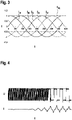
- figure 3 shows current curves, here the phase currents, which are generated with a rotating electrical machine and a sinusoidal phase voltage specification.
- a current I is plotted against time t.
- the individual phase currents I A , I B , I C , I D and I E can be combined to form a space vector.
- the known Clarke and Park transformations are used for this.
- figure 4 shows the phase voltage of a phase for the transition between PWM control and block control or block operation.
- voltage U and current I are plotted against time t. It can be seen from the course of the current that there is no longer any regulation based on the phase current.
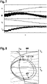
- the current operating point B of the electrical machine is shown in the current locus curve. This operating point results from the current vector or the current I dq and the voltage vector, which indicates the voltage U dq and the phase-to-phase flux ⁇ dq .
- the operating point is the common end of the vectors for the current I dq and the linked flux ⁇ dq .
- the operating point B can only be shifted on the so-called voltage circuit, designated 410 here.
- the voltage circuit 410 represents a maximum possible voltage (or after conversion, the maximum possible phase-to-phase flux), which is used continuously in block operation d-inductance and can thus be shifted by varying the excitation current if the machine is separately excited.
- phase angle (and thus the pre-commutation angle) a can theoretically move between 90° and 180° for motor operation and between 0° and 90° for generator operation.
- phase angle is not at the specified limits, but deviates due to the reluctance torque, the stator resistance and losses. This can be confirmed, for example, by measurements.
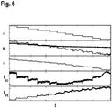
- FIG 6 a measurement for generator operation is shown.
- the phase angle or pre-commutation angle a, the torque M (two different types of measurement, one measured physically and one estimated internally), the efficiency ⁇ , the generated DC current I dc and the phase current I dq are each shown over time t.
- figure 7 a further measurement for engine operation is shown. Compared to figure 6 however, the phase current is not shown here.
- the precommutation angle ⁇ was increased here from 2.55 rad. In this case, the set torque drops from the drawn vertical line despite an increase in the phase angle. The efficiency decreases, the required DC current increases. The tilting angle and thus the stability limit are thus exceeded.
- ⁇ Gr indicates the maximum adjustable phase angle or pre-commutation angle, ie 0° or 180°, as in relation to FIG Figures 5a and 5b already explained.
- the tilting angles 420 and 421 can also be seen again.
- these tilt angles can now be determined in real time or online and thus achieve a larger DC current with a smaller braking torque and smaller phase currents in generator operation.
- the maximum torque is increased and the phase currents at the maximum point are reduced.
- this method increases the dynamics of a controller with block control, since the control range is reduced and instability behind the tilt angle is avoided.
- phase currents and phase voltages are also denoted by lower case letters.
- the flip angle can be calculated by locating the point with the highest magnitude DC current on the voltage ellipse according to figure 8 seeks.
- Rs indicates the stator resistance, ⁇ el the electrical angular frequency, ⁇ R ⁇ tor the excitation flux linkage and ⁇ ⁇ the leakage flux resulting from rotor magnets between the claws of the claw-pole machine.
- I DC 5 2 u DC R s 2 + ⁇ electrical 2 ⁇ L i.e ⁇ L q ( R s and dq 2 + and i.e ⁇ ⁇ electrical 2 L q ⁇ R + ⁇ electrical ⁇ ⁇ R s + and i.e and q ⁇ electrical L q ⁇ L i.e + and q ⁇ R s ⁇ electrical ⁇ R ⁇ ⁇ electrical 2 L i.e ⁇ ⁇
- the calculation includes both the dependency on the stator resistance and the saturation properties of the parameters of the electrical machine.
- the saturation properties are represented by the dependency of the parameters on the phase currents I d , I q and the excitation current I ex .
- L i.e ⁇ i i.e i q i except
- L q ⁇ i i.e i q i except
- ⁇ rotor ⁇ i ex i q i i.e
- the calculation must be carried out iteratively so that the current parameters that apply during operation are always used as a basis.
- phase currents denoted here by I A...E
- the excitation current I ex are measured, and the parameters P at the current operating point are determined from the measured phase currents.
- the parameters can include the already mentioned parameters d-inductance L d , q-inductance L q , the excitation flux linkage ⁇ R ⁇ tor and the leakage flux ⁇ ⁇ .
- the current stator resistance Rs is calculated as a function of the temperature T.
- the maximum and minimum pre-commutation angles ⁇ max and ⁇ min are calculated , which are then included in the regulation.
- the pre-commutation angle can then be determined there and the phase voltage U dq calculated, which in turn is converted into the phase voltages U A...E for the windings.
Landscapes
- Engineering & Computer Science (AREA)
- Power Engineering (AREA)
- Control Of Ac Motors In General (AREA)
- Control Of Motors That Do Not Use Commutators (AREA)
Claims (10)
- Procédé pour faire fonctionner une machine électrique (100) avec une sélection de blocs, caractérisé en ce que dans le cadre d'une régulation d'un couple (M) de la machine électrique, un angle de pré-commutation (α) est réglé de sorte que celui-ci ne franchit pas un angle de décrochage (420, 421) pour un mode moteur et/ou un mode générateur, dans lequel l'angle de décrochage (420, 421) pour le mode moteur et/ou le mode générateur est déterminé de manière itérative pendant le fonctionnement.
- Procédé selon la revendication 1, dans lequel l'angle de décrochage (420, 421) pour le mode moteur et/ou le mode générateur pendant le fonctionnement est déterminé de manière itérative en utilisant une tension réglable maximale actuelle (Udc), une fréquence angulaire actuelle (ωel) de la machine électrique, à partir de paramètres (P) de la machine électrique et d'un courant de phase admissible maximal.
- Procédé selon la revendication 2, dans lequel au moins un flux enchaîné et/ou au moins une inductance de la machine électrique (100) sont utilisés comme paramètres (P) de la machine électrique.
- Procédé selon la revendication 2 ou 3, dans lequel les paramètres (P) de la machine électrique sont déterminés sur la base d'une valeur q d'un courant de phase (Iq) et/ou d'une valeur d d'un courant de phase (Id) et/ou d'un courant d'excitation (Iex).
- Procédé selon la revendication 4, dans lequel la valeur q du courant de phase (Iq) et/ou la valeur d du courant de phase (Id) sont déterminées sur la base de courants de phase mesurés (IA, IB, IC, ID, IE) de la machine électrique.
- Procédé selon l'une des revendications précédentes, dans lequel l'angle de décrochage (420, 421) pour le mode moteur et/ou le mode générateur pendant le fonctionnement est déterminé de manière itérative en utilisant une température actuelle (T) de la machine électrique.
- Procédé selon l'une des revendications précédentes, dans lequel l'angle de pré-commutation (α) est réglé en le régulant dans le cadre d'une régulation en cascade.
- Système constitué d'une machine électrique comportant des moyens pour mesurer des courants de phase (IA, IB, IC, ID, IE) et une unité de calcul (140) configurée pour mettre en œuvre un procédé selon l'une des revendications précédentes.
- Programme informatique qui permet à une unité de calcul (140) d'un système selon la revendication 8 de mettre en œuvre un procédé selon l'une des revendications 1 à 7, lorsqu'il est exécuté sur l'unité de calcul (140).
- Support de mémoire lisible par machine sur lequel est stocké un programme informatique selon la revendication 9.
Applications Claiming Priority (2)
| Application Number | Priority Date | Filing Date | Title |
|---|---|---|---|
| DE102017217912.0A DE102017217912A1 (de) | 2017-10-09 | 2017-10-09 | Verfahren zum Betreiben einer elektrischen Maschine |
| PCT/EP2018/071589 WO2019072440A1 (fr) | 2017-10-09 | 2018-08-09 | Procédé pour faire fonctionner une machine électrique |
Publications (3)
| Publication Number | Publication Date |
|---|---|
| EP3695508A1 EP3695508A1 (fr) | 2020-08-19 |
| EP3695508B1 true EP3695508B1 (fr) | 2022-07-13 |
| EP3695508B8 EP3695508B8 (fr) | 2022-08-17 |
Family
ID=63168419
Family Applications (1)
| Application Number | Title | Priority Date | Filing Date |
|---|---|---|---|
| EP18753159.5A Active EP3695508B8 (fr) | 2017-10-09 | 2018-08-09 | Procédé pour faire fonctionner une machine électrique |
Country Status (6)
| Country | Link |
|---|---|
| EP (1) | EP3695508B8 (fr) |
| CN (1) | CN111264025B (fr) |
| DE (1) | DE102017217912A1 (fr) |
| ES (1) | ES2928294T3 (fr) |
| HU (1) | HUE060278T2 (fr) |
| WO (1) | WO2019072440A1 (fr) |
Families Citing this family (1)
| Publication number | Priority date | Publication date | Assignee | Title |
|---|---|---|---|---|
| CN115149851A (zh) | 2021-03-31 | 2022-10-04 | 华润微集成电路(无锡)有限公司 | 用于实现电机超前滞后换相的电路结构 |
Family Cites Families (7)
| Publication number | Priority date | Publication date | Assignee | Title |
|---|---|---|---|---|
| US7436139B2 (en) * | 2003-01-29 | 2008-10-14 | Matra Manufacturing & Services Sas | Phase advance angle optimization for brushless motor control |
| DE102005045401A1 (de) * | 2005-09-23 | 2007-03-29 | Robert Bosch Gmbh | Verfahren zur Stromversorgung eines über eine Halbleiter-Leistungsendstufe elektronisch kommutierbaren Gleichstrommotors |
| DE102006021489A1 (de) * | 2006-05-09 | 2007-11-15 | Robert Bosch Gmbh | Elektrische Maschine |
| JP2008125245A (ja) * | 2006-11-13 | 2008-05-29 | Matsushita Electric Ind Co Ltd | モータ駆動装置 |
| JP5167717B2 (ja) * | 2007-08-08 | 2013-03-21 | 日本精工株式会社 | モータ駆動制御装置及びモータ駆動制御装置を使用した電動パワーステアリング装置 |
| JP5665383B2 (ja) * | 2010-06-16 | 2015-02-04 | キヤノン株式会社 | モータ制御装置及び制御方法 |
| DE102015216279A1 (de) * | 2015-08-26 | 2017-03-02 | Robert Bosch Gmbh | Verfahren zum Ermitteln eines Vorkommutierungswinkels einer elektrischen Maschine |
-
2017
- 2017-10-09 DE DE102017217912.0A patent/DE102017217912A1/de active Pending
-
2018
- 2018-08-09 WO PCT/EP2018/071589 patent/WO2019072440A1/fr unknown
- 2018-08-09 ES ES18753159T patent/ES2928294T3/es active Active
- 2018-08-09 CN CN201880065430.8A patent/CN111264025B/zh active Active
- 2018-08-09 EP EP18753159.5A patent/EP3695508B8/fr active Active
- 2018-08-09 HU HUE18753159A patent/HUE060278T2/hu unknown
Also Published As
| Publication number | Publication date |
|---|---|
| CN111264025B (zh) | 2024-02-23 |
| EP3695508A1 (fr) | 2020-08-19 |
| ES2928294T3 (es) | 2022-11-16 |
| DE102017217912A1 (de) | 2019-04-11 |
| EP3695508B8 (fr) | 2022-08-17 |
| CN111264025A (zh) | 2020-06-09 |
| WO2019072440A1 (fr) | 2019-04-18 |
| HUE060278T2 (hu) | 2023-02-28 |
Similar Documents
| Publication | Publication Date | Title |
|---|---|---|
| DE60036665T3 (de) | Verfahren und Vorrichtung zur Bestromung der Statorwindungen einer drehenden elektrischen Maschine | |
| DE102005042777B4 (de) | Motorantriebssteuerungsgerät, Motorantriebssteuerungsverfahren und zugehöriges Programm | |
| DE112010000463B4 (de) | Steuerungsvorrichtung für eine Elektromotorantriebsvorrichtung | |
| DE112010003370B4 (de) | Steuerungsvorrichtung für eine Elektromotorantriebsvorrichtung | |
| DE10120639B4 (de) | Steuersystem für einen Permanentmagnetmotor | |
| DE112012000830T5 (de) | Antriebssystem für rotierende elektrische Maschine | |
| DE112011100226T5 (de) | Steuerungsvorrichtung einer Motorantriebsvorrichtung | |
| DE112011100096T5 (de) | Steuerungsvorrichtung einer Motorantriebsvorrichtung | |
| DE102011000949A1 (de) | Steuervorrichtung für eine drehende elektrische Maschine | |
| DE102008034541A1 (de) | Steuerungseinrichtung zum Antreiben eines bürstenlosen Gleichstrommotors | |
| EP2192682B1 (fr) | Contrôle d'une machine synchrone à aimants permanents | |
| DE102013203505A1 (de) | Verfahren, Systeme und eine Vorrichtung zur Erzeugung von Spannungsbefehlsignalen zur Steuerung eines Betriebes einer elektrischen Maschine | |
| DE112016000455T5 (de) | Steuerungsgerät für eine rotierende elektrische Maschine | |
| WO2012159843A2 (fr) | Procédé permettant de faire fonctionner un moteur électrique dans un véhicule à moteur | |
| EP3695508B1 (fr) | Procédé pour faire fonctionner une machine électrique | |
| DE102015224586A1 (de) | Arbeitspunktbestimmung einer Synchronmaschine | |
| WO2015014701A2 (fr) | Procédé de mise sous tension et de mise hors tension d'un moteur électrique à n phases dans un véhicule automobile | |
| DE102013223624A1 (de) | Verfahren zum Ansteuern einer elektrischen Maschine | |
| EP3695509B1 (fr) | Procédé pour effectuer un changement entre une commande par bloc et une commande par mli d'une machine électrique | |
| DE112021002186T5 (de) | Motorsteuerungseinrichtung, mechatronikeinheit, leistungserzeugungssystem,hochsetzstellersystem und elektroverkehrsmittelsystem | |
| EP3685503B1 (fr) | Procédé de détermination d'un couple maximal réglable d'une machine électrique | |
| EP3685504B1 (fr) | Procédé pour faire fonctionner une machine électrique à excitation séparée | |
| EP3292628B1 (fr) | Procédé de mise en marche d'une machine électrique polyphasée dans un véhicule automobile | |
| DE112018005734T5 (de) | Motorsteuervorrichtung und Motorsteuerverfahren | |
| DE112018000391T5 (de) | Steuerungssystem für eine elektrische Rotationsmaschine |
Legal Events
| Date | Code | Title | Description |
|---|---|---|---|
| STAA | Information on the status of an ep patent application or granted ep patent |
Free format text: STATUS: UNKNOWN |
|
| STAA | Information on the status of an ep patent application or granted ep patent |
Free format text: STATUS: THE INTERNATIONAL PUBLICATION HAS BEEN MADE |
|
| PUAI | Public reference made under article 153(3) epc to a published international application that has entered the european phase |
Free format text: ORIGINAL CODE: 0009012 |
|
| STAA | Information on the status of an ep patent application or granted ep patent |
Free format text: STATUS: REQUEST FOR EXAMINATION WAS MADE |
|
| 17P | Request for examination filed |
Effective date: 20200507 |
|
| AK | Designated contracting states |
Kind code of ref document: A1 Designated state(s): AL AT BE BG CH CY CZ DE DK EE ES FI FR GB GR HR HU IE IS IT LI LT LU LV MC MK MT NL NO PL PT RO RS SE SI SK SM TR |
|
| AX | Request for extension of the european patent |
Extension state: BA ME |
|
| DAV | Request for validation of the european patent (deleted) | ||
| DAX | Request for extension of the european patent (deleted) | ||
| REG | Reference to a national code |
Ref country code: DE Ref legal event code: R079 Ref document number: 502018010150 Country of ref document: DE Free format text: PREVIOUS MAIN CLASS: H02P0006100000 Ipc: H02P0021220000 |
|
| GRAP | Despatch of communication of intention to grant a patent |
Free format text: ORIGINAL CODE: EPIDOSNIGR1 |
|
| STAA | Information on the status of an ep patent application or granted ep patent |
Free format text: STATUS: GRANT OF PATENT IS INTENDED |
|
| RIC1 | Information provided on ipc code assigned before grant |
Ipc: H02P 21/22 20160101AFI20210622BHEP Ipc: H02P 25/22 20060101ALI20210622BHEP |
|
| INTG | Intention to grant announced |
Effective date: 20210728 |
|
| GRAJ | Information related to disapproval of communication of intention to grant by the applicant or resumption of examination proceedings by the epo deleted |
Free format text: ORIGINAL CODE: EPIDOSDIGR1 |
|
| STAA | Information on the status of an ep patent application or granted ep patent |
Free format text: STATUS: REQUEST FOR EXAMINATION WAS MADE |
|
| INTC | Intention to grant announced (deleted) | ||
| GRAP | Despatch of communication of intention to grant a patent |
Free format text: ORIGINAL CODE: EPIDOSNIGR1 |
|
| STAA | Information on the status of an ep patent application or granted ep patent |
Free format text: STATUS: GRANT OF PATENT IS INTENDED |
|
| INTG | Intention to grant announced |
Effective date: 20220127 |
|
| GRAS | Grant fee paid |
Free format text: ORIGINAL CODE: EPIDOSNIGR3 |
|
| GRAA | (expected) grant |
Free format text: ORIGINAL CODE: 0009210 |
|
| STAA | Information on the status of an ep patent application or granted ep patent |
Free format text: STATUS: THE PATENT HAS BEEN GRANTED |
|
| AK | Designated contracting states |
Kind code of ref document: B1 Designated state(s): AL AT BE BG CH CY CZ DE DK EE ES FI FR GB GR HR HU IE IS IT LI LT LU LV MC MK MT NL NO PL PT RO RS SE SI SK SM TR |
|
| REG | Reference to a national code |
Ref country code: CH Ref legal event code: EP |
|
| REG | Reference to a national code |
Ref country code: CH Ref legal event code: PK Free format text: BERICHTIGUNG B8 |
|
| RAP4 | Party data changed (patent owner data changed or rights of a patent transferred) |
Owner name: SEG AUTOMOTIVE GERMANY GMBH Owner name: ROBERT BOSCH GMBH |
|
| REG | Reference to a national code |
Ref country code: DE Ref legal event code: R096 Ref document number: 502018010150 Country of ref document: DE |
|
| REG | Reference to a national code |
Ref country code: AT Ref legal event code: REF Ref document number: 1504791 Country of ref document: AT Kind code of ref document: T Effective date: 20220815 |
|
| REG | Reference to a national code |
Ref country code: IE Ref legal event code: FG4D Free format text: LANGUAGE OF EP DOCUMENT: GERMAN |
|
| REG | Reference to a national code |
Ref country code: LT Ref legal event code: MG9D |
|
| REG | Reference to a national code |
Ref country code: NL Ref legal event code: MP Effective date: 20220713 Ref country code: ES Ref legal event code: FG2A Ref document number: 2928294 Country of ref document: ES Kind code of ref document: T3 Effective date: 20221116 |
|
| PG25 | Lapsed in a contracting state [announced via postgrant information from national office to epo] |
Ref country code: SE Free format text: LAPSE BECAUSE OF FAILURE TO SUBMIT A TRANSLATION OF THE DESCRIPTION OR TO PAY THE FEE WITHIN THE PRESCRIBED TIME-LIMIT Effective date: 20220713 Ref country code: RS Free format text: LAPSE BECAUSE OF FAILURE TO SUBMIT A TRANSLATION OF THE DESCRIPTION OR TO PAY THE FEE WITHIN THE PRESCRIBED TIME-LIMIT Effective date: 20220713 Ref country code: PT Free format text: LAPSE BECAUSE OF FAILURE TO SUBMIT A TRANSLATION OF THE DESCRIPTION OR TO PAY THE FEE WITHIN THE PRESCRIBED TIME-LIMIT Effective date: 20221114 Ref country code: NO Free format text: LAPSE BECAUSE OF FAILURE TO SUBMIT A TRANSLATION OF THE DESCRIPTION OR TO PAY THE FEE WITHIN THE PRESCRIBED TIME-LIMIT Effective date: 20221013 Ref country code: NL Free format text: LAPSE BECAUSE OF FAILURE TO SUBMIT A TRANSLATION OF THE DESCRIPTION OR TO PAY THE FEE WITHIN THE PRESCRIBED TIME-LIMIT Effective date: 20220713 Ref country code: LV Free format text: LAPSE BECAUSE OF FAILURE TO SUBMIT A TRANSLATION OF THE DESCRIPTION OR TO PAY THE FEE WITHIN THE PRESCRIBED TIME-LIMIT Effective date: 20220713 Ref country code: LT Free format text: LAPSE BECAUSE OF FAILURE TO SUBMIT A TRANSLATION OF THE DESCRIPTION OR TO PAY THE FEE WITHIN THE PRESCRIBED TIME-LIMIT Effective date: 20220713 Ref country code: FI Free format text: LAPSE BECAUSE OF FAILURE TO SUBMIT A TRANSLATION OF THE DESCRIPTION OR TO PAY THE FEE WITHIN THE PRESCRIBED TIME-LIMIT Effective date: 20220713 |
|
| PG25 | Lapsed in a contracting state [announced via postgrant information from national office to epo] |
Ref country code: PL Free format text: LAPSE BECAUSE OF FAILURE TO SUBMIT A TRANSLATION OF THE DESCRIPTION OR TO PAY THE FEE WITHIN THE PRESCRIBED TIME-LIMIT Effective date: 20220713 Ref country code: IS Free format text: LAPSE BECAUSE OF FAILURE TO SUBMIT A TRANSLATION OF THE DESCRIPTION OR TO PAY THE FEE WITHIN THE PRESCRIBED TIME-LIMIT Effective date: 20221113 Ref country code: HR Free format text: LAPSE BECAUSE OF FAILURE TO SUBMIT A TRANSLATION OF THE DESCRIPTION OR TO PAY THE FEE WITHIN THE PRESCRIBED TIME-LIMIT Effective date: 20220713 Ref country code: GR Free format text: LAPSE BECAUSE OF FAILURE TO SUBMIT A TRANSLATION OF THE DESCRIPTION OR TO PAY THE FEE WITHIN THE PRESCRIBED TIME-LIMIT Effective date: 20221014 |
|
| REG | Reference to a national code |
Ref country code: HU Ref legal event code: AG4A Ref document number: E060278 Country of ref document: HU |
|
| REG | Reference to a national code |
Ref country code: CH Ref legal event code: PL |
|
| REG | Reference to a national code |
Ref country code: DE Ref legal event code: R097 Ref document number: 502018010150 Country of ref document: DE |
|
| PG25 | Lapsed in a contracting state [announced via postgrant information from national office to epo] |
Ref country code: SM Free format text: LAPSE BECAUSE OF FAILURE TO SUBMIT A TRANSLATION OF THE DESCRIPTION OR TO PAY THE FEE WITHIN THE PRESCRIBED TIME-LIMIT Effective date: 20220713 Ref country code: RO Free format text: LAPSE BECAUSE OF FAILURE TO SUBMIT A TRANSLATION OF THE DESCRIPTION OR TO PAY THE FEE WITHIN THE PRESCRIBED TIME-LIMIT Effective date: 20220713 Ref country code: MC Free format text: LAPSE BECAUSE OF FAILURE TO SUBMIT A TRANSLATION OF THE DESCRIPTION OR TO PAY THE FEE WITHIN THE PRESCRIBED TIME-LIMIT Effective date: 20220713 Ref country code: LU Free format text: LAPSE BECAUSE OF NON-PAYMENT OF DUE FEES Effective date: 20220809 Ref country code: LI Free format text: LAPSE BECAUSE OF NON-PAYMENT OF DUE FEES Effective date: 20220831 Ref country code: DK Free format text: LAPSE BECAUSE OF FAILURE TO SUBMIT A TRANSLATION OF THE DESCRIPTION OR TO PAY THE FEE WITHIN THE PRESCRIBED TIME-LIMIT Effective date: 20220713 Ref country code: CZ Free format text: LAPSE BECAUSE OF FAILURE TO SUBMIT A TRANSLATION OF THE DESCRIPTION OR TO PAY THE FEE WITHIN THE PRESCRIBED TIME-LIMIT Effective date: 20220713 Ref country code: CH Free format text: LAPSE BECAUSE OF NON-PAYMENT OF DUE FEES Effective date: 20220831 |
|
| REG | Reference to a national code |
Ref country code: BE Ref legal event code: MM Effective date: 20220831 |
|
| PLBE | No opposition filed within time limit |
Free format text: ORIGINAL CODE: 0009261 |
|
| STAA | Information on the status of an ep patent application or granted ep patent |
Free format text: STATUS: NO OPPOSITION FILED WITHIN TIME LIMIT |
|
| PG25 | Lapsed in a contracting state [announced via postgrant information from national office to epo] |
Ref country code: SK Free format text: LAPSE BECAUSE OF FAILURE TO SUBMIT A TRANSLATION OF THE DESCRIPTION OR TO PAY THE FEE WITHIN THE PRESCRIBED TIME-LIMIT Effective date: 20220713 Ref country code: EE Free format text: LAPSE BECAUSE OF FAILURE TO SUBMIT A TRANSLATION OF THE DESCRIPTION OR TO PAY THE FEE WITHIN THE PRESCRIBED TIME-LIMIT Effective date: 20220713 |
|
| 26N | No opposition filed |
Effective date: 20230414 |
|
| GBPC | Gb: european patent ceased through non-payment of renewal fee |
Effective date: 20221013 |
|
| PG25 | Lapsed in a contracting state [announced via postgrant information from national office to epo] |
Ref country code: AL Free format text: LAPSE BECAUSE OF FAILURE TO SUBMIT A TRANSLATION OF THE DESCRIPTION OR TO PAY THE FEE WITHIN THE PRESCRIBED TIME-LIMIT Effective date: 20220713 |
|
| PG25 | Lapsed in a contracting state [announced via postgrant information from national office to epo] |
Ref country code: IE Free format text: LAPSE BECAUSE OF NON-PAYMENT OF DUE FEES Effective date: 20220809 |
|
| PG25 | Lapsed in a contracting state [announced via postgrant information from national office to epo] |
Ref country code: SI Free format text: LAPSE BECAUSE OF FAILURE TO SUBMIT A TRANSLATION OF THE DESCRIPTION OR TO PAY THE FEE WITHIN THE PRESCRIBED TIME-LIMIT Effective date: 20220713 |
|
| PG25 | Lapsed in a contracting state [announced via postgrant information from national office to epo] |
Ref country code: BE Free format text: LAPSE BECAUSE OF NON-PAYMENT OF DUE FEES Effective date: 20220831 |
|
| PG25 | Lapsed in a contracting state [announced via postgrant information from national office to epo] |
Ref country code: GB Free format text: LAPSE BECAUSE OF NON-PAYMENT OF DUE FEES Effective date: 20221013 |
|
| PGFP | Annual fee paid to national office [announced via postgrant information from national office to epo] |
Ref country code: IT Payment date: 20230818 Year of fee payment: 6 Ref country code: ES Payment date: 20230901 Year of fee payment: 6 |
|
| PGFP | Annual fee paid to national office [announced via postgrant information from national office to epo] |
Ref country code: HU Payment date: 20230804 Year of fee payment: 6 Ref country code: FR Payment date: 20230817 Year of fee payment: 6 Ref country code: DE Payment date: 20230821 Year of fee payment: 6 |
|
| PG25 | Lapsed in a contracting state [announced via postgrant information from national office to epo] |
Ref country code: CY Free format text: LAPSE BECAUSE OF FAILURE TO SUBMIT A TRANSLATION OF THE DESCRIPTION OR TO PAY THE FEE WITHIN THE PRESCRIBED TIME-LIMIT Effective date: 20220713 |