EP3693723A2 - Sonde zur messung der veränderung von werkstoffen durch gasströme in dampferzeugern oder anderen verbrennungsanlagen - Google Patents
Sonde zur messung der veränderung von werkstoffen durch gasströme in dampferzeugern oder anderen verbrennungsanlagen Download PDFInfo
- Publication number
- EP3693723A2 EP3693723A2 EP20000048.7A EP20000048A EP3693723A2 EP 3693723 A2 EP3693723 A2 EP 3693723A2 EP 20000048 A EP20000048 A EP 20000048A EP 3693723 A2 EP3693723 A2 EP 3693723A2
- Authority
- EP
- European Patent Office
- Prior art keywords
- temperature control
- material sample
- control medium
- probe
- heat sink
- Prior art date
- Legal status (The legal status is an assumption and is not a legal conclusion. Google has not performed a legal analysis and makes no representation as to the accuracy of the status listed.)
- Granted
Links
Images


Classifications
-
- G—PHYSICS
- G01—MEASURING; TESTING
- G01N—INVESTIGATING OR ANALYSING MATERIALS BY DETERMINING THEIR CHEMICAL OR PHYSICAL PROPERTIES
- G01N17/00—Investigating resistance of materials to the weather, to corrosion, or to light
- G01N17/04—Corrosion probes
- G01N17/043—Coupons
- G01N17/046—Means for supporting or introducing coupons
-
- G—PHYSICS
- G01—MEASURING; TESTING
- G01K—MEASURING TEMPERATURE; MEASURING QUANTITY OF HEAT; THERMALLY-SENSITIVE ELEMENTS NOT OTHERWISE PROVIDED FOR
- G01K1/00—Details of thermometers not specially adapted for particular types of thermometer
- G01K1/16—Special arrangements for conducting heat from the object to the sensitive element
-
- G—PHYSICS
- G01—MEASURING; TESTING
- G01K—MEASURING TEMPERATURE; MEASURING QUANTITY OF HEAT; THERMALLY-SENSITIVE ELEMENTS NOT OTHERWISE PROVIDED FOR
- G01K13/00—Thermometers specially adapted for specific purposes
- G01K13/02—Thermometers specially adapted for specific purposes for measuring temperature of moving fluids or granular materials capable of flow
-
- G—PHYSICS
- G01—MEASURING; TESTING
- G01K—MEASURING TEMPERATURE; MEASURING QUANTITY OF HEAT; THERMALLY-SENSITIVE ELEMENTS NOT OTHERWISE PROVIDED FOR
- G01K13/00—Thermometers specially adapted for specific purposes
- G01K13/02—Thermometers specially adapted for specific purposes for measuring temperature of moving fluids or granular materials capable of flow
- G01K13/024—Thermometers specially adapted for specific purposes for measuring temperature of moving fluids or granular materials capable of flow of moving gases
-
- G—PHYSICS
- G01—MEASURING; TESTING
- G01N—INVESTIGATING OR ANALYSING MATERIALS BY DETERMINING THEIR CHEMICAL OR PHYSICAL PROPERTIES
- G01N3/00—Investigating strength properties of solid materials by application of mechanical stress
- G01N3/56—Investigating resistance to wear or abrasion
- G01N3/567—Investigating resistance to wear or abrasion by submitting the specimen to the action of a fluid or of a fluidised material, e.g. cavitation, jet abrasion
Definitions
- the invention relates to a probe for measuring the change in materials due to gas flows in steam generators or other combustion systems, the probe having a temperature control medium inflow channel, a temperature control medium outflow channel, a material sample receptacle for a material sample and a heat sink, and the heat sink arranged on an inside of the material sample facing away from the gas flows and is thermally connected to it.
- the inner walls of a steam generator and other combustion systems, reactors, converters, heat exchangers etc. in power plants and the steel and chemical industry etc. are exposed to high temperatures and aggressive exhaust and flue gases, or specific chemical fluids (gaseous or liquid, loaded with particles or multi-phase). Corrosive salts and inert ashes are deposited on the surfaces of the interior walls from the waste gases and flue gases, these deposits then leading to corrosion damage to the interior walls. In other plants, hard particles are thrown against the inner walls and removed by abrasion, or cover layers with the salts and ashes formed by corrosion are removed by erosion. Understanding the temperature-dependent corrosion, abrasion and erosion mechanisms is necessary to optimize the materials used for the interior walls. For this purpose, probes with material samples to be tested are exposed in the running steam generator. The probes are designed so that the material samples can be cooled in a defined manner.
- the temperature control medium flows through the channel in an uncontrolled manner, the cross section of which is also narrowed by cables and associated cable ties for temperature measurement within the material sample, a turbulent flow is formed between the material sample and the fluid line. This prevents a uniform cooling of the material sample over its entire area, as well as during the test.
- the properties of the coating that forms on the outside of the material sample during the test either change continuously or discontinuously (coating thickness, density, thermal conductivity, endothermic or exothermic chemical reactions in the coating, etc.). Accordingly, the heat transfer from the waste gas or flue gas changes into the covering and through it to the material sample cooled from the inside.
- the temperature of the material sample can be kept relatively constant at a single control point, but the distance between the isogrades of the constant temperature gradient actually aimed for will either shrink or spread, so that there is no continuous temperature gradient in or on the material sample can adjust.
- the temperatures on the inside of the material sample cannot always correlate with the temperatures on the outside of the tube, i.e. higher or lower temperatures uncontrollably and inconsistently change the intended mapping of the corrosion, abrasion and erosion processes and the behavior of the material .
- This corrosion probe consists of a lance with a lance head.
- the lance head serves as a holder for a circular material sample which can be introduced into a steam generator with the lance.
- the lance is formed from an inner tube, a middle tube and an outer tube.
- the inner tube serves as a cable guide for the electrical connection of the subsegments of the material sample.
- a temperature control medium can be introduced into the channel between the inner tube and the central tube via a first connection. The temperature control medium flows in this channel up to the lance head, is deflected there and flows via the channel between the center tube and the outer tube to the second connection, where it leaves the lance.
- the lance head with the attached material sample is cooled by the temperature control medium flow.
- a heat sink is provided at the transition between the two channels to improve the heat flow in the lance head.
- This heat sink has fins or teeth which extend into the temperature control medium flow so that the heat transfer between the temperature control medium and the lance head and thus to the material sample attached to the lance head is improved.
- the heat sink is preferably made of copper and ensures that a sufficiently high heat flow from the lance head can be discharged. Due to the channel between the inner tube and the central tube, which is annular in cross section, this solution also has the disadvantage that the temperature control medium is guided to the lance head in an uncontrolled manner and an undesired temperature gradient is thus established in the cross section along the ring.
- the object of the invention is therefore to create a probe in which a homogeneous temperature control of the material sample is ensured.
- the thermal energy that is transferred to the material sample via the gas flows is evenly transported away from the heat sink over the entire area of the inside.
- the heat energy from the heat sink is dissipated by the temperature control agent.
- the uniform cooling of the material sample also achieves a homogeneous heat flow along the coating growing on the side of the material sample facing the gas flows.
- the formation of the heat sink from a solid heat conducting part and cooling fins has the advantage that the heat conducting part can be adapted to the shape of the inside of the material sample and thus an optimal heat transfer from the material sample to the heat conducting part is made possible.
- the cooling fins offer a large surface when the temperature control medium flows around them, so that the thermal energy absorbed by the heat conducting part can be completely dissipated by the temperature control medium.
- the temperature sensors arranged in the heat-conducting part in the receptacles and applied to the inside of the material sample can be used to regulate the temperature medium inflow and thus the temperature of the material sample.
- These temperature sensors can be thermocouples, for example.
- the temperatures recorded by the temperature sensors can be logged.
- the probe according to the invention can be used both on flat wall surfaces and on curved wall surfaces (e.g. wall surface of an inner pipe wall)
- Fig. 1 shows a perspective view of an embodiment of a probe 1 according to the invention for measuring the change in materials due to gas flows in a steam generator.
- the probe 1 has a housing 2, one end face 3 of the probe 1 facing the gas flows when used in the steam generator and thus being exposed to these gas flows.
- a recess for receiving two material samples 4 is provided on this end face 3.
- the material samples 4 each have a measurement area 5, the material samples 4 in each measurement area 5 having a surface curved in the direction of gas flows.
- FIG. 8 is a side view of the embodiment according to FIG Fig. 1 .
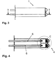
- Fig. 3 represents a side view rotated by 90 ° Fig. 2 represent.
- Fig. 4 shows a sectional view along the section line AA according to Fig. 2 .
- Two temperature control medium supply channels 6 are led into the housing 2, these temperature control medium supply channels 6 being designed as pipelines.
- a temperature control medium can be guided in the direction of material sample 4. The material sample is thus exposed to the flow parallel to the longitudinal axis of the housing.
- Fig. 5 shows a sectional view along the section line BB according to Fig. 3 .
- a temperature control medium outflow channel 7 is formed by an inner surface of the housing 2 of the probe 1 and an outer jacket surface of the pipeline 6.
- FIG. 6 is a detailed view of section C according to Fig. 4 to see.
- a heat sink 9 is arranged on an inside 8 of the material sample 4 facing away from the gas flows.
- This heat sink 9 is thermally connected to the inside 8 of the material sample 4 over the entire surface in the respective measuring area 5.
- the thermal connection is achieved in that the cooling body 9 in the measuring area rests over the entire surface on the inside 8 of the measuring area 5.
- the thermal connection could, however, also take place via a heat coupling medium (for example heat conducting paste) which is thermally connected over the entire surface to the inside 8 of the measuring area 5 of the material sample 4 and the heat sink 9.
- a heat coupling medium for example heat conducting paste
- each temperature control medium inflow channel 6 facing the heat sink 9 is designed with a nozzle arrangement 10 that tapers in the direction of flow, a nozzle opening 11 of this nozzle arrangement 10 being oriented in the direction of the heat sink 9.
- the cooling body 9 has a solid heat-conducting part 9a on a side facing the inner side 8 of the material sample 4 and cooling ribs 9b on a side facing the nozzle opening 11.
- the cooling fins 9b are aligned in the direction of the nozzle opening 11.
- the temperature control medium (for example compressed air) supplied via the temperature control medium inflow channel 6 is guided from the nozzle opening 11 in the direction of the cooling fins 9b, with the temperature control medium flow impinging centrally on the heat sink 9 in the embodiment shown.
- the coolant flows around the cooling ribs 9b and is guided by them in the direction of the temperature control medium outflow channel 7, via which the temperature control medium leaves the housing 2 against the flow direction of the temperature control medium inflow channel 6.
- the temperature control medium outflow channel 7 serves to return the temperature control medium from both temperature control medium inflow channels 6.
- separate temperature control medium outflow channels 7 can also be provided for the temperature control medium supplied via both temperature control medium inflow channels 6.
- a partition arranged in the longitudinal direction of the housing can be used for this. Such a partition is not shown.
- the heat conducting part 9a of the cooling body 9 is fitted into the curvature of the material sample 4, so that a full-surface thermal transition is ensured in the respective measuring area 5.
- the heat conducting part 9a is made of copper and the cooling fins 9b are made of aluminum.
- three receptacles 12 are provided for temperature sensors, which rest on the inside 8 of the material sample 4 on the relevant measuring area 5 and are therefore fixed in this position. The temperature sensors themselves are not shown.
- the temperature control medium supply channels 6 can be regulated independently of one another in the embodiment shown. In this way, two identical material samples 4 can also be tested at different temperatures, the temperature of the respective material sample preferably being set via the temperature control medium flow density.
- a receptacle for two material samples 4 is provided.
- the invention is not limited to this.
- only one material sample 4 can be provided, in which case only one temperature control medium inflow channel 6 is necessary.
- the probe 1 can also be designed in such a way that more than two material samples 4 can be tested.
- the number of heat sinks 9 and temperature control medium inflow channels 6 must be increased in accordance with the number of material samples 4.
- either a jointly used temperature control medium drainage channel 7 or separate temperature control medium drainage channels 7 can be provided.
- the probe 1 can be designed for four material samples 4, which can then be positioned, for example, in a 2 ⁇ 2 arrangement.
- eight material samples 4 with a 4x2 or 2x4 arrangement are also conceivable, for example.
Landscapes
- Physics & Mathematics (AREA)
- General Physics & Mathematics (AREA)
- Life Sciences & Earth Sciences (AREA)
- Biodiversity & Conservation Biology (AREA)
- Ecology (AREA)
- Environmental & Geological Engineering (AREA)
- Environmental Sciences (AREA)
- Health & Medical Sciences (AREA)
- Chemical & Material Sciences (AREA)
- Analytical Chemistry (AREA)
- Biochemistry (AREA)
- General Health & Medical Sciences (AREA)
- Immunology (AREA)
- Pathology (AREA)
- Investigating Or Analyzing Materials Using Thermal Means (AREA)
- Sampling And Sample Adjustment (AREA)
Abstract
Description
- Die Erfindung betrifft eine Sonde zur Messung der Veränderung von Werkstoffen durch Gasströme in Dampferzeugern oder anderen Verbrennungsanlagen, wobei die Sonde einen Temperiermittelzuflusskanal, einen Temperiermittelabflusskanal, eine Werkstoffprobenaufnahme für eine Werkstoffprobe und einen Kühlkörper aufweist und wobei der Kühlkörper auf einer den Gasströmen abgewandten Innenseite der Werkstoffprobe angeordnet und thermisch mit dieser verbunden ist.
- Die Innenwände eines Dampferzeugers und anderer Verbrennungsanagen, Reaktoren Konverter, Wärmetauscher etc. z.B. in Kraftwerken und der Stahl- und chemischen Industrie etc. sind im Betrieb hohen Temperaturen und aggressiven Ab- und Rauchgasen, oder spezifischen chemischen Fluiden (gasförmig oder flüssig, mit Partikeln beladen oder mehrphasig) ausgesetzt. Aus den Ab- und Rauchgasen lagern sich auf den Oberflächen der Innenwände korrosive Salze und inerte Aschen ab, wobei diese Ablagerungen dann zu einer Schädigung der Innenwände durch Korrosion führen. In anderen Anlagen werden harte Partikel gegen die Innenwände geschleudert und durch Abrasion abgetragen, oder durch Korrosion entstandene Deckschichten mit den Salzen und Aschen werden durch Erosion abgetragen. Für eine Optimierung der für die Innenwände eingesetzten Werkstoffe ist das Verständnis der temperaturabhängigen Korrosions-, Abrasions- und Erosionsmechanismen notwendig. Hierzu werden Sonden mit zu prüfenden Werkstoffproben im laufenden Dampferzeuger exponiert. Die Sonden sind dabei so ausgebildet, dass die Werkstoffproben definiert kühlbar sind.
- Aus dem Stand der Technik sind verschiedene Sonden bekannt. Beispielsweise wird in
DE 10 2013 007 529 B3 eine Vorrichtung zur Messung der Veränderung von Werkstoffen durch Gasströme vorgeschlagen. Diese Vorrichtung weist ein aus dem zu prüfenden Werkstoff gebildetes Außenrohrs als Werkstoffprobe und eine in diesem Rohr axial angeordnete Fluidleitung auf. Das Rohr ist an einer Stirnseite geschlossen. Über die Fluidleitung wird ein Temperiermittel auf die Innenfläche der verschlossenen Stirnseite des Rohrs geleitet, umgelenkt und in dem Kanal zwischen Rohr und Fluidleitung wieder aus dem Rohr herausgeführt. Der Fluidstrom im Kanal kühlt damit den Mantel des Rohrs und wirkt damit der Wärmeeinwirkung durch die Rauchgase entgegen. Durch die zunehmende Erwärmung des Temperiermittels beim Ableiten entsteht auf dem Rohrmantel ein Temperaturgradient, sodass die Korrosion für verschiedene Temperaturregime untersucht werden kann. Da aber das Temperiermittel den Kanal unkontrolliert durchströmt, dessen Querschnitt zudem durch Kabel und zugehörige Kabelbinder der Temperaturmessung innerhalb der Werkstoffprobe verengt wird, bildet sich eine turbulente Strömung zwischen Werkstoffprobe und Fluidleitung aus. Dies verhindert eine gleichmäßige Kühlung der Werkstoffprobe über deren gesamte Fläche, sowie während der Dauer des Tests. Zudem verändern die sich Eigenschaften des Belags, der sich auf der Außenseite der Werkstoffprobe während der Dauer des Tests bildet, entweder stetig oder unstetig (Belagsdicke, -dichte, Wärmeleitfähigkeit, endotherme oder exotherme chemische reaktionen im Belag etc.). Dementsprechend verändert sich der Wärmeübergang vom Ab- oder Rauchgas in den Belag hinein und durch ihn hindurch bis in die von innen gekühlte Werkstoffprobe. Das bedeutet, dass zwar die Temperatur der Werkstoffprobe an einem einzelnen Regelpunkt relativ konstant gehalten werden kann, aber der Abstand der sich danach ausbreitenden Isograden des eigentlich angestrebten, konstanten Temperaturgradienten wird entweder schrumpfen oder sich spreizen, sodass sich kein kontinuierlicher Temperaturgradient in oder auf der Werkstoffprobe einstellen kann. Das bedeutet, dass auch die Temperaturen auf der Innenseite der Werkstoffprobe nicht immer mit den Temperaturen der Außenseite des Rohrs korrelieren können, d.h. höhere oder niedrigere Temperaturen die eigentlich beabsichtigte Abbildung der Korrosions-, Abrasions- und Erosionsprozesse und das Verhalten des Werkstoffs unkontrollierbar und unstetig verändern. -
DE 10 2009 053 719 A1 beschreibt eine Korrsosionssonde zur elektrochemischen Messung der Korrosionsrate. Diese Korrsosionssonde besteht aus einer Lanze mit einem Lanzenkopf. Der Lanzenkopf dient als Halter für eine kreisflächige Werkstoffprobe, die mit der Lanze in einen Dampferzeuger einführbar ist. Die Lanze wird aus einem Innenrohr, einem Mittelrohr und einem Außenrohr gebildet. Das Innenrohr dient als Kabelführung des elektrischen Anschlusses der Teilsegmente der Werkstoffprobe. Über einen ersten Anschluss ist ein Temperiermittel in den Kanal zwischen Innenrohr und Mittelrohr einführbar. In diesem Kanal fließt das Temperiermittel bis zum Lanzenkopf, wird dort umgelenkt und fließt über den Kanal zwischen Mittelrohr und Außenrohr zum zweiten Anschluss, wo es die Lanze verlässt. Durch den Temperiermittelstrom wird der Lanzenkopf mit der daran befestigten Werkstoffprobe gekühlt. Zur Verbesserung des Wärmestroms im Lanzenkopf ist am Übergang zwischen beiden Kanälen ein Kühlkörper vorgesehen. Dieser Kühlkörper weist Flossen oder Zähne auf, die sich in den Temperiermittelstrom hinein erstrecken, sodass der Wärmeübergang zwischen Temperiermittel und Lanzenkopf und damit zu der an dem Lanzenkopf angebrachten Werkstoffprobe verbessert wird. Der Kühlkörper ist vorzugsweise aus Kupfer gebildet und stellt sicher, dass ein ausreichend hoher Wärmestrom von dem Lanzenkopf abgeführt werden kann. Durch den im Querschnitt ringförmig ausgebildeten Kanal zwischen Innenrohr und Mittelrohr ist es auch bei dieser Lösung nachteilig, dass das Temperiermittel unkontrolliert zum Lanzenkopf geführt wird und sich damit im Querschnitt entlang des Rings ein ungewollter Temperaturgradient einstellt. Weiterhin ist an der am Lanzenkopf befindlichen Stirnseite des Innenrohrs kein Kühlkörper vorgesehen, sodass der hierzu zugeordnete Bereich der Werkstoffprobe nicht direkt mit dem Kühlkörper verbunden ist. Durch die ringförmige Ausbildung des Kühlkörpers wird die Wärmenergie nur unzureichend von der kreisflächig ausgebildeten Werkstoffprobe abgeführt, sodass der Messbereich der Werkstoffprobe nur ungleichmäßig gekühlt wird. - Aufgabe der Erfindung ist es daher, eine Sonde zu schaffen, bei der eine homogene Temperierung der Werkstoffprobe sichergestellt wird.
- Diese Aufgabe wird erfindungsgemäß bei einer gattungsgemäßen Sonde mit den Merkmalen des Anspruchs 1 gelöst. Vorteilhafte Ausgestaltungen sind in den Ansprüchen 2 bis 12 aufgezeigt.
- Durch die vollflächige thermische Verbindung zwischen Kühlkörper und Innenseite der Werkstoffprobe wird die Wärmeenergie, die über die Gasströme an die Werkstoffprobe übertragen wird, über die gesamte Fläche der Innenseite gleichmäßig von dem Kühlkörper abtransportiert. Die Wärmeenergie vom Kühlkörper wiederum wird durch das beaufschlagte Temperiermittel abgeführt. Durch die gleichmäßige Kühlung der Werkstoffprobe wird auch ein homogener Wärmestrom entlang der auf der den Gasströmen zugewandten Seite der Werkstoffprobe aufwachsenden Beschichtung erreicht.
- Mit der sich in Strömungsrichtung verjüngenden Düsenanordnung ist ein zielgerichtetes Zuführen des Temperiermittels auf den Kühlkörper möglich. Sofern das Temperiermittel Druckluft ist, wird deren Temperatur beim Ausströmen aus der Düsenanordnung durch die Expansion an der Düsenanordnung nochmals verringert (Joule-Thomson-Effekt).
- Die Bildung des Kühlkörpers aus massivem Wärmeleitteil und Kühlrippen hat den Vorteil, dass das Wärmeleitteil an die Form der Innenseite der Werkstoffprobe anpassbar ist und damit ein optimaler Wärmetransfer von der Werkstoffprobe zum Wärmeleitteil ermöglicht wird. Die Kühlrippen bieten beim Umströmen durch das Temperiermittel eine große Oberfläche, sodass die vom Wärmeleitteil aufgenommene Wärmeenergie vollständig vom Temperiermittel abgeführt werden kann.
- Zur Regelung des Temperaturmittelzuflusses und damit der Temperatur der Werkstoffprobe können die im Wärmeleitteil in den Aufnahmen angeordneten und an der Innenseite der Werkstoffprobe anliegenden Temperatursensoren verwendet werden. Diese Temperatursensoren können beispielswiese Thermoelemente sein. Darüber hinaus können die von den Temperatursensoren erfassten Temperaturen protokolliert werden.
- Durch die in Richtung Gasströme gewölbte Oberfläche der Werkstoffprobe können auch richtungsabhängige Korrosionsprozesse aufgelöst werden.
- Die erfindungsgemäße Sonde ist sowohl an ebenen Wandflächen, als auch an gekrümmten Wandflächen (z.B. Wandfläche einer Rohrinnenwand) einsetzbar
- Nachfolgend wird ein Ausführungsbeispiel der Erfindung anhand der Zeichnungen erläutert. Es zeigen:
- Fig. 1
- eine perspektivische Ansicht einer Ausführung einer erfindungsgemäßen Sonde
- Fig. 2
- eine Seitenansicht der Ausführung gemäß
Fig. 1 - Fig. 3
- eine um 90° gedrehte Seitenansicht gemäß
Fig. 2 - Fig. 4
- eine Schnittdarstellung entlang der Schnittlinie A-A gemäß
Fig. 2 - Fig. 5
- eine Schnittdarstellung entlang der Schnittlinie B-B gemäß
Fig. 3 - Fig. 6
- eine Detaildarstellung des Ausschnitts C gemäß
Fig. 4 -
Fig. 1 zeigt eine perspektivische Ansicht einer Ausführung einer erfindungsgemäßen Sonde 1 zur Messung der Veränderung von Werkstoffen durch Gasströme in einem Dampferzeuger. Die Sonde 1 weist ein Gehäuse 2 auf, wobei eine Stirnseite 3 der Sonde 1 bei der Verwendung im Dampferzeuger den Gasströmen zugewandt und damit diesen Gasströmen ausgesetzt ist. An dieser Stirnseite 3 ist eine Ausnehmung zur Aufnahme zweier Werkstoffproben 4 vorgesehen. Die Werkstoffproben 4 weisen je einen Messbereich 5 auf, wobei die Werkstoffproben 4 in jedem Messbereich 5 eine in Richtung Gasströme gewölbte Oberfläche aufweist. - In
Fig. 2 ist eine Seitenansicht der Ausführung gemäßFig. 1 .Fig. 3 stellt eine um 90° gedrehte Seitenansicht gemäßFig. 2 dar. -
Fig. 4 zeigt eine Schnittdarstellung entlang der Schnittlinie A-A gemäßFig. 2 . In das Gehäuse 2 sind zwei Temperiermittelzuflusskanäle 6 geführt, wobei diese Temperiermittelzuflusskanäle 6 als Rohrleitungen ausgebildet sind. Über diese Rohrleitungen ist ein Temperiermittel in Richtung Werkstoffprobe 4 führbar. Die Werkstoffprobe wird damit parallel zur Längsachse des Gehäuses angeströmt. -
Fig. 5 zeigt eine Schnittdarstellung entlang der Schnittlinie B-B gemäßFig. 3 . Neben den Temperiermittelzuflusskanälen 6 wird von einer Innenfläche des Gehäuses 2 der Sonde 1 und einer Außenmantelfläche der Rohrleitung 6 ein Temperiermittelabflusskanal 7 gebildet. - In
Fig. 6 ist eine Detaildarstellung des Ausschnitts C gemäßFig. 4 zu sehen. Auf einer den Gasströmen abgewandten Innenseite 8 der Werkstoffprobe 4 ist ein Kühlkörper 9 angeordnet. Dieser Kühlkörper 9 ist in dem jeweiligen Messbereich 5 vollflächig thermisch mit der Innenseite 8 der Werkstoffprobe 4 verbunden. In der dargestellten Ausführung wird die thermische Verbindung dadurch erreicht, dass der Kühlkörper 9 in dem Messbereich vollflächig an der Innenseite 8 des Messbereichs 5 anliegt. Die thermische Verbindung könnte aber auch über ein Wärmekoppelmedium (beispielsweise Wärmeleitpaste) erfolgen, welches vollflächig thermisch mit der Innenseite 8 des Messbereichs 5 der Werkstoffprobe 4 und dem Kühlkörper 9 verbunden ist. Ein derartiges Wärmekoppelmedium ist allerdings nicht dargestellt. - Ein dem Kühlkörper 9 zugewandtes Ende jedes Temperiermittelzuflusskanals 6 ist mit einer sich in Strömungsrichtung verjüngenden Düsenanordnung 10 ausgebildet, wobei eine Düsenöffnung 11 dieser Düsenanordnung 10 in Richtung Kühlkörper 9 ausgerichtet ist. Der Kühlkörper 9 weist auf einer der Innenseite 8 der Werkstoffprobe 4 zugewandten Seite ein massives Wärmeleitteil 9a und auf einer der Düsenöffnung 11 zugewandten Seite Kühlrippen 9b auf. Die Kühlrippen 9b sind in Richtung Düsenöffnung 11 ausgerichtet. Das über den Temperiermittelzuflusskanal 6 zugeführte Temperiermittel (beispielsweise Druckluft) wird von der Düsenöffnung 11 in Richtung Kühlrippen 9b geführt, wobei der Temperiermittelstrom in der dargestellten Ausführung zentral auf den Kühlkörper 9 auftrifft. Das Kühlmittel umströmt die Kühlrippen 9b und wird von diesen in Richtung Temperiermittelabflusskanal 7 geleitet, über den das Temperiermittel entgegen der Strömungsrichtung des Temperiermittelzuflusskanals 6 das Gehäuse 2 verlässt. Der Temperiermittelabflusskanal 7 dient in der dargestellten Ausführung zur Rückführung des Temperiermittels aus beiden Temperiermittelzuflusskanälen 6. Grundsätzlich können aber auch für die über beide Temperiermittelzuflusskanäle 6 zugeführten Temperiermittel separate Temperiermittelabflusskanäle 7 vorgesehen werden. Beispielsweise kann hierfür eine in Längsrichtung des Gehäuses angeordnete Trennwand genutzt werden. Eine derartige Trennwand ist aber nicht dargestellt.
- Das Wärmeleitteil 9a des Kühlkörpers 9 ist in die Wölbung der Werkstoffprobe 4 eingepasst, sodass im jeweiligen Messbereich 5 ein vollflächiger thermischer Übergang sichergestellt wird. Das Wärmeleitteil 9a ist aus Kupfer und die Kühlrippen 9b sind aus Aluminium gebildet. In dem Wärmeleitteil 9a jedes Messbereichs 5 sind jeweils drei Aufnahmen 12 für Temperatursensoren vorgesehen, die an der Innenseite 8 der Werkstoffprobe 4 am betreffenden Messbereich 5 anliegen und damit in dieser Position fixiert sind. Die Temperatursensoren selbst sind nicht dargestellt.
- Die Temperiermittelzuflusskanäle 6 sind in der gezeigten Ausführung unabhängig voneinander regelbar. Damit können auch zwei identische Werkstoffproben 4 bei unterschiedlichen Temperaturen getestet werden, wobei die Temperatur der jeweiligen Werkstoffprobe vorzugsweise über die Temperiermittelstromdichte eingestellt wird.
- Wie oben beschrieben, ist bei der in den
Fig. 1 bis Fig. 6 dargestellten Ausführungsform eine Aufnahme für zwei Werkstoffproben 4 vorgesehen. Die Erfindung ist aber nicht hierauf beschränkt. Genauso kann auch nur eine Werkstoffprobe 4 vorgesehen sein, wobei dann nur ein Temperiermittelzuflusskanal 6 nötig ist. Ebenso kann die Sonde 1 auch so ausgebildet sein, dass mehr als zwei Werkstoffproben 4 getestet werden können. Hierzu ist die Anzahl der Kühlkörper 9 und der Temperiermittelzuflusskanäle 6 entsprechend der Anzahl der Werkstoffproben 4 zu erhöhen. Zur Rückführung des Temperiermittels können entweder ein gemeinsam genutzter Temperiermittelabflusskanal 7 oder separate Temperiermittelabflusskanäle 7 vorgesehen sein. Beispielsweise kann die Sonde 1 für vier Werkstoffproben 4 ausgelegt sein, wobei diese dann beispielsweise in einer 2x2 Anordnung positioniert sein können. Weiterhin sind beispielsweise auch acht Werkstoffproben 4 mit einer 4x2 oder 2x4 Anordnung denkbar. -
- 1
- Sonde
- 2
- Gehäuse
- 3
- Stirnseite
- 4
- Werkstoffprobe
- 5
- Messbereich
- 6
- Temperiermittelzuflusskanal
- 7
- Temperiermittelabflusskanal
- 8
- Innenseite
- 9
- Kühlkörper
- 9a
- Wärmeleitteil
- 9b
- Kühlrippen
- 10
- Düsenanordnung
- 11
- Düsenöffnung
- 12
- Aufnahme
Claims (12)
- Sonde (1) zur Messung der Veränderung von Werkstoffen durch Gasströme in Dampferzeugern oder anderen Verbrennungsanlagen, wobei die Sonde (1) einen Temperiermittelzuflusskanal (6), einen Temperiermittelabflusskanal (7), eine Werkstoffprobenaufnahme für eine Werkstoffprobe (4) mit einem Messbereich (5) und einen Kühlkörper (9) aufweist und wobei der Kühlkörper (9) auf einer den Gasströmen abgewandten Innenseite (8) der Werkstoffprobe (4) angeordnet und thermisch mit dieser verbunden ist und wobei der Kühlkörper (9) mit einem über den Temperiermittelzuflusskanal (6) zugeführten Temperiermittel beaufschlagbar ist,
dadurch gekennzeichnet,
dass der Kühlkörper (9) in dem Messbereich (5) vollflächig thermisch mit der Innenseite (8) der Werkstoffprobe (4) verbunden ist. - Sonde nach Anspruch 1, dadurch gekennzeichnet,
dass der Kühlkörper (9) in dem Messbereich (5) vollflächig an der Innenseite (8) der Werkstoffprobe (4) anliegt oder über ein Wärmekoppelmedium vollflächig thermisch mit der Innenseite (8) des Werkstoffprobe (4) verbunden ist. - Sonde nach Anspruch 2, dadurch gekennzeichnet,
dass der Kühlkörper (9) auf einer der Innenseite (8) der Werkstoffprobe (4) zugewandten Seite ein massives Wärmeleitteil (9a) und auf einer dem Temperiermittelzuflusskanal (6) zugewandten Seite angeordnete Kühlrippen (9b) aufweist. - Sonde nach Anspruch 3, dadurch gekennzeichnet,
dass die Kühlrippen (9b) in Richtung Temperiermittelzuflusskanal (6) ausgerichtet sind. - Sonde nach Anspruch 3, dadurch gekennzeichnet,
dass das Wärmeleitteil (9a) und die Kühlrippen (9b) aus demselben Material oder unterschiedlichem Material gebildet sind. - Sonde nach Anspruch 5, dadurch gekennzeichnet,
dass das Wärmeleitteil (9a) aus Kupfer und die Kühlrippen (9b) aus Aluminium gebildet sind. - Sonde nach Anspruch 3, dadurch gekennzeichnet,
dass das Wärmeleitteil (9a) Aufnahmen (12) für an der Innenseite (8) der Werkstoffprobe (4) anliegende Temperatursensoren aufweist. - Sonde nach einem der vorhergehenden Ansprüche, dadurch gekennzeichnet, dass ein dem Kühlkörper (9) zugewandtes Ende des Temperiermittelzuflusskanals (6) eine sich in Strömungsrichtung verjüngende Düsenanordnung (10) aufweist und eine Düsenöffnung (11) dieser Düsenanordnung (10) in Richtung Kühlkörper (9) ausgerichtet ist.
- Sonde nach einem der vorhergehenden Ansprüche, dadurch gekennzeichnet, dass der Temperiermittelzuflusskanal (6) eine Rohrleitung ist und der Temperiermittelabflusskanal (7) von einer Innenfläche eines Gehäuses (2) der Sonde (1) und einer Außenmantelfläche der Rohrleitung gebildet wird.
- Sonde nach einem der vorhergehenden Ansprüche, dadurch gekennzeichnet, dass die Werkstoffprobenaufnahme eine Ausnehmung in einem Gehäuse (2) der Sonde (1) ist.
- Sonde nach einem der vorhergehenden Ansprüche, dadurch gekennzeichnet, dass die Werkstoffprobe (4) eine in Richtung Gasströme gewölbte Oberfläche aufweist.
- Sonde nach einem der vorhergehenden Ansprüche, dadurch gekennzeichnet, dass Temperiermittel Druckluft ist.
Applications Claiming Priority (1)
| Application Number | Priority Date | Filing Date | Title |
|---|---|---|---|
| DE102019000925.8A DE102019000925B4 (de) | 2019-02-06 | 2019-02-06 | Sonde zur Messung der Veränderung von Werkstoffen durch Gasströme in Dampferzeugern oder anderen Verbrennungsanlagen |
Publications (3)
| Publication Number | Publication Date |
|---|---|
| EP3693723A2 true EP3693723A2 (de) | 2020-08-12 |
| EP3693723A3 EP3693723A3 (de) | 2020-09-02 |
| EP3693723B1 EP3693723B1 (de) | 2022-07-20 |
Family
ID=69467308
Family Applications (1)
| Application Number | Title | Priority Date | Filing Date |
|---|---|---|---|
| EP20000048.7A Active EP3693723B1 (de) | 2019-02-06 | 2020-01-30 | Sonde zur messung der veränderung von werkstoffen durch gasströme in dampferzeugern oder anderen verbrennungsanlagen |
Country Status (3)
| Country | Link |
|---|---|
| EP (1) | EP3693723B1 (de) |
| DE (1) | DE102019000925B4 (de) |
| PL (1) | PL3693723T3 (de) |
Citations (2)
| Publication number | Priority date | Publication date | Assignee | Title |
|---|---|---|---|---|
| DE102009053719A1 (de) | 2009-11-18 | 2011-05-19 | Technische Universität Darmstadt | Korrosionssonde |
| DE102013007529B3 (de) | 2013-05-03 | 2014-05-15 | Chemin Gmbh | Vorrichtung und Verfahren zur Messung der Veränderung von Werkstoffen durch Gasströme |
Family Cites Families (4)
| Publication number | Priority date | Publication date | Assignee | Title |
|---|---|---|---|---|
| JPS5985941A (ja) * | 1982-11-09 | 1984-05-18 | Mitsubishi Heavy Ind Ltd | 腐食測定装置 |
| DE3914585C2 (de) * | 1989-05-03 | 1999-02-11 | Forsch Prof Dr Ing Habil Dr Ph | Verfahren und Einrichtung zur Ermittlung der korrosiven Wirkung von Prozeßgasen, insbesondere Industrieabgasen, auf Oberflächen von Materialproben |
| US9435724B2 (en) * | 2014-06-17 | 2016-09-06 | The Boeing Company | Test method and fixture for obtaining material properties under biaxial loading |
| JP2025085941A (ja) | 2023-11-27 | 2025-06-06 | セイコーエプソン株式会社 | 媒体給送装置、画像読取装置 |
-
2019
- 2019-02-06 DE DE102019000925.8A patent/DE102019000925B4/de active Active
-
2020
- 2020-01-30 PL PL20000048.7T patent/PL3693723T3/pl unknown
- 2020-01-30 EP EP20000048.7A patent/EP3693723B1/de active Active
Patent Citations (2)
| Publication number | Priority date | Publication date | Assignee | Title |
|---|---|---|---|---|
| DE102009053719A1 (de) | 2009-11-18 | 2011-05-19 | Technische Universität Darmstadt | Korrosionssonde |
| DE102013007529B3 (de) | 2013-05-03 | 2014-05-15 | Chemin Gmbh | Vorrichtung und Verfahren zur Messung der Veränderung von Werkstoffen durch Gasströme |
Also Published As
| Publication number | Publication date |
|---|---|
| DE102019000925B4 (de) | 2026-03-19 |
| DE102019000925A1 (de) | 2020-08-06 |
| EP3693723A3 (de) | 2020-09-02 |
| PL3693723T3 (pl) | 2022-11-21 |
| EP3693723B1 (de) | 2022-07-20 |
Similar Documents
| Publication | Publication Date | Title |
|---|---|---|
| DE10233506B4 (de) | Mischer/Wärmeaustauscher | |
| DE3533219C1 (de) | Rohrbuendelwaermetauscher | |
| DE2008311C3 (de) | Wärmetauscher | |
| DE10326381B4 (de) | Turbulenzerzeuger | |
| DE3715713C1 (de) | Waermetauscher insbesondere zum Kuehlen von Spaltgasen | |
| WO2010034292A2 (de) | Rohrbündel-wärmetauscher zur regelung eines breiten leistungsbereiches | |
| DE602005003023T2 (de) | Platten-wärmetauscher | |
| EP3032209B1 (de) | Quenchkühlsystem | |
| DE102012007721B4 (de) | Prozessgaskühler mit hebelgesteuerten Prozessgaskühlerklappen | |
| EP3603795A1 (de) | Reaktor zum leiten von wenigstens zwei reaktanten, verfahren zum herstellen eines reaktors sowie verfahren zum herstellen wenigstens eines produkts in einem solchen reaktor | |
| EP0484534A1 (de) | Vorrichtung zur durchführung katalytischer wirbelbettverfahren | |
| EP3693723B1 (de) | Sonde zur messung der veränderung von werkstoffen durch gasströme in dampferzeugern oder anderen verbrennungsanlagen | |
| WO2017021524A1 (de) | Strömungselement mit integrierter kapillarleitung zur überführung von fluiden | |
| DE102013007529B3 (de) | Vorrichtung und Verfahren zur Messung der Veränderung von Werkstoffen durch Gasströme | |
| EP3047226B1 (de) | Vorrichtung und verfahren zum zwischenspeichern thermischer energie | |
| DE2913748C2 (de) | Rohrbündelwärmetauscher zum Kühlen schlackenhaltiger Heißgase der Kohlevergasung | |
| EP1995545B1 (de) | Plattenapparat für Wärmeübertragungsvorgänge | |
| DE112018001456B4 (de) | Heizaggregat und verfahren zum erhitzen eines mediums | |
| DE3339242A1 (de) | Rekombinator | |
| EP2984437A1 (de) | Rohrbündelapparat sowie dessen verwendung | |
| WO2003016807A1 (de) | Vorrichtung für den eintritt von heissgas in ein heizflächenrohr eines abhitzekessels | |
| DE112017001485T5 (de) | Kühlvorrichtung für Hochtemperaturrohr | |
| DE3742332C2 (de) | Meßzelle für Integralversuchsreaktoren zur Untersuchung heterogen-katalytischer Prozesse | |
| EP3165865A1 (de) | Wärmetauscher | |
| DE102006039571B4 (de) | Wabenkörper und Wabenkörperanordnung jeweils mit Sensor-Aufnahmekanal |
Legal Events
| Date | Code | Title | Description |
|---|---|---|---|
| PUAI | Public reference made under article 153(3) epc to a published international application that has entered the european phase |
Free format text: ORIGINAL CODE: 0009012 |
|
| STAA | Information on the status of an ep patent application or granted ep patent |
Free format text: STATUS: THE APPLICATION HAS BEEN PUBLISHED |
|
| PUAL | Search report despatched |
Free format text: ORIGINAL CODE: 0009013 |
|
| AK | Designated contracting states |
Kind code of ref document: A2 Designated state(s): AL AT BE BG CH CY CZ DE DK EE ES FI FR GB GR HR HU IE IS IT LI LT LU LV MC MK MT NL NO PL PT RO RS SE SI SK SM TR |
|
| AX | Request for extension of the european patent |
Extension state: BA ME |
|
| AK | Designated contracting states |
Kind code of ref document: A3 Designated state(s): AL AT BE BG CH CY CZ DE DK EE ES FI FR GB GR HR HU IE IS IT LI LT LU LV MC MK MT NL NO PL PT RO RS SE SI SK SM TR |
|
| AX | Request for extension of the european patent |
Extension state: BA ME |
|
| RIC1 | Information provided on ipc code assigned before grant |
Ipc: G01N 3/56 20060101ALI20200727BHEP Ipc: G01K 3/12 20060101ALI20200727BHEP Ipc: G01N 17/04 20060101AFI20200727BHEP |
|
| RAP1 | Party data changed (applicant data changed or rights of an application transferred) |
Owner name: UHLIG WEL-COR GMBH |
|
| STAA | Information on the status of an ep patent application or granted ep patent |
Free format text: STATUS: REQUEST FOR EXAMINATION WAS MADE |
|
| RIN1 | Information on inventor provided before grant (corrected) |
Inventor name: GERNER, KONRAD |
|
| 17P | Request for examination filed |
Effective date: 20201103 |
|
| RBV | Designated contracting states (corrected) |
Designated state(s): AL AT BE BG CH CY CZ DE DK EE ES FI FR GB GR HR HU IE IS IT LI LT LU LV MC MK MT NL NO PL PT RO RS SE SI SK SM TR |
|
| GRAP | Despatch of communication of intention to grant a patent |
Free format text: ORIGINAL CODE: EPIDOSNIGR1 |
|
| STAA | Information on the status of an ep patent application or granted ep patent |
Free format text: STATUS: GRANT OF PATENT IS INTENDED |
|
| RIC1 | Information provided on ipc code assigned before grant |
Ipc: G01N 3/56 20060101ALN20220223BHEP Ipc: G01K 13/024 20210101ALI20220223BHEP Ipc: G01K 13/02 20060101ALI20220223BHEP Ipc: G01K 1/16 20060101ALI20220223BHEP Ipc: G01N 17/04 20060101AFI20220223BHEP |
|
| INTG | Intention to grant announced |
Effective date: 20220310 |
|
| GRAS | Grant fee paid |
Free format text: ORIGINAL CODE: EPIDOSNIGR3 |
|
| GRAA | (expected) grant |
Free format text: ORIGINAL CODE: 0009210 |
|
| STAA | Information on the status of an ep patent application or granted ep patent |
Free format text: STATUS: THE PATENT HAS BEEN GRANTED |
|
| AK | Designated contracting states |
Kind code of ref document: B1 Designated state(s): AL AT BE BG CH CY CZ DE DK EE ES FI FR GB GR HR HU IE IS IT LI LT LU LV MC MK MT NL NO PL PT RO RS SE SI SK SM TR |
|
| REG | Reference to a national code |
Ref country code: CH Ref legal event code: EP |
|
| REG | Reference to a national code |
Ref country code: DE Ref legal event code: R096 Ref document number: 502020001378 Country of ref document: DE |
|
| REG | Reference to a national code |
Ref country code: AT Ref legal event code: REF Ref document number: 1505823 Country of ref document: AT Kind code of ref document: T Effective date: 20220815 |
|
| REG | Reference to a national code |
Ref country code: IE Ref legal event code: FG4D Free format text: LANGUAGE OF EP DOCUMENT: GERMAN |
|
| REG | Reference to a national code |
Ref country code: NL Ref legal event code: FP |
|
| REG | Reference to a national code |
Ref country code: LT Ref legal event code: MG9D |
|
| PG25 | Lapsed in a contracting state [announced via postgrant information from national office to epo] |
Ref country code: SE Free format text: LAPSE BECAUSE OF FAILURE TO SUBMIT A TRANSLATION OF THE DESCRIPTION OR TO PAY THE FEE WITHIN THE PRESCRIBED TIME-LIMIT Effective date: 20220720 Ref country code: RS Free format text: LAPSE BECAUSE OF FAILURE TO SUBMIT A TRANSLATION OF THE DESCRIPTION OR TO PAY THE FEE WITHIN THE PRESCRIBED TIME-LIMIT Effective date: 20220720 Ref country code: PT Free format text: LAPSE BECAUSE OF FAILURE TO SUBMIT A TRANSLATION OF THE DESCRIPTION OR TO PAY THE FEE WITHIN THE PRESCRIBED TIME-LIMIT Effective date: 20221121 Ref country code: NO Free format text: LAPSE BECAUSE OF FAILURE TO SUBMIT A TRANSLATION OF THE DESCRIPTION OR TO PAY THE FEE WITHIN THE PRESCRIBED TIME-LIMIT Effective date: 20221020 Ref country code: LV Free format text: LAPSE BECAUSE OF FAILURE TO SUBMIT A TRANSLATION OF THE DESCRIPTION OR TO PAY THE FEE WITHIN THE PRESCRIBED TIME-LIMIT Effective date: 20220720 Ref country code: LT Free format text: LAPSE BECAUSE OF FAILURE TO SUBMIT A TRANSLATION OF THE DESCRIPTION OR TO PAY THE FEE WITHIN THE PRESCRIBED TIME-LIMIT Effective date: 20220720 Ref country code: FI Free format text: LAPSE BECAUSE OF FAILURE TO SUBMIT A TRANSLATION OF THE DESCRIPTION OR TO PAY THE FEE WITHIN THE PRESCRIBED TIME-LIMIT Effective date: 20220720 Ref country code: ES Free format text: LAPSE BECAUSE OF FAILURE TO SUBMIT A TRANSLATION OF THE DESCRIPTION OR TO PAY THE FEE WITHIN THE PRESCRIBED TIME-LIMIT Effective date: 20220720 |
|
| PG25 | Lapsed in a contracting state [announced via postgrant information from national office to epo] |
Ref country code: IS Free format text: LAPSE BECAUSE OF FAILURE TO SUBMIT A TRANSLATION OF THE DESCRIPTION OR TO PAY THE FEE WITHIN THE PRESCRIBED TIME-LIMIT Effective date: 20221120 Ref country code: HR Free format text: LAPSE BECAUSE OF FAILURE TO SUBMIT A TRANSLATION OF THE DESCRIPTION OR TO PAY THE FEE WITHIN THE PRESCRIBED TIME-LIMIT Effective date: 20220720 Ref country code: GR Free format text: LAPSE BECAUSE OF FAILURE TO SUBMIT A TRANSLATION OF THE DESCRIPTION OR TO PAY THE FEE WITHIN THE PRESCRIBED TIME-LIMIT Effective date: 20221021 |
|
| REG | Reference to a national code |
Ref country code: DE Ref legal event code: R097 Ref document number: 502020001378 Country of ref document: DE |
|
| PG25 | Lapsed in a contracting state [announced via postgrant information from national office to epo] |
Ref country code: SM Free format text: LAPSE BECAUSE OF FAILURE TO SUBMIT A TRANSLATION OF THE DESCRIPTION OR TO PAY THE FEE WITHIN THE PRESCRIBED TIME-LIMIT Effective date: 20220720 Ref country code: RO Free format text: LAPSE BECAUSE OF FAILURE TO SUBMIT A TRANSLATION OF THE DESCRIPTION OR TO PAY THE FEE WITHIN THE PRESCRIBED TIME-LIMIT Effective date: 20220720 Ref country code: DK Free format text: LAPSE BECAUSE OF FAILURE TO SUBMIT A TRANSLATION OF THE DESCRIPTION OR TO PAY THE FEE WITHIN THE PRESCRIBED TIME-LIMIT Effective date: 20220720 Ref country code: CZ Free format text: LAPSE BECAUSE OF FAILURE TO SUBMIT A TRANSLATION OF THE DESCRIPTION OR TO PAY THE FEE WITHIN THE PRESCRIBED TIME-LIMIT Effective date: 20220720 |
|
| PLBE | No opposition filed within time limit |
Free format text: ORIGINAL CODE: 0009261 |
|
| STAA | Information on the status of an ep patent application or granted ep patent |
Free format text: STATUS: NO OPPOSITION FILED WITHIN TIME LIMIT |
|
| PG25 | Lapsed in a contracting state [announced via postgrant information from national office to epo] |
Ref country code: SK Free format text: LAPSE BECAUSE OF FAILURE TO SUBMIT A TRANSLATION OF THE DESCRIPTION OR TO PAY THE FEE WITHIN THE PRESCRIBED TIME-LIMIT Effective date: 20220720 Ref country code: EE Free format text: LAPSE BECAUSE OF FAILURE TO SUBMIT A TRANSLATION OF THE DESCRIPTION OR TO PAY THE FEE WITHIN THE PRESCRIBED TIME-LIMIT Effective date: 20220720 |
|
| 26N | No opposition filed |
Effective date: 20230421 |
|
| PG25 | Lapsed in a contracting state [announced via postgrant information from national office to epo] |
Ref country code: AL Free format text: LAPSE BECAUSE OF FAILURE TO SUBMIT A TRANSLATION OF THE DESCRIPTION OR TO PAY THE FEE WITHIN THE PRESCRIBED TIME-LIMIT Effective date: 20220720 |
|
| P01 | Opt-out of the competence of the unified patent court (upc) registered |
Effective date: 20230525 |
|
| PG25 | Lapsed in a contracting state [announced via postgrant information from national office to epo] |
Ref country code: SI Free format text: LAPSE BECAUSE OF FAILURE TO SUBMIT A TRANSLATION OF THE DESCRIPTION OR TO PAY THE FEE WITHIN THE PRESCRIBED TIME-LIMIT Effective date: 20220720 |
|
| REG | Reference to a national code |
Ref country code: CH Ref legal event code: PL |
|
| PG25 | Lapsed in a contracting state [announced via postgrant information from national office to epo] |
Ref country code: LU Free format text: LAPSE BECAUSE OF NON-PAYMENT OF DUE FEES Effective date: 20230130 |
|
| REG | Reference to a national code |
Ref country code: BE Ref legal event code: MM Effective date: 20230131 |
|
| PG25 | Lapsed in a contracting state [announced via postgrant information from national office to epo] |
Ref country code: LI Free format text: LAPSE BECAUSE OF NON-PAYMENT OF DUE FEES Effective date: 20230131 Ref country code: CH Free format text: LAPSE BECAUSE OF NON-PAYMENT OF DUE FEES Effective date: 20230131 |
|
| PG25 | Lapsed in a contracting state [announced via postgrant information from national office to epo] |
Ref country code: FR Free format text: LAPSE BECAUSE OF NON-PAYMENT OF DUE FEES Effective date: 20230131 Ref country code: BE Free format text: LAPSE BECAUSE OF NON-PAYMENT OF DUE FEES Effective date: 20230131 |
|
| PG25 | Lapsed in a contracting state [announced via postgrant information from national office to epo] |
Ref country code: IE Free format text: LAPSE BECAUSE OF NON-PAYMENT OF DUE FEES Effective date: 20230130 |
|
| PG25 | Lapsed in a contracting state [announced via postgrant information from national office to epo] |
Ref country code: IT Free format text: LAPSE BECAUSE OF FAILURE TO SUBMIT A TRANSLATION OF THE DESCRIPTION OR TO PAY THE FEE WITHIN THE PRESCRIBED TIME-LIMIT Effective date: 20220720 |
|
| PG25 | Lapsed in a contracting state [announced via postgrant information from national office to epo] |
Ref country code: MC Free format text: LAPSE BECAUSE OF FAILURE TO SUBMIT A TRANSLATION OF THE DESCRIPTION OR TO PAY THE FEE WITHIN THE PRESCRIBED TIME-LIMIT Effective date: 20220720 |
|
| PG25 | Lapsed in a contracting state [announced via postgrant information from national office to epo] |
Ref country code: MC Free format text: LAPSE BECAUSE OF FAILURE TO SUBMIT A TRANSLATION OF THE DESCRIPTION OR TO PAY THE FEE WITHIN THE PRESCRIBED TIME-LIMIT Effective date: 20220720 |
|
| GBPC | Gb: european patent ceased through non-payment of renewal fee |
Effective date: 20240130 |
|
| PG25 | Lapsed in a contracting state [announced via postgrant information from national office to epo] |
Ref country code: GB Free format text: LAPSE BECAUSE OF NON-PAYMENT OF DUE FEES Effective date: 20240130 |
|
| PG25 | Lapsed in a contracting state [announced via postgrant information from national office to epo] |
Ref country code: GB Free format text: LAPSE BECAUSE OF NON-PAYMENT OF DUE FEES Effective date: 20240130 |
|
| PG25 | Lapsed in a contracting state [announced via postgrant information from national office to epo] |
Ref country code: BG Free format text: LAPSE BECAUSE OF FAILURE TO SUBMIT A TRANSLATION OF THE DESCRIPTION OR TO PAY THE FEE WITHIN THE PRESCRIBED TIME-LIMIT Effective date: 20220720 |
|
| PG25 | Lapsed in a contracting state [announced via postgrant information from national office to epo] |
Ref country code: BG Free format text: LAPSE BECAUSE OF FAILURE TO SUBMIT A TRANSLATION OF THE DESCRIPTION OR TO PAY THE FEE WITHIN THE PRESCRIBED TIME-LIMIT Effective date: 20220720 |
|
| PG25 | Lapsed in a contracting state [announced via postgrant information from national office to epo] |
Ref country code: CY Free format text: LAPSE BECAUSE OF FAILURE TO SUBMIT A TRANSLATION OF THE DESCRIPTION OR TO PAY THE FEE WITHIN THE PRESCRIBED TIME-LIMIT; INVALID AB INITIO Effective date: 20200130 |
|
| PG25 | Lapsed in a contracting state [announced via postgrant information from national office to epo] |
Ref country code: HU Free format text: LAPSE BECAUSE OF FAILURE TO SUBMIT A TRANSLATION OF THE DESCRIPTION OR TO PAY THE FEE WITHIN THE PRESCRIBED TIME-LIMIT; INVALID AB INITIO Effective date: 20200130 |
|
| PG25 | Lapsed in a contracting state [announced via postgrant information from national office to epo] |
Ref country code: TR Free format text: LAPSE BECAUSE OF FAILURE TO SUBMIT A TRANSLATION OF THE DESCRIPTION OR TO PAY THE FEE WITHIN THE PRESCRIBED TIME-LIMIT Effective date: 20220720 |
|
| PGFP | Annual fee paid to national office [announced via postgrant information from national office to epo] |
Ref country code: NL Payment date: 20260121 Year of fee payment: 7 |
|
| PGFP | Annual fee paid to national office [announced via postgrant information from national office to epo] |
Ref country code: DE Payment date: 20251222 Year of fee payment: 7 |
|
| PGFP | Annual fee paid to national office [announced via postgrant information from national office to epo] |
Ref country code: AT Payment date: 20260119 Year of fee payment: 7 |
|
| PGFP | Annual fee paid to national office [announced via postgrant information from national office to epo] |
Ref country code: PL Payment date: 20260121 Year of fee payment: 7 |