EP3693477B1 - Verfahren und vorrichtung zum entfernen einer pelzrückhaltevorrichtung von einem pelzbrett - Google Patents
Verfahren und vorrichtung zum entfernen einer pelzrückhaltevorrichtung von einem pelzbrett Download PDFInfo
- Publication number
- EP3693477B1 EP3693477B1 EP19155598.6A EP19155598A EP3693477B1 EP 3693477 B1 EP3693477 B1 EP 3693477B1 EP 19155598 A EP19155598 A EP 19155598A EP 3693477 B1 EP3693477 B1 EP 3693477B1
- Authority
- EP
- European Patent Office
- Prior art keywords
- pelt
- housing
- board
- retaining device
- pelt board
- Prior art date
- Legal status (The legal status is an assumption and is not a legal conclusion. Google has not performed a legal analysis and makes no representation as to the accuracy of the status listed.)
- Active
Links
Images





Classifications
-
- C—CHEMISTRY; METALLURGY
- C14—SKINS; HIDES; PELTS; LEATHER
- C14B—MECHANICAL TREATMENT OR PROCESSING OF SKINS, HIDES OR LEATHER IN GENERAL; PELT-SHEARING MACHINES; INTESTINE-SPLITTING MACHINES
- C14B15/00—Mechanical treatment of furs
- C14B15/04—Fur dressing
- C14B15/06—Fur-stretching devices
-
- C—CHEMISTRY; METALLURGY
- C14—SKINS; HIDES; PELTS; LEATHER
- C14B—MECHANICAL TREATMENT OR PROCESSING OF SKINS, HIDES OR LEATHER IN GENERAL; PELT-SHEARING MACHINES; INTESTINE-SPLITTING MACHINES
- C14B17/00—Details of apparatus or machines for manufacturing or treating skins, hides, leather, or furs
- C14B17/06—Work feeding or clamping devices
- C14B17/08—Fastening devices, e.g. clips for leather-stretching
Definitions
- the present invention relates to a method and an apparatus for removing a pelt-retaining device from a pelt board on which the pelt has been retained by the pelt-retaining device during drying of the pelt.
- the pelt After skinning and scraping of the flesh side of pelts, such as mink pelts, the pelt is mounted on a pelt board and frequently longitudinally stretched and thereafter fixed or retained to the pelt board in order to maintain the increased the length of the pelt during drying of the pelt.
- a bag or sleeve of a fat-absorbing material, such as paper is arranged on the pelt board prior to mounting and stretching the pelt on the pelt board.
- a traditional pelt board is a flat board of wood or a similar suitable material having parallel first and second major sides and lateral sides which are essentially parallel at the lower part of the pelt board and taper inwardly at the upper part of the pelt board.
- the pelt is, in the stretched state, fixed to the pelt board by means of staples at the lower end or tail end of the pelt.
- EP 1 285 094 B1 discloses a method where a sleeve with a shape corresponding to the pelt board with the pelt mounted and stretched is drawn down over the pelt into tight contact with the fur side of the pelt for fixing the pelt to the pelt board.
- the sleeve can be removed by cutting it longitudinally.
- EP 1 723 262 B1 discloses a method where the pelt is secured to the pelt board by winding the lower end of the pelt with a winding material, such as band, after stretching of the pelt.
- the winding can be removed by cutting it transversely.
- EP 3 034 630 A1 discloses a fixing device for surrounding and fixing a pelt to a pelt board after stretching of the pelt comprising a radially inner expandable part partially surrounded by an outer fixed part, the expanded part including at least one filler neck allowing for filling the expandable part for fixing the pelt to the pelt board.
- the fixing device can be deflated and removed from the pelt board and reused.
- EP patent application No. 18162047.7 which has not been published prior to the filing date of the present invention, discloses a reusable pelt-retaining device of a type being removable by means of the method and apparatus of the present invention.
- the object of the present invention is to provide a method and an apparatus allowing for reliably removing a pelt-retaining device of the above type, especially a reusable pelt-retaining device from a pelt board
- the present invention provides a method for removing a pelt-retaining device from a pelt board on which a pelt, especially a mink pelt has been retained by the retaining device during a drying process, the pelt board having a longitudinal board axis, a longitudinal middle plane, a lower end, an opposite upper end and a first major side and an opposite second major side and a first lateral side and an opposite second side,
- step c When a pressure is applied during step c to the outer end portions of the elongated members being provided with a ratchet bar, the ratchet bar flexes inwardly away from and out of engagement with the pawl means.
- the pelt board is arranged in an upright position in step a.
- the method comprises the following steps in connection with or after step c:
- step c1 When a pressure is applied during step c1 to each of the outer end portions of the elongated members being provided with a pawl means, the pawl means flexes outwardly away from and out of a possible engagement between a tooth of the ratchet bar.
- the elongated elements can be removed by means of the gripping members being in engagement with respective elongated members as stated in step c.
- the method comprises applying a pressure to the outer free end of the ratchet bar in a direction towards the longitudinal board axis in order to bring the ratchet bar out of engagement with the pawl means.
- the ratchet bar flexes inwardly away from the engagement with the pawl means providing for a movement of the ratchet bar in a direction bringing the ratchet bar out of engagement with the pawl means.
- the method according to the present invention comprises the following step subsequent to (following) step e: Step f: removing the pelt from the pelt board.
- the pelt can be removed from the pelt board by gripping or clamping the pelt for example in the head area thereof and optionally also in other parts of the pelt and pulling the pelt upwardly towards and away the upper end of the pelt board. Additionally, and or alternatively, the pelt board-holding device can be moved downwardly.
- the method according to the present invention comprises the following step subsequent to step e: Step g: delivering the elongated elements of the retaining device to a retaining device store, such as a retaining device magazine.
- the retaining device store can be a simple store, in which the elongated elements are oriented and positioned randomly. For reuse of the elongated elements, it is thereafter necessary or appropriate to arrange them with the desired orientation. This is especially the case when the first and second elongated elements are not identical, and one of the elongated elements is provided with a ratchet bar at each opposite end and the other elongated element is provided with a pawl means at each opposite end. It is preferred that the elongated elements are identical, having a ratchet bar at one outer end and a pawl means at the opposite outer end.
- the elongated elements are delivered to and stored in the magazine in pairs corresponding to the pair of elongated elements forming the retaining device being removed from the retaining engagement with the pelt on the pelt board.
- the elongated elements are advantageously stored and arranged with an orientation ready for reuse
- the pairs of elongated elements are identical elongated elements stored in the magazine in positions where a ratchet bar of one of the elongated elements is placed opposite the pawl means of the other one of the pairs of elongated elements.
- the elongated elements are stored in the magazine in a shape corresponding to the shape of the elongated element before being elastically bent to bring the respective inner surfaces thereof in retaining engagement with the outer surface of the pelt and retain the pelt on the pelt board.
- the present invention provides an apparatus for removing a pelt-retaining device from
- the housing may additionally comprise a third housing part connecting the first and the second housing part at first ends thereof, thereby providing an essentially U-shaped housing, the opposite second outer ends of the first and second housing part defining an opening to allow passage of the pelt board therethrough and into the space between the first and second housing part.
- the handle part is arranged essentially centrally of the respective elongated elements as seen in the longitudinal direction thereof and the gripping member is arranged essentially midway between the first and the second pressure rod.
- the housing is arranged on a housing support movable along tracks in a transverse direction between the first housing position where the retaining device on the pelt board is arranged between the inwardly facing sides of the housing parts and a second position where the housing is moved transversely away from the pelt board and the pelt board not accommodated in the spacing between the housing parts.
- the housing support is arranged movably along a column having a column axis being essentially parallel with the longitudinal board axis of a pelt board fastened in the pelt board-holding device, the housing support being movable between a position where the housing is in its second position and a position where the housing is in an elevated third position, and in the position of the housing support where the housing is in its third position, the housing support and thereby the housing being laterally movable to a position where the housing is in a fourth position above an upper opening of a retaining device store configured for receiving the elongated elements of the retaining device.
- the retaining device store is a retaining device magazine having at least one upwardly open storing room divided into two storing compartments by means of a dividing wall, the storing compartments being configured and shaped to receive and stack the pairs of elongated elements of the retaining device corresponding to the pairs of elongated elements forming the retaining device being removed from the retaining engagement with the pelt on the pelt board.
- the compartments are configured and shaped to receive and store the elongated elements in the shape of the elongated elements before being elastically bent to bring the respective inner surfaces thereof in retaining engagement with the outer surface of the pelt and retain the pelt on the pelt board.
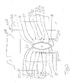
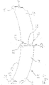
- FIG. 1 and 2 disclosing an embodiment of an apparatus 1 according to the invention for removing a pelt-retaining device 2 from a pelt board 3 on which a mink pelt 4 is retained by means of the pelt-retaining device 2.
- the pelt board 3 has a longitudinal board axis LA, a lower end 6 and an opposite upper end 5, a first major side 7 and an opposite second major side 8, a first lateral side 9 and an opposite second lateral side 10 and a middle plane extending through the board axis LA and through the lateral sides 9,10.
- the lower end 6 of the pelt board 3 is fixed in a pelt board-holding device, not shown, to arrange the pelt board in an upright position.
- the pelt retaining device 2 comprises a first elongated element 12 and an identical second elongated element 12, each having a length, a width and a thickness, an inner surface 13 and an opposite outer surface 14 and a first longitudinally outer end portion 15 and an opposite second longitudinally outer end portion 16, see Fig.7 disclosing the elongated element 12 in a bent state.
- the elongated elements 12 are elastically bendable and arranged opposite each other on respective major sides 7,8 of the pelt board 3 and bent to bring the respective inner surfaces 13 in retaining engagement with the outer surface of the pelt and retain the pelt on the pelt board 2, opposite outer end portions 15,16 of each of the elongated elements extending beyond the first and the second lateral side 9,10 of the pelt board 2.
- Adjacent outer end portions 15,16 of the elongated elements 12 are mutually connected by means of a ratchet-pawl arrangement comprising a ratchet bar 17 with a plurality of teeth 11 being provided at and being integral with one of the outer end portions 15 and a pawl means 18 being provided at the other one of the adjacent outer end portions 16. It should be noted that the elongated elements are straight in their original state before being bent except from the ratchet bar 17 and the pawl means 18.
- Each elongated element 12 is on the outer surface 14 thereof provided with a handle part 20 arranged essentially centrally of the elongated element and protruding from the outer surface 14.
- the handle part 20 comprises a centrally arranged and transversely extending rib 21 with a lateral wedge-shaped through-going notch.
- a T-shaped portion 23 of the handle part 20 extends outwardly beyond the outer surface 14 at the upper edge of the rib 21 and ends in the crossbar 24 of the T.
- the apparatus 1 comprises an essentially C-shaped housing 25 comprising a first housing part 26, an opposite second housing part 27 spaced from the first housing part and a third housing part 28 connected to the first and second housing parts at first ends thereof.
- the opposite second ends of the first and second housing parts 26.27 define an opening to allow passage of the pelt board 2 therethrough and into the space 29 between the first and the second housing parts.
- the first and second housing parts are spaced to accommodate the pelt board fastened in the pelt board-holding device with the pelt-retaining device 2 retaining the pelt 4 on the pelt board and the elongated elements 12 of the retaining device facing respective inwardly facing sides 30,31 of the first and second housing part 26,27, respectively, in a first position of the housing.
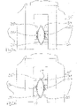
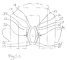
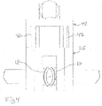
- the first position of the housing is shown in Figs. 1-3 , Figs. 3a-3e and Fig. 4 .
- a first gripping and releasing device 32 for gripping and releasing the first elongated element 12 of the retaining device 2 is arranged in the first housing part 26 and a second gripping and releasing device 33 for gripping and releasing the second elongated element 12 of the retaining device 2 is arranged in the second housing part 27.
- Each of the first and second gripping and releasing devices 32,33 comprise a first and a second mutually spaced pressure rods 34.35 and a gripping member 36.
- the first and a second pressure rod 34,35 are mutually spaced corresponding essentially to the spacing between the outer end portions 15,16 of the elongated elements 12, and each pressure rod is relative to the inwardly facing side 30,31 of the respective housing part 26,27 movable between a retracted position and an extending position.
- the pressure rod engages, in the first position of the housing, an outer end portion 15,16 of an elongated element 12 of a pelt-retaining device 2 arranged on a pelt board 3 fastened in the pelt board-holding device.
- the gripping member 36 is relative to the inwardly facing side of the respective housing part 26,27 moveable between a retracted position and an extending position and comprises a first and a second arm 38,39 comprising at an outer end thereof cooperating gripping and engagement means 37a,37b being movable away from and towards each other and configured to engage and grip, in the first position of the housing, the handle part 20 protruding from the outer surface 14 of each of the longitudinal elements 12, see Fig. 8 .
- the apparatus can comprise additional pressure rods illustrated by the arrows 40,41 and being moveable between a retracted position an extended position. In the extended position, a pressure is applied to the outer free end of the ratchet bar 17 in a direction towards the pelt board, such as towards the longitudinal board axis LA.
- the housing 25 is arranged on a housing support 42 and moveable in a transverse direction along tracks 43 of the housing support 42 between the first housing position, shown in Figs. 1-3 , Figs. 3a-3e and Fig. 4 , where the retaining device 2 on the pelt board is arranged between the inwardly facing sides of the first and second housing parts 26,27 and a second position where the housing 25 is moved transversely away from the pelt board 3 and the pelt board is not accommodated in the spacing 29 between the first and second housing parts.
- the housing support 42, and thereby the housing 25, is additionally moveable along an upright column 44 having a column axis being essentially parallel to the longitudinal pelt board axis LA, when a pelt board 3 is fastened in the pelt board-holding device.
- the housing 25 supported by the housing support can be moved to any vertical position and especially to the first position where the gripping and releasing devices are in the position for gripping and releasing the elongated elements of the retaining device and remove the latter from the pelt.
- the housing support 42 is movable between a position where the housing 25 is in its second position and a position where the housing is in an elevated third position.
- the housing support and thereby the housing 25 is laterally movable to a position where the housing is in a fourth position above an upper opening 45 of a retaining device store 46 configured for receiving the elongated elements 12 of the retaining device 2.
- the retaining device store 46 is preferably movable relative to the housing supported by the housing support in order to arrange each opening of a retaining device store 46 having a number of openings in the correct position for receiving the elongated elements 12 of the retaining device when they are released.
- the retaining device store 46 has a number of upwardly open storing rooms divided into two storing compartments 47, 48 by means of a dividing wall 49.
- the storing compartments are configured and shaped to receive and stack the pairs of elongated elements 12 of the retaining device 2 corresponding to the pairs of elongated elements forming the retaining device being removed from the retaining engagement with the pelt on the pelt board.
- the compartments 47, 48 can be configured and shaped to receive and store the elongated elements 12 in the shape of the elongated elements before being elastically bent to bring the respective inner surfaces thereof in retaining engagement with the outer surface of the pelt and retain the pelt on the pelt board, see especially Fig 6a .
- the pelt-retaining device 2 comprising two identical elongated elements can be removed by a method of the invention according to the following steps carried out by means of the above described embodiment of the apparatus of the invention:
- step c1 When a pressure is applied during step c1 to each of the outer end portions of the elongated members being provided with a pawl means, the pawl means flexes outwardly away from and out of a possible engagement between a tooth of the ratchet bar. Thereby, the risk of not obtaining a disengagement of the ratchet bar from the pawl means is eliminated. If not, it is possible to apply a pressure to the outer free end of the ratchet bar in a direction towards the pelt board, such as the longitudinal board axis by means of the pressure rods illustrated by means of the arrows 40 and 41 in Fig. 3d in order to disengage the ratchet bar from the pawl means.
- the gripping members 36 are retracted to their retracted position, thereby removing the elongated element of the retaining device 2 from the pelt board as mentioned above.
- the pelt can then be removed from the pelt board.
- the elongated elements 12 of the pelt-retaining device 2 gripped by the gripping members 36 can be delivered to the retaining device store 46 by moving the housing 25 supported by the housing support to its second position and thereafter moving the housing on the housing support 42 to its elevated third position. The housing 25 on the housing support 42 is then moved to its fourth position above the upper opening 45 of the retaining device store 46 as shown in Fig.5 and 6 .
- the gripping members 36 of the gripping and releasing devices 32, 33 can be extended to their extended positions to bring the elongated elements from their bent shape and state shown in Figs. 5 and 6 and into their straight shape and state shown in Fig. 6a .
- the housing 25 can then be moved downwardly to insert the elongated elements 12 in the respective storing compartments 47,48 of the retaining device store 46.
- the gripping members 36 of the gripping and releasing devices 32, 33 can now be retracted to their retracted positions leaving the elongated elements in the respective compartments 47,48.
- the housing is moved back to its first position for removing the next pelt-retaining device from a pelt on a pelt board.
Landscapes
- Engineering & Computer Science (AREA)
- Mechanical Engineering (AREA)
- Chemical & Material Sciences (AREA)
- Organic Chemistry (AREA)
- Manufacturing & Machinery (AREA)
- Supply And Installment Of Electrical Components (AREA)
- Packaging Frangible Articles (AREA)
Claims (15)
- Verfahren zum Entfernen einer Pelzhaltevorrichtung (2) von einem Pelzbrett (3), auf welchem ein Pelz (4), insbesondere ein Nerzpelz, während eines Trocknungsvorgangs von der Haltevorrichtung (2) gehalten wurde, wobei das Pelzbrett (3) eine Brett-Längsachse (LA), eine Längsmittelebene, ein unteres Ende (6), ein gegenüberliegendes oberes Ende (5) und eine erste Hauptseite (7) und eine gegenüberliegende zweite Hauptseite (8) und eine erste laterale Seite (9) und eine gegenüberliegende zweite laterale Seite (10) aufweist, wobei die Pelzhaltevorrichtung (2) ein erstes längliches Element (12) und ein zweites längliches Element (12) umfasst, die jeweils eine Länge, eine Breite und eine Dicke, eine Innenfläche (13) und eine gegenüberliegende Außenfläche (14) und einen ersten in Längsrichtung äußeren Endabschnitt (15) und einen gegenüberliegenden zweiten in Längsrichtung äußeren Endabschnitt (16) aufweisen,
dadurch gekennzeichnet, dass dielänglichen Elemente (12) elastisch biegsam sind und einander gegenüberliegend auf einer jeweiligen Hauptseite (7, 8) des Pelzbrettes (3) angeordnet und so gebogen werden, dass die jeweilige Innenfläche (13) mit der Außenfläche des Pelzes in Halteeingriff gebracht und der Pelz auf dem Pelzbrett gehalten wird, wobei sich gegenüberliegende äußere Endabschnitte (15, 16) jedes der länglichen Elemente (12) über die erste und die zweite laterale Seite (9, 10) des Pelzbrettes (3) hinaus erstrecken, undaneinandergrenzenden äußeren Endabschnitte (15, 16) der länglichen Elemente (12) mittels einer Sperrklinkenanordnung, die eine Sperrstange (17) mit einer Vielzahl von Zähnen (11), welche an einem der äußeren Endabschnitte (15) bereitgestellt und mit diesem einstückig ist, und ein Klinkenmittel (18) umfasst, welches am anderen der aneinandergrenzenden äußeren Endabschnitte (16) bereitgestellt und mit diesem einstückig ist, miteinander verbunden werden, wobei das Verfahren die folgenden Schritte umfasst:a. Anordnen des unteren Endes des Pelzbrettes (3) mit dem Pelz (4), der mittels der Haltevorrichtung (2) auf diesem gehalten wird, in einer Pelzbrett-Halterungsvorrichtung,b. Ineingriffbringen eines Greifgliedes (36) mit der Außenfläche (14) jedes der länglichen Elemente (12), die einander gegenüberliegend auf einer jeweiligen Hauptseite (7, 8) des Brettes (3) angeordnet sind,c. Anlegen eines Drucks auf die Außenfläche jedes der äußeren Endabschnitte (15) der länglichen Glieder (12), die mit einer Sperrstange (17) versehen sind, um die Sperrstange (17) und das Klinkenmittel (18) außer Eingriff zu bringen,e. Bewegen der Greifglieder (36), die sich mit den jeweiligen länglichen Gliedern (12) in Eingriff befinden, vom Pelz (4) auf dem Pelzbrett (3) weg, wodurch die länglichen Glieder (12) vom Pelz (4) entfernt werden, nachdem der Druck auf jedem der äußeren Endabschnitte (15) der länglichen Elemente (12) gelöst wurde. - Verfahren nach Anspruch 1, wobei das Pelzbrett (3) in Schritt a in einer aufrechten Stellung angeordnet wird.
- Verfahren nach einem der vorstehenden Ansprüche, wobei das Verfahren die folgenden Schritte in Verbindung mit oder nach Schritt c umfasst:Schritt c1: Anlegen eines Drucks auf jeden der äußeren Endabschnitte (16) der länglichen Glieder (12), der mit einem Klinkenmittel (18) versehen ist, undSchritt c2: Lösen des Drucks auf jedem der äußeren Endabschnitte (16) der länglichen Glieder (12), der mit einem Klinkenmittel (18) versehen ist, undSchritt c3: Lösen des Drucks auf jedem der äußeren Endabschnitte (15) der länglichen Glieder (12), der mit einer Sperrstange (17) versehen ist.
- Verfahren nach Anspruch 1 und/oder Anspruch 3, wobei das Verfahren das Anlegen eines Drucks in einer Richtung zur Brett-Längsachse (LA) auf das äußere freie Ende der Sperrstange (17) umfasst, um die Sperrstange (17) und das Klinkenmittel (18) außer Eingriff zu bringen.
- Verfahren nach einem der vorstehenden Ansprüche, wobei das Verfahren im Anschluss an (nachfolgend auf) Schritt e den folgenden Schritt umfasst:
Schritt f: Entfernen des Pelzes (4) vom Pelzbrett (3). - Verfahren nach einem der vorstehenden Ansprüche, wobei das Verfahren im Anschluss an Schritt e den folgenden Schritt umfasst:
Schritt g: Zuführen der länglichen Elemente (12) der Haltevorrichtung (2) einem Haltevorrichtungsmagazin (46). - Verfahren nach Anspruch 6, wobei die länglichen Elemente (12) dem Magazin (46) paarweise, dem Paar länglicher Elemente (12) entsprechend, welches die aus dem Halteeingriff mit dem Pelz (4) auf dem Pelzbrett (3) entfernte Haltevorrichtung (2) bildet, zugeführt und in diesem gelagert werden.
- Verfahren nach Anspruch 7, wobei die Paare länglicher Elemente (12) im Magazin (46) in Stellungen gelagert werden, bei denen eine Sperrstange (17) eines der länglichen Elemente (12) dem Klinkenmittel (18) des anderen des Paars länglicher Elemente (12) gegenüberliegend platziert ist.
- Verfahren nach Anspruch 7 und/oder 8, wobei die länglichen Elemente (12) im Magazin (46) in einer Form gelagert werden, die der Form des länglichen Elements (12) entspricht, bevor dieses elastisch gebogen wird, um die jeweilige Innenfläche desselben mit der Außenfläche des Pelzes in Halteeingriff zu bringen und den Pelz auf dem Pelzbrett zu halten.
- Einrichtung (1) zum Entfernen einer Pelzhaltevorrichtung (2) von einem Pelzbrett (3), auf welchem ein Pelz (4), insbesondere ein Nerzpelz, während eines Trocknungsvorgangs von der Haltevorrichtung (2) gehalten wurde, wobei das Pelzbrett (3) eine Brett-Längsachse (LA), eine Längsmittelebene, ein unteres Ende (6), ein gegenüberliegendes oberes Ende (5) und eine erste Hauptseite (7) und eine gegenüberliegende zweite Hauptseite (8) und eine erste laterale Seite (9) und eine gegenüberliegende zweite laterale Seite (10) aufweist,wobei die Pelzhaltevorrichtung (2) ein erstes längliches Element (12) und ein zweites längliches Element (12) umfasst, die jeweils eine Länge, eine Breite und eine Dicke, eine Innenfläche (13) und eine gegenüberliegende Außenfläche (14) und einen ersten in Längsrichtung äußeren Endabschnitt (15) und einen gegenüberliegenden zweiten in Längsrichtung äußeren Endabschnitt (16) aufweisen,dadurch gekennzeichnet, dass dielänglichen Elemente (12) elastisch biegsam sind und einander gegenüberliegend auf einer jeweiligen Hauptseite (7, 8) des Pelzbrettes (3) angeordnet und so gebogen werden, dass die jeweilige Innenfläche (13) mit der Außenfläche des Pelzes (4) in Halteeingriff gebracht und der Pelz auf dem Pelzbrett (3) gehalten wird, wobei sich gegenüberliegende äußere Endabschnitte jedes der länglichen Elemente (12) über die erste und die zweite laterale Seite (9, 10) des Pelzbrettes (3) hinaus erstrecken, undaneinandergrenzenden äußeren Endabschnitte (15, 16) der länglichen Elemente mittels einer Sperrklinkenanordnung, die eine Sperrstange (17) mit einer Vielzahl von Zähnen (11), welche an einem der äußeren Endabschnitte bereitgestellt und mit diesem einstückig ist, und ein Klinkenmittel (18) umfasst, welches am anderen der aneinandergrenzenden äußeren Endabschnitte (16) bereitgestellt ist, miteinander verbunden werden, wobei die Einrichtung umfasst:- eine Pelzbrett-Halterungsvorrichtung, die dafür ausgelegt ist, das untere Ende (6) des Pelzbrettes (3) in einer vorzugsweise aufrechten Stellung vorzugsweise lösbar zu befestigen,- ein Gehäuse (25), das einen ersten Gehäuseteil (26) und einen gegenüberliegenden zweiten Gehäuseteil (27) umfasst, die zueinander beabstandet sind, um das in der Pelzbrett-Halterungsvorrichtung befestigte Pelzbrett (3) mit der den Pelz (4) auf dem Pelzbrett (3) haltenden Haltevorrichtung (2) und den länglichen Elementen (12) der Haltevorrichtung (2) in einer ersten Stellung des Gehäuses (25) einer jeweiligen nach innen gewandten Seite (30, 31) des ersten bzw. des zweiten Gehäuseteils (26, 27) zugewandt unterzubringen.- eine erste Greif- und Lösevorrichtung (32) zum Greifen und Lösen des ersten länglichen Elements (12) der Haltevorrichtung (2) und im ersten Gehäuseteil (26) angeordnet werden, und eine zweite Greif- und Lösevorrichtung (33) zum Greifen und Lösen des zweiten länglichen Elements (12) der Haltevorrichtung (2) und im zweiten Gehäuseteil (27) angeordnet werden,- wobei die erste und die zweite Greif- und Lösevorrichtung (32, 33) jeweils umfassen:- einen ersten und einen zweiten Druckstab (34, 35), die im Wesentlichen dem Abstand zwischen den äußeren Endabschnitten (15, 16) der länglichen Elemente (12) entsprechend zueinander beabstandet sind und jeweils relativ zu der nach innen gewandten Seite (30, 31) des jeweiligen Gehäuseteils (26, 27) zwischen einer eingezogenen Stellung und einer sich erstreckenden Stellung bewegt werden können, welche in der ersten Stellung des Gehäuses (25) einen äußeren Endabschnitt eines länglichen Elements (12) einer Pelzhaltevorrichtung (2), die auf einem in der Pelzbrett-Halterungsvorrichtung befestigten Pelzbrett (3) angeordnet ist, in Eingriff nimmt, und- ein Greifglied (36), das relativ zu der nach innen gewandten Seite (30, 31) des jeweiligen Gehäuseteils (26, 27) zwischen einer eingezogenen Stellung und einer sich erstreckenden Stellung bewegt werden kann und an einem äußeren Ende desselben zusammenwirkende Greif- und Eingriffsmittel (37a, 37b) umfasst, die auseinander und zueinander bewegt werden können und dazu ausgelegt sind, in der ersten Stellung des Gehäuses (25), einen von der Außenfläche (14) jedes der länglichen Elemente (12) vorstehenden Griffteil (20) in Eingriff zu nehmen und zu greifen.
- Einrichtung nach Anspruch 10, wobei der Griffteil (20), in der Längsrichtung derselben gesehen, im Wesentlichen mittig von den jeweiligen länglichen Elementen (12) angeordnet ist, und das Greifglied (36) im Wesentlichen auf halber Strecke zwischen dem ersten und dem zweiten Druckstab (34, 35) angeordnet ist.
- Einrichtung nach Anspruch 10 und/oder 11, wobei das Gehäuse (25) an einem Gehäuseträger (42) angeordnet ist, der entlang von Schienen (43) in einer Querrichtung zwischen der ersten Gehäusestellung, bei der die Haltevorrichtung (2) auf dem Pelzbrett zwischen den nach innen gewandten Seiten (30, 31) der Gehäuseteile (26, 27) angeordnet ist, und einer zweiten Stellung bewegt werden kann, bei der das Gehäuse (25) quer vom Pelzbrett weg bewegt wird und das Pelzbrett nicht in dem Raum zwischen den Gehäuseteilen untergebracht ist.
- Einrichtung nach Anspruch 12, wobei der Gehäuseträger (42) entlang einer Säule (44) mit einer im Wesentlichen parallel zur Brett-Längsachse (LA) eines in der Pelzbrett-Halterungsvorrichtung befestigten Pelzbrettes (3) verlaufenden Säulenachse beweglich angeordnet ist, wobei der Gehäuseträger (42) zwischen einer Stellung, bei der sich das Gehäuse (25) in seiner zweiten Stellung befindet, und einer Stellung, bei der sich das Gehäuse in einer angehobenen dritten Stellung befindet, bewegt werden kann, und wobei in der Stellung des Gehäuseträgers, bei der sich das Gehäuse (25) in seiner dritten Stellung befindet, der Gehäuseträger (42) und damit das Gehäuse (25) seitwärts zu einer Stellung bewegt werden können, bei der sich das Gehäuse (25) in einer vierten Stellung über einer oberen Öffnung eines Haltevorrichtungslagers (46) befindet, das dafür ausgelegt ist, das längliche Element (12) der Haltevorrichtung (2) aufzunehmen.
- Einrichtung nach Anspruch 13, wobei es sich bei dem Haltevorrichtungslager (46) um ein Haltevorrichtungsmagazin mit mindestens einem nach oben offenen Lagerraum handelt, der mittels einer Trennwand (49) in zwei Lagerabteile (47, 48) getrennt ist, wobei die Lagerabteile (47, 48) dazu ausgelegt und geformt sind, die Paare länglicher Elemente (12) der Haltevorrichtung (2) den Paaren länglicher Elemente (12) entsprechend, welche die aus dem Halteeingriff mit dem Pelz (4) auf dem Pelzbrett (3) entfernte Haltevorrichtung (2) bilden, aufzunehmen und zu stapeln.
- Einrichtung nach Anspruch 14, wobei die Abteile (47, 48) dazu ausgelegt und geformt sind, die länglichen Elemente (12) in der Form der länglichen Elemente, bevor diese elastisch gebogen werden, um die jeweiligen Innenflächen derselben mit der Außenfläche des Pelzes (4) in Halteeingriff zu bringen und den Pelz auf dem Pelzbrett (3) zu halten, aufzunehmen und zu lagern.
Priority Applications (3)
| Application Number | Priority Date | Filing Date | Title |
|---|---|---|---|
| PL19155598.6T PL3693477T3 (pl) | 2019-02-05 | 2019-02-05 | Sposób i urządzenie do usuwania urządzenia do utrzymywania skóry surowej z deski do skór surowych |
| EP19155598.6A EP3693477B1 (de) | 2019-02-05 | 2019-02-05 | Verfahren und vorrichtung zum entfernen einer pelzrückhaltevorrichtung von einem pelzbrett |
| DK19155598.6T DK3693477T3 (da) | 2019-02-05 | 2019-02-05 | En fremgangsmåde og et apparat til fjernelse af en skindfastholdelsesindretning fra en tane |
Applications Claiming Priority (1)
| Application Number | Priority Date | Filing Date | Title |
|---|---|---|---|
| EP19155598.6A EP3693477B1 (de) | 2019-02-05 | 2019-02-05 | Verfahren und vorrichtung zum entfernen einer pelzrückhaltevorrichtung von einem pelzbrett |
Publications (2)
| Publication Number | Publication Date |
|---|---|
| EP3693477A1 EP3693477A1 (de) | 2020-08-12 |
| EP3693477B1 true EP3693477B1 (de) | 2022-09-14 |
Family
ID=65324281
Family Applications (1)
| Application Number | Title | Priority Date | Filing Date |
|---|---|---|---|
| EP19155598.6A Active EP3693477B1 (de) | 2019-02-05 | 2019-02-05 | Verfahren und vorrichtung zum entfernen einer pelzrückhaltevorrichtung von einem pelzbrett |
Country Status (3)
| Country | Link |
|---|---|
| EP (1) | EP3693477B1 (de) |
| DK (1) | DK3693477T3 (de) |
| PL (1) | PL3693477T3 (de) |
Families Citing this family (1)
| Publication number | Priority date | Publication date | Assignee | Title |
|---|---|---|---|---|
| CN113755651B (zh) * | 2021-09-01 | 2022-09-09 | 临沂市双旭汽车用品有限公司 | 皮革切断过程中对毛边处理的铲皮机及其处理工艺 |
Family Cites Families (5)
| Publication number | Priority date | Publication date | Assignee | Title |
|---|---|---|---|---|
| DK1285094T3 (da) | 2000-02-25 | 2007-04-23 | Majgaard Invest As | Fremgangsmåde og organ til törring og fastgörelse af skind trukket på en tane |
| DK176100B1 (da) | 2004-02-24 | 2006-06-06 | 4M Globe Man Ltd | Fremgangsmåde og apparat til fiksering af et pelsdyrskind på en tane |
| DK178571B1 (da) | 2014-12-19 | 2016-07-04 | Pamutec Patents Aps | Tanelås med fikseringsmidler |
| EP3181706A1 (de) * | 2015-12-15 | 2017-06-21 | Minkpapir A/S | Vorrichtungen und verfahren zum strecken eines pelzes auf einem pelzbrett |
| EP3415645B1 (de) * | 2017-06-16 | 2024-05-29 | Hedensted Gruppen A/S | Verfahren zum strecken eines pelzes auf einem pelzbrett |
-
2019
- 2019-02-05 PL PL19155598.6T patent/PL3693477T3/pl unknown
- 2019-02-05 DK DK19155598.6T patent/DK3693477T3/da active
- 2019-02-05 EP EP19155598.6A patent/EP3693477B1/de active Active
Also Published As
| Publication number | Publication date |
|---|---|
| DK3693477T3 (da) | 2022-12-05 |
| EP3693477A1 (de) | 2020-08-12 |
| PL3693477T3 (pl) | 2022-12-05 |
Similar Documents
| Publication | Publication Date | Title |
|---|---|---|
| KR970064479A (ko) | 증모방법 및 거기에 사용하는 증모용구 | |
| US6434807B1 (en) | Apparatus for removing and replacing coil springs and fasteners | |
| US3547258A (en) | Adjustable pallet and method for shipping and storing vehicle tires | |
| EP3693477A1 (de) | Verfahren und vorrichtung zum entfernen einer pelzrückhaltevorrichtung von einem pelzbrett | |
| EP2066481A1 (de) | Verfahren und bewehrungsmittel zur herstellung bewehrter poren- oder schaumbetonkörper und bewehrungshalterahmen zur verwendung für ein derartiges verfahren | |
| WO2012159745A2 (de) | Interdentalreiniger-set und verkaufseinheit für dieses | |
| DE69604892T2 (de) | Greifvorrichtung für Umreifungsmaschine | |
| BE1001479A3 (nl) | Werkwijze voor het toevoeren van vezels aan borstelvervaardigingsmachines en inrichting die deze werkwijze toepast. | |
| EP1034723B1 (de) | Verfahren und Einrichtung zur Bildung von Faserblöcken zur Herstellung von Bürsten aus Fasersträngen | |
| US1057799A (en) | Lath-holder. | |
| US2867806A (en) | Fastener strip | |
| EP3479698B1 (de) | Schinkenbeladungs- und -entfernungsvorrichtung | |
| US3333592A (en) | Looseleaf binder | |
| WO2024059002A1 (en) | Loom and double hook tool for forming brunnian links | |
| DK178142B1 (en) | Device and method for placing or removing a pelt board | |
| JP4616146B2 (ja) | スリットコイルの結束方法 | |
| DE69813900T2 (de) | Verfahren und vorrichtung zum zwischenspeichern von druckerzeugnissen | |
| US2738213A (en) | Tobacco curing stick | |
| US2944751A (en) | Packing device for pile fabrics | |
| EP1550781A3 (de) | Endstück für ein Distanzrohr zum Führen von Spannstäben | |
| DE3801242A1 (de) | Verfahren zum auszeichnen einer bananenhand unter verwendung eines bananenaufhaengers | |
| KR200220256Y1 (ko) | 퍼머용 모발성형기구 | |
| JP2526815Y2 (ja) | 釣針の根掛り外し具 | |
| EP3501265B1 (de) | Streifen mit mehreren pflanzenstützeinheiten zur unterstützung eines pflanzenstammes einer pflanze | |
| US1906721A (en) | Column clamp |
Legal Events
| Date | Code | Title | Description |
|---|---|---|---|
| PUAI | Public reference made under article 153(3) epc to a published international application that has entered the european phase |
Free format text: ORIGINAL CODE: 0009012 |
|
| STAA | Information on the status of an ep patent application or granted ep patent |
Free format text: STATUS: THE APPLICATION HAS BEEN PUBLISHED |
|
| AK | Designated contracting states |
Kind code of ref document: A1 Designated state(s): AL AT BE BG CH CY CZ DE DK EE ES FI FR GB GR HR HU IE IS IT LI LT LU LV MC MK MT NL NO PL PT RO RS SE SI SK SM TR |
|
| AX | Request for extension of the european patent |
Extension state: BA ME |
|
| STAA | Information on the status of an ep patent application or granted ep patent |
Free format text: STATUS: REQUEST FOR EXAMINATION WAS MADE |
|
| 17P | Request for examination filed |
Effective date: 20210211 |
|
| RBV | Designated contracting states (corrected) |
Designated state(s): AL AT BE BG CH CY CZ DE DK EE ES FI FR GB GR HR HU IE IS IT LI LT LU LV MC MK MT NL NO PL PT RO RS SE SI SK SM TR |
|
| GRAP | Despatch of communication of intention to grant a patent |
Free format text: ORIGINAL CODE: EPIDOSNIGR1 |
|
| STAA | Information on the status of an ep patent application or granted ep patent |
Free format text: STATUS: GRANT OF PATENT IS INTENDED |
|
| INTG | Intention to grant announced |
Effective date: 20220411 |
|
| GRAS | Grant fee paid |
Free format text: ORIGINAL CODE: EPIDOSNIGR3 |
|
| GRAA | (expected) grant |
Free format text: ORIGINAL CODE: 0009210 |
|
| STAA | Information on the status of an ep patent application or granted ep patent |
Free format text: STATUS: THE PATENT HAS BEEN GRANTED |
|
| AK | Designated contracting states |
Kind code of ref document: B1 Designated state(s): AL AT BE BG CH CY CZ DE DK EE ES FI FR GB GR HR HU IE IS IT LI LT LU LV MC MK MT NL NO PL PT RO RS SE SI SK SM TR |
|
| REG | Reference to a national code |
Ref country code: GB Ref legal event code: FG4D |
|
| REG | Reference to a national code |
Ref country code: CH Ref legal event code: EP |
|
| REG | Reference to a national code |
Ref country code: DE Ref legal event code: R096 Ref document number: 602019019467 Country of ref document: DE |
|
| REG | Reference to a national code |
Ref country code: IE Ref legal event code: FG4D |
|
| REG | Reference to a national code |
Ref country code: AT Ref legal event code: REF Ref document number: 1518723 Country of ref document: AT Kind code of ref document: T Effective date: 20221015 |
|
| REG | Reference to a national code |
Ref country code: DK Ref legal event code: T3 Effective date: 20221130 |
|
| REG | Reference to a national code |
Ref country code: LT Ref legal event code: MG9D |
|
| REG | Reference to a national code |
Ref country code: NL Ref legal event code: MP Effective date: 20220914 |
|
| PG25 | Lapsed in a contracting state [announced via postgrant information from national office to epo] |
Ref country code: SE Free format text: LAPSE BECAUSE OF FAILURE TO SUBMIT A TRANSLATION OF THE DESCRIPTION OR TO PAY THE FEE WITHIN THE PRESCRIBED TIME-LIMIT Effective date: 20220914 Ref country code: RS Free format text: LAPSE BECAUSE OF FAILURE TO SUBMIT A TRANSLATION OF THE DESCRIPTION OR TO PAY THE FEE WITHIN THE PRESCRIBED TIME-LIMIT Effective date: 20220914 Ref country code: NO Free format text: LAPSE BECAUSE OF FAILURE TO SUBMIT A TRANSLATION OF THE DESCRIPTION OR TO PAY THE FEE WITHIN THE PRESCRIBED TIME-LIMIT Effective date: 20221214 Ref country code: LV Free format text: LAPSE BECAUSE OF FAILURE TO SUBMIT A TRANSLATION OF THE DESCRIPTION OR TO PAY THE FEE WITHIN THE PRESCRIBED TIME-LIMIT Effective date: 20220914 Ref country code: LT Free format text: LAPSE BECAUSE OF FAILURE TO SUBMIT A TRANSLATION OF THE DESCRIPTION OR TO PAY THE FEE WITHIN THE PRESCRIBED TIME-LIMIT Effective date: 20220914 Ref country code: FI Free format text: LAPSE BECAUSE OF FAILURE TO SUBMIT A TRANSLATION OF THE DESCRIPTION OR TO PAY THE FEE WITHIN THE PRESCRIBED TIME-LIMIT Effective date: 20220914 |
|
| REG | Reference to a national code |
Ref country code: AT Ref legal event code: MK05 Ref document number: 1518723 Country of ref document: AT Kind code of ref document: T Effective date: 20220914 |
|
| PG25 | Lapsed in a contracting state [announced via postgrant information from national office to epo] |
Ref country code: HR Free format text: LAPSE BECAUSE OF FAILURE TO SUBMIT A TRANSLATION OF THE DESCRIPTION OR TO PAY THE FEE WITHIN THE PRESCRIBED TIME-LIMIT Effective date: 20220914 Ref country code: GR Free format text: LAPSE BECAUSE OF FAILURE TO SUBMIT A TRANSLATION OF THE DESCRIPTION OR TO PAY THE FEE WITHIN THE PRESCRIBED TIME-LIMIT Effective date: 20221215 |
|
| PG25 | Lapsed in a contracting state [announced via postgrant information from national office to epo] |
Ref country code: SM Free format text: LAPSE BECAUSE OF FAILURE TO SUBMIT A TRANSLATION OF THE DESCRIPTION OR TO PAY THE FEE WITHIN THE PRESCRIBED TIME-LIMIT Effective date: 20220914 Ref country code: RO Free format text: LAPSE BECAUSE OF FAILURE TO SUBMIT A TRANSLATION OF THE DESCRIPTION OR TO PAY THE FEE WITHIN THE PRESCRIBED TIME-LIMIT Effective date: 20220914 Ref country code: PT Free format text: LAPSE BECAUSE OF FAILURE TO SUBMIT A TRANSLATION OF THE DESCRIPTION OR TO PAY THE FEE WITHIN THE PRESCRIBED TIME-LIMIT Effective date: 20230116 Ref country code: ES Free format text: LAPSE BECAUSE OF FAILURE TO SUBMIT A TRANSLATION OF THE DESCRIPTION OR TO PAY THE FEE WITHIN THE PRESCRIBED TIME-LIMIT Effective date: 20220914 Ref country code: CZ Free format text: LAPSE BECAUSE OF FAILURE TO SUBMIT A TRANSLATION OF THE DESCRIPTION OR TO PAY THE FEE WITHIN THE PRESCRIBED TIME-LIMIT Effective date: 20220914 Ref country code: AT Free format text: LAPSE BECAUSE OF FAILURE TO SUBMIT A TRANSLATION OF THE DESCRIPTION OR TO PAY THE FEE WITHIN THE PRESCRIBED TIME-LIMIT Effective date: 20220914 |
|
| PG25 | Lapsed in a contracting state [announced via postgrant information from national office to epo] |
Ref country code: SK Free format text: LAPSE BECAUSE OF FAILURE TO SUBMIT A TRANSLATION OF THE DESCRIPTION OR TO PAY THE FEE WITHIN THE PRESCRIBED TIME-LIMIT Effective date: 20220914 Ref country code: IS Free format text: LAPSE BECAUSE OF FAILURE TO SUBMIT A TRANSLATION OF THE DESCRIPTION OR TO PAY THE FEE WITHIN THE PRESCRIBED TIME-LIMIT Effective date: 20230114 Ref country code: EE Free format text: LAPSE BECAUSE OF FAILURE TO SUBMIT A TRANSLATION OF THE DESCRIPTION OR TO PAY THE FEE WITHIN THE PRESCRIBED TIME-LIMIT Effective date: 20220914 |
|
| REG | Reference to a national code |
Ref country code: DE Ref legal event code: R097 Ref document number: 602019019467 Country of ref document: DE |
|
| PG25 | Lapsed in a contracting state [announced via postgrant information from national office to epo] |
Ref country code: NL Free format text: LAPSE BECAUSE OF FAILURE TO SUBMIT A TRANSLATION OF THE DESCRIPTION OR TO PAY THE FEE WITHIN THE PRESCRIBED TIME-LIMIT Effective date: 20220914 Ref country code: AL Free format text: LAPSE BECAUSE OF FAILURE TO SUBMIT A TRANSLATION OF THE DESCRIPTION OR TO PAY THE FEE WITHIN THE PRESCRIBED TIME-LIMIT Effective date: 20220914 |
|
| PLBE | No opposition filed within time limit |
Free format text: ORIGINAL CODE: 0009261 |
|
| STAA | Information on the status of an ep patent application or granted ep patent |
Free format text: STATUS: NO OPPOSITION FILED WITHIN TIME LIMIT |
|
| 26N | No opposition filed |
Effective date: 20230615 |
|
| PG25 | Lapsed in a contracting state [announced via postgrant information from national office to epo] |
Ref country code: SI Free format text: LAPSE BECAUSE OF FAILURE TO SUBMIT A TRANSLATION OF THE DESCRIPTION OR TO PAY THE FEE WITHIN THE PRESCRIBED TIME-LIMIT Effective date: 20220914 |
|
| REG | Reference to a national code |
Ref country code: DE Ref legal event code: R119 Ref document number: 602019019467 Country of ref document: DE |
|
| PG25 | Lapsed in a contracting state [announced via postgrant information from national office to epo] |
Ref country code: MC Free format text: LAPSE BECAUSE OF FAILURE TO SUBMIT A TRANSLATION OF THE DESCRIPTION OR TO PAY THE FEE WITHIN THE PRESCRIBED TIME-LIMIT Effective date: 20220914 |
|
| REG | Reference to a national code |
Ref country code: CH Ref legal event code: PL |
|
| REG | Reference to a national code |
Ref country code: BE Ref legal event code: MM Effective date: 20230228 |
|
| GBPC | Gb: european patent ceased through non-payment of renewal fee |
Effective date: 20230205 |
|
| PG25 | Lapsed in a contracting state [announced via postgrant information from national office to epo] |
Ref country code: LU Free format text: LAPSE BECAUSE OF NON-PAYMENT OF DUE FEES Effective date: 20230205 Ref country code: LI Free format text: LAPSE BECAUSE OF NON-PAYMENT OF DUE FEES Effective date: 20230228 Ref country code: CH Free format text: LAPSE BECAUSE OF NON-PAYMENT OF DUE FEES Effective date: 20230228 |
|
| REG | Reference to a national code |
Ref country code: IE Ref legal event code: MM4A |
|
| PG25 | Lapsed in a contracting state [announced via postgrant information from national office to epo] |
Ref country code: GB Free format text: LAPSE BECAUSE OF NON-PAYMENT OF DUE FEES Effective date: 20230205 |
|
| PG25 | Lapsed in a contracting state [announced via postgrant information from national office to epo] |
Ref country code: IE Free format text: LAPSE BECAUSE OF NON-PAYMENT OF DUE FEES Effective date: 20230205 Ref country code: GB Free format text: LAPSE BECAUSE OF NON-PAYMENT OF DUE FEES Effective date: 20230205 Ref country code: FR Free format text: LAPSE BECAUSE OF NON-PAYMENT OF DUE FEES Effective date: 20230228 Ref country code: DE Free format text: LAPSE BECAUSE OF NON-PAYMENT OF DUE FEES Effective date: 20230901 |
|
| PG25 | Lapsed in a contracting state [announced via postgrant information from national office to epo] |
Ref country code: BE Free format text: LAPSE BECAUSE OF NON-PAYMENT OF DUE FEES Effective date: 20230228 |
|
| PG25 | Lapsed in a contracting state [announced via postgrant information from national office to epo] |
Ref country code: IT Free format text: LAPSE BECAUSE OF FAILURE TO SUBMIT A TRANSLATION OF THE DESCRIPTION OR TO PAY THE FEE WITHIN THE PRESCRIBED TIME-LIMIT Effective date: 20220914 |
|
| PG25 | Lapsed in a contracting state [announced via postgrant information from national office to epo] |
Ref country code: BG Free format text: LAPSE BECAUSE OF FAILURE TO SUBMIT A TRANSLATION OF THE DESCRIPTION OR TO PAY THE FEE WITHIN THE PRESCRIBED TIME-LIMIT Effective date: 20220914 |
|
| PG25 | Lapsed in a contracting state [announced via postgrant information from national office to epo] |
Ref country code: BG Free format text: LAPSE BECAUSE OF FAILURE TO SUBMIT A TRANSLATION OF THE DESCRIPTION OR TO PAY THE FEE WITHIN THE PRESCRIBED TIME-LIMIT Effective date: 20220914 |
|
| PG25 | Lapsed in a contracting state [announced via postgrant information from national office to epo] |
Ref country code: CY Free format text: LAPSE BECAUSE OF FAILURE TO SUBMIT A TRANSLATION OF THE DESCRIPTION OR TO PAY THE FEE WITHIN THE PRESCRIBED TIME-LIMIT; INVALID AB INITIO Effective date: 20190205 |
|
| PG25 | Lapsed in a contracting state [announced via postgrant information from national office to epo] |
Ref country code: HU Free format text: LAPSE BECAUSE OF FAILURE TO SUBMIT A TRANSLATION OF THE DESCRIPTION OR TO PAY THE FEE WITHIN THE PRESCRIBED TIME-LIMIT; INVALID AB INITIO Effective date: 20190205 |
|
| PG25 | Lapsed in a contracting state [announced via postgrant information from national office to epo] |
Ref country code: TR Free format text: LAPSE BECAUSE OF FAILURE TO SUBMIT A TRANSLATION OF THE DESCRIPTION OR TO PAY THE FEE WITHIN THE PRESCRIBED TIME-LIMIT Effective date: 20220914 |
|
| PGFP | Annual fee paid to national office [announced via postgrant information from national office to epo] |
Ref country code: DK Payment date: 20260204 Year of fee payment: 8 |
|
| PGFP | Annual fee paid to national office [announced via postgrant information from national office to epo] |
Ref country code: PL Payment date: 20260121 Year of fee payment: 8 |