EP3693324A1 - Elektrozug mit synchronriemen - Google Patents
Elektrozug mit synchronriemen Download PDFInfo
- Publication number
- EP3693324A1 EP3693324A1 EP20155861.6A EP20155861A EP3693324A1 EP 3693324 A1 EP3693324 A1 EP 3693324A1 EP 20155861 A EP20155861 A EP 20155861A EP 3693324 A1 EP3693324 A1 EP 3693324A1
- Authority
- EP
- European Patent Office
- Prior art keywords
- pulleys
- winch
- drive
- traction
- pulley
- Prior art date
- Legal status (The legal status is an assumption and is not a legal conclusion. Google has not performed a legal analysis and makes no representation as to the accuracy of the status listed.)
- Withdrawn
Links
- 230000001360 synchronised effect Effects 0.000 title claims description 15
- 239000004020 conductor Substances 0.000 claims abstract description 31
- 230000005540 biological transmission Effects 0.000 claims description 71
- 238000003860 storage Methods 0.000 claims description 15
- 238000004804 winding Methods 0.000 claims description 13
- 230000033001 locomotion Effects 0.000 claims description 12
- 230000000295 complement effect Effects 0.000 claims description 3
- 238000004026 adhesive bonding Methods 0.000 claims description 2
- 238000001514 detection method Methods 0.000 claims description 2
- 238000001125 extrusion Methods 0.000 claims description 2
- 238000003466 welding Methods 0.000 claims description 2
- 239000002184 metal Substances 0.000 description 8
- 229910052751 metal Inorganic materials 0.000 description 8
- RYGMFSIKBFXOCR-UHFFFAOYSA-N Copper Chemical compound [Cu] RYGMFSIKBFXOCR-UHFFFAOYSA-N 0.000 description 4
- 239000003638 chemical reducing agent Substances 0.000 description 4
- 229910052802 copper Inorganic materials 0.000 description 4
- 239000010949 copper Substances 0.000 description 4
- 238000009434 installation Methods 0.000 description 4
- 229910000831 Steel Inorganic materials 0.000 description 3
- 230000033228 biological regulation Effects 0.000 description 3
- 238000010586 diagram Methods 0.000 description 3
- 238000006073 displacement reaction Methods 0.000 description 3
- 125000006850 spacer group Chemical group 0.000 description 3
- 239000010959 steel Substances 0.000 description 3
- 230000004913 activation Effects 0.000 description 2
- 230000002441 reversible effect Effects 0.000 description 2
- 238000004513 sizing Methods 0.000 description 2
- 239000000725 suspension Substances 0.000 description 2
- 230000000712 assembly Effects 0.000 description 1
- 238000000429 assembly Methods 0.000 description 1
- 238000005452 bending Methods 0.000 description 1
- 238000005520 cutting process Methods 0.000 description 1
- 238000005034 decoration Methods 0.000 description 1
- 230000007423 decrease Effects 0.000 description 1
- 230000003247 decreasing effect Effects 0.000 description 1
- 230000005484 gravity Effects 0.000 description 1
- 230000001939 inductive effect Effects 0.000 description 1
- 238000003754 machining Methods 0.000 description 1
- 230000007257 malfunction Effects 0.000 description 1
- 238000005259 measurement Methods 0.000 description 1
- 210000000056 organ Anatomy 0.000 description 1
- 230000000284 resting effect Effects 0.000 description 1
- 238000005096 rolling process Methods 0.000 description 1
- 229920002994 synthetic fiber Polymers 0.000 description 1
- 238000011144 upstream manufacturing Methods 0.000 description 1
- 230000000007 visual effect Effects 0.000 description 1
- 238000005303 weighing Methods 0.000 description 1
Images


Classifications
-
- A—HUMAN NECESSITIES
- A63—SPORTS; GAMES; AMUSEMENTS
- A63J—DEVICES FOR THEATRES, CIRCUSES, OR THE LIKE; CONJURING APPLIANCES OR THE LIKE
- A63J1/00—Stage arrangements
- A63J1/02—Scenery; Curtains; Other decorations; Means for moving same
- A63J1/028—Means for moving hanging scenery
-
- B—PERFORMING OPERATIONS; TRANSPORTING
- B66—HOISTING; LIFTING; HAULING
- B66D—CAPSTANS; WINCHES; TACKLES, e.g. PULLEY BLOCKS; HOISTS
- B66D1/00—Rope, cable, or chain winding mechanisms; Capstans
- B66D1/02—Driving gear
- B66D1/14—Power transmissions between power sources and drums or barrels
- B66D1/20—Chain, belt, or friction drives, e.g. incorporating sheaves of fixed or variable ratio
-
- B—PERFORMING OPERATIONS; TRANSPORTING
- B66—HOISTING; LIFTING; HAULING
- B66D—CAPSTANS; WINCHES; TACKLES, e.g. PULLEY BLOCKS; HOISTS
- B66D1/00—Rope, cable, or chain winding mechanisms; Capstans
- B66D1/26—Rope, cable, or chain winding mechanisms; Capstans having several drums or barrels
-
- B—PERFORMING OPERATIONS; TRANSPORTING
- B66—HOISTING; LIFTING; HAULING
- B66D—CAPSTANS; WINCHES; TACKLES, e.g. PULLEY BLOCKS; HOISTS
- B66D1/00—Rope, cable, or chain winding mechanisms; Capstans
- B66D1/60—Rope, cable, or chain winding mechanisms; Capstans adapted for special purposes
-
- B—PERFORMING OPERATIONS; TRANSPORTING
- B66—HOISTING; LIFTING; HAULING
- B66D—CAPSTANS; WINCHES; TACKLES, e.g. PULLEY BLOCKS; HOISTS
- B66D1/00—Rope, cable, or chain winding mechanisms; Capstans
- B66D1/60—Rope, cable, or chain winding mechanisms; Capstans adapted for special purposes
- B66D1/74—Capstans
- B66D1/7415—Friction drives, e.g. pulleys, having a cable winding angle of less than 360 degrees
-
- D—TEXTILES; PAPER
- D07—ROPES; CABLES OTHER THAN ELECTRIC
- D07B—ROPES OR CABLES IN GENERAL
- D07B1/00—Constructional features of ropes or cables
- D07B1/14—Ropes or cables with incorporated auxiliary elements, e.g. for marking, extending throughout the length of the rope or cable
- D07B1/145—Ropes or cables with incorporated auxiliary elements, e.g. for marking, extending throughout the length of the rope or cable comprising elements for indicating or detecting the rope or cable status
-
- F—MECHANICAL ENGINEERING; LIGHTING; HEATING; WEAPONS; BLASTING
- F16—ENGINEERING ELEMENTS AND UNITS; GENERAL MEASURES FOR PRODUCING AND MAINTAINING EFFECTIVE FUNCTIONING OF MACHINES OR INSTALLATIONS; THERMAL INSULATION IN GENERAL
- F16G—BELTS, CABLES, OR ROPES, PREDOMINANTLY USED FOR DRIVING PURPOSES; CHAINS; FITTINGS PREDOMINANTLY USED THEREFOR
- F16G1/00—Driving-belts
- F16G1/28—Driving-belts with a contact surface of special shape, e.g. toothed
-
- D—TEXTILES; PAPER
- D07—ROPES; CABLES OTHER THAN ELECTRIC
- D07B—ROPES OR CABLES IN GENERAL
- D07B2301/00—Controls
- D07B2301/25—System input signals, e.g. set points
- D07B2301/259—Strain or elongation
-
- D—TEXTILES; PAPER
- D07—ROPES; CABLES OTHER THAN ELECTRIC
- D07B—ROPES OR CABLES IN GENERAL
- D07B2301/00—Controls
- D07B2301/55—Sensors
- D07B2301/5531—Sensors using electric means or elements
- D07B2301/554—Sensors using electric means or elements for measuring variable resistance
Definitions
- the present invention relates to a compact scenic winch. It relates in particular to an electric belt winch, making it possible in addition to associate with the traction belt one or more electrical conductors.
- An electric winch uses the force of an electric motor coupled to a reducer to match the rotational speed of the motor to the desired traction speed.
- a coil or a drum on which is wound the traction element which can be a cable, a chain, a strap or a toothed belt.
- the winding capacity of the spool or drum limits the length of the traction element.
- the electric winch is installed on a fixed infrastructure, if necessary on a vehicle.
- the patent EP 2 625 131 describes an electric toothed belt hoist.
- the belt is driven by an equally toothed wheel.
- guide rollers press the belt against the wheel.
- the invention also describes a reel on which the belt is wound.
- a torsion spring or slip drive helps maintain belt tension.
- the patent FROM 196 13 037 relates to a portable electric stage winch.
- Two toothed belts operate in parallel. They are driven by toothed pulleys on each of which are supported by two smooth rollers to ensure good winding of the belts.
- the ends of the straps are attached to a lifting device that includes a weighing device, tilt sensor and gripper open control as well as visual alerts in the event of a malfunction.
- Toothed belts feature steel strands used to transmit and receive commands electrical in relation to the lifting device. It is also possible to detect damage or breakage of the belts.
- the toothed pulleys are driven by a motor and a suitable reduction gear. Upstream of these are winding coils of the belts.
- the tension in the belts is ensured by a friction clutch connected to the motor and by a freewheel activated according to the direction of rotation of the motor.
- the ends of the steel strands of the belts are connected to sliding carbons on tracks connected to a low voltage current source and to an electronic control unit.
- the patent EP 2 157 334 relates to a device for linear displacement of a slide serving as a support for electric grippers.
- the toothed belt is driven by a bench of an industrial machine. Copper strands are inserted into the belt. Both ends of the strap are attached to the slide and connected to an electrical outlet.
- An alternating electric current is shaped and connected to an inductive coil fixed on the bench and enclosing the toothed belt.
- the current induced in the belt is taken from the socket of the slide and used for actuating and controlling the electric grippers.
- the primary electrical circuit also makes it possible to check the condition of the toothed belt.
- the object of the invention as claimed here is to improve the characteristics of an electric winch by broadening its possibilities of use not only by reducing its size and weight, but also by the speed and precision of the movement. of the traction belt, while allowing the transmission of low voltage and / or high voltage current to the place where the load is gripped.
- the use of synthetic toothed belts greatly reduces noise compared to other traction elements.
- the versatile nature of the invention lies in the fact that the winch object of the invention can be placed in several positions, that it can pull several belts at the same time, horizontally or vertically and that it can store them while leaving the free ends to be connected to electrical outlets.
- the scenic winch has been designed so that the traction element, for example the toothed belt is provided with at least one electrical conductor, preferably two: a first low voltage conductor, for example a cable Ethernet and a second with copper strands to conduct high voltage current.
- the embodiment described below is a scenic winch with toothed belts.
- the transmission of the traction force of a belt to the pulley is effected by means of the teeth which fit into the recesses of the pulley. As these teeth are made of synthetic material, a minimum number of teeth must be in contact with the pulley to pull the load without damage. This characteristic leads to dimensioning the drive pulley large enough to guarantee safe operation of the winch, which results in bulk and greater weight.
- the main objective of the present invention is to reduce the size of the winch.
- the stage winch comprises supports, arranged vertically and resting on the ground. These supports facilitate its movement in various places.
- the scenic winch comprises a first drive shaft arranged horizontally between the supports and provided with a first drive pulley and a traction means driven by the first drive pulley.
- This winch further comprises a second drive shaft provided with a second drive pulley. The first and the second drive axes are synchronized, so that the traction means is driven by both the first drive pulley and the second drive pulley.
- the first drive axis and the second drive axis are synchronized using a first transmission pulley, arranged on the first drive axis, a second transmission pulley arranged on the second drive axis. driving vis-à-vis the first transmission pulley and an intermediate transmission means connected to the first transmission pulley and to the second transmission pulley.
- the drive means may for example be a toothed belt cooperating with the toothed surface of the first and second drive pulleys. Other types of training can nevertheless be considered.
- the intermediate transmission means can also be a toothed belt cooperating with the teeth of the first and second transmission pulleys.
- the first drive shaft can be driven by hand, it is preferably driven by an electric motor attached to the winch supports.
- the winch according to the present invention comprises a third axis, parallel to the first drive axis and to the second drive axis, and comprising a smooth tensioner dedicated to the adjustment and to the tension of the drive means.
- the winch of the present invention is adapted to drive more than one traction means in parallel. It can for example simultaneously drive 2, 3, 4 or more traction means simultaneously. To do this, several drive pulleys are arranged in parallel on the first drive axis and as many drive pulleys are arranged in parallel on the second drive axis. The third axis has as many tensioners. The pulleys of each axis can be replaced by a single pulley of sufficient width to receive all of the traction means.
- the winch may further include a safety device.
- This device is applicable to the winch regardless of the other characteristics and can be combined with one or more of the other aspects of the winch described here.
- a safety device may include a safety axis, free to rotate, arranged parallel to the second drive axis and fixed by its ends to the winch supports.
- the safety axis comprises rollers, or extra thicknesses, arranged opposite the edges of the second drive pulley of the second drive shaft, or of the second drive pulleys, at a distance such that the safety axis is only driven when the drive means projects over one of the edges of the drive pulley.
- the distance between the rollers and the drive pulley in fact corresponds to the thickness of the drive means.
- a detector placed in contact with one of the ends of the safety axis then makes it possible to detect the setting in rotation of the safety axis by the offset drive means.
- This pin can be sized to hold the belt on the traction sheave and prevent the belt from leaving all of the teeth. The detection of the rotation of the safety axis by the detector can lead to the shutdown of the motor power supply, the creation of an alarm signal and / or other events.
- one or more of the winch traction means are associated with one or more electrical conductors, or include an electrical conductor.
- Such an electrical conductor can be connected to an electrical source at one of its ends and to an electrical device at its opposite end.
- the winch may further include a reel.
- a reel is applicable to the winch regardless of the other characteristics and can be combined with one or more of the other aspects of the winch described herein.
- the reel is preferably fixed to the supports of the winch.
- Such a reel may include a first set of pulleys mounted to rotate freely on a support axis and a second set of pulleys driven by a relay axis parallel to the support axis.
- the pulleys of the first set of pulleys are designed to accommodate the traction means which then form several folding loops, and can be driven in rotation by the second set of pulleys by means of transmission means.
- the pulleys of the first set of pulleys can each be driven by a transmission belt connected to each of the pulleys of the second set of pulleys. To do this, they each comprise a zone in contact with the traction means and a zone in contact with one of the transmission belts.
- the relay axis is driven in rotation by the second drive axis of the winch.
- the pulleys driven by the relay axis have different diameters from each other, while the pulleys mounted free to rotate and which support the traction means on the support axis all have the same diameter.
- the winch according to the invention comprises a set of 4 pulleys, the diameter of each pulley of which is reduced relative to that of the adjacent pulley, so that the linear speed of each pulley is reduced by a quarter compared to at the linear speed of the previous pulley.
- the present invention also relates to a toothed belt including one or more current conductors.
- Such conductors include force current and signal current conductors.
- the toothed belt then serves as a traction means at the same time as an electrical conductor.
- it comprises one or more electrical conductors, a means of connection to an electrical source, arranged at one of its ends, an electrical connection means arranged at its opposite end, and capable of being connected to an electrical device, and a means of attachment to a load to be lifted.
- Such a belt is therefore open, that is to say not circular, such that their ends can be connected to separate objects.
- Such a traction belt is advantageously used with a winch provided with a reel as described here.
- the traction means may comprise several metal strands, acting as electrical conductors, and making it possible to monitor the integrity of the traction means, in particular thanks to the variations in the electrical properties of the strands. metallic.
- the scenic winch (1) object of the present invention comprises two first drive pulleys (21-1) and (21-2), arranged on a first drive axis (14), and two second drive pulleys ( 20-1) and (20-2), arranged on a second drive axis (24).
- the diameter D1 of the first and second drive pulleys is less than the diameter D required in the case of where the winch would have only one drive pulley arranged on a single drive axis.
- the diameter D must be understood as a theoretical diameter meeting the performance requirements of the stage winch. Reducing the torque and consequently the sizing of the electric motor is accompanied in return by a smaller contact surface between the traction belt (72) and its drive pulley.
- the drive belt (72) is a toothed belt
- the number of teeth arranged on the drive pulley must be sufficient to preserve the integrity of the drive teeth.
- the contact surface with the drive pulley must remain sufficient to avoid any slippage or loss of grip.
- the figure 1 illustrates the equivalence between the drive pulleys relating to the present invention and a theoretical single pulley.
- a set of drive pulleys comprising a first drive pulley (21-1) and a second drive pulley (20-1)
- the diameters D1 of the first drive pulley (21-1) and of the second drive pulley (20-1) each equivalent to half of the theoretical diameter D2.
- their diameter D1 is equivalent to one third of the theoretical diameter D3.
- the drive pulleys arranged in series on separate drive axes drive a traction belt (72).
- Each of the traction belts (72) of the scenic winch is thus driven by a set of several drive pulleys.
- the figures 2a , 2b , and 2c show an arrangement of the traction belts (72-2) and (72-1) according to the invention. According to this arrangement, two traction belts (72-2) and (72-1) are used. In the direction of descent of the load (Z) to be towed, the traction belts (72-1) and (72-2) pass over a first set of support rollers (17-2) which press them onto the first drive pulleys (20-2, (20-1). The traction belts (72-1) and (72-2) are then directed on a set of smooth tensioners, possibly adjustable (41-2) and ( 41-1), arranged on a free axle (35), before winding on the second drive pulleys (21-2) and (21-1).
- the smooth tensioners (41-2) and (41- 1) have the task of ensuring optimal winding traction belts (72-2) and (72-1) on the first (20-2) and (20-1) and second drive pulleys (21-2 and 21-1).
- a second set of support rollers (17-1) keeps the traction belts (72-2) and (72-1) tight against the second drive pulleys (21-2) and (21-1).
- the traction belts (72-2) and (72-1) are then directed towards two pairs each formed of a guide pulley (42-2), which can be notched, and of a support roller (17- 12). From there, the traction belts (72-2) and (72-1) join the load gripping device (Z).
- the tension of the smooth tensioners (41-2) and (41-1) can be adjusted either when mounting the winch (1) or by means of a known device for permanent adjustment of the tension of a belt. .
- they will have the same traction force, since between the two, they will have the same number of active teeth to pull the load, or else the same contact surface with the corresponding traction belt (72).
- the reducer coupled to the motor will have a ratio two times smaller than with the double diameter pulley, which implies that its size will be reduced by about two times.
- the first drive axis (14), the second drive axis (24) and the third axis free in rotation (35), are arranged one parallel to the other, such that the first drive axis (14) is between the second drive axis (24) and the third axis (35), and offset from the plane formed by the second drive axis (24) and the third axis (35), which allows a compact arrangement of the drive axes.
- the first training pulleys (20-2) and (20-1) are of the same diameter as the second training pulleys (21-2) and (21-1).
- the transmission pulleys (20-3) and (21-3) can in this case have non-identical diameters and produce a decoupling ratio while maintaining the synchronization of the drive pulleys.
- the drive pulleys of the same drive shaft must have the same diameter and / or the same number of teeth, so that the corresponding traction belts are activated at the same speed.
- the figure 2b is a 3D illustration of the principle of the invention and the figure 2c shows the same principle in 2D without the transmission belt (75-3) to facilitate understanding.
- the figures 3b and 3c are two views of a scenic winch according to one embodiment of the invention.
- the traction belts (72-1) and (72-2) are two toothed belts and the first drive pulleys (20-2) and (20-1) and the second drive pulleys (21-1) and (21-2) comprise teeth complementary to the notches of the traction belts (72-2) and (72-1).
- the frame, or the structure of the winch consists of two supports (15-1 and 15-2) connected by spacers (28 and 29). Between the two supports are two sets of toothed pulleys used to drive the two toothed belts (72-2) and (72-1).
- the regulations on the safety of persons indeed require that the vital organs be doubled when personnel can be under the load (Z) during a movement, which justifies that two traction belts be used in parallel.
- the two pulleys in series (21-1 and 20-1 for the 72-1 belt) (21-2 and 20-2 for the 72-2 belt) are also an advantage.
- a motor (11) and a reducer are fixed to the support (15-1) by means of a motor support (22).
- a driving transmission pulley (21-3) One of them is a driving transmission pulley (21-3).
- the other two are the first drive pulleys (21-1 and 21-2) of the traction belts (72).
- Two smooth tensioner pulleys (41-1 and 41-2) are fixed on the axle (35).
- the traction belts (72) pass from the first drive pulleys (21-1 and 21-2) over the tensioner pulleys (41-1 and 41-2) to join the second drive pulleys (20-1 and 20 -2) fixed on the second drive shaft (24).
- On this axis is a driven transmission pulley (20-3) placed opposite the driving transmission pulley (21-3) fixed on the first axis (14).
- the driven (20-3) and driving (21-3) transmission pulleys are connected by an intermediate transmission belt (75-2), which can be notched, which is adjusted for perfect synchronization of the movement of the first drive axis. (14) and the second drive shaft (24).
- One end of each of the traction belts (72-2) and (72-3) is guided by two toothed guide pulleys (42-1 and 42-2) in the direction of the load to be pulled (Z). These pulleys are fixed on an axis (45) on which they are free to rotate.
- Two guide support rollers (17-11 and 17-12) press the traction belts (72-2) and (72-1) on the respective pulleys.
- These belt ends are connected to a load gripping device, such as a hook for example.
- the tensioner or pulleys (41-1, 41-2) are arranged at a distance from the first drive pulleys (21-1, 21-2) corresponding less than the thickness of the traction belt. (72-2).
- the tensioner pulleys (41-1, 41-2) in addition to maintaining the tension of the traction belts (72-2), prevent them from ripping on the toothed surface of the drive pulleys (21-1 , 21-2).
- the teeth of the drive belt (72-2) remain associated with the notches of the corresponding pulley.
- the tensioner pulleys (41-1, 41-2) are fixed to the supports (15-1 and 15-2) so that they cannot move away from the drive pulleys (21-1 , 21-2).
- This particular arrangement makes it possible in all circumstances to ensure the braking of the traction belts (72) by the safety brake (12) arranged on the same drive axis (14).
- the traction belts can remain slack on either side of the drive pulleys (21-1, 21-2) without the risk of overlapping, skidding or slipping. This arrangement is therefore particularly advantageous for mobile installations.
- one or more of the traction belts (72-2) and (72-1) may be accompanied by electrical conductors or be themselves conductors.
- an appropriate stripping by extracting a tooth from the traction belt (72) or by a guillotine terminal system or by spring contact thanks to which it is no longer necessary to strip, makes it possible to connect said ends of traction belt (72-2) and (72-1) or the conductors associated with them, to electrical outlets.
- the traction belts (72-2) and (72-1) can thus be independently connected to various electrical components.
- An electrical conductor can be, for example, a power cable of an electrical device, such as a flat or braided cable (90).
- the cable can alternatively be a dedicated low current cable such as a control cable, a USB cable, an ethernet or internet cable, or equivalent.
- the cable is then preferably disposed along one side of the transmission belt (72). It can be glued, welded, extruded or simply juxtaposed to the traction belt (72).
- the pulleys which are in contact with the traction belt (72) may have a suitable width so that the electric cable can rest on its winding surface.
- the electric cable and the traction belt associated with it can be arranged in a sheath which keeps them contiguous over their entire length.
- the scenic winch (1) comprises a reel or magazine (2), making it possible to store the end of the traction belts (72-2) and (72-1) opposite to that which is connected to the load to be lifted.
- a reel (2) is preferably fixed to the supports (15-1) and (15-2) of the winch so as to produce a step.
- the loops formed by the traction belts (72) are then free to hang outside the winch (1) or can be guided in a set of pulleys. They form a reservoir accommodating the excess traction belt (72) when the loads (Z) are raised.
- V 1 Vp
- V 2 4 - 1 4
- Vp V 3 4 - 2 4
- Vp V 4 4 - 3 4 Vp
- each pulley has a reduced diameter compared to the previous pulley, considering the first pulley as the one being directly connected to the second drive axis (24) of the winch (1), so that its linear speed is reduced by a quarter compared to the previous pulley.
- the traction belt (72) When assembling the winch, the traction belt (72) will be introduced on the first pulley (46-1) mounted freely in rotation on the support axis (45) of the reel (2) which has the traction speed of the load . The traction belt (72) will then be reinserted on the second pulley (46-2) and will then advance at three quarters of the traction speed of the winch (1) and so on up to the fourth pulley (46-4) .
- the pulleys drive (21-1), (21-2), (20-1), (20-2) will be actuated in the direction of load traction (Z)
- the two traction belts (72- 2), (72-1) will form a loop (B) after passing over each pulley (46-1 to 46-4) of the reel (2).
- loops (B) all of the same length, will grow as the winch pulls the load.
- the loops (B) of the traction belts (72-2), (72-1) will gradually reduce, knowing that the loops (B) evolve in the same proportions, whether during their extension or of their reduction.
- the reel says: “with aligned loops” makes it possible to reduce the width of the stage winch. It is illustrated by the figure 6 .
- the reel says: “with aligned loops” makes it possible to reduce the width of the stage winch. It is illustrated by the figure 6 .
- four axes parallel to the axes of the pulley trains, called A1, A2, A3 and A4 are arranged at regular distances, held by bearings and attached to one or more of the walls of the reel (2).
- On the outside of this wall are placed, on each axis (A), a driven pulley and a driving pulley. All the wheels are integral with the axes (A) and arranged so that a driving pulley is in line with the driven pulley of the following axis (A).
- the driven pulleys each have the same number of teeth while the driving pulleys have a larger number of teeth which are identical to each other.
- a determining factor is the ratio between the numbers of teeth of the pulleys. Space constraints can also be considered in the dimensioning of the pulleys and their number of teeth.
- the pulleys arranged on the same axis (A) have the same number of teeth.
- Transmission belts which can be toothed, each connect a driving pulley to a driven pulley of the following axis (A).
- the axis A1 of the reel (2) that is to say the axis closest to the winch (1) has a third toothed pulley which has the same number of teeth as the second drive pulley (20- 2) attached to the second shaft (24) of the winch (1).
- the pulley (20-4) with the same diameter and the same number of teeth as the second drive pulley (20-2) is fixed on an outer extension of the second axle (24).
- This pulley (20-4) is connected to the third pulley of the axis A1 of the reel by a toothed belt.
- the train of pulleys of the reel (2) is driven so that a loop (B) of the traction belt (72) is formed between each pulley, which are driven by the driving wheels at separate linear speeds.
- each pulley is moved at a decreasing speed relative to the previous pulley.
- This embodiment is produced with four axes A1, A2, A3, A4, but this number is not limited.
- the reel (2) comprising the loops (B) of the traction belts (72) has the great advantage of being oriented outwards. A slippery mat can catch loops that descend by gravity, allowing them to spread out while preventing them from tangling.
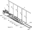
- a variant of this device is described in the figures 7th and 7f .
- It is a so-called “driven loop” reel. It is preferably fixed to the winch (1) and allows the traction belts (72-1, 72-2) to be oriented above the winch (1). It comprises a cylinder (49) freely fixed on an axis connected by two bearings (69) attached to two parallel toothed belts (75-5) supported by pulleys mounted on axes and bearings integral with the structure of the reel (2) .
- the two pulleys (49-1) furthest from the winch (1) determine, by their position, the maximum length of the loops (B) of the reel (2).
- Two other pulleys (49-3) are placed near the winch (1).
- the reel complication (2) presented in figures 7g and 7h , allows a longer length of traction belts (72) to be stored in a limited space.
- the unwinder (2) according to this arrangement comprises a train of five cylinders (49, 49-11, 49-12 and 49-13, 49-14). Three movable cylinders (49, 49-11, 49-12) are connected by bearings (69-11, 69-12, 69-13) attached to two parallel toothed belts (75-5). The other two cylinders (49-13, 49-14) are mounted on axes connected to the structure of the unwinder (2), and therefore fixed. All the cylinders (49, 49-11, 49-12, 49-13, 49-14) of this train turn freely on their respective axes.
- Each of the traction belts (72-1, 72-2) passes around each cylinder to be connected to a fixed connection point (69-1).
- the three movable cylinders (49, 49-11, 49-12) pull the traction belts (72-1, 72-2) towards the pulley (49 -1) furthest from the winch (1).
- the movable cylinders return to the fixed cylinders. The loops are thus permanently under control in a limited space.
- the cylinders (49, 49-11, 49-12 and 49-13, 49-14) are replaced by sets of several independent pulleys.
- a set of pulleys can include 2, 3 or more pulleys on the same axis.
- the traction belt (72) then winds alternately on the pulleys of two contiguous axes. More particularly, the traction belt (72) is wound on the first pulley of a first axle, then on the first pulley of the adjacent axle, then on the second pulley of the first axle, then on the second pulley of the first axle.
- the traction belt (72) can be arranged identically on another pair of two adjacent axes each comprising a set of pulleys.
- the number of pairs of adjacent axes can be adapted at will. It can be two, three, four or more. The reel (2) can thus accommodate significantly longer lengths of traction belts (72).
- This variant is also applicable to winches (1) provided with more than one traction belt (72). In this case, as many sets of pulleys as there are traction belts (72) must be provided.
- the “driven loop” wire feeder configuration keeps the traction belts (72-1, 72-2) close to the ceiling, preventing drooping loops (B).
- Such an arrangement facilitates the mobility of the structure comprising the winch (1) and the reel (2) placed in the scenic field, as well as its installation.
- FIG. 7i and 7 days An inverted configuration of the “driven loops” winch is shown schematically in the figures 7i and 7 days .
- the winch (1) is arranged lower than the load to be towed (Z), which can be held upwards by suspension means (not shown).
- the load (Z) denotes in such an inverted configuration the ceiling or a fixed element of the ceiling.
- the winch (1) is then secured to the load to be towed by any suitable fixing means. The activation of the winch (1) allows under these conditions to pull the winch (1) and the load associated with it upwards.
- the winch according to the present invention comprises a safety device.
- the figure 5 illustrates a winch operating safety device.
- a safety pin, free to rotate (89) provided with rollers integral with the axis is arranged parallel to the second drive axis (24), and fixed by its ends to the supports (15-2), (15-1) of the winch (1).
- the rollers integral with the safety pin (89) are arranged opposite the edges of the second drive pulleys (20-1), (20-2), at a distance close enough to be driven by a traction belt (72) if it comes to shift on its drive pulley.
- the surface of the safety pin (89) is also sufficiently close to the surface of the drive pulleys so as not to be driven by the traction belts (72-1), (72-2) in the event of of optimum operation and to be driven by the traction belts (72-1), (72-2) in the event of excess thickness, due for example the overlap of the notches of the drive belt on the teeth of the corresponding drive pulley.
- the function of the safety pin (89) is thus to maintain all the belts on the teeth of their respective pulleys.
- the safety axis (89) can include additional rollers facing the transmission pulley (20-3), located on the second drive axis (24), so as to keep the belt in position. intermediate transmission (75).
- the safety axis (89) is in contact with a sensor (88), which can be, for example, an electrical contact.
- a sensor can advantageously be fixed or integrated into a support (15-1), (15-2) of the winch (1) in contact with one end of the safety pin (89). If a pulley were to move sideways or if a traction belt (72-2), (72-1) were to overlap the flange of a second drive pulley (20-1), (20-2) or if the teeth of a traction belt (72-1), (72-2) rip against the teeth of the corresponding pulley, the incident would set the safety pin (89) in rotation and activate the sensor (88) . Activation of the sensor (88) may result from cutting off the power to the motor (11) or generating an alarm signal or both.
- the reel (2) described above can be equipped with a safety system equivalent to that described for the winch (1).
- one or more safety axes comprising rollers (44-1, 44-2) whose contact with the toothed belt initiates the rotation of the safety axes, can be integrated near the pulleys.
- Such pins can also serve as a spacer between the lateral supports of the reel (2).
- the size of the coils, drums, or brakes (12) of the winch (1), traditionally bulky, can be reduced by the arrangements described here.
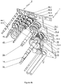
- the figures 9 , 9a and 9b represent the free pulleys (46-1; 46-2; 46-3; 46-4; 49; 49-11; 49-12; 49-13; 49-14) of the reel (2) according to various embodiments.
- the free pulleys (46-1; 46-2; 46-3; 46-4; 49; 49-11; 49-12; 49-13; 49-14) of the reel (2) can be independently one of the other smooth or notched, or have several different zones, like the drive pulleys (20-1, 20-2, 21-1, 21-2) of the winch (1).
- the free pulleys (46-1; 46-2; 46-3; 46-4; 49; 49-11; 49-12; 49-13; 49-14) of the reel (2) can be dedicated to the exclusive storage of traction belts (72).
- the free pulleys (46-1; 46-2; 46-3; 46-4; 49; 49-11; 49-12; 49-13; 49-14) of the reel (2) can alternatively allow the storage of one or more traction belts (72) combined with one or more cables (90).
- they may include several distinct surfaces, a portion of which is notched. They can alternatively be completely smooth.
- the reel (2) can be used to store one or more independent cables (90-1) separate from the traction belts (72), as shown schematically for example in the figures 11 and 11a .
- the free pulleys (46-1; 46-2; 46-3; 46-4; 49; 49-11; 49-12; 49-13; 49-14) of the reel (2) can be smooth , insofar as the load to be pulled is limited to the weight of the independent cable (90-1) to be stored in the reel (2), possibly combined with a low point load, less than about 30 Kg. They may be separate from the pulleys corresponding to the storage of traction belts (72).
- the independent cable (90-1) can be wound on the same pulleys as those used for the storage of the traction belts (72) or on pulleys integral with those used for the storage of the traction belts. (72).
- the storage of the independent cable (90-1) is in fact synchronized with that of the traction belts (72).
- the free pulleys (46-1; 46-2; 46-3; 46-4; 49; 49-11; 49-12; 49-13; 49-14) of the reel (2) comprise independent pulleys dedicated exclusively to the storage of independent cables (90-1).
- the surface of such pulleys can be completely smooth, it can include a notched portion, suitable for the traction of light loads, less than 30 Kg, preferably less than 10 Kg.
- the independent cable (90-1) can be a suspension cable for light loads, preferably less than about 30 kg.
- the independent cable (90-1) can be an electric cable.
- a traction belt (not shown) independent of the traction belts (72) driven by the winch (1), so as to avoid its stretching under the influence of its own weight or of its weight combined with the load to which it is connected.
- Electrical cables made of copper, are generally not suitable for pulling heavy loads.
- the traction belt associated with the independent cable (90-1) can be smooth or notched.
- the type of independent cable (90-1) thus wound is preferably of flat section.
- Such an arrangement can advantageously be used for the storage of independent cables (90-1) such as electric cables accompanied by a punctual electric device, such as a lamp or any other light lighting device.
- the independent cable (90-1) can alternatively allow the traction of non-electrified light loads such as banners, or decorative elements.
- the independent cable (90-1) can be a non-electric traction cable.
- the reel (2) can thus be used for the traction of light loads, independently of the traction belts (72) towed by the winch (1), which can remain synchronized with the winch (1).
- the independent cable or the set of independent cables (90-1) may have a circular, flat or mixed section, with flat surfaces and round surfaces.
- the independent cable (90-1) is of circular section, several turns can be wound around the circumference of one or more of the free pulleys of the reel (2).
- the diameter and the machining of the cylinders or pulleys remain independent of the storage length of the traction belts (72-1, 72-2).
- the storage length of a traction belt (72) depends primarily on the sum of the displacement of the loops.
- the storage length of the electric cables, whether they are associated with the traction belts (72) or independent (90-1) is also defined by the sum of the loops produced by the pulleys or cylinders (46-1; 46-2; 46-3; 46-4; 49; 49-11; 49-12; 49-13; 49-14).
- the end of the electric cable (90, 90-1) is connected to a fixed terminal (69-1).
- the figure 11 shows schematically a particular embodiment in which the independent cable (90-1) is not integral with a toothed traction belt (72).
- the independent cable (90-1) is connected to the pole (Z) via an electrical connector (72-7), but exerts on the pole (Z) no pulling force, or a force insufficient traction to lift the load.
- the winding and unwinding of the independent cable (90-1) is synchronized with the winch (1) thanks to the reel belt (75-5).
- One or more return pulleys (49-2, 49-4) can be provided on the path of the independent cable (90-1), either free in rotation or driven by the winch in a synchronized manner. These deflection pulleys (49-2, 49-4) can be smooth and not notched.
- a return pulley (49-4) can be advantageously driven by the winch (1) when the weight of the pole is not sufficient to spontaneously cause the unwinding of the independent cable (90-1).
- the synchronized drive of the return pulley (49-4) enables the independent cable (90-1) to be unwound synchronously with the traction belts (72). Winding of the independent cable (90-1) can be done without driving the deflection pulley (49-4), thanks to the transmission pulley (49-3) of the reel (1).
- the deflection pulley (49-4) is preferably a freewheel in the direction of winding of the independent cable (90-1).
- a tension spring can be included between the independent cable (90-1) and the pole (7) so as to compensate for any undesirable tensile forces on the pole.
- the independent cable (90-1) is then driven into the reel (2) in synchronization with the traction belt (s) (72).
- the figure 11a shows schematically an embodiment in which the independent cable (90-1) remains independent of the winch (1), while being able to be stored in the reel (2).
- the reel (2) comprises a toothed transmission belt (75-7), rotating in a closed loop around two transmission pulleys (49-30).
- the transmission belt (75-7) is driven around the transmission pulleys (49-30) by means of one or more traction means.
- the traction means may for example be gas jacks (49-32, 49-33, 49-34) calibrated so as to compensate for the weight of the independent cable (90-1) to be wound up. They can be defined so as not to exert a pulling force that is too great and likely to pull the pole (Z).
- the traction means may comprise an electric motor making it possible to exert a light traction force, preferably less than 30 kg, usually corresponding to the weight of cables possibly coupled to an electric device.
- At least one of the transmission pulleys (49-30) drives the reel cylinders (2), either directly or via one or more reduction pulleys (49-1) making it possible to establish the reports necessary to synchronize the storage of the independent cable (90-1) with the winding of the traction belts (72).
- One or more return pulleys (49-35) can be provided on the path of the independent cable (90-1), preferably free to rotate in both directions.
- the arrangements described here with a cable (90, 90-1), whether independent or combined with a traction belt (72) are applicable in the same way to all types of cables or cable assemblies.
- the same provisions can be applied for one or more computer cables, of the ethernet, internet, coaxial, shielded or protected type.
- the cables used include high voltage cables, known as power cables, allowing for example to supply one or more electric motors, low current cables, used to transmit information, video, audio, or other data. , and pneumatic cables, used in the control of automated devices tires.
- the independent cable (90-1) also includes traction cables suitable for low loads, such as steel cables.
- reel (2) is described below as being coupled to the winch presented in the present description, it can be used independently of the winch (1) or in combination with other types of winches. It is in particular considered that the reel (2) described here, whatever its embodiment, can be added and adapted to winches already installed, or else integrated into installations already in place.
- the reel used for the storage of one or more traction belts (72) driven by a winch comprises at least one toothed belt (75-5) driven by a transmission belt (75-6, 75-7 ).
- the toothed belt (s) (75-5) cooperate with at least one movable cylinder (49) (49-11), (49-12), and optionally with at least one fixed cylinder (49-13), (49-14 ) rotating freely on an axis (69, 69-11, 69-12, 69-13).
- the unwinder (2) can further include one or more return pulleys (49-4) making it possible to wind and unwind a cable (90-1) independent of the traction belts (72).
- the transmission belt (75-6, 75-7) can be driven by the winch used for the traction of the traction belt (s) (72), or else by one or more traction means (49-32, 49- 33, 49-34) independent of the winch.
- the unwinder (2) is characterized in that the movable cylinder (49) (49-11), (49-12) and fixed (49-13), (49-14) are configured so as to wind the belt or belts (72) or an independent cable (90-1), or a set consisting of traction belts (72) and an independent cable (90-1), in the reel (2), synchronously with the winch.
- the reel (2) can alternatively comprise at least a first set of pulleys (46-1 to 46-4) mounted to rotate freely on a support shaft (45) and at least a second set of pulleys (51, 52, 53, 54) integral with a relay axis (43).
- the pulleys (46-1 to 46-4) of the first set of pulleys are each driven by a transmission belt (75-1), (72-2), (75-3), (75-4), connected to each of the pulleys (51, 52, 53, 54) of the second set of pulleys.
- the relay axis (43) can be driven in rotation by the winch used for the traction of the traction belt (s) (72) or else by one or more traction means (49-32, 49-33, 49-34 ) independent of the winch.
- the pulleys driven by the relay axis (43) have different diameters from each other.
- the pulleys mounted to rotate freely on the support shaft (45) preferably all have the same diameter.
- the two traction belts (72-1), (72-2) can be reinforced by metal strands (80). One of their ends can then be freely attached to an electrical outlet and lead the current to the other end of the traction belts (72-1), (72-2), located on the place where the load is gripped ( Z).
- the metal strands (80) can conduct low voltage current.
- the metal strands (80) can also be used as a security element, as shown diagrammatically in figures 10a and 10b .
- an electric line is created continuous connecting all the strands (80).
- This electrical line can be connected to an electrical circuit of the “Wheatstone bridge” type so as to be able to measure the variation in its electrical characteristics.
- FIG. 10a An example of such a circuit is shown schematically on figure 10a . It comprises in particular a differential sensor (CD), a first resistor (R1), a second resistor (R2) and a third resistor (R3).
- the first resistor (R1) is connected to a terminal of the differential sensor (CD) and to one end of the power line.
- the third resistor (R3) is connected to the other end of the electrical circuit and to the other terminal of the differential sensor (CD).
- Other electrical circuits are also possible.
- the electrical circuit then makes it possible to detect, for example, a break in the traction belt (72). It can also detect its excessive elongation indicating an overload.
- the metal strands (80) are electrically connected to each other using electrical connections (80-1).
- the length of the electric line thus created is greater and allows better measurement accuracy of any failures.
- FIG. 9 shows a drive pulley (20-1) adapted to drive a traction belt (72), flanked by two conductors (90).
- the rolling surface of such a drive pulley then comprises several zones.
- a drive zone (E) in contact with the traction belt (72) and one or more passage zones (P), allowing the passage of the conductor or conductors associated with the traction belt (72).
- the driving zone has teeth adapted to the driving of the traction belt (72), and the passage zones remain smooth.
- the traction zone (E) can be reduced to one or more extra thickness in contact with the traction belt (72).
- the traction zone (E) can for example be central and the passage zones (P) can be arranged on either side.
- the training zone (E) is in a lateral position and where the passage zones are grouped together in a single zone (P). This embodiment has the great advantage of combining the mechanical qualities of the toothed belt with the electrical qualities of the conductors.
- the pulley shown in figure 9 as part of the winch (1) can be used in a reel (2) synchronized with the winch, as described in more detail below.
- the scenic winch can be assigned to move a scenery pole (Z).
- this pole (Z) a few meters in length and several attachment points are needed to ensure smooth movement.
- a traction belt (72) At each attachment point is attached a traction belt (72).
- a pulley large enough to accommodate all of the belts can be used.
- the unwinder (2) then only contains a train of pulleys driven by the second drive shaft (24).
- One end of the traction belts (72) is connected, if necessary, to an electrical outlet.
- the winch (1) raises the pole (Z)
- the traction belts (72) move in parallel and each form a loop (B) in the reel (2) of increasing circumference.
- the pole (Z) goes down, the loops (B) are reduced.
- the loops (B) can be oriented in a direction different from the vertical, for example thanks to an inclined plane on which they can rest and be moved away from the stage.
- An inclined plane may for example take the form of a sliding wall and / or a slide.
- the traction belt (72) is preferably a toothed belt, in the various embodiments described, because of its mechanical qualities and the precision of the movements. For there to be a positioning error, it is necessary that the teeth have ripped on the drive pulleys, which is very unlikely in the context of this invention.
- the drive pulleys must necessarily be compatible with the chosen traction means and its characteristics.
- toothed belts do not have the same admissible radius of curvature in both directions of bending. For this reason, the tensioner pulleys (41) are larger than the drive pulleys.
Applications Claiming Priority (1)
| Application Number | Priority Date | Filing Date | Title |
|---|---|---|---|
| CH00135/19A CH715818A1 (fr) | 2019-02-06 | 2019-02-06 | Treuil scénique à courroies crantées et courroie crantée adaptée. |
Publications (1)
| Publication Number | Publication Date |
|---|---|
| EP3693324A1 true EP3693324A1 (de) | 2020-08-12 |
Family
ID=67551031
Family Applications (1)
| Application Number | Title | Priority Date | Filing Date |
|---|---|---|---|
| EP20155861.6A Withdrawn EP3693324A1 (de) | 2019-02-06 | 2020-02-06 | Elektrozug mit synchronriemen |
Country Status (2)
| Country | Link |
|---|---|
| EP (1) | EP3693324A1 (de) |
| CH (1) | CH715818A1 (de) |
Citations (7)
| Publication number | Priority date | Publication date | Assignee | Title |
|---|---|---|---|---|
| DE19613037A1 (de) | 1996-04-01 | 1997-10-02 | H & B Metalltechnik Huelserman | Transportabler Punktzug |
| EP1760028A1 (de) * | 2005-09-06 | 2007-03-07 | Elex Italia S.r.l. | Hebeeinrichtung ohne Maschinenraum für Personen und Gütern. |
| EP2157334A1 (de) | 2008-07-14 | 2010-02-24 | komax Holding AG | Vorrichtung zum linearen Bewegen eines Schlittens |
| EP2248756A1 (de) * | 2006-04-28 | 2010-11-10 | Electronic Theatre Controls, Inc. | Hebesystem |
| WO2013075751A1 (en) * | 2011-11-25 | 2013-05-30 | Kone Corporation | Power transmission belt |
| EP2625131A1 (de) | 2010-10-06 | 2013-08-14 | Demag Cranes & Components GmbH | Hebezeug mit einem zahnriemen als tragmittel |
| US20160045837A1 (en) * | 2014-08-12 | 2016-02-18 | Charles B. Shatzkin | Variable Speed System to Motorize Counterweight Line Sets |
Family Cites Families (2)
| Publication number | Priority date | Publication date | Assignee | Title |
|---|---|---|---|---|
| EP2810911A1 (de) * | 2013-06-05 | 2014-12-10 | Kone Corporation | Antriebsmaschine für einen Aufzug sowie ein Aufzug |
| CN204281138U (zh) * | 2014-05-28 | 2015-04-22 | 佑图物理应用科技发展(武汉)有限公司 | 一种用于演播室、舞台的带有收缆装置的吊机 |
-
2019
- 2019-02-06 CH CH00135/19A patent/CH715818A1/fr unknown
-
2020
- 2020-02-06 EP EP20155861.6A patent/EP3693324A1/de not_active Withdrawn
Patent Citations (7)
| Publication number | Priority date | Publication date | Assignee | Title |
|---|---|---|---|---|
| DE19613037A1 (de) | 1996-04-01 | 1997-10-02 | H & B Metalltechnik Huelserman | Transportabler Punktzug |
| EP1760028A1 (de) * | 2005-09-06 | 2007-03-07 | Elex Italia S.r.l. | Hebeeinrichtung ohne Maschinenraum für Personen und Gütern. |
| EP2248756A1 (de) * | 2006-04-28 | 2010-11-10 | Electronic Theatre Controls, Inc. | Hebesystem |
| EP2157334A1 (de) | 2008-07-14 | 2010-02-24 | komax Holding AG | Vorrichtung zum linearen Bewegen eines Schlittens |
| EP2625131A1 (de) | 2010-10-06 | 2013-08-14 | Demag Cranes & Components GmbH | Hebezeug mit einem zahnriemen als tragmittel |
| WO2013075751A1 (en) * | 2011-11-25 | 2013-05-30 | Kone Corporation | Power transmission belt |
| US20160045837A1 (en) * | 2014-08-12 | 2016-02-18 | Charles B. Shatzkin | Variable Speed System to Motorize Counterweight Line Sets |
Also Published As
| Publication number | Publication date |
|---|---|
| CH715818A1 (fr) | 2020-08-14 |
Similar Documents
| Publication | Publication Date | Title |
|---|---|---|
| EP2459835B1 (de) | Fallstoppübertragungsvorrichtung für eine transporttür mit einem flexiblem vorhang | |
| EP2178784A1 (de) | Winde zum ziehen von kabeln, insbesondere für offshore verwendete synthetische kabel | |
| FR2823734A1 (fr) | Installation d'ascenseur pourvue de moyens d'entrainement et de moyens de suspension independants | |
| EP3646425B1 (de) | Vorrichtung und verfahren zum greifen eines kabels mittels einer spannungsentlastungskabelklemme | |
| EP0009058B1 (de) | Aufhängevorrichtung für eine Bühne zur Instandhaltung von Fassaden | |
| FR2513236A1 (fr) | Treuil mobile a cable | |
| FR2532924A1 (fr) | Systeme d'entrainement pour des appareils elevateurs a cables metalliques | |
| WO2001038217A1 (fr) | Dispositif d'equilibrage d'efforts pour un treuil a deux cables de traction et treuil muni d'un tel dispositif | |
| CA2470266A1 (fr) | Systeme de levage et de stabilisation d'un support de charge suspendu | |
| FR2676720A1 (fr) | Dispositif enrouleur-derouleur de cables, notamment de cables de levage pour ponts roulants. | |
| EP3693324A1 (de) | Elektrozug mit synchronriemen | |
| WO2011001503A1 (ja) | 張線器 | |
| FR2949627A1 (fr) | Procede pour verifier l'etat d'un frein d'un mecanisme commande par un convertisseur de frequence ou autre controleur | |
| FR2652572A1 (fr) | Procede d'enroulement en double d'un cable ou analogue sur la surface externe d'un touret. | |
| CN110844712B (zh) | 一种岸电线缆管理装置 | |
| FR2551255A1 (fr) | Dispositif de cablage de fils d'armure autour d'une ame d'un cable, et procede mis en oeuvre par ce dispositif | |
| FR2552412A1 (fr) | Dispositif d'alimentation destine a guider un cable sur un tambour d'enroulement | |
| EA032366B1 (ru) | Навивочная машина для навивки волоконно-оптического кабеля | |
| FR2858987A1 (fr) | Procede de montage d'un hauban | |
| EP0671195B1 (de) | Motorisierte Vorrichtung zum Handhaben von hängenden Prospektzügen und dergleichen | |
| FR2811652A1 (fr) | Machine de palettisation automatique de produits cylindriques allonges | |
| FR2773792A1 (fr) | Unite de levage de type palan | |
| FR2657802A1 (fr) | Centrale de devidage de fil de soudure. | |
| FR2778505A1 (fr) | Procede de remplacement de cables aeriens et systeme de protection autoportee pour la mise en oeuvre du procede | |
| RU151100U1 (ru) | Навивочная машина для навивки волоконно-оптического кабеля |
Legal Events
| Date | Code | Title | Description |
|---|---|---|---|
| PUAI | Public reference made under article 153(3) epc to a published international application that has entered the european phase |
Free format text: ORIGINAL CODE: 0009012 |
|
| STAA | Information on the status of an ep patent application or granted ep patent |
Free format text: STATUS: THE APPLICATION HAS BEEN PUBLISHED |
|
| AK | Designated contracting states |
Kind code of ref document: A1 Designated state(s): AL AT BE BG CH CY CZ DE DK EE ES FI FR GB GR HR HU IE IS IT LI LT LU LV MC MK MT NL NO PL PT RO RS SE SI SK SM TR |
|
| AX | Request for extension of the european patent |
Extension state: BA ME |
|
| STAA | Information on the status of an ep patent application or granted ep patent |
Free format text: STATUS: REQUEST FOR EXAMINATION WAS MADE |
|
| 17P | Request for examination filed |
Effective date: 20210202 |
|
| RBV | Designated contracting states (corrected) |
Designated state(s): AL AT BE BG CH CY CZ DE DK EE ES FI FR GB GR HR HU IE IS IT LI LT LU LV MC MK MT NL NO PL PT RO RS SE SI SK SM TR |
|
| STAA | Information on the status of an ep patent application or granted ep patent |
Free format text: STATUS: THE APPLICATION IS DEEMED TO BE WITHDRAWN |
|
| 18D | Application deemed to be withdrawn |
Effective date: 20230901 |