EP3693314A1 - Elevator car and door motion monitoring - Google Patents
Elevator car and door motion monitoring Download PDFInfo
- Publication number
- EP3693314A1 EP3693314A1 EP19215386.4A EP19215386A EP3693314A1 EP 3693314 A1 EP3693314 A1 EP 3693314A1 EP 19215386 A EP19215386 A EP 19215386A EP 3693314 A1 EP3693314 A1 EP 3693314A1
- Authority
- EP
- European Patent Office
- Prior art keywords
- movement
- door
- elevator car
- along
- axes
- Prior art date
- Legal status (The legal status is an assumption and is not a legal conclusion. Google has not performed a legal analysis and makes no representation as to the accuracy of the status listed.)
- Granted
Links
Images

Classifications
-
- B—PERFORMING OPERATIONS; TRANSPORTING
- B66—HOISTING; LIFTING; HAULING
- B66B—ELEVATORS; ESCALATORS OR MOVING WALKWAYS
- B66B1/00—Control systems of elevators in general
- B66B1/24—Control systems with regulation, i.e. with retroactive action, for influencing travelling speed, acceleration, or deceleration
- B66B1/28—Control systems with regulation, i.e. with retroactive action, for influencing travelling speed, acceleration, or deceleration electrical
- B66B1/32—Control systems with regulation, i.e. with retroactive action, for influencing travelling speed, acceleration, or deceleration electrical effective on braking devices, e.g. acting on electrically controlled brakes
-
- B—PERFORMING OPERATIONS; TRANSPORTING
- B66—HOISTING; LIFTING; HAULING
- B66B—ELEVATORS; ESCALATORS OR MOVING WALKWAYS
- B66B5/00—Applications of checking, fault-correcting, or safety devices in elevators
- B66B5/0087—Devices facilitating maintenance, repair or inspection tasks
-
- B—PERFORMING OPERATIONS; TRANSPORTING
- B66—HOISTING; LIFTING; HAULING
- B66B—ELEVATORS; ESCALATORS OR MOVING WALKWAYS
- B66B5/00—Applications of checking, fault-correcting, or safety devices in elevators
- B66B5/0006—Monitoring devices or performance analysers
- B66B5/0018—Devices monitoring the operating condition of the elevator system
-
- B—PERFORMING OPERATIONS; TRANSPORTING
- B66—HOISTING; LIFTING; HAULING
- B66B—ELEVATORS; ESCALATORS OR MOVING WALKWAYS
- B66B1/00—Control systems of elevators in general
- B66B1/02—Control systems without regulation, i.e. without retroactive action
- B66B1/06—Control systems without regulation, i.e. without retroactive action electric
- B66B1/14—Control systems without regulation, i.e. without retroactive action electric with devices, e.g. push-buttons, for indirect control of movements
- B66B1/22—Control systems without regulation, i.e. without retroactive action electric with devices, e.g. push-buttons, for indirect control of movements with means for taking account of delayed calls
-
- B—PERFORMING OPERATIONS; TRANSPORTING
- B66—HOISTING; LIFTING; HAULING
- B66B—ELEVATORS; ESCALATORS OR MOVING WALKWAYS
- B66B1/00—Control systems of elevators in general
- B66B1/34—Details, e.g. call counting devices, data transmission from car to control system, devices giving information to the control system
- B66B1/3415—Control system configuration and the data transmission or communication within the control system
- B66B1/3446—Data transmission or communication within the control system
-
- B—PERFORMING OPERATIONS; TRANSPORTING
- B66—HOISTING; LIFTING; HAULING
- B66B—ELEVATORS; ESCALATORS OR MOVING WALKWAYS
- B66B1/00—Control systems of elevators in general
- B66B1/34—Details, e.g. call counting devices, data transmission from car to control system, devices giving information to the control system
- B66B1/36—Means for stopping the cars, cages, or skips at predetermined levels
- B66B1/40—Means for stopping the cars, cages, or skips at predetermined levels and for correct levelling at landings
-
- B—PERFORMING OPERATIONS; TRANSPORTING
- B66—HOISTING; LIFTING; HAULING
- B66B—ELEVATORS; ESCALATORS OR MOVING WALKWAYS
- B66B13/00—Doors, gates, or other apparatus controlling access to, or exit from, cages or lift well landings
- B66B13/24—Safety devices in passenger lifts, not otherwise provided for, for preventing trapping of passengers
-
- B—PERFORMING OPERATIONS; TRANSPORTING
- B66—HOISTING; LIFTING; HAULING
- B66B—ELEVATORS; ESCALATORS OR MOVING WALKWAYS
- B66B5/00—Applications of checking, fault-correcting, or safety devices in elevators
- B66B5/0006—Monitoring devices or performance analysers
- B66B5/0018—Devices monitoring the operating condition of the elevator system
- B66B5/0025—Devices monitoring the operating condition of the elevator system for maintenance or repair
-
- B—PERFORMING OPERATIONS; TRANSPORTING
- B66—HOISTING; LIFTING; HAULING
- B66B—ELEVATORS; ESCALATORS OR MOVING WALKWAYS
- B66B5/00—Applications of checking, fault-correcting, or safety devices in elevators
- B66B5/0006—Monitoring devices or performance analysers
- B66B5/0037—Performance analysers
-
- G—PHYSICS
- G06—COMPUTING OR CALCULATING; COUNTING
- G06F—ELECTRIC DIGITAL DATA PROCESSING
- G06F3/00—Input arrangements for transferring data to be processed into a form capable of being handled by the computer; Output arrangements for transferring data from processing unit to output unit, e.g. interface arrangements
-
- B—PERFORMING OPERATIONS; TRANSPORTING
- B66—HOISTING; LIFTING; HAULING
- B66B—ELEVATORS; ESCALATORS OR MOVING WALKWAYS
- B66B5/00—Applications of checking, fault-correcting, or safety devices in elevators
Definitions
- Elevator systems include elevator cars that move through a hoistway to carry passengers or cargo between different levels of a building. Elevator cars include doors that open and close when the car is parked at a landing to allow an individual to enter or exit the car. Elevator car doors are associated with a number of issues that occur and require maintenance or service personnel to visit the site of the elevator system. Remotely monitoring elevator door functionality facilitates directing appropriate personnel to any sites that require service.
- the accelerometer is a MEMs accelerometer.
- the processor is supported on the door.
- the output includes an indication of movement of the door along at least two axes
- the movement of the door includes intended movement along one of the two axes
- the at least one characteristic includes an indication of any movement of the door along another of the two axes
- the two axes are transverse to each other.
- the at least one characteristic corresponds to at least one of a smoothness and a consistency of the intended movement along the one of the two axes.
- the processor provides an output reporting the location of the elevator car and the at least one characteristic of the movement of the door.
- the at least one characteristic is a motion profile corresponding to the movement of the door between closed and open positions.
- sensing the movement of the door includes sensing the movement along at least two axes, the movement of the door includes intended movement along one of the two axes, the at least one characteristic includes an indication of any movement of the door along another of the two axes, and the two axes are transverse to each other.
- the at least one characteristic includes any vibration of the door during the movement of the door.
- the at least one characteristic is a motion profile corresponding to the movement of the door between closed and open positions.
- FIG. 1 schematically illustrates selected portions of an elevator system 20.
- An elevator car 22 is situated within a hoistway 24 in a known manner.
- a plurality of landing doors 26 are situated at landings serviced by the elevator car 22.
- the elevator car 22 includes doors 28.
- a sensor device 30 is supported on at least one of the doors 28. Although schematically shown supported on the door panel of the illustrated door 28, the sensor device 30 may be situated on any portion of the door assembly including, for example a door hanger or a door frame.
- the term "door” as used in this document should be understood to include the entire door system or assembly and not be limited to a particular portion of the door.
- the sensor device 30 includes a sensor 32 and a processor 34.
- the sensor device 30 wirelessly communicates information pertaining to movement of the doors 28 and the elevator car 22, which is provided to a remote monitoring center 40.
- the sensor device 30 may wirelessly communicate with another communication device at the site of the elevator system 20 that is responsible for relaying the information from the sensor device 30 to the remote monitoring center 40 or may communicate directly to the remote monitoring center 40.
- the sensor 32 is capable of detecting movement along three axes 42, 44 and 46.
- the sensor 32 provides an output including an indication of movement of the doors 28 along at least two axes.
- movement along the axis 42 corresponds to movement in a desired direction of door movement as shown at 48.
- Door movement along the axis 44 or the axis 46 corresponds to vibration or other undesired movement of the doors 28.
- the sensor 32 also provides an indication of movement of the elevator car 22 along at least one of the axes.
- the axis 44 corresponds to vertical movement of the elevator car 22 within the hoistway 24 in the illustrated example.
- the illustrated example sensor 32 is capable of providing information regarding movement of the elevator car 22 along any of the three axes 42, 44 and 46.
- the processor 34 receives the output from the sensor 32 and determines at least one characteristic of the movement of the doors 28. For example, the processor determines whether there was any vibration of the doors 28 during the movement of the doors.
- the car doors 28 include a known coupler (not illustrated) so that when the elevator car 22 is situated at one of the landings, the landing doors 26 move with the car doors 28.
- the output regarding movement of the doors 28 provided by the sensor 32 provides information regarding the corresponding movement of the landing doors 26.
- it will be associated with one of the landing doors 26, rather than the elevator car doors 28.
- the output from the sensor 32 provides an indication of such movement.
- the characteristic of door movement in the output provided by the processor 34 in some embodiments corresponds to at least one of the smoothness and consistency of the intended movement of the doors 28 along the axis 42.
- the characteristic of door movement corresponds to a motion profile describing the movement of the doors 28 between closed and open positions. Such a motion profile may include an indication of acceleration, constant velocity motion, deceleration, vibration, and any other type of motion as the doors 28 travel from a fully closed position to a fully open position and then back again to the fully closed position.
- the senor 32 is an accelerometer.
- Some embodiments include a microelectromechanical (MEMs) accelerometer.
- the processor 34 associated with the sensor 32 is supported on the same elevator car door as the sensor 32. With such a sensor and processor, it is a relatively straightforward or simple task to install the sensor device 30 without requiring any complicated wiring or connections with other portions of the elevator system 20.
- the sensor device 30 may operate in a transmit-only mode and rely purely upon battery power because it does not require any receiving capability to receive information from other parts of the elevator system 20. This approach provides a low-cost solution to remotely monitor any issues associated with movement of the elevator car 22 and the doors 28 and 26.
- the sensor device 30 has the capability of receiving information or signals from other devices.
- Some embodiments include line-based connections to provide power to the sensor device 30 or to facilitate communications between the sensor device 30 and another device.
- Another feature of the output from the processor 34 is that it provides an indication of a location of the elevator car 22 where the sensed movement of the car doors 28 occurs.
- the processor 34 uses information from the sensor 32 regarding movement of the elevator car 22 to determine its position within the hoistway 24. Having information regarding the location of the elevator car 22 allows for identifying a specific landing where a door-related problem occurs so that maintenance personnel dispatched to the site of the elevator system 20 can more efficiently and economically address the issue.
- Figure 3 is a flowchart diagram 50 summarizing an example approach of monitoring the elevator system 20 and incorporating location or position information into the output regarding the sensed movement.
- the sensor 32 detects elevator car movement, for example, along the axis 44.
- the sensor 32 detects that the elevator car 22 has stopped.
- the processor 34 determines a location of the elevator car 22 while it is stopped.
- the example embodiment includes accommodations for slight variations in the parked or stopped position of the elevator car 22 at a landing.
- the car may not be exactly leveled during one stop when the location of the elevator car 22 is determined and during another stop it may be exactly level.
- the processor 34 is configured or suitably programmed to allow for differences in stop positions within predetermined ranges to be considered as the same landing or parking position.
- the elevator car doors 28 will open.
- the sensor device 30 detects movement of the elevator car doors 28.
- the processor 34 determines whether the current location of the elevator car 22 corresponds to a known landing at 60. If the current position of the elevator car does not correspond to a known landing, the processor 34 identifies that location as another landing along the hoistway 24.
- the processor 34 provides an output including an indication of at least one characteristic of the door movement and a corresponding location of the elevator car 22. That output provided at 62 may be communicated to the remote monitoring sensor 40 where it is available for further analysis.
- FIG. 4 schematically illustrates a logical flow for identifying landings along the hoistway 24.
- the elevator car 22 begins at a position relatively low in the hoistway corresponding to the second landing from the bottom of the hoistway 24, which may be a first floor or ground floor of a building. This position of the elevator car is shown at 70 in Figure 4 .
- the elevator car 22 travels upward in the hoistway 24 and stops at a location indicated at 74 corresponding to the third floor of the building.
- the sensor 32 Since that location is higher than the location shown at 70, the sensor 32 will generate an output indicating upward movement along the axis 44.
- the processor 34 receives that output from the sensor 32 and automatically assigns a first floor landing designation to that location and assigns a basement or lower level designation to the originally parked position. Then at 76, the elevator car 22 travels down and stops at a new location between those that have been already identified. The car doors 28 open at this location indicating that it is a landing. Since the location shown at 78 where the elevator car 22 is now parked is between the two previously identified landings, it is assigned the first floor designation and the location previously identified as the first floor at 74 is changed to be identified as the second floor.
- the elevator car 22 moves upward again and stops at the location that is now identified as the second floor as shown at 82 in Figure 4 . From that location as shown at 84, the elevator car 22 travels upward and stops at a higher location shown at 86. As this is the highest location currently known to the processor 34, it assigns a higher floor designation than the highest one previously identified. At 86, the current location of the elevator car is assigned a third floor landing designation. At 88, the elevator car 22 moves downward and stops at the lowest level as shown at 90 in Figure 4 . This is a new location to the processor 34 so it identifies that location as the basement or lower level having a designation zero in Figure 4 . Each of the landings above that position has its designation increased by one.
- Any further stops of the elevator car 22 at any of the landings represented in Figure 4 will be a stop at a location of an identified landing.
- the processor 34 need not update any information under those circumstances.
- This approach to identifying landings along the hoistway 24 may be completed by the processor 34 supported on the elevator car door 28 without requiring any external input to the sensor device 30. Instead, the motion information from the sensor 32 allows the processor 34 to make determinations regarding the location of the elevator car 22 relative to any previously identified locations.
- the processor 34 may observe the output from the sensor 32 and remove any bias or offset along an appropriate one of the axes 42, 44 or 46. For example, when the elevator car is parked at a landing and remains stationary, any offset in the vertical direction may be removed. Appropriate conditions for removing any offset in the directions corresponding to the other axes 42 and 46 are useful for eliminating any offset or drift in those directions.
- One feature of the illustrated example arrangement is that it allows for remotely monitoring an elevator system including identifying specific elevator door movement characteristics at specific locations along the hoistway 24.
- a single sensor device 30 supported on an elevator car door provides information regarding elevator car door movement and elevator car movement.
- the wireless communication and battery powered features make the example approach economical and efficient.
Landscapes
- Engineering & Computer Science (AREA)
- Automation & Control Theory (AREA)
- Theoretical Computer Science (AREA)
- Computer Networks & Wireless Communication (AREA)
- Human Computer Interaction (AREA)
- Physics & Mathematics (AREA)
- General Engineering & Computer Science (AREA)
- General Physics & Mathematics (AREA)
- Indicating And Signalling Devices For Elevators (AREA)
- Elevator Door Apparatuses (AREA)
Abstract
Description
- Elevator systems include elevator cars that move through a hoistway to carry passengers or cargo between different levels of a building. Elevator cars include doors that open and close when the car is parked at a landing to allow an individual to enter or exit the car. Elevator car doors are associated with a number of issues that occur and require maintenance or service personnel to visit the site of the elevator system. Remotely monitoring elevator door functionality facilitates directing appropriate personnel to any sites that require service.
- There are known systems for remotely monitoring elevator system performance. One drawback associated with some such systems is that they require some integration with the elevator control components. Another example drawback presented by some approaches is that the monitoring hardware can be difficult to install.
- An illustrative example elevator sensor device includes at least one sensor supported on a door of an elevator car. The sensor provides an output including an indication of at least movement of the door along at least one axis and movement of the elevator car along at least one axis. A processor associated with the at least one sensor receives the output and determines at least one characteristic of the movement of the door based on the indication of the movement of the door. The processor also determines a location of the elevator car where the movement of the door occurs based on the indication of movement of the elevator car.
- In an example embodiment having one or more features of the sensor device of the previous paragraph, the at least one sensor comprises an accelerometer that senses motion along three perpendicular axes.
- In an example embodiment having one or more features of the sensor device of any of the previous paragraphs, the accelerometer is a MEMs accelerometer.
- In an example embodiment having one or more features of the sensor device of any of the previous paragraphs, the processor is supported on the door.
- In an example embodiment having one or more features of the sensor device of any of the previous paragraphs, the output includes an indication of movement of the door along at least two axes, the movement of the door includes intended movement along one of the two axes, the at least one characteristic includes an indication of any movement of the door along another of the two axes, and the two axes are transverse to each other.
- In an example embodiment having one or more features of the sensor device of any of the previous paragraphs, the at least one characteristic includes any vibration of the door during the movement of the door.
- In an example embodiment having one or more features of the sensor device of any of the previous paragraphs, the at least one characteristic corresponds to at least one of a smoothness and a consistency of the intended movement along the one of the two axes.
- In an example embodiment having one or more features of the sensor device of any of the previous paragraphs, the processor determines the location of the elevator car based on identifying a plurality of landing locations where the elevator car stops after moving in a direction along the at least one axis and where the door moves along at least one of the at least two axes; and determining whether the location of the elevator car corresponds to one of the identified landing locations.
- In an example embodiment having one or more features of the sensor device of any of the previous paragraphs, the processor provides an output reporting the location of the elevator car and the at least one characteristic of the movement of the door.
- In an example embodiment having one or more features of the sensor device of any of the previous paragraphs, the at least one characteristic is a motion profile corresponding to the movement of the door between closed and open positions.
- An illustrative example embodiment of a method includes sensing movement of a door of an elevator car along at least one axis by a sensor supported on the door; sensing movement of the elevator car along at least one axis by the sensor supported on the door; determining at least one characteristic of the movement of the door based on the sensed movement of the door; and determining a location of the elevator car where the movement of the door occurs based on the sensed movement of the elevator car.
- In an example embodiment having one or more features of the method of the previous paragraph, the at least one sensor comprises an accelerometer that senses motion along three perpendicular axes.
- In an example embodiment having one or more features of the method of any of the previous paragraphs, the accelerometer is a MEMs accelerometer.
- In an example embodiment having one or more features of the method of any of the previous paragraphs, sensing the movement of the door includes sensing the movement along at least two axes, the movement of the door includes intended movement along one of the two axes, the at least one characteristic includes an indication of any movement of the door along another of the two axes, and the two axes are transverse to each other.
- In an example embodiment having one or more features of the method of any of the previous paragraphs, the at least one characteristic includes any vibration of the door during the movement of the door.
- In an example embodiment having one or more features of the method of any of the previous paragraphs, the at least one characteristic corresponds to at least one of a smoothness and a consistency of the intended movement along the one of the two axes.
- In an example embodiment having one or more features of the method of any of the previous paragraphs, determining the location of the elevator car comprises identifying a plurality of landing locations where the elevator car stops after moving in a direction along the at least one axis and where the door moves along at least one of the at least two axes; and determining whether the location of the elevator car corresponds to one of the identified landing locations.
- An example embodiment having one or more features of the method of any of the previous paragraphs includes reporting the location of the elevator car and the at least one characteristic of the movement of the door to a location remote from a site of the elevator car.
- In an example embodiment having one or more features of the method of any of the previous paragraphs, the at least one characteristic is a motion profile corresponding to the movement of the door between closed and open positions.
- The various features and advantages of an example embodiment will become apparent to those skilled in the art from the following detailed description. The drawings that accompany the detailed description can be briefly described as follows.
-
-
Figure 1 schematically illustrates selected portions of an elevator system. -
Figure 2 schematically illustrates selected features of an example elevator car. -
Figure 3 is a flowchart diagram summarizing an example monitoring approach. -
Figure 4 graphically illustrates a floor mapping strategy. -
Figure 1 schematically illustrates selected portions of anelevator system 20. Anelevator car 22 is situated within ahoistway 24 in a known manner. A plurality oflanding doors 26 are situated at landings serviced by theelevator car 22. - As shown in
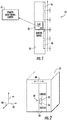
Figure 2 , theelevator car 22 includesdoors 28. Asensor device 30 is supported on at least one of thedoors 28. Although schematically shown supported on the door panel of the illustrateddoor 28, thesensor device 30 may be situated on any portion of the door assembly including, for example a door hanger or a door frame. The term "door" as used in this document should be understood to include the entire door system or assembly and not be limited to a particular portion of the door. - The
sensor device 30 includes asensor 32 and aprocessor 34. Thesensor device 30 wirelessly communicates information pertaining to movement of thedoors 28 and theelevator car 22, which is provided to aremote monitoring center 40. Although not specifically illustrated, thesensor device 30 may wirelessly communicate with another communication device at the site of theelevator system 20 that is responsible for relaying the information from thesensor device 30 to theremote monitoring center 40 or may communicate directly to theremote monitoring center 40. - The
sensor 32 is capable of detecting movement along threeaxes sensor 32 provides an output including an indication of movement of thedoors 28 along at least two axes. In the example ofFigure 2 , movement along theaxis 42 corresponds to movement in a desired direction of door movement as shown at 48. Door movement along theaxis 44 or theaxis 46 corresponds to vibration or other undesired movement of thedoors 28. - The
sensor 32 also provides an indication of movement of theelevator car 22 along at least one of the axes. Theaxis 44 corresponds to vertical movement of theelevator car 22 within thehoistway 24 in the illustrated example. The illustratedexample sensor 32 is capable of providing information regarding movement of theelevator car 22 along any of the threeaxes - The
processor 34 receives the output from thesensor 32 and determines at least one characteristic of the movement of thedoors 28. For example, the processor determines whether there was any vibration of thedoors 28 during the movement of the doors. - The
car doors 28 include a known coupler (not illustrated) so that when theelevator car 22 is situated at one of the landings, thelanding doors 26 move with thecar doors 28. The output regarding movement of thedoors 28 provided by thesensor 32 provides information regarding the corresponding movement of thelanding doors 26. Often, if there is a problem with one of the doors of theelevator system 20, it will be associated with one of thelanding doors 26, rather than theelevator car doors 28. Of course, there are situations in which one or both of theelevator car doors 28 are not moving smoothly or consistently in a desired manner and the output from thesensor 32 provides an indication of such movement. - The characteristic of door movement in the output provided by the
processor 34 in some embodiments corresponds to at least one of the smoothness and consistency of the intended movement of thedoors 28 along theaxis 42. In some embodiments the characteristic of door movement corresponds to a motion profile describing the movement of thedoors 28 between closed and open positions. Such a motion profile may include an indication of acceleration, constant velocity motion, deceleration, vibration, and any other type of motion as thedoors 28 travel from a fully closed position to a fully open position and then back again to the fully closed position. - In an example embodiment the
sensor 32 is an accelerometer. Some embodiments include a microelectromechanical (MEMs) accelerometer. Theprocessor 34 associated with thesensor 32 is supported on the same elevator car door as thesensor 32. With such a sensor and processor, it is a relatively straightforward or simple task to install thesensor device 30 without requiring any complicated wiring or connections with other portions of theelevator system 20. Thesensor device 30 may operate in a transmit-only mode and rely purely upon battery power because it does not require any receiving capability to receive information from other parts of theelevator system 20. This approach provides a low-cost solution to remotely monitor any issues associated with movement of theelevator car 22 and thedoors sensor device 30 has the capability of receiving information or signals from other devices. Some embodiments include line-based connections to provide power to thesensor device 30 or to facilitate communications between thesensor device 30 and another device. - Another feature of the output from the
processor 34 is that it provides an indication of a location of theelevator car 22 where the sensed movement of thecar doors 28 occurs. Theprocessor 34 uses information from thesensor 32 regarding movement of theelevator car 22 to determine its position within thehoistway 24. Having information regarding the location of theelevator car 22 allows for identifying a specific landing where a door-related problem occurs so that maintenance personnel dispatched to the site of theelevator system 20 can more efficiently and economically address the issue. -
Figure 3 is a flowchart diagram 50 summarizing an example approach of monitoring theelevator system 20 and incorporating location or position information into the output regarding the sensed movement. At 52, thesensor 32 detects elevator car movement, for example, along theaxis 44. At 54, thesensor 32 detects that theelevator car 22 has stopped. At 56, theprocessor 34 determines a location of theelevator car 22 while it is stopped. - The example embodiment includes accommodations for slight variations in the parked or stopped position of the
elevator car 22 at a landing. For example, the car may not be exactly leveled during one stop when the location of theelevator car 22 is determined and during another stop it may be exactly level. Theprocessor 34 is configured or suitably programmed to allow for differences in stop positions within predetermined ranges to be considered as the same landing or parking position. - During some stops, the
elevator car doors 28 will open. InFigure 3 at 58, thesensor device 30 detects movement of theelevator car doors 28. When there is car door movement, theprocessor 34 determines whether the current location of theelevator car 22 corresponds to a known landing at 60. If the current position of the elevator car does not correspond to a known landing, theprocessor 34 identifies that location as another landing along thehoistway 24. At 62, theprocessor 34 provides an output including an indication of at least one characteristic of the door movement and a corresponding location of theelevator car 22. That output provided at 62 may be communicated to theremote monitoring sensor 40 where it is available for further analysis. - One aspect of the illustrated
example sensor device 30 is that it does not require external information for purposes of being capable of determining the elevator car position.Figure 4 schematically illustrates a logical flow for identifying landings along thehoistway 24. In this example, there are five actual landings along thehoistway 24. Theelevator car 22 begins at a position relatively low in the hoistway corresponding to the second landing from the bottom of thehoistway 24, which may be a first floor or ground floor of a building. This position of the elevator car is shown at 70 inFigure 4 . As indicated at 72, theelevator car 22 travels upward in thehoistway 24 and stops at a location indicated at 74 corresponding to the third floor of the building. Since that location is higher than the location shown at 70, thesensor 32 will generate an output indicating upward movement along theaxis 44. Theprocessor 34 receives that output from thesensor 32 and automatically assigns a first floor landing designation to that location and assigns a basement or lower level designation to the originally parked position. Then at 76, theelevator car 22 travels down and stops at a new location between those that have been already identified. Thecar doors 28 open at this location indicating that it is a landing. Since the location shown at 78 where theelevator car 22 is now parked is between the two previously identified landings, it is assigned the first floor designation and the location previously identified as the first floor at 74 is changed to be identified as the second floor. At 80, theelevator car 22 moves upward again and stops at the location that is now identified as the second floor as shown at 82 inFigure 4 . From that location as shown at 84, theelevator car 22 travels upward and stops at a higher location shown at 86. As this is the highest location currently known to theprocessor 34, it assigns a higher floor designation than the highest one previously identified. At 86, the current location of the elevator car is assigned a third floor landing designation. At 88, theelevator car 22 moves downward and stops at the lowest level as shown at 90 inFigure 4 . This is a new location to theprocessor 34 so it identifies that location as the basement or lower level having a designation zero inFigure 4 . Each of the landings above that position has its designation increased by one. - Any further stops of the
elevator car 22 at any of the landings represented inFigure 4 will be a stop at a location of an identified landing. Theprocessor 34 need not update any information under those circumstances. - This approach to identifying landings along the
hoistway 24 may be completed by theprocessor 34 supported on theelevator car door 28 without requiring any external input to thesensor device 30. Instead, the motion information from thesensor 32 allows theprocessor 34 to make determinations regarding the location of theelevator car 22 relative to any previously identified locations. - Another feature of the illustrated example embodiment is that when the
elevator car 22 or theelevator car doors 28 are in a known condition, theprocessor 34 may observe the output from thesensor 32 and remove any bias or offset along an appropriate one of theaxes other axes - One feature of the illustrated example arrangement is that it allows for remotely monitoring an elevator system including identifying specific elevator door movement characteristics at specific locations along the
hoistway 24. Asingle sensor device 30 supported on an elevator car door provides information regarding elevator car door movement and elevator car movement. The wireless communication and battery powered features make the example approach economical and efficient. - The preceding description is exemplary rather than limiting in nature. Variations and modifications to the disclosed examples may become apparent to those skilled in the art that do not necessarily depart from the essence of this invention. The scope of legal protection given to this invention can only be determined by studying the following claims.
Claims (15)
- An elevator sensor device, comprising:at least one sensor supported on a door of an elevator car, the at least one sensor providing an output including an indication of at least movement of the door along at least one axis and movement of the elevator car along at least one axis; anda processor associated with the at least one sensor, the processor receiving the output and determining at least one characteristic of the movement of the door based on the indication of the movement of the door, the processor determining a location of the elevator car where the movement of the door occurs based on the indication of movement of the elevator car.
- The elevator sensor device of claim 1, wherein the at least one sensor comprises an accelerometer that senses motion along three perpendicular axes, wherein the accelerometer is preferably a MEMs accelerometer.
- The elevator sensor device of claim 1 or 2, wherein the processor is supported on the door.
- The elevator sensor device of any of the preceding claims, wherein
the output includes an indication of movement of the door along at least two axes;
the movement of the door includes intended movement along one of the two axes;
the at least one characteristic includes an indication of any movement of the door along another of the two axes; and
the two axes are transverse to each other. - The elevator sensor device of claim 4, wherein the at least one characteristic includes any vibration of the door during the movement of the door, and/or
wherein the at least one characteristic corresponds to at least one of a smoothness and a consistency of the intended movement along the one of the two axes. - The elevator sensor device of any preceding claim, wherein the processor determines the location of the elevator car based on:identifying a plurality of landing locations where the elevator car stops after moving in a direction along the at least one axis and where the door moves along at least one of the at least two axes; anddetermining whether the location of the elevator car corresponds to one of the identified landing locations.
- The elevator sensor device of claim 8, wherein the processor provides an output reporting the location of the elevator car and the at least one characteristic of the movement of the door.
- The elevator sensor device of any of claims 1 to 7, wherein the at least one characteristic is a motion profile corresponding to the movement of the door between closed and open positions.
- A method, comprising:sensing movement of a door of an elevator car along at least one axis by a sensor supported on the door;sensing movement of the elevator car along at least one axis by the sensor supported on the door; anddetermining at least one characteristic of the movement of the door based on the sensed movement of the door; anddetermining a location of the elevator car where the movement of the door occurs based on the sensed movement of the elevator car.
- The method of claim 9, wherein the at least one sensor comprises an accelerometer that senses motion along three perpendicular axes, wherein the accelerometer is a preferably MEMs accelerometer.
- The method of claim 9 or 10, wherein
sensing the movement of the door comprises sensing the movement along at least two axes;
the movement of the door includes intended movement along one of the two axes;
the at least one characteristic includes an indication of any movement of the door along another of the two axes; and
the two axes are transverse to each other. - The method of any of claims 9 to 11, wherein the at least one characteristic includes any vibration of the door during the movement of the door, and/or
wherein the at least one characteristic corresponds to at least one of a smoothness and a consistency of the intended movement along the one of the two axes. - The method of any of claims 9 to 12, wherein determining the location of the elevator car comprises
identifying a plurality of landing locations where the elevator car stops after moving in a direction along the at least one axis and where the door moves along at least one of the at least two axes; and
determining whether the location of the elevator car corresponds to one of the identified landing locations. - The method of claim 13, comprising reporting the location of the elevator car and the at least one characteristic of the movement of the door to a location remote from a site of the elevator car.
- The method of any of claims 9 to 14, wherein the at least one characteristic is a motion profile corresponding to the movement of the door between closed and open positions.
Applications Claiming Priority (1)
| Application Number | Priority Date | Filing Date | Title |
|---|---|---|---|
| US16/258,755 US11767194B2 (en) | 2019-01-28 | 2019-01-28 | Elevator car and door motion monitoring |
Publications (2)
| Publication Number | Publication Date |
|---|---|
| EP3693314A1 true EP3693314A1 (en) | 2020-08-12 |
| EP3693314B1 EP3693314B1 (en) | 2024-07-31 |
Family
ID=68886935
Family Applications (1)
| Application Number | Title | Priority Date | Filing Date |
|---|---|---|---|
| EP19215386.4A Active EP3693314B1 (en) | 2019-01-28 | 2019-12-11 | Elevator car and door motion monitoring |
Country Status (3)
| Country | Link |
|---|---|
| US (1) | US11767194B2 (en) |
| EP (1) | EP3693314B1 (en) |
| CN (1) | CN111483898B (en) |
Cited By (3)
| Publication number | Priority date | Publication date | Assignee | Title |
|---|---|---|---|---|
| EP4516716A1 (en) * | 2023-09-01 | 2025-03-05 | Cedes AG | Detection device for determining the landing |
| EP4516715A1 (en) * | 2023-09-01 | 2025-03-05 | Cedes AG | Detection device for determining the landing |
| EP4570725A1 (en) * | 2023-12-11 | 2025-06-18 | Cedes AG | Safety device for a lift |
Families Citing this family (6)
| Publication number | Priority date | Publication date | Assignee | Title |
|---|---|---|---|---|
| EP3608279A1 (en) * | 2018-08-10 | 2020-02-12 | Otis Elevator Company | Device and method for monitoring the movement of an elevator door using rfid |
| US11542124B2 (en) * | 2019-05-13 | 2023-01-03 | Otis Elevator Company | Sensor fusion door status detection |
| EP3984940B1 (en) * | 2020-10-16 | 2025-06-25 | Otis Elevator Company | Elevator monitoring system |
| EP4023582A1 (en) * | 2021-01-05 | 2022-07-06 | KONE Corporation | A door sensor unit and a method for determining a type of a door |
| US12515917B2 (en) * | 2021-04-05 | 2026-01-06 | Otis Elevator Company | Elevator door interface monitor |
| CN114634073B (en) * | 2022-03-04 | 2023-12-19 | 苏州汇川控制技术有限公司 | Elevator car control system and elevator system |
Citations (3)
| Publication number | Priority date | Publication date | Assignee | Title |
|---|---|---|---|---|
| US20110168496A1 (en) * | 2008-06-13 | 2011-07-14 | Adrian Bunter | Elevator installation maintenance |
| CN107416626A (en) * | 2017-07-19 | 2017-12-01 | 广州日滨科技发展有限公司 | It is a kind of to detect the method for destroying gate behavior, gate plate, master control borad and system |
| US10112801B2 (en) * | 2014-08-05 | 2018-10-30 | Richard Laszlo Madarasz | Elevator inspection apparatus with separate computing device and sensors |
Family Cites Families (25)
| Publication number | Priority date | Publication date | Assignee | Title |
|---|---|---|---|---|
| JP3628356B2 (en) | 1993-09-29 | 2005-03-09 | オーチス エレベータ カンパニー | Elevator car position detector |
| CA2165247C (en) | 1995-01-20 | 2006-05-23 | Bernhard Gerstenkorn | Method and equipment for the production of shaft information data of a lift shaft |
| US5682024A (en) | 1995-07-31 | 1997-10-28 | Otis Elevator Company | Elevator position determination |
| US6435315B1 (en) | 2000-12-11 | 2002-08-20 | Otis Elevator Company | Absolute position reference system for an elevator |
| TW575518B (en) | 2001-07-31 | 2004-02-11 | Inventio Ag | Lift installation with a measuring system for determining absolute cage position |
| WO2004084556A1 (en) * | 2003-03-20 | 2004-09-30 | Inventio Ag | Monitoring a lift area by means of a 3d sensor |
| US7004289B2 (en) | 2003-09-30 | 2006-02-28 | Shrum Iii William M | Elevator performance measuring device and method |
| WO2005062734A2 (en) | 2003-11-26 | 2005-07-14 | Otis Elevator Company | Device and method for self-aligning position reference system |
| JP2007290868A (en) | 2006-04-20 | 2007-11-08 | Inventio Ag | Method for setting story association of plural operation units of elevator facility |
| FI120449B (en) | 2008-08-12 | 2009-10-30 | Kone Corp | Arrangement and method for determining the position of the elevator car |
| WO2010064320A1 (en) * | 2008-12-05 | 2010-06-10 | 三菱電機株式会社 | Elevator device |
| MX2012007169A (en) | 2009-12-21 | 2012-11-23 | Inventio Ag | Floor position detection device. |
| EP2468671A1 (en) | 2010-12-23 | 2012-06-27 | Inventio AG | Determining elevator car position |
| EP2489621A1 (en) | 2011-02-17 | 2012-08-22 | SafeLine Europe | A method for determining and displaying a floor level indication. |
| US20130099968A1 (en) | 2011-10-25 | 2013-04-25 | Mr. Daniel A. Katz | Gnss positioning in elevator |
| US9567188B2 (en) | 2014-02-06 | 2017-02-14 | Thyssenkrupp Elevator Corporation | Absolute position door zone device |
| FI126734B (en) | 2014-08-11 | 2017-04-28 | Kone Corp | Positioning equipment, lift and method for determining the position of the lift car |
| TWI673229B (en) | 2014-12-02 | 2019-10-01 | 瑞士商伊文修股份有限公司 | Method and system for determining the position of an elevator car and elevator system |
| ES2661670T3 (en) | 2015-04-16 | 2018-04-03 | Kone Corporation | Method for detecting the position of an elevator car |
| EP3124417A1 (en) | 2015-07-29 | 2017-02-01 | Inventio AG | Avoiding synchronisation runs of an elevator |
| US10669121B2 (en) * | 2017-06-30 | 2020-06-02 | Otis Elevator Company | Elevator accelerometer sensor data usage |
| CN208037763U (en) | 2018-03-06 | 2018-11-02 | 上海昶屹机电科技有限公司 | Elevator position detector |
| JP6987255B2 (en) * | 2018-08-08 | 2021-12-22 | 株式会社日立ビルシステム | Elevator diagnostic system |
| US11795032B2 (en) * | 2018-11-13 | 2023-10-24 | Otis Elevator Company | Monitoring system |
| JP6702578B1 (en) * | 2019-03-18 | 2020-06-03 | 東芝エレベータ株式会社 | Elevator user detection system |
-
2019
- 2019-01-28 US US16/258,755 patent/US11767194B2/en active Active
- 2019-12-11 EP EP19215386.4A patent/EP3693314B1/en active Active
-
2020
- 2020-02-03 CN CN202010078846.2A patent/CN111483898B/en active Active
Patent Citations (3)
| Publication number | Priority date | Publication date | Assignee | Title |
|---|---|---|---|---|
| US20110168496A1 (en) * | 2008-06-13 | 2011-07-14 | Adrian Bunter | Elevator installation maintenance |
| US10112801B2 (en) * | 2014-08-05 | 2018-10-30 | Richard Laszlo Madarasz | Elevator inspection apparatus with separate computing device and sensors |
| CN107416626A (en) * | 2017-07-19 | 2017-12-01 | 广州日滨科技发展有限公司 | It is a kind of to detect the method for destroying gate behavior, gate plate, master control borad and system |
Cited By (3)
| Publication number | Priority date | Publication date | Assignee | Title |
|---|---|---|---|---|
| EP4516716A1 (en) * | 2023-09-01 | 2025-03-05 | Cedes AG | Detection device for determining the landing |
| EP4516715A1 (en) * | 2023-09-01 | 2025-03-05 | Cedes AG | Detection device for determining the landing |
| EP4570725A1 (en) * | 2023-12-11 | 2025-06-18 | Cedes AG | Safety device for a lift |
Also Published As
| Publication number | Publication date |
|---|---|
| EP3693314B1 (en) | 2024-07-31 |
| CN111483898B (en) | 2022-04-08 |
| US20200239270A1 (en) | 2020-07-30 |
| CN111483898A (en) | 2020-08-04 |
| US11767194B2 (en) | 2023-09-26 |
Similar Documents
| Publication | Publication Date | Title |
|---|---|---|
| US11767194B2 (en) | Elevator car and door motion monitoring | |
| US12012307B2 (en) | Elevator safety system | |
| AU2012384009B2 (en) | Position and load measurement system for an elevator | |
| EP3578492B1 (en) | Conveyance system data transfer | |
| EP3640178B1 (en) | Determining elevator car location using vibrations | |
| EP3628624B1 (en) | Sensor-based shutdown detection of elevator system | |
| US10889464B2 (en) | System for the generation of call advance data | |
| EP0452130A2 (en) | Controlling door dwell time | |
| CN110775790A (en) | Elevator door control for passenger exit in a multi-door elevator | |
| US20220119224A1 (en) | Elevator monitoring system | |
| JP2016023083A (en) | Network type elevator system | |
| EP3650389B1 (en) | Method and device for monitoring an elevator system | |
| JP7361872B1 (en) | Elevator remote inspection system and elevator remote inspection method | |
| JP7475418B1 (en) | Elevator remote inspection system and elevator remote inspection method | |
| JP7361869B1 (en) | Elevator remote inspection system and elevator remote inspection method | |
| JP7361871B1 (en) | Elevator remote inspection system and elevator remote inspection method | |
| JP7361873B1 (en) | Elevator remote inspection system and elevator remote inspection method | |
| JP7361870B1 (en) | Elevator remote inspection system and elevator remote inspection method | |
| JP7414938B1 (en) | Elevator remote inspection system and elevator remote inspection method | |
| HK1240196B (en) | System for the generation of call advance data | |
| HK1206322B (en) | Position and load measurement system for an elevator | |
| HK1240196A1 (en) | System for the generation of call advance data |
Legal Events
| Date | Code | Title | Description |
|---|---|---|---|
| PUAI | Public reference made under article 153(3) epc to a published international application that has entered the european phase |
Free format text: ORIGINAL CODE: 0009012 |
|
| STAA | Information on the status of an ep patent application or granted ep patent |
Free format text: STATUS: THE APPLICATION HAS BEEN PUBLISHED |
|
| AK | Designated contracting states |
Kind code of ref document: A1 Designated state(s): AL AT BE BG CH CY CZ DE DK EE ES FI FR GB GR HR HU IE IS IT LI LT LU LV MC MK MT NL NO PL PT RO RS SE SI SK SM TR |
|
| AX | Request for extension of the european patent |
Extension state: BA ME |
|
| STAA | Information on the status of an ep patent application or granted ep patent |
Free format text: STATUS: REQUEST FOR EXAMINATION WAS MADE |
|
| 17P | Request for examination filed |
Effective date: 20210210 |
|
| RBV | Designated contracting states (corrected) |
Designated state(s): AL AT BE BG CH CY CZ DE DK EE ES FI FR GB GR HR HU IE IS IT LI LT LU LV MC MK MT NL NO PL PT RO RS SE SI SK SM TR |
|
| STAA | Information on the status of an ep patent application or granted ep patent |
Free format text: STATUS: EXAMINATION IS IN PROGRESS |
|
| 17Q | First examination report despatched |
Effective date: 20220715 |
|
| GRAP | Despatch of communication of intention to grant a patent |
Free format text: ORIGINAL CODE: EPIDOSNIGR1 |
|
| STAA | Information on the status of an ep patent application or granted ep patent |
Free format text: STATUS: GRANT OF PATENT IS INTENDED |
|
| INTG | Intention to grant announced |
Effective date: 20240416 |
|
| GRAS | Grant fee paid |
Free format text: ORIGINAL CODE: EPIDOSNIGR3 |
|
| GRAA | (expected) grant |
Free format text: ORIGINAL CODE: 0009210 |
|
| STAA | Information on the status of an ep patent application or granted ep patent |
Free format text: STATUS: THE PATENT HAS BEEN GRANTED |
|
| AK | Designated contracting states |
Kind code of ref document: B1 Designated state(s): AL AT BE BG CH CY CZ DE DK EE ES FI FR GB GR HR HU IE IS IT LI LT LU LV MC MK MT NL NO PL PT RO RS SE SI SK SM TR |
|
| REG | Reference to a national code |
Ref country code: CH Ref legal event code: EP Ref country code: GB Ref legal event code: FG4D |
|
| REG | Reference to a national code |
Ref country code: DE Ref legal event code: R096 Ref document number: 602019056041 Country of ref document: DE |
|
| REG | Reference to a national code |
Ref country code: IE Ref legal event code: FG4D |
|
| REG | Reference to a national code |
Ref country code: LT Ref legal event code: MG9D |
|
| REG | Reference to a national code |
Ref country code: NL Ref legal event code: MP Effective date: 20240731 |
|
| PG25 | Lapsed in a contracting state [announced via postgrant information from national office to epo] |
Ref country code: PT Free format text: LAPSE BECAUSE OF FAILURE TO SUBMIT A TRANSLATION OF THE DESCRIPTION OR TO PAY THE FEE WITHIN THE PRESCRIBED TIME-LIMIT Effective date: 20241202 |
|
| REG | Reference to a national code |
Ref country code: AT Ref legal event code: MK05 Ref document number: 1708309 Country of ref document: AT Kind code of ref document: T Effective date: 20240731 |
|
| PG25 | Lapsed in a contracting state [announced via postgrant information from national office to epo] |
Ref country code: PT Free format text: LAPSE BECAUSE OF FAILURE TO SUBMIT A TRANSLATION OF THE DESCRIPTION OR TO PAY THE FEE WITHIN THE PRESCRIBED TIME-LIMIT Effective date: 20241202 |
|
| PG25 | Lapsed in a contracting state [announced via postgrant information from national office to epo] |
Ref country code: NO Free format text: LAPSE BECAUSE OF FAILURE TO SUBMIT A TRANSLATION OF THE DESCRIPTION OR TO PAY THE FEE WITHIN THE PRESCRIBED TIME-LIMIT Effective date: 20241031 |
|
| PG25 | Lapsed in a contracting state [announced via postgrant information from national office to epo] |
Ref country code: NL Free format text: LAPSE BECAUSE OF FAILURE TO SUBMIT A TRANSLATION OF THE DESCRIPTION OR TO PAY THE FEE WITHIN THE PRESCRIBED TIME-LIMIT Effective date: 20240731 Ref country code: FI Free format text: LAPSE BECAUSE OF FAILURE TO SUBMIT A TRANSLATION OF THE DESCRIPTION OR TO PAY THE FEE WITHIN THE PRESCRIBED TIME-LIMIT Effective date: 20240731 Ref country code: GR Free format text: LAPSE BECAUSE OF FAILURE TO SUBMIT A TRANSLATION OF THE DESCRIPTION OR TO PAY THE FEE WITHIN THE PRESCRIBED TIME-LIMIT Effective date: 20241101 Ref country code: PL Free format text: LAPSE BECAUSE OF FAILURE TO SUBMIT A TRANSLATION OF THE DESCRIPTION OR TO PAY THE FEE WITHIN THE PRESCRIBED TIME-LIMIT Effective date: 20240731 |
|
| PG25 | Lapsed in a contracting state [announced via postgrant information from national office to epo] |
Ref country code: BG Free format text: LAPSE BECAUSE OF FAILURE TO SUBMIT A TRANSLATION OF THE DESCRIPTION OR TO PAY THE FEE WITHIN THE PRESCRIBED TIME-LIMIT Effective date: 20240731 |
|
| PG25 | Lapsed in a contracting state [announced via postgrant information from national office to epo] |
Ref country code: LV Free format text: LAPSE BECAUSE OF FAILURE TO SUBMIT A TRANSLATION OF THE DESCRIPTION OR TO PAY THE FEE WITHIN THE PRESCRIBED TIME-LIMIT Effective date: 20240731 |
|
| PG25 | Lapsed in a contracting state [announced via postgrant information from national office to epo] |
Ref country code: AT Free format text: LAPSE BECAUSE OF FAILURE TO SUBMIT A TRANSLATION OF THE DESCRIPTION OR TO PAY THE FEE WITHIN THE PRESCRIBED TIME-LIMIT Effective date: 20240731 Ref country code: IS Free format text: LAPSE BECAUSE OF FAILURE TO SUBMIT A TRANSLATION OF THE DESCRIPTION OR TO PAY THE FEE WITHIN THE PRESCRIBED TIME-LIMIT Effective date: 20241130 |
|
| PG25 | Lapsed in a contracting state [announced via postgrant information from national office to epo] |
Ref country code: HR Free format text: LAPSE BECAUSE OF FAILURE TO SUBMIT A TRANSLATION OF THE DESCRIPTION OR TO PAY THE FEE WITHIN THE PRESCRIBED TIME-LIMIT Effective date: 20240731 |
|
| PG25 | Lapsed in a contracting state [announced via postgrant information from national office to epo] |
Ref country code: ES Free format text: LAPSE BECAUSE OF FAILURE TO SUBMIT A TRANSLATION OF THE DESCRIPTION OR TO PAY THE FEE WITHIN THE PRESCRIBED TIME-LIMIT Effective date: 20240731 Ref country code: RS Free format text: LAPSE BECAUSE OF FAILURE TO SUBMIT A TRANSLATION OF THE DESCRIPTION OR TO PAY THE FEE WITHIN THE PRESCRIBED TIME-LIMIT Effective date: 20241031 |
|
| PG25 | Lapsed in a contracting state [announced via postgrant information from national office to epo] |
Ref country code: RS Free format text: LAPSE BECAUSE OF FAILURE TO SUBMIT A TRANSLATION OF THE DESCRIPTION OR TO PAY THE FEE WITHIN THE PRESCRIBED TIME-LIMIT Effective date: 20241031 Ref country code: PL Free format text: LAPSE BECAUSE OF FAILURE TO SUBMIT A TRANSLATION OF THE DESCRIPTION OR TO PAY THE FEE WITHIN THE PRESCRIBED TIME-LIMIT Effective date: 20240731 Ref country code: NO Free format text: LAPSE BECAUSE OF FAILURE TO SUBMIT A TRANSLATION OF THE DESCRIPTION OR TO PAY THE FEE WITHIN THE PRESCRIBED TIME-LIMIT Effective date: 20241031 Ref country code: NL Free format text: LAPSE BECAUSE OF FAILURE TO SUBMIT A TRANSLATION OF THE DESCRIPTION OR TO PAY THE FEE WITHIN THE PRESCRIBED TIME-LIMIT Effective date: 20240731 Ref country code: LV Free format text: LAPSE BECAUSE OF FAILURE TO SUBMIT A TRANSLATION OF THE DESCRIPTION OR TO PAY THE FEE WITHIN THE PRESCRIBED TIME-LIMIT Effective date: 20240731 Ref country code: IS Free format text: LAPSE BECAUSE OF FAILURE TO SUBMIT A TRANSLATION OF THE DESCRIPTION OR TO PAY THE FEE WITHIN THE PRESCRIBED TIME-LIMIT Effective date: 20241130 Ref country code: HR Free format text: LAPSE BECAUSE OF FAILURE TO SUBMIT A TRANSLATION OF THE DESCRIPTION OR TO PAY THE FEE WITHIN THE PRESCRIBED TIME-LIMIT Effective date: 20240731 Ref country code: GR Free format text: LAPSE BECAUSE OF FAILURE TO SUBMIT A TRANSLATION OF THE DESCRIPTION OR TO PAY THE FEE WITHIN THE PRESCRIBED TIME-LIMIT Effective date: 20241101 Ref country code: FI Free format text: LAPSE BECAUSE OF FAILURE TO SUBMIT A TRANSLATION OF THE DESCRIPTION OR TO PAY THE FEE WITHIN THE PRESCRIBED TIME-LIMIT Effective date: 20240731 Ref country code: ES Free format text: LAPSE BECAUSE OF FAILURE TO SUBMIT A TRANSLATION OF THE DESCRIPTION OR TO PAY THE FEE WITHIN THE PRESCRIBED TIME-LIMIT Effective date: 20240731 Ref country code: BG Free format text: LAPSE BECAUSE OF FAILURE TO SUBMIT A TRANSLATION OF THE DESCRIPTION OR TO PAY THE FEE WITHIN THE PRESCRIBED TIME-LIMIT Effective date: 20240731 Ref country code: AT Free format text: LAPSE BECAUSE OF FAILURE TO SUBMIT A TRANSLATION OF THE DESCRIPTION OR TO PAY THE FEE WITHIN THE PRESCRIBED TIME-LIMIT Effective date: 20240731 |
|
| PG25 | Lapsed in a contracting state [announced via postgrant information from national office to epo] |
Ref country code: DK Free format text: LAPSE BECAUSE OF FAILURE TO SUBMIT A TRANSLATION OF THE DESCRIPTION OR TO PAY THE FEE WITHIN THE PRESCRIBED TIME-LIMIT Effective date: 20240731 Ref country code: SM Free format text: LAPSE BECAUSE OF FAILURE TO SUBMIT A TRANSLATION OF THE DESCRIPTION OR TO PAY THE FEE WITHIN THE PRESCRIBED TIME-LIMIT Effective date: 20240731 Ref country code: RO Free format text: LAPSE BECAUSE OF FAILURE TO SUBMIT A TRANSLATION OF THE DESCRIPTION OR TO PAY THE FEE WITHIN THE PRESCRIBED TIME-LIMIT Effective date: 20240731 |
|
| PG25 | Lapsed in a contracting state [announced via postgrant information from national office to epo] |
Ref country code: EE Free format text: LAPSE BECAUSE OF FAILURE TO SUBMIT A TRANSLATION OF THE DESCRIPTION OR TO PAY THE FEE WITHIN THE PRESCRIBED TIME-LIMIT Effective date: 20240731 |
|
| PG25 | Lapsed in a contracting state [announced via postgrant information from national office to epo] |
Ref country code: CZ Free format text: LAPSE BECAUSE OF FAILURE TO SUBMIT A TRANSLATION OF THE DESCRIPTION OR TO PAY THE FEE WITHIN THE PRESCRIBED TIME-LIMIT Effective date: 20240731 |
|
| PG25 | Lapsed in a contracting state [announced via postgrant information from national office to epo] |
Ref country code: SK Free format text: LAPSE BECAUSE OF FAILURE TO SUBMIT A TRANSLATION OF THE DESCRIPTION OR TO PAY THE FEE WITHIN THE PRESCRIBED TIME-LIMIT Effective date: 20240731 Ref country code: IT Free format text: LAPSE BECAUSE OF FAILURE TO SUBMIT A TRANSLATION OF THE DESCRIPTION OR TO PAY THE FEE WITHIN THE PRESCRIBED TIME-LIMIT Effective date: 20240731 |
|
| REG | Reference to a national code |
Ref country code: DE Ref legal event code: R097 Ref document number: 602019056041 Country of ref document: DE |
|
| PLBE | No opposition filed within time limit |
Free format text: ORIGINAL CODE: 0009261 |
|
| STAA | Information on the status of an ep patent application or granted ep patent |
Free format text: STATUS: NO OPPOSITION FILED WITHIN TIME LIMIT |
|
| PG25 | Lapsed in a contracting state [announced via postgrant information from national office to epo] |
Ref country code: MC Free format text: LAPSE BECAUSE OF FAILURE TO SUBMIT A TRANSLATION OF THE DESCRIPTION OR TO PAY THE FEE WITHIN THE PRESCRIBED TIME-LIMIT Effective date: 20240731 |
|
| 26N | No opposition filed |
Effective date: 20250501 |
|
| REG | Reference to a national code |
Ref country code: CH Ref legal event code: PL |
|
| PG25 | Lapsed in a contracting state [announced via postgrant information from national office to epo] |
Ref country code: LU Free format text: LAPSE BECAUSE OF NON-PAYMENT OF DUE FEES Effective date: 20241211 |
|
| GBPC | Gb: european patent ceased through non-payment of renewal fee |
Effective date: 20241211 |
|
| PG25 | Lapsed in a contracting state [announced via postgrant information from national office to epo] |
Ref country code: SE Free format text: LAPSE BECAUSE OF FAILURE TO SUBMIT A TRANSLATION OF THE DESCRIPTION OR TO PAY THE FEE WITHIN THE PRESCRIBED TIME-LIMIT Effective date: 20240731 |
|
| REG | Reference to a national code |
Ref country code: BE Ref legal event code: MM Effective date: 20241231 |
|
| PG25 | Lapsed in a contracting state [announced via postgrant information from national office to epo] |
Ref country code: GB Free format text: LAPSE BECAUSE OF NON-PAYMENT OF DUE FEES Effective date: 20241211 Ref country code: BE Free format text: LAPSE BECAUSE OF NON-PAYMENT OF DUE FEES Effective date: 20241231 |
|
| PG25 | Lapsed in a contracting state [announced via postgrant information from national office to epo] |
Ref country code: CH Free format text: LAPSE BECAUSE OF NON-PAYMENT OF DUE FEES Effective date: 20241231 |
|
| PG25 | Lapsed in a contracting state [announced via postgrant information from national office to epo] |
Ref country code: IE Free format text: LAPSE BECAUSE OF NON-PAYMENT OF DUE FEES Effective date: 20241211 |
|
| PGFP | Annual fee paid to national office [announced via postgrant information from national office to epo] |
Ref country code: DE Payment date: 20251126 Year of fee payment: 7 |
|
| PGFP | Annual fee paid to national office [announced via postgrant information from national office to epo] |
Ref country code: FR Payment date: 20251119 Year of fee payment: 7 |
|
| PG25 | Lapsed in a contracting state [announced via postgrant information from national office to epo] |
Ref country code: CY Free format text: LAPSE BECAUSE OF FAILURE TO SUBMIT A TRANSLATION OF THE DESCRIPTION OR TO PAY THE FEE WITHIN THE PRESCRIBED TIME-LIMIT Effective date: 20240731 |