EP3693124A1 - Procédé permettant de fournir un joint soudé entre des matériaux dissemblables - Google Patents
Procédé permettant de fournir un joint soudé entre des matériaux dissemblables Download PDFInfo
- Publication number
- EP3693124A1 EP3693124A1 EP19155751.1A EP19155751A EP3693124A1 EP 3693124 A1 EP3693124 A1 EP 3693124A1 EP 19155751 A EP19155751 A EP 19155751A EP 3693124 A1 EP3693124 A1 EP 3693124A1
- Authority
- EP
- European Patent Office
- Prior art keywords
- metal sheet
- weld material
- joining interface
- angle
- melting point
- Prior art date
- Legal status (The legal status is an assumption and is not a legal conclusion. Google has not performed a legal analysis and makes no representation as to the accuracy of the status listed.)
- Pending
Links
Images

Classifications
-
- B—PERFORMING OPERATIONS; TRANSPORTING
- B23—MACHINE TOOLS; METAL-WORKING NOT OTHERWISE PROVIDED FOR
- B23K—SOLDERING OR UNSOLDERING; WELDING; CLADDING OR PLATING BY SOLDERING OR WELDING; CUTTING BY APPLYING HEAT LOCALLY, e.g. FLAME CUTTING; WORKING BY LASER BEAM
- B23K26/00—Working by laser beam, e.g. welding, cutting or boring
- B23K26/20—Bonding
- B23K26/32—Bonding taking account of the properties of the material involved
- B23K26/323—Bonding taking account of the properties of the material involved involving parts made of dissimilar metallic material
-
- B—PERFORMING OPERATIONS; TRANSPORTING
- B23—MACHINE TOOLS; METAL-WORKING NOT OTHERWISE PROVIDED FOR
- B23K—SOLDERING OR UNSOLDERING; WELDING; CLADDING OR PLATING BY SOLDERING OR WELDING; CUTTING BY APPLYING HEAT LOCALLY, e.g. FLAME CUTTING; WORKING BY LASER BEAM
- B23K1/00—Soldering, e.g. brazing, or unsoldering
- B23K1/005—Soldering by means of radiant energy
- B23K1/0056—Soldering by means of radiant energy soldering by means of beams, e.g. lasers, E.B.
-
- B—PERFORMING OPERATIONS; TRANSPORTING
- B23—MACHINE TOOLS; METAL-WORKING NOT OTHERWISE PROVIDED FOR
- B23K—SOLDERING OR UNSOLDERING; WELDING; CLADDING OR PLATING BY SOLDERING OR WELDING; CUTTING BY APPLYING HEAT LOCALLY, e.g. FLAME CUTTING; WORKING BY LASER BEAM
- B23K1/00—Soldering, e.g. brazing, or unsoldering
- B23K1/0006—Exothermic brazing
-
- B—PERFORMING OPERATIONS; TRANSPORTING
- B23—MACHINE TOOLS; METAL-WORKING NOT OTHERWISE PROVIDED FOR
- B23K—SOLDERING OR UNSOLDERING; WELDING; CLADDING OR PLATING BY SOLDERING OR WELDING; CUTTING BY APPLYING HEAT LOCALLY, e.g. FLAME CUTTING; WORKING BY LASER BEAM
- B23K26/00—Working by laser beam, e.g. welding, cutting or boring
- B23K26/0006—Working by laser beam, e.g. welding, cutting or boring taking account of the properties of the material involved
-
- B—PERFORMING OPERATIONS; TRANSPORTING
- B23—MACHINE TOOLS; METAL-WORKING NOT OTHERWISE PROVIDED FOR
- B23K—SOLDERING OR UNSOLDERING; WELDING; CLADDING OR PLATING BY SOLDERING OR WELDING; CUTTING BY APPLYING HEAT LOCALLY, e.g. FLAME CUTTING; WORKING BY LASER BEAM
- B23K26/00—Working by laser beam, e.g. welding, cutting or boring
- B23K26/0093—Working by laser beam, e.g. welding, cutting or boring combined with mechanical machining or metal-working covered by other subclasses than B23K
-
- B—PERFORMING OPERATIONS; TRANSPORTING
- B23—MACHINE TOOLS; METAL-WORKING NOT OTHERWISE PROVIDED FOR
- B23K—SOLDERING OR UNSOLDERING; WELDING; CLADDING OR PLATING BY SOLDERING OR WELDING; CUTTING BY APPLYING HEAT LOCALLY, e.g. FLAME CUTTING; WORKING BY LASER BEAM
- B23K35/00—Rods, electrodes, materials, or media, for use in soldering, welding, or cutting
- B23K35/22—Rods, electrodes, materials, or media, for use in soldering, welding, or cutting characterised by the composition or nature of the material
- B23K35/24—Selection of soldering or welding materials proper
- B23K35/28—Selection of soldering or welding materials proper with the principal constituent melting at less than 950 degrees C
- B23K35/282—Zn as the principal constituent
-
- B—PERFORMING OPERATIONS; TRANSPORTING
- B23—MACHINE TOOLS; METAL-WORKING NOT OTHERWISE PROVIDED FOR
- B23K—SOLDERING OR UNSOLDERING; WELDING; CLADDING OR PLATING BY SOLDERING OR WELDING; CUTTING BY APPLYING HEAT LOCALLY, e.g. FLAME CUTTING; WORKING BY LASER BEAM
- B23K1/00—Soldering, e.g. brazing, or unsoldering
- B23K1/19—Soldering, e.g. brazing, or unsoldering taking account of the properties of the materials to be soldered
-
- B—PERFORMING OPERATIONS; TRANSPORTING
- B23—MACHINE TOOLS; METAL-WORKING NOT OTHERWISE PROVIDED FOR
- B23K—SOLDERING OR UNSOLDERING; WELDING; CLADDING OR PLATING BY SOLDERING OR WELDING; CUTTING BY APPLYING HEAT LOCALLY, e.g. FLAME CUTTING; WORKING BY LASER BEAM
- B23K2103/00—Materials to be soldered, welded or cut
- B23K2103/18—Dissimilar materials
- B23K2103/20—Ferrous alloys and aluminium or alloys thereof
Definitions
- the present invention relates to welding processes, in particular to processes for weld materials that are dissimilar.
- welded joints of the so-called hybrid type is today increasingly frequent in the industrial sector, in particular in the automotive industry, as a result of the increasingly widespread use of sheets of material different from steel for producing parts of the bodywork or frame of the motor vehicle.
- One of the hybrid joints most commonly encountered in the automotive industry is the one between sheets comprising an iron alloy, typically steel for frames and bodies of motor vehicles, and sheets comprising an aluminium alloy.
- the object of the present invention is to overcome the technical problems mentioned previously.
- the object of the invention is to provide a hybrid welded joint that is characterised by high mechanical properties and that is substantially free from problems of embrittlement due to the formation of inter-metal phases.
- Reference number 1 in Figure 1 designates as a whole a welded joint obtained using a method according to the invention.
- Each of Figures 1 and 2 represents a cartesian reference system X-Y-Z that identifies three reference directions. Any co-ordinate present that refers to a given component of the joint 1 is designated by a composite reference, the prefix of which identifies the axis along which the co-ordinate develops.
- the welded joint 1 comprises a first metal sheet 2 and a second metal sheet 4, which are joined by means of a weld bead 6 generated by melting a weld material FW supplied in the form of wire in a direction of supply ZFW.
- the sheets 2 and 4 When the sheets 2 and 4 are set up against one another to form the welded joint 1, they define a groove 7, within which the weld material FW is molten so as to form the weld bead 6.
- the groove 7 has a direction of development oriented parallel to the axis Y, and in this joint provided by way of example it is obtained by setting up against one another a flat member 2A of the metal sheet 2 and a bent-back portion 4A of the metal sheet 4, where the bent-back portion 4A in turn defines a substantially U-shaped groove.
- the welded joint 1 comprises a first joining interface 8 between the first metal sheet 2 and the weld material of the bead 6, and a second joining interface 10 between the second metal sheet 4 and the weld material of the bead 6, where both of the interfaces 8, 10 face the inside of the groove 7.
- the first metal sheet 2 is a metal sheet comprising an iron alloy, for example a steel sheet.
- the method according to the invention is implemented by providing a first metal sheet 2 made of galvanised steel, in particular zinc-plated steel.
- the first metal sheet 2 has a first melting point, which in the preferred embodiment is generally comprised between 1400°C and 1600°C.
- the second metal sheet 4 is a metal sheet comprising an aluminium alloy, and consequently has a second melting point lower than the first melting point and generally in the range between 550°C and 660°C.
- the melting points may in any case vary - even going slightly beyond the aforementioned ranges - according to the specific composition of the alloys of which the sheets 2, 4 are made.
- the method according to the invention hence comprises providing the sheets 2 and 4 and joining them using the molten weld material FW to form the bead 6.
- joining of the first and second sheets 2, 4 using the weld material FW comprises heating the second metal sheet 4 at the second joining interface 10 to a temperature higher than the second melting point, but lower than the first melting point.
- the aforesaid heating causes a localised melting of the sheet 4 at the second joining interface 10.
- connection between the weld material FW (bead 6) and the sheet 4 is obtained by fusion, whereas at the first joining interface 8 only a localised heating of the sheet 2 may be noted without melting thereof so that joining thereof with the weld material of the weld bead 6 is obtained by brazing.
- the first metal sheet 2 is made of zinc-plated steel, it is preferable to use a weld material FW comprising a zinc alloy, provided that this alloy has a content of zinc of at least 60wt%.
- the weld material FW is a Zn-Al alloy with a content of zinc of at least 60wt%.
- the weld material FW is a Cu-Zn alloy with a content of copper of at least 30wt%.
- the method according to the invention envisages obtaining melting of the low-melting sheet (sheet 4) without arriving at melting of the high-melting sheet (sheet 2) so as to prevent formation of any inter-metal compound comprising the basic materials of the two sheets.
- a weld material FW comprising a Zn-Al alloy with a content of zinc of at least 60wt% obtains a particularly strong joint in so far as the fraction of aluminium of the weld material FW fuses with the aluminium of the sheet 4, whereas the fraction of zinc of the weld material FW achieves a brazed joint with the layer of zinc that coats the sheet 2.
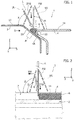
- heating of the sheet 4 (and of the weld material FW) at the second joining interface is obtained by means of a laser beam L ( Figures 1-3 ) with axis ⁇ L concentrated in the area 10.
- welding of the sheets 2, 4 to form the joint 1 is carried out by providing a shield-gas curtain SG around the area where heating takes place (the laser beam L and the shield-gas curtain SG are mobile in the welding direction YW together with the welding head, Figure 2 ).
- the joint exemplified in Figure 1 comprises, preferably adjacent to the groove 7, at least one planar surface.
- the planar surface is parallel to the plane XY.
- the planar surface is provided by one or other of the sheets 2, 4, and in the embodiment illustrated here it is provided by both of them, for a total of two planar surfaces adjacent to the groove 7.
- the sheet 2 adjacent to the flat member 2A, the sheet 2 comprises a planar surface 12, which forms an angle with the flat member 2A, whereas the sheet 4 comprises a planar surface 14, which terminates where the bent-back portion 4A starts.
- the surfaces 12, 14 are parallel to one another and to the plane XY.
- the laser beam L impinges upon the joining interface 10 with a first angle ⁇ comprised between 0° and 90°, preferably between 5° and 75°.
- the angle ⁇ is measured in the plane XZ (which is orthogonal to the direction of development of the groove 7, as well as being the direction of movement of the welding head) and corresponds to an angle of inclination of the laser beam L with respect to the planar surface 12.
- a second angle ⁇ is moreover defined between the direction of supply ZFW of the weld material FW, here parallel to the axis Z, and the planar surface 14 or 12, and is comprised between 0° and 90°.
- the angle ⁇ is measured in the plane XZ (which is orthogonal to the direction of development of the groove 7, as well as being the direction of movement of the welding head) and corresponds to an angle of inclination of the laser beam L with respect to the planar surface 12.
- the angle ⁇ is equal to the angle ⁇ ; i.e., the weld material FW is supplied in a direction parallel to the laser beam L.
- a third angle ⁇ is moreover defined measured between the direction of supply ZFW of the weld material FW and the direction of development (Y) of the groove 7, where the angle ⁇ is measured in a plane YZ parallel to the direction of development of the groove 7 and is comprised between 0° and 90°, preferably between 25° and 90°.
- the angle ⁇ is measured in the plane YZ and corresponds to an angle of inclination of the direction of supply ZFW with respect to the planar surface 14 (or 12).
- the perspective view of Figure 3 illustrates the development of the three angles ⁇ , ⁇ , ⁇ in space with respect to the joint 1.
- the weld bead 6 may be obtained in a continuous way, i.e., as a bead of molten weld material FW to form the weld bead 6 without any discontinuity (this involving the presence of joining interfaces 8, 10, which are also continuous in the direction of development Y of the groove 7), or else in a discontinuous way, i.e., with multiple stretches of molten weld material FW to form the weld bead 6 alternating with stretches where the joint is absent (in this case also the interfaces 8, 10 are discontinuous).
- a joint obtained by the welding method described above exhibits exceptional static mechanical properties and fatigue mechanical properties, and is likewise immune from phenomena of embrittlement thanks to the absence, or minimal presence, of inter-metal compounds at the interface between the two sheets, however dissimilar the materials constituting the latter may be.
Priority Applications (2)
| Application Number | Priority Date | Filing Date | Title |
|---|---|---|---|
| EP19155751.1A EP3693124A1 (fr) | 2019-02-06 | 2019-02-06 | Procédé permettant de fournir un joint soudé entre des matériaux dissemblables |
| US16/778,189 US11794265B2 (en) | 2019-02-06 | 2020-01-31 | Method for providing a welded joint between dissimilar materials |
Applications Claiming Priority (1)
| Application Number | Priority Date | Filing Date | Title |
|---|---|---|---|
| EP19155751.1A EP3693124A1 (fr) | 2019-02-06 | 2019-02-06 | Procédé permettant de fournir un joint soudé entre des matériaux dissemblables |
Publications (1)
| Publication Number | Publication Date |
|---|---|
| EP3693124A1 true EP3693124A1 (fr) | 2020-08-12 |
Family
ID=65635391
Family Applications (1)
| Application Number | Title | Priority Date | Filing Date |
|---|---|---|---|
| EP19155751.1A Pending EP3693124A1 (fr) | 2019-02-06 | 2019-02-06 | Procédé permettant de fournir un joint soudé entre des matériaux dissemblables |
Country Status (2)
| Country | Link |
|---|---|
| US (1) | US11794265B2 (fr) |
| EP (1) | EP3693124A1 (fr) |
Families Citing this family (2)
| Publication number | Priority date | Publication date | Assignee | Title |
|---|---|---|---|---|
| US20210046568A1 (en) * | 2019-08-13 | 2021-02-18 | Honda Motor Co., Ltd. | Bonding structure of dissimilar metal members and precursor thereof |
| CN114226943B (zh) * | 2022-01-06 | 2022-09-27 | 中国科学院上海光学精密机械研究所 | 一种焊接料片、输送系统、焊接装置及方法 |
Citations (6)
| Publication number | Priority date | Publication date | Assignee | Title |
|---|---|---|---|---|
| WO2002043913A1 (fr) * | 2000-12-01 | 2002-06-06 | Fronius Schweissmaschinen Produktion Gmbh & Co. Kg | Procede pour connecter des objets metalliques |
| EP1749616A1 (fr) * | 2005-08-05 | 2007-02-07 | Grillo-Werke AG | Procédé pour le soudage ou le brasage à l'arc ou à l'aide d'un faisceau à haute énergie de pièces en métaux identiques ou différents à l'aide d'un métal d'apport à base d'alliage d'étain; Fil à base d'alliage d'étain |
| US20120074111A1 (en) * | 2010-09-29 | 2012-03-29 | Kabushiki Kaisha Kobe Seiko Sho (Kobe Steel, Ltd.) | Flux-cored wire for welding different materials, method for laser welding of different materials and method for mig welding of different materials |
| DE102014217890A1 (de) * | 2014-09-08 | 2016-03-10 | Volkswagen Aktiengesellschaft | Verfahren zum Verbinden von metallischen Bauteilen unterschiedlicher Schmelztemperatur |
| US20160297020A1 (en) * | 2014-01-21 | 2016-10-13 | Kabushiki Kaisha Kobe Seiko Sho (Kobe Steel, Ltd.) | Joined body of dissimilar metals and method for producing joined body of dissimilar metals |
| DE102016006035A1 (de) * | 2016-05-18 | 2016-12-01 | Daimler Ag | Verfahren zum Verschweißen eines Stahlbauteils mit einem Aluminiumbauteil einer Anordnung |
Family Cites Families (2)
| Publication number | Priority date | Publication date | Assignee | Title |
|---|---|---|---|---|
| US7498543B2 (en) * | 2006-03-22 | 2009-03-03 | Gm Global Technology Operations, Inc. | Method for joining or repairing metal surface parts |
| EP2478992B1 (fr) * | 2008-04-21 | 2016-06-01 | Honda Motor Co., Ltd. | Procédé pour réunir des éléments métalliques |
-
2019
- 2019-02-06 EP EP19155751.1A patent/EP3693124A1/fr active Pending
-
2020
- 2020-01-31 US US16/778,189 patent/US11794265B2/en active Active
Patent Citations (6)
| Publication number | Priority date | Publication date | Assignee | Title |
|---|---|---|---|---|
| WO2002043913A1 (fr) * | 2000-12-01 | 2002-06-06 | Fronius Schweissmaschinen Produktion Gmbh & Co. Kg | Procede pour connecter des objets metalliques |
| EP1749616A1 (fr) * | 2005-08-05 | 2007-02-07 | Grillo-Werke AG | Procédé pour le soudage ou le brasage à l'arc ou à l'aide d'un faisceau à haute énergie de pièces en métaux identiques ou différents à l'aide d'un métal d'apport à base d'alliage d'étain; Fil à base d'alliage d'étain |
| US20120074111A1 (en) * | 2010-09-29 | 2012-03-29 | Kabushiki Kaisha Kobe Seiko Sho (Kobe Steel, Ltd.) | Flux-cored wire for welding different materials, method for laser welding of different materials and method for mig welding of different materials |
| US20160297020A1 (en) * | 2014-01-21 | 2016-10-13 | Kabushiki Kaisha Kobe Seiko Sho (Kobe Steel, Ltd.) | Joined body of dissimilar metals and method for producing joined body of dissimilar metals |
| DE102014217890A1 (de) * | 2014-09-08 | 2016-03-10 | Volkswagen Aktiengesellschaft | Verfahren zum Verbinden von metallischen Bauteilen unterschiedlicher Schmelztemperatur |
| DE102016006035A1 (de) * | 2016-05-18 | 2016-12-01 | Daimler Ag | Verfahren zum Verschweißen eines Stahlbauteils mit einem Aluminiumbauteil einer Anordnung |
Also Published As
| Publication number | Publication date |
|---|---|
| US20200246896A1 (en) | 2020-08-06 |
| US11794265B2 (en) | 2023-10-24 |
Similar Documents
| Publication | Publication Date | Title |
|---|---|---|
| JP7224871B2 (ja) | 異なる金属部分を融接するためのuam遷移 | |
| CA2509322C (fr) | Joint soude entre materiaux de nature differente forme par l'assemblage de materiau de type fer et de materiau de type aluminium, et methode d'assemblage par soudure | |
| Kah et al. | Trends in joining dissimilar metals by welding | |
| AU2006278029B2 (en) | Method for arc or beam brazing/welding of workspieces of identical or different metals or metal alloys with additional materials of Sn base alloys; Sn base alloy wire | |
| US20170291247A1 (en) | Al-steel weld joint | |
| US6905060B2 (en) | Method and sealant for weld joints | |
| Liu et al. | Joining of advanced high-strength steel to AA 6061 alloy by using Fe/Al structural transition joint | |
| US11794265B2 (en) | Method for providing a welded joint between dissimilar materials | |
| Ünel et al. | Properties and optimization of dissimilar aluminum steel CMT welds | |
| JP5466632B2 (ja) | 異材接合方法 | |
| CN114340833B (zh) | 异种材料接合结构体的制造方法和异种材料接合结构体 | |
| Silvayeh et al. | Mechanical properties and fracture modes of thin butt-joined aluminum-steel blanks for automotive applications | |
| EP3587614B1 (fr) | Procédé de brasage au laser et procédé de production d'un élément d'assemblage à recouvrement | |
| JP2006224146A (ja) | 異材接合方法 | |
| JP4438691B2 (ja) | 鉄系材料とアルミニウム系材料とを接合した異材接合継手および溶接接合方法 | |
| US20100001044A1 (en) | Full penetration weld joint | |
| JP2006312192A (ja) | 異種金属製品の接合方法 | |
| JP2008036704A (ja) | アルミ製品と鋼材製品との接合用継ぎ手及びそれを用いた接合方法 | |
| KR102061470B1 (ko) | Mig 브레이징 방법, 겹치기 이음 부재의 제조방법, 및 겹치기 이음 부재 | |
| Smith et al. | Friction stir welding in the automotive industry | |
| JP4256892B2 (ja) | 異材接合方法 | |
| US20220397141A1 (en) | Hybrid butt-lap joint, and method of production | |
| JP2000176644A (ja) | Al系めっき鋼板のアーク溶接方法 | |
| JP7120970B2 (ja) | 異種金属接合体の製造方法及び異種金属接合体 | |
| Xu et al. | Fracture Mode Variation Mechanism of Al/Steel Dissimilar Overlap Joint Made Using Variable Polarity Cold Metal Transfer-Based Arc Brazing |
Legal Events
| Date | Code | Title | Description |
|---|---|---|---|
| PUAI | Public reference made under article 153(3) epc to a published international application that has entered the european phase |
Free format text: ORIGINAL CODE: 0009012 |
|
| STAA | Information on the status of an ep patent application or granted ep patent |
Free format text: STATUS: THE APPLICATION HAS BEEN PUBLISHED |
|
| AK | Designated contracting states |
Kind code of ref document: A1 Designated state(s): AL AT BE BG CH CY CZ DE DK EE ES FI FR GB GR HR HU IE IS IT LI LT LU LV MC MK MT NL NO PL PT RO RS SE SI SK SM TR |
|
| AX | Request for extension of the european patent |
Extension state: BA ME |
|
| STAA | Information on the status of an ep patent application or granted ep patent |
Free format text: STATUS: REQUEST FOR EXAMINATION WAS MADE |
|
| 17P | Request for examination filed |
Effective date: 20210211 |
|
| RBV | Designated contracting states (corrected) |
Designated state(s): AL AT BE BG CH CY CZ DE DK EE ES FI FR GB GR HR HU IE IS IT LI LT LU LV MC MK MT NL NO PL PT RO RS SE SI SK SM TR |
|
| STAA | Information on the status of an ep patent application or granted ep patent |
Free format text: STATUS: EXAMINATION IS IN PROGRESS |
|
| 17Q | First examination report despatched |
Effective date: 20230503 |