EP3691566B1 - Verfahren zur herstellung einer geführten aufbissschiene - Google Patents
Verfahren zur herstellung einer geführten aufbissschiene Download PDFInfo
- Publication number
- EP3691566B1 EP3691566B1 EP18786242.0A EP18786242A EP3691566B1 EP 3691566 B1 EP3691566 B1 EP 3691566B1 EP 18786242 A EP18786242 A EP 18786242A EP 3691566 B1 EP3691566 B1 EP 3691566B1
- Authority
- EP
- European Patent Office
- Prior art keywords
- jaw
- model
- guide
- guided
- bite guard
- Prior art date
- Legal status (The legal status is an assumption and is not a legal conclusion. Google has not performed a legal analysis and makes no representation as to the accuracy of the status listed.)
- Active
Links
Images
Classifications
-
- A—HUMAN NECESSITIES
- A61—MEDICAL OR VETERINARY SCIENCE; HYGIENE
- A61C—DENTISTRY; APPARATUS OR METHODS FOR ORAL OR DENTAL HYGIENE
- A61C5/00—Filling or capping teeth
- A61C5/007—Dental splints; teeth or jaw immobilisation devices; stabilizing retainers bonded to teeth after orthodontic treatments
-
- A—HUMAN NECESSITIES
- A61—MEDICAL OR VETERINARY SCIENCE; HYGIENE
- A61C—DENTISTRY; APPARATUS OR METHODS FOR ORAL OR DENTAL HYGIENE
- A61C7/00—Orthodontics, i.e. obtaining or maintaining the desired position of teeth, e.g. by straightening, evening, regulating, separating, or by correcting malocclusions
- A61C7/002—Orthodontic computer assisted systems
-
- A—HUMAN NECESSITIES
- A61—MEDICAL OR VETERINARY SCIENCE; HYGIENE
- A61C—DENTISTRY; APPARATUS OR METHODS FOR ORAL OR DENTAL HYGIENE
- A61C11/00—Dental articulators, i.e. for simulating movement of the temporo-mandibular joints; Articulation forms or mouldings
-
- A—HUMAN NECESSITIES
- A61—MEDICAL OR VETERINARY SCIENCE; HYGIENE
- A61C—DENTISTRY; APPARATUS OR METHODS FOR ORAL OR DENTAL HYGIENE
- A61C11/00—Dental articulators, i.e. for simulating movement of the temporo-mandibular joints; Articulation forms or mouldings
- A61C11/02—Dental articulators, i.e. for simulating movement of the temporo-mandibular joints; Articulation forms or mouldings characterised by the arrangement, location or type of the hinge means ; Articulators with pivots
-
- A—HUMAN NECESSITIES
- A61—MEDICAL OR VETERINARY SCIENCE; HYGIENE
- A61C—DENTISTRY; APPARATUS OR METHODS FOR ORAL OR DENTAL HYGIENE
- A61C13/00—Dental prostheses; Making same
- A61C13/34—Making or working of models, e.g. preliminary castings, trial dentures; Dowel pins [4]
-
- A—HUMAN NECESSITIES
- A61—MEDICAL OR VETERINARY SCIENCE; HYGIENE
- A61C—DENTISTRY; APPARATUS OR METHODS FOR ORAL OR DENTAL HYGIENE
- A61C19/00—Dental auxiliary appliances
- A61C19/04—Measuring instruments specially adapted for dentistry
- A61C19/05—Measuring instruments specially adapted for dentistry for determining occlusion
-
- A—HUMAN NECESSITIES
- A61—MEDICAL OR VETERINARY SCIENCE; HYGIENE
- A61C—DENTISTRY; APPARATUS OR METHODS FOR ORAL OR DENTAL HYGIENE
- A61C7/00—Orthodontics, i.e. obtaining or maintaining the desired position of teeth, e.g. by straightening, evening, regulating, separating, or by correcting malocclusions
- A61C7/08—Mouthpiece-type retainers or positioners, e.g. for both the lower and upper arch
-
- A—HUMAN NECESSITIES
- A61—MEDICAL OR VETERINARY SCIENCE; HYGIENE
- A61C—DENTISTRY; APPARATUS OR METHODS FOR ORAL OR DENTAL HYGIENE
- A61C7/00—Orthodontics, i.e. obtaining or maintaining the desired position of teeth, e.g. by straightening, evening, regulating, separating, or by correcting malocclusions
- A61C7/36—Devices acting between upper and lower teeth
-
- A—HUMAN NECESSITIES
- A61—MEDICAL OR VETERINARY SCIENCE; HYGIENE
- A61F—FILTERS IMPLANTABLE INTO BLOOD VESSELS; PROSTHESES; DEVICES PROVIDING PATENCY TO, OR PREVENTING COLLAPSING OF, TUBULAR STRUCTURES OF THE BODY, e.g. STENTS; ORTHOPAEDIC, NURSING OR CONTRACEPTIVE DEVICES; FOMENTATION; TREATMENT OR PROTECTION OF EYES OR EARS; BANDAGES, DRESSINGS OR ABSORBENT PADS; FIRST-AID KITS
- A61F5/00—Orthopaedic methods or devices for non-surgical treatment of bones or joints; Nursing devices ; Anti-rape devices
- A61F5/56—Devices for preventing snoring
- A61F5/566—Intra-oral devices
-
- A—HUMAN NECESSITIES
- A61—MEDICAL OR VETERINARY SCIENCE; HYGIENE
- A61C—DENTISTRY; APPARATUS OR METHODS FOR ORAL OR DENTAL HYGIENE
- A61C13/00—Dental prostheses; Making same
- A61C13/0003—Making bridge-work, inlays, implants or the like
- A61C13/0006—Production methods
- A61C13/0013—Production methods using stereolithographic techniques
-
- A—HUMAN NECESSITIES
- A61—MEDICAL OR VETERINARY SCIENCE; HYGIENE
- A61F—FILTERS IMPLANTABLE INTO BLOOD VESSELS; PROSTHESES; DEVICES PROVIDING PATENCY TO, OR PREVENTING COLLAPSING OF, TUBULAR STRUCTURES OF THE BODY, e.g. STENTS; ORTHOPAEDIC, NURSING OR CONTRACEPTIVE DEVICES; FOMENTATION; TREATMENT OR PROTECTION OF EYES OR EARS; BANDAGES, DRESSINGS OR ABSORBENT PADS; FIRST-AID KITS
- A61F5/00—Orthopaedic methods or devices for non-surgical treatment of bones or joints; Nursing devices ; Anti-rape devices
- A61F5/56—Devices for preventing snoring
- A61F2005/563—Anti-bruxisme
Definitions
- the invention relates to a method for producing a guided bite splint for a supporting jaw, comprising at least one guide for an opposing jaw.
- Manufacturing methods for a guided bite splint are known from the prior art, in which a guided bite splint is clamped in an articulator and is gradually adjusted.
- the guideways are produced mechanically step by step by an articulation movement in the articulator, in that the material is removed step by step manually.
- DE 20 2010 006 250 U1 discloses a device for producing a guide splint for correcting the condyle position of a temporomandibular joint, the device having a variable-position platform on which a lower jaw model is arranged and its position relative to the upper jaw model is changed by means of a control device.
- DE 10 2013 112 032 A1 discloses a method for constructing a bite splint, with 3D data of the two jaws being recorded and the position of the jaws and the temporomandibular joints of the patient being recorded relative to one another, with an occlusion being simulated, with dental interference contacts of a craniomandibular system being identified and a bite splint under Using the captured 3D data and the simulation of the data obtained is constructed so that the identified interference contacts are eliminated become. To avoid pain, a series of several bite splints is designed to interactively approximate the physiological position of the temporomandibular joints location.
- US 2015/0238280 A1 discloses an apparatus and method for positioning the jaws for jaw correction, providing a treatment plan, wherein a virtual model of a dental appliance includes a first shell and a second shell configured to reposition the patient's two jaws.
- a first element may be attached to the upper shell and a second element may be attached to the lower shell, the two elements coming into contact with one another to bring about a desired displacement of the two jaws.
- EP 1516604 A1 discloses an intraoral therapy device, preferably a Schnuß therapy device, with an upper jaw splint and a lower jaw splint, the two splints being articulated to one another with a fixed rod.
- a disadvantage of the known methods is that the guides of a guided bite splint are added later by manual post-processing.
- the object of the present invention is therefore to provide a method for producing a guided bite splint that allows precise and time-saving production of a guided bite splint, with manual manufacturing errors, in particular of the guides of the bite splint, being to be avoided.
- the invention relates to a method for producing a guided bite splint for a supporting jaw, comprising at least one guide for an opposing jaw.
- a 3D model of an upper jaw and/or a 3D model of a lower jaw are already present, with the 3D models of the upper jaw and the lower jaw being arranged in an occlusal position relative to one another.
- a 3D model of the bite splint is then constructed using the 3D model of the upper jaw and/or the 3D model of the lower jaw, the at least one guide for the opposite jaw being automatically constructed with computer support on the 3D model of the bite splint.
- the guided bite splint is designed on the upper jaw as a supporting jaw and thus the lower jaw as the opposing jaw, or on the lower jaw as a supporting jaw and thus the upper jaw as the opposing jaw.
- a guided bite splint is used in the dental and orthodontic treatment of teeth grinding, bruxism and craniomandibular dysfunction, but also as a mouth guard.
- a guided bite splint can be a Michigan splint, for example, which is used to prevent muscle pain and joint pain as well as an unsafe final bite position.
- the Michigan splint acts primarily as a relaxation splint.
- the guidance of the lower jaw on the bite splint is mostly carried out in the canine area.
- the guided bite splint can also be a DROS bite splint, which is used in particular for mandibular stabilization.
- the guided bite splint thus serves as a relaxation splint to prevent occlusal malfunctions and to relax the masticatory muscles (reduction of muscle tone).
- the guided bite splint is also designed to protect against the destruction of hard tooth tissue caused by teeth grinding.
- a guided bite splint can be used to treat different malocclusions, such as a malocclusion with a recessed mandible or a malocclusion with a protruding mandible.
- the jaw abnormalities can be either congenital or acquired.
- the extent of the malocclusion only becomes clear when the jaw is closed and is shown, for example, by an open bite or by the upper teeth biting behind the lower teeth instead of the other way around.
- the position of the jaws in relation to each other and to the facial skeleton has a decisive influence on the facial profile. Depending on whether the overdevelopment or underdevelopment is localized in the upper and/or lower jaw, different facial profiles result parallel to the malocclusion.
- the guide of the bite splint is usually arranged in the front tooth area and/or in the canine tooth area and can have a certain angle of inclination relative to an insertion axis of the bite splint of between 20 and 40 degrees, usually in the lateral direction and/or protrusal direction of a jaw movement.
- the 3D model of the upper jaw and/or the lower jaw is already available for carrying out the method and was measured using an intraoral 3D camera, for example.
- the 3D models of the two jaws are arranged in the occlusal position relative to each other and in a virtual articulator model integrated.
- a lateral 3D image of the patient's two jaws in the final bite position can be used to arrange the two 3D models relative to one another.
- the at least one guide for the opposite jaw is designed automatically with the aid of a computer, with the guide of the bite splint exerting a force in a desired direction on the opposite jaw in the final bite position in order to correct the malocclusion.
- the lower jaw In the case of a protruding lower jaw, the lower jaw should be shifted in a distal direction towards the end of the dental arch in order to correct the malocclusion. With a receding mandible, the mandible should be shifted in a mesial direction towards the middle of the dental arch.
- An advantage of the present method is that the guided bite splint is designed virtually with computer support and the guided bite splint can be produced fully automatically using a CAD/CAM process or a 3D printer based on the constructed 3D model of the guided bite splint.
- a further advantage of the present method is that the at least one guide of the guided bite splint can be positioned exactly and adjusted precisely to the opposite jaw. The time-consuming, step-by-step removal of the material for producing the guides is saved in comparison to the known production methods.
- the 3D models of the upper jaw and the lower jaw can be integrated in a virtual articulator model that simulates an articulation movement of the lower jaw relative to the upper jaw.
- an articulator is simulated that imitates the movement of the temporomandibular joint.
- the movement of the jaws relative to one another is simulated, with the jaw joint being able to perform both rotational movements (opening and closing movements around the joint axis) and sliding movements (advancing movements).
- the temporomandibular joints consist of a cartilage-covered joint head, a joint cavity also covered with cartilage and the fibro-cartilaginous intermediate joint disc.
- the temporomandibular joint also consists of soft-tissue structures such as the ligaments, vessels and nerves. When the mouth is opened, the joint head slides forward and down together with the disk, which is normally firmly connected to the joint head.
- the temporomandibular joints and chewing muscles are active in all movements performed by the lower jaw. These movements should be imitated using the virtual articulator model.
- the relative positions of the two jaws to one another can be measured for different opening angles and correspondingly transferred to the virtual articulator model.
- the guided bite splint is then computer-aided constructed using the two 3D models of the jaws and taking into account the simulated movements of the temporomandibular joints in the virtual articulator model.
- the movements of the two jaws relative to one another can also be calculated or simulated using so-called heuristics, for example a translatory movement of the two 3D models of the jaws relative to one another.
- the expansion of the guided bite splint on the upper jaw or on the lower jaw as Support pine computer-aided automatically or set by a user.
- the extent can be determined by the user using a virtual tool by drawing the limit of the guided bite splint on the 3D model of the supporting jaw.
- the extent of the bite splint can be determined automatically with the aid of a computer by accessing a database of different 3D models of supporting jaws and selecting a suitable 3D model of a supporting jaw for which the extent of the bite splint has already been defined.
- a minimum thickness of the guided bite splint can be set automatically with the aid of a computer or by a user.
- the minimum thickness of the bite splint can be determined.
- the user can manually enter the value for the minimum thickness.
- the minimum thickness can be determined automatically with the aid of a computer by comparing the measured 3D model of the supporting jaw with the database of different supporting jaws for which the minimum thicknesses have already been defined.
- the guided bite splint must have the specified minimum thickness everywhere along an axis of insertion of the bite splint.
- the insertion axis is defined by an insertion direction when placing the bite splint on the supporting jaw.
- the specified minimum thickness can be undershot towards the edge of the bite splint.
- a defined distance of an occlusion opening in a desired occlusal position guided bite splint computer-aided automatically or set by a user.
- the distance can be entered by a user, for example, or it can be automatically compared with known occlusion openings using a database of different supporting jaws and opposing jaws.
- the distance between the occlusion opening can be defined, for example, by the distance between the corresponding occlusion contacts of the supporting jaw and the opposing jaw.
- the 3D model of the guided bite splint is automatically calculated with the help of a computer, whereby the conditions must be met that the guided bite splint covers a defined contact area on the supporting jaw, that at least one local cusp tip is defined as a contact point for at least one tooth of the opposing jaw.
- the 3D model of the guided bite splint is automatically calculated with the aid of the computer, whereby the conditions are met.
- the defined contact area can be determined beforehand manually by a user or automatically with the aid of a computer by comparing different contact jaws with a database.
- the defined support point for the individual teeth ensures a stable mechanical support of the bite splint on the support jaw.
- At least one guide point of the guide to be constituted on the opposing jaw can be defined automatically with the aid of a computer or manually by a user.
- the guide point is defined manually by the user using a virtual tool or automatically with the aid of a computer by comparing different supporting jaws and opposing jaws with fixed guide points in a database.
- At least one movement profile can advantageously be defined for each guide point.
- a movement profile is thus defined for each guide point by the user, for example using a virtual tool.
- the movement profile is defined as a function of the jaw opening as a function of a jaw movement distance.
- the movement profile thus lays out a desired course of movement of the opposite jaw with a reduction in the jaw opening up to a closed occlusal position in which the opposite jaw bites onto the bite splint.
- For the desired course of movement for example, a force is exerted on the lower jaw in a distal direction when the lower jaw protrudes, and a force is exerted in a mesial direction when the lower jaw is receding.
- the movement profile goes through a defined plane that goes through the guide point and runs, for example, along a direction of the insertion axis.
- Several movement profiles can also be defined in different planes for a guide point.
- the surface shape of the guide can be calculated automatically with the aid of a computer as a function of the at least one movement profile.
- the surface shape of the guide is automatically calculated with the aid of a computer as a function of at least one defined movement profile.
- the surface of the 3D model of the guided bite splint in the Areas of the guides are adjusted or guided accordingly, with a gap between the defined movement profiles can be interpolated so that a smooth transition of the surface shape of the guide is created.
- the surface shape of the guide is calculated so that the designed guide leads to the desired course of movement of the opposing jaw relative to the bite splint and relative to the supporting jaw according to the defined movement profiles.
- At least two movement profiles can be defined in two different planes for each guide point, with the surface shape of the guide being interpolated between the two planes of the two movement profiles in such a way that a smooth transition is produced.
- the interpolation between the movement profiles results in a smooth transition of the surface shape of the guide, with the desired course of movement of the opposite jaw relative to the supporting jaw being achieved by the constructed guide.
- a first plane of a first movement profile can be arranged, for example, in a lateral (sideways) direction of movement and a second plane of a second movement profile can be arranged, for example, in a protrusional (back and forth) direction of movement.
- the surface of the virtual 3D model of the guided bite splint can be reduced to such an extent that no surface point of the 3D model of the opposing jaw is virtually penetrated, as long as the opposing jaw is within a defined range of motion along the at least one guide within the virtual articulator model is moved.
- the guided bite splint can be manufactured fully automatically using a subtractive manufacturing method, such as a CAM manufacturing machine, or using an additive manufacturing method, such as a 3D printer, based on the designed 3D model of the bite splint.
- a subtractive manufacturing method such as a CAM manufacturing machine
- an additive manufacturing method such as a 3D printer
- the guided bite splint is manufactured fully automatically according to the designed 3D model.
- a blank is clamped into the CAM production machine and processed using milling tools and/or grinding tools until the guided bite splint is produced according to the designed 3D model.
- the designed bite splint is printed out.
- the 3D printer can, for example, be based on an SLS (Selective Laser Sintering) process, which enables the printing of three-dimensional objects without binders or additional assembly steps.
- SLS Selective Laser Sintering
- the existing 3D model of the bite splint is divided into many horizontal levels using special slicing software and forwarded to the 3D printer as control commands.
- the 3D printer then prints out the object layer by layer, with individual powder particles in are fused together in a bed of powder by the high temperature of a laser. The object is then lowered and a new layer of powder is applied. The process is repeated until the entire guided bite splint is completely printed.
- the 3D printer can also be based on a stereolithography process, using a laser that polymerizes a mass composed of photosensitive resin and material particles.
- the material of the guided bite splint can be a plastic with a suitable hardness, for example. The hardness and elasticity of the plastic are selected in such a way that the opposing jaw can be precisely guided along the designed guides.
- the bite splint can also be made from different plastics.
- a further object of the invention is the guided bite splint produced using the above-mentioned method, the at least one guide for the opposing jaw being designed automatically with the aid of a computer.
- the guide for the opposing jaw can be constructed using the at least one movement profile at at least one guide point.
- the guide is constructed using the defined movement profile, so that the guide leads to the desired course of movement of the opposing jaw.
- the guided bite splint can be fully automated based on the constructed 3D model of the bite splint be made by a subtractive manufacturing process, such as a CAM manufacturing machine, or by an additive manufacturing process, such as a 3D printer.
- the guided bite splint is produced fully automatically and thus in a time-saving manner, with possible manufacturing errors from manual production of the guides being avoided.
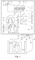
- the 1 shows a sketch to clarify the method for producing a guided bite splint 1 for a supporting jaw 2, in the present case for the upper jaw, comprising at least one guide 3.
- the bite splint 1 has several guides 3 with the opposing jaw 4, in the present case for the lower jaw, up.
- a 3D model 5 of the upper jaw and a 3D model 6 of the lower jaw already exist and were measured on the patient using an intraoral 3D camera.
- the 3D model 5 of the upper jaw and the 3D model 6 of the lower jaw are arranged in an occlusal position 7 relative to one another and are integrated in a virtual articulator model 8 .
- the articulator model 8 simulates an articulation movement of the jaw joint 9, which is shown as a cross for clarity, and thus of the lower jaw 6 relative to the upper jaw 5.
- the articulation movement of the temporomandibular joint 9 can be composed of a rotational movement 10, a feed movement 11 in the horizontal direction, a movement 12 in the vertical direction relative to the 3D model 5 of the upper jaw and a sideways movement, not shown, in a direction of the axis of rotation of the temporomandibular joint 9.
- a 3D model 13 of the guided bite splint 13 is then constructed using the 3D model 5 of the upper jaw 2 and the 3D model 6 of the lower jaw 4, with the simulated movement of the lower jaw 4 relative to the upper jaw 2 from the articulator model 8 being used.
- a first guide point 14, a second guide point 15 and a third guide point 16 are then manually set on the 3D model 13 of the bite splint 1 by a user or automatically with the aid of a computer.
- the guide points 14, 15 and 16 on the 3D model 13 of the bite splint are fixed in relation to their positions on the opposite jaw 4.
- the extent of the 3D model 13 of the bite splint 1 relative to the 3D model 5 of the supporting jaw 2 is determined manually by the user or automatically with the aid of a computer in such a way that at least a defined contact area of the supporting jaw 2 is covered and an opening in the jaw has a defined value .
- the 3D model 13 of the bite splint 1 is constructed in such a way that a local cusp tip is defined as a support point 18 for each tooth 17 of the opposing jaw 4 .
- the support points 18 are shown as crosses on the counter-teeth 17 .
- a first movement profile 19 is defined in a first plane, a second movement profile 20 in a second plane and a third profile 21 in a third plane.
- a first diagram 24 shows an example of a first function 25 of the first movement profile 19 as a function of an opening 26 in the opposing jaw 4, namely a distance between the jaws, depending on a distance 27 of the respective sliding contact point of the opposing jaw in the guide relative to the respective guide point applied in the plane of the respective movement profile.
- the first function 25 for the first movement profile 19 has a linear progression.
- a second function 28 of the second movement profile 20 has an exponential profile.
- a third function 29 of the third movement profile 21 has an S-shaped profile.
- the surface shape of the first guide 3 is automatically calculated with the aid of a computer.
- the second guide 30 is calculated as a function of the five movement profiles 22 of the second guide point 15 .
- the third guide 31 is calculated as a function of the movement profiles 23 of the third guide point 16 .
- the surface shape of the guide 3, 30, 31 is interpolated in an intermediate area 32 between adjacent movement profiles, so that there is a smooth transition in the surface shape of the guide.
- the guided bite splint is constructed virtually by means of a computer 33, a display device 34, such as a monitor, and operating elements, such as a keyboard 35 and a mouse 36, being connected to the computer 33.
- the construction of the 3D model 13 of the bite splint 1 can be computer-assisted, automatically and/or manually by a user using a virtual tool 37, such as a cursor.
- a virtual tool 37 such as a cursor.
- the design data is passed to a CAM manufacturing machine 38 .
- the guided bite splint 1 to be produced is then ground out with the guides 3 from a blank 39, which can be made from a special plastic.
- the guided bite splint 1 can also be produced using a 3D printer.
Landscapes
- Health & Medical Sciences (AREA)
- Life Sciences & Earth Sciences (AREA)
- Veterinary Medicine (AREA)
- Public Health (AREA)
- General Health & Medical Sciences (AREA)
- Animal Behavior & Ethology (AREA)
- Epidemiology (AREA)
- Dentistry (AREA)
- Oral & Maxillofacial Surgery (AREA)
- Engineering & Computer Science (AREA)
- General Engineering & Computer Science (AREA)
- Biomedical Technology (AREA)
- Nursing (AREA)
- Pulmonology (AREA)
- Orthopedic Medicine & Surgery (AREA)
- Otolaryngology (AREA)
- Heart & Thoracic Surgery (AREA)
- Vascular Medicine (AREA)
- Biophysics (AREA)
- Dental Tools And Instruments Or Auxiliary Dental Instruments (AREA)
- Measurement Of The Respiration, Hearing Ability, Form, And Blood Characteristics Of Living Organisms (AREA)
- Dental Prosthetics (AREA)
Applications Claiming Priority (2)
| Application Number | Priority Date | Filing Date | Title |
|---|---|---|---|
| DE102017217558.3A DE102017217558A1 (de) | 2017-10-02 | 2017-10-02 | Verfahren zur Herstellung einer geführten Aufbissschiene und eine geführte Aufbissschiene |
| PCT/EP2018/076780 WO2019068703A1 (de) | 2017-10-02 | 2018-10-02 | Verfahren zur herstellung einer geführten aufbissschiene und eine geführte aufbissschiene |
Publications (2)
| Publication Number | Publication Date |
|---|---|
| EP3691566A1 EP3691566A1 (de) | 2020-08-12 |
| EP3691566B1 true EP3691566B1 (de) | 2023-02-22 |
Family
ID=63857880
Family Applications (1)
| Application Number | Title | Priority Date | Filing Date |
|---|---|---|---|
| EP18786242.0A Active EP3691566B1 (de) | 2017-10-02 | 2018-10-02 | Verfahren zur herstellung einer geführten aufbissschiene |
Country Status (7)
| Country | Link |
|---|---|
| US (1) | US11583367B2 (enExample) |
| EP (1) | EP3691566B1 (enExample) |
| JP (2) | JP2020535934A (enExample) |
| KR (1) | KR102580303B1 (enExample) |
| CN (1) | CN111182853B (enExample) |
| DE (1) | DE102017217558A1 (enExample) |
| WO (1) | WO2019068703A1 (enExample) |
Families Citing this family (11)
| Publication number | Priority date | Publication date | Assignee | Title |
|---|---|---|---|---|
| AU2019262095B2 (en) * | 2018-05-02 | 2024-05-16 | Open Airway Dental Solutions Ltd | Breathing assistance oral apparatus |
| DE102019104382B3 (de) * | 2019-02-21 | 2020-06-18 | Image Instruments Gmbh | Okklusionskontrollsystem und Verfahren zur Okklusionskontrolle |
| US20200375790A1 (en) * | 2019-05-31 | 2020-12-03 | R. Joseph Magness | Dental appliance for treatment of bruxism and sleep apnea |
| DE102019118806A1 (de) | 2019-07-11 | 2021-01-14 | Peter Schweiger | Materialzusammensetzung u.a. für Aufbissschienen in der Dentaltechnik, Verfahren zu ihrer Herstellung und ihre Verwendung |
| EP4127600B1 (en) * | 2020-03-30 | 2025-09-03 | Dimension Ortho Inc. | Apparatus for anatomic three-dimensional scanning and automated three-dimensional cast and splint design |
| RU2735984C2 (ru) * | 2020-06-10 | 2020-11-11 | Арсен Овсепович Казарян | Способ построения и отображения компьютерных 3d-моделей височно-нижнечелюстных суставов |
| CN112022384B (zh) * | 2020-09-04 | 2022-12-06 | 上海交通大学医学院附属第九人民医院 | 基于cad/cam的数字化树脂板、制备方法及应用 |
| CN112168396B (zh) * | 2020-10-21 | 2021-08-10 | 成都登特牙科技术开发有限公司 | 咬合板、咬合板的数字化设计方法及3d打印生产方法 |
| KR102498809B1 (ko) * | 2020-10-23 | 2023-02-09 | 사회복지법인 삼성생명공익재단 | 치아교합시뮬레이션 방법 및 시스템 |
| RU2758752C1 (ru) * | 2021-02-11 | 2021-11-01 | Общество с ограниченной ответственностью "ДЕНТАЛЬНЫЙ ПРОЦЕССИНГОВЫЙ ЦЕНТР" | Способ и система автоматизированного моделирования ортотика |
| EP4555971A1 (en) * | 2022-07-13 | 2025-05-21 | Medit Corp. | Image processing method, electronic device and computer-readable storage medium |
Citations (6)
| Publication number | Priority date | Publication date | Assignee | Title |
|---|---|---|---|---|
| US20050022824A1 (en) * | 2003-07-25 | 2005-02-03 | Harry Ball | Occlusal splint |
| DE202004020196U1 (de) * | 2004-12-30 | 2005-05-04 | Weiss, Franz | Oberkiefer-Aufbißschiene |
| EP1516604B1 (de) * | 2003-09-16 | 2008-05-21 | Dr. Hinz Labor, Fachlaboratorium für Kieferorthopädie GmbH & Co. KG | Intraorales Therapiegerät |
| WO2011131243A1 (de) * | 2010-04-22 | 2011-10-27 | Elmar Frank | Rechnergestütztes verfahren zur herstellung von bissschienen |
| WO2012140021A2 (en) * | 2011-04-10 | 2012-10-18 | 3Shape A/S | Modeling and manufacturing orthodontic appliances |
| WO2017125799A1 (en) * | 2016-01-19 | 2017-07-27 | Lucera Investments SAGL | Occlusal splint |
Family Cites Families (25)
| Publication number | Priority date | Publication date | Assignee | Title |
|---|---|---|---|---|
| US6152731A (en) * | 1997-09-22 | 2000-11-28 | 3M Innovative Properties Company | Methods for use in dental articulation |
| CA2350849A1 (fr) * | 2001-06-15 | 2002-12-15 | Dentalmatic Technologies Inc. | Articulateur virtuel |
| US7458810B2 (en) * | 2002-09-20 | 2008-12-02 | Bergersen Earl O | Dental appliance having an altered vertical thickness between an upper shell and a lower shell with an integrated hinging mechanism to attach an upper shell and a lower shell and a system and a method for treating malocclusions |
| US7474932B2 (en) * | 2003-10-23 | 2009-01-06 | Technest Holdings, Inc. | Dental computer-aided design (CAD) methods and systems |
| US20090305185A1 (en) * | 2008-05-05 | 2009-12-10 | Lauren Mark D | Method Of Designing Custom Articulator Inserts Using Four-Dimensional Data |
| US7835811B2 (en) * | 2006-10-07 | 2010-11-16 | Voxelogix Corporation | Surgical guides and methods for positioning artificial teeth and dental implants |
| US9539062B2 (en) * | 2006-10-16 | 2017-01-10 | Natural Dental Implants, Ag | Methods of designing and manufacturing customized dental prosthesis for periodontal or osseointegration and related systems |
| JP5586590B2 (ja) * | 2008-06-02 | 2014-09-10 | デンツプライ インターナショナル インコーポレーテッド | 患者のデジタル画像を用いて特別仕様の歯科補綴装置を設計する方法 |
| CA2674656C (en) * | 2009-08-14 | 2010-10-12 | Douglas Awde | Removable bite plane appliance |
| DE202010006250U1 (de) | 2010-04-29 | 2010-09-09 | C. Hafner Gmbh + Co. Kg | Vorrichtung zur Herstellung einer Schiene oder Prothese zur Korrektur der Kondylenposition eines Kiefergelenks |
| DE102012005323B4 (de) * | 2012-03-19 | 2015-05-13 | Gernot Heine | Apparatur für kiefergelenksbezügliche Zahnstellungskorrekturen und Verfahren zur Herstellung der Apparatur |
| GB201216230D0 (en) * | 2012-09-12 | 2012-10-24 | Nobel Biocare Services Ag | An improved surgical template |
| GB201216214D0 (en) * | 2012-09-12 | 2012-10-24 | Nobel Biocare Services Ag | A digital splint |
| GB201216224D0 (en) * | 2012-09-12 | 2012-10-24 | Nobel Biocare Services Ag | An improved virtual splint |
| US11000348B2 (en) * | 2012-10-18 | 2021-05-11 | 3Shape A/S | Multiple bite configurations |
| KR101491041B1 (ko) * | 2012-11-30 | 2015-02-06 | 재단법인 아산사회복지재단 | 악 교정용 웨이퍼 제작 방법 |
| DE102012023565A1 (de) * | 2012-12-01 | 2014-06-05 | Dreve Prodimed Gmbh | Verfahren und Vorrichtung zur Herstellung von für dentale Zwecke bestimmten mundgetragenen Schienen |
| US9730768B2 (en) * | 2013-02-22 | 2017-08-15 | Kelly Lucas | CAD-CAM AGP splint—a method of automatically producing or reproducing a customized AGP (anterior guidance package) equipped splint for a patient with/without a severe malocclusion via one time dentist visit |
| WO2015003018A1 (en) * | 2013-07-01 | 2015-01-08 | Magness Joseph R | Dental appliance for treatment of bruxism |
| DE102013112032B4 (de) | 2013-10-31 | 2018-10-31 | Bernhard Egger | Verfahren zum Konstruieren einer Aufbissschiene |
| US10537406B2 (en) * | 2014-02-21 | 2020-01-21 | Align Technology, Inc. | Dental appliance with repositioning jaw elements |
| JP6262179B2 (ja) * | 2014-12-05 | 2018-01-17 | ディオ コーポレーションDio Corporation | デンタルインプラント施術のための手術ガイドおよび植立物の製造方法 |
| KR101676205B1 (ko) * | 2015-12-31 | 2016-11-15 | 이민정 | 투명교정기 제조방법 |
| IL264881B2 (en) * | 2016-08-19 | 2024-02-01 | The Methodist Hospital System | Systems and methods for computer-aided planning of orthogenetic analysis |
| RU2652014C1 (ru) * | 2017-09-20 | 2018-04-24 | Общество с ограниченной ответственностью "Авантис3Д" | Способ использования динамического виртуального артикулятора для имитационного моделирования окклюзии при выполнении проектирования стоматологических протезов для пациента и носитель информации |
-
2017
- 2017-10-02 DE DE102017217558.3A patent/DE102017217558A1/de not_active Withdrawn
-
2018
- 2018-10-02 US US16/648,099 patent/US11583367B2/en active Active
- 2018-10-02 JP JP2020539145A patent/JP2020535934A/ja active Pending
- 2018-10-02 WO PCT/EP2018/076780 patent/WO2019068703A1/de not_active Ceased
- 2018-10-02 CN CN201880064556.3A patent/CN111182853B/zh active Active
- 2018-10-02 EP EP18786242.0A patent/EP3691566B1/de active Active
- 2018-10-02 KR KR1020207007199A patent/KR102580303B1/ko active Active
-
2023
- 2023-12-07 JP JP2023206767A patent/JP2024023588A/ja active Pending
Patent Citations (6)
| Publication number | Priority date | Publication date | Assignee | Title |
|---|---|---|---|---|
| US20050022824A1 (en) * | 2003-07-25 | 2005-02-03 | Harry Ball | Occlusal splint |
| EP1516604B1 (de) * | 2003-09-16 | 2008-05-21 | Dr. Hinz Labor, Fachlaboratorium für Kieferorthopädie GmbH & Co. KG | Intraorales Therapiegerät |
| DE202004020196U1 (de) * | 2004-12-30 | 2005-05-04 | Weiss, Franz | Oberkiefer-Aufbißschiene |
| WO2011131243A1 (de) * | 2010-04-22 | 2011-10-27 | Elmar Frank | Rechnergestütztes verfahren zur herstellung von bissschienen |
| WO2012140021A2 (en) * | 2011-04-10 | 2012-10-18 | 3Shape A/S | Modeling and manufacturing orthodontic appliances |
| WO2017125799A1 (en) * | 2016-01-19 | 2017-07-27 | Lucera Investments SAGL | Occlusal splint |
Also Published As
| Publication number | Publication date |
|---|---|
| JP2024023588A (ja) | 2024-02-21 |
| KR20200066293A (ko) | 2020-06-09 |
| EP3691566A1 (de) | 2020-08-12 |
| WO2019068703A1 (de) | 2019-04-11 |
| CN111182853B (zh) | 2022-08-02 |
| JP2020535934A (ja) | 2020-12-10 |
| US20200275995A1 (en) | 2020-09-03 |
| US11583367B2 (en) | 2023-02-21 |
| DE102017217558A1 (de) | 2019-04-04 |
| CN111182853A (zh) | 2020-05-19 |
| KR102580303B1 (ko) | 2023-09-18 |
Similar Documents
| Publication | Publication Date | Title |
|---|---|---|
| EP3691566B1 (de) | Verfahren zur herstellung einer geführten aufbissschiene | |
| EP2062224B1 (de) | Verfahren zur herstellung von mindestens einem operationssplint, insbesondere für computerassistierte maxillofaziale operationen und umstellungsosteotomien | |
| DE60320498T2 (de) | Vorrichtung zur orthodonischen Korrektur | |
| EP3145437A1 (de) | Kieferorthopädische apparatur und verfahren zur herstellung einer kieferorthopädischen apparatur | |
| DE102010002206A1 (de) | Bracketsystem und Verfahren zur Planung und Herstellung eines Bracketsystems zur Korrektur von Zahnfehlstellungen | |
| WO2016071508A1 (de) | Verfahren zur herstellung einer vorgespannten zahn-repositionierungseinrichtung | |
| EP3743012B1 (de) | Verfahren zur herstellung einer dentalprothese | |
| DE102017113814B4 (de) | Verfahren zur Herstellung einer Dentalprothese mit definiertem Klebespalt | |
| EP3151776B1 (de) | Verfahren zur herstellung einer zahnmedizinischen bohrschablone | |
| EP2964132B1 (de) | Verfahren zur herstellung eines kieferorthopädischen setups | |
| EP3258889B1 (de) | Orthese und verfahren zur herstellung einer orthese | |
| EP1915104B1 (de) | Verfahren zum Ermitteln der Zentrikposition eines menschlichen Gebisses | |
| DE102009009916A1 (de) | Rechnergestütztes Verfahren zur Herstellung von Bissschienen | |
| WO2011131243A1 (de) | Rechnergestütztes verfahren zur herstellung von bissschienen | |
| DE3542177A1 (de) | Verfahren und vorrichtung zur gelenkbezueglichen rekonstruktion von zaehnen | |
| DE102011084111A1 (de) | Verfahren und Anordnung zur Festlegung der korrekten Position eines Unterkiefermodells bezüglich eines Oberkiefermodells | |
| DE102012018997B4 (de) | Verfahren zum Positionieren von mindestens einem Zahnbogenmodell in einem Artikulator, Computerprogramm sowie Artikulator | |
| DE102018101663B4 (de) | Verfahren zur Herstellung einer Dentalprothese | |
| DE102010018825B4 (de) | Vorrichtung und Verfahren zur Positionierung eines realen Unterkiefermodells und eines Oberkiefermodells zur Herstellung einer Schiene oder Prothese zur Korrektur der Kondylenposition eines Kiefergelenks | |
| WO2017178050A1 (de) | Medizinischer strahlenprotektor und seine herstellung | |
| DE102019106141A1 (de) | Biomechanische Vorrichtung für das Kiefergelenk | |
| AT396645B (de) | Vorrichtung zum übertragen von korrekturbewegungen auf einen gesichtsschädel | |
| DE102022128845A1 (de) | Verfahren für die kieferorthopädische Behandlungsplanung und zur Visualisierung von Behandlungsschritten | |
| DE102008006644B4 (de) | Vorrichtung und Verfahren zur Bestimmung einer ursprünglichen horizontalen Kauebene | |
| WO2012055404A2 (de) | Artikulator, gelenkteil für einen artikulator sowie verfahren zu dessen herstellung |
Legal Events
| Date | Code | Title | Description |
|---|---|---|---|
| STAA | Information on the status of an ep patent application or granted ep patent |
Free format text: STATUS: UNKNOWN |
|
| STAA | Information on the status of an ep patent application or granted ep patent |
Free format text: STATUS: THE INTERNATIONAL PUBLICATION HAS BEEN MADE |
|
| PUAI | Public reference made under article 153(3) epc to a published international application that has entered the european phase |
Free format text: ORIGINAL CODE: 0009012 |
|
| STAA | Information on the status of an ep patent application or granted ep patent |
Free format text: STATUS: REQUEST FOR EXAMINATION WAS MADE |
|
| 17P | Request for examination filed |
Effective date: 20200318 |
|
| AK | Designated contracting states |
Kind code of ref document: A1 Designated state(s): AL AT BE BG CH CY CZ DE DK EE ES FI FR GB GR HR HU IE IS IT LI LT LU LV MC MK MT NL NO PL PT RO RS SE SI SK SM TR |
|
| AX | Request for extension of the european patent |
Extension state: BA ME |
|
| STAA | Information on the status of an ep patent application or granted ep patent |
Free format text: STATUS: EXAMINATION IS IN PROGRESS |
|
| 17Q | First examination report despatched |
Effective date: 20201015 |
|
| DAV | Request for validation of the european patent (deleted) | ||
| DAX | Request for extension of the european patent (deleted) | ||
| GRAP | Despatch of communication of intention to grant a patent |
Free format text: ORIGINAL CODE: EPIDOSNIGR1 |
|
| STAA | Information on the status of an ep patent application or granted ep patent |
Free format text: STATUS: GRANT OF PATENT IS INTENDED |
|
| INTG | Intention to grant announced |
Effective date: 20220914 |
|
| GRAS | Grant fee paid |
Free format text: ORIGINAL CODE: EPIDOSNIGR3 |
|
| GRAA | (expected) grant |
Free format text: ORIGINAL CODE: 0009210 |
|
| STAA | Information on the status of an ep patent application or granted ep patent |
Free format text: STATUS: THE PATENT HAS BEEN GRANTED |
|
| AK | Designated contracting states |
Kind code of ref document: B1 Designated state(s): AL AT BE BG CH CY CZ DE DK EE ES FI FR GB GR HR HU IE IS IT LI LT LU LV MC MK MT NL NO PL PT RO RS SE SI SK SM TR |
|
| REG | Reference to a national code |
Ref country code: GB Ref legal event code: FG4D Free format text: NOT ENGLISH |
|
| REG | Reference to a national code |
Ref country code: CH Ref legal event code: EP |
|
| REG | Reference to a national code |
Ref country code: AT Ref legal event code: REF Ref document number: 1549031 Country of ref document: AT Kind code of ref document: T Effective date: 20230315 Ref country code: IE Ref legal event code: FG4D Free format text: LANGUAGE OF EP DOCUMENT: GERMAN |
|
| REG | Reference to a national code |
Ref country code: DE Ref legal event code: R096 Ref document number: 502018011655 Country of ref document: DE |
|
| REG | Reference to a national code |
Ref country code: LT Ref legal event code: MG9D |
|
| REG | Reference to a national code |
Ref country code: NL Ref legal event code: MP Effective date: 20230222 |
|
| PG25 | Lapsed in a contracting state [announced via postgrant information from national office to epo] |
Ref country code: RS Free format text: LAPSE BECAUSE OF FAILURE TO SUBMIT A TRANSLATION OF THE DESCRIPTION OR TO PAY THE FEE WITHIN THE PRESCRIBED TIME-LIMIT Effective date: 20230222 Ref country code: PT Free format text: LAPSE BECAUSE OF FAILURE TO SUBMIT A TRANSLATION OF THE DESCRIPTION OR TO PAY THE FEE WITHIN THE PRESCRIBED TIME-LIMIT Effective date: 20230622 Ref country code: NO Free format text: LAPSE BECAUSE OF FAILURE TO SUBMIT A TRANSLATION OF THE DESCRIPTION OR TO PAY THE FEE WITHIN THE PRESCRIBED TIME-LIMIT Effective date: 20230522 Ref country code: NL Free format text: LAPSE BECAUSE OF FAILURE TO SUBMIT A TRANSLATION OF THE DESCRIPTION OR TO PAY THE FEE WITHIN THE PRESCRIBED TIME-LIMIT Effective date: 20230222 Ref country code: LV Free format text: LAPSE BECAUSE OF FAILURE TO SUBMIT A TRANSLATION OF THE DESCRIPTION OR TO PAY THE FEE WITHIN THE PRESCRIBED TIME-LIMIT Effective date: 20230222 Ref country code: LT Free format text: LAPSE BECAUSE OF FAILURE TO SUBMIT A TRANSLATION OF THE DESCRIPTION OR TO PAY THE FEE WITHIN THE PRESCRIBED TIME-LIMIT Effective date: 20230222 Ref country code: HR Free format text: LAPSE BECAUSE OF FAILURE TO SUBMIT A TRANSLATION OF THE DESCRIPTION OR TO PAY THE FEE WITHIN THE PRESCRIBED TIME-LIMIT Effective date: 20230222 Ref country code: ES Free format text: LAPSE BECAUSE OF FAILURE TO SUBMIT A TRANSLATION OF THE DESCRIPTION OR TO PAY THE FEE WITHIN THE PRESCRIBED TIME-LIMIT Effective date: 20230222 |
|
| PG25 | Lapsed in a contracting state [announced via postgrant information from national office to epo] |
Ref country code: SE Free format text: LAPSE BECAUSE OF FAILURE TO SUBMIT A TRANSLATION OF THE DESCRIPTION OR TO PAY THE FEE WITHIN THE PRESCRIBED TIME-LIMIT Effective date: 20230222 Ref country code: PL Free format text: LAPSE BECAUSE OF FAILURE TO SUBMIT A TRANSLATION OF THE DESCRIPTION OR TO PAY THE FEE WITHIN THE PRESCRIBED TIME-LIMIT Effective date: 20230222 Ref country code: IS Free format text: LAPSE BECAUSE OF FAILURE TO SUBMIT A TRANSLATION OF THE DESCRIPTION OR TO PAY THE FEE WITHIN THE PRESCRIBED TIME-LIMIT Effective date: 20230622 Ref country code: GR Free format text: LAPSE BECAUSE OF FAILURE TO SUBMIT A TRANSLATION OF THE DESCRIPTION OR TO PAY THE FEE WITHIN THE PRESCRIBED TIME-LIMIT Effective date: 20230523 Ref country code: FI Free format text: LAPSE BECAUSE OF FAILURE TO SUBMIT A TRANSLATION OF THE DESCRIPTION OR TO PAY THE FEE WITHIN THE PRESCRIBED TIME-LIMIT Effective date: 20230222 |
|
| PG25 | Lapsed in a contracting state [announced via postgrant information from national office to epo] |
Ref country code: SM Free format text: LAPSE BECAUSE OF FAILURE TO SUBMIT A TRANSLATION OF THE DESCRIPTION OR TO PAY THE FEE WITHIN THE PRESCRIBED TIME-LIMIT Effective date: 20230222 Ref country code: RO Free format text: LAPSE BECAUSE OF FAILURE TO SUBMIT A TRANSLATION OF THE DESCRIPTION OR TO PAY THE FEE WITHIN THE PRESCRIBED TIME-LIMIT Effective date: 20230222 Ref country code: EE Free format text: LAPSE BECAUSE OF FAILURE TO SUBMIT A TRANSLATION OF THE DESCRIPTION OR TO PAY THE FEE WITHIN THE PRESCRIBED TIME-LIMIT Effective date: 20230222 Ref country code: DK Free format text: LAPSE BECAUSE OF FAILURE TO SUBMIT A TRANSLATION OF THE DESCRIPTION OR TO PAY THE FEE WITHIN THE PRESCRIBED TIME-LIMIT Effective date: 20230222 Ref country code: CZ Free format text: LAPSE BECAUSE OF FAILURE TO SUBMIT A TRANSLATION OF THE DESCRIPTION OR TO PAY THE FEE WITHIN THE PRESCRIBED TIME-LIMIT Effective date: 20230222 |
|
| REG | Reference to a national code |
Ref country code: DE Ref legal event code: R097 Ref document number: 502018011655 Country of ref document: DE |
|
| PG25 | Lapsed in a contracting state [announced via postgrant information from national office to epo] |
Ref country code: SK Free format text: LAPSE BECAUSE OF FAILURE TO SUBMIT A TRANSLATION OF THE DESCRIPTION OR TO PAY THE FEE WITHIN THE PRESCRIBED TIME-LIMIT Effective date: 20230222 |
|
| PLBE | No opposition filed within time limit |
Free format text: ORIGINAL CODE: 0009261 |
|
| STAA | Information on the status of an ep patent application or granted ep patent |
Free format text: STATUS: NO OPPOSITION FILED WITHIN TIME LIMIT |
|
| 26N | No opposition filed |
Effective date: 20231123 |
|
| PG25 | Lapsed in a contracting state [announced via postgrant information from national office to epo] |
Ref country code: SI Free format text: LAPSE BECAUSE OF FAILURE TO SUBMIT A TRANSLATION OF THE DESCRIPTION OR TO PAY THE FEE WITHIN THE PRESCRIBED TIME-LIMIT Effective date: 20230222 |
|
| PGFP | Annual fee paid to national office [announced via postgrant information from national office to epo] |
Ref country code: AT Payment date: 20230925 Year of fee payment: 6 |
|
| PG25 | Lapsed in a contracting state [announced via postgrant information from national office to epo] |
Ref country code: IT Free format text: LAPSE BECAUSE OF FAILURE TO SUBMIT A TRANSLATION OF THE DESCRIPTION OR TO PAY THE FEE WITHIN THE PRESCRIBED TIME-LIMIT Effective date: 20230222 Ref country code: MC Free format text: LAPSE BECAUSE OF FAILURE TO SUBMIT A TRANSLATION OF THE DESCRIPTION OR TO PAY THE FEE WITHIN THE PRESCRIBED TIME-LIMIT Effective date: 20230222 |
|
| REG | Reference to a national code |
Ref country code: BE Ref legal event code: MM Effective date: 20231031 |
|
| PG25 | Lapsed in a contracting state [announced via postgrant information from national office to epo] |
Ref country code: LU Free format text: LAPSE BECAUSE OF NON-PAYMENT OF DUE FEES Effective date: 20231002 |
|
| PG25 | Lapsed in a contracting state [announced via postgrant information from national office to epo] |
Ref country code: LU Free format text: LAPSE BECAUSE OF NON-PAYMENT OF DUE FEES Effective date: 20231002 |
|
| PG25 | Lapsed in a contracting state [announced via postgrant information from national office to epo] |
Ref country code: BE Free format text: LAPSE BECAUSE OF NON-PAYMENT OF DUE FEES Effective date: 20231031 |
|
| PG25 | Lapsed in a contracting state [announced via postgrant information from national office to epo] |
Ref country code: IE Free format text: LAPSE BECAUSE OF NON-PAYMENT OF DUE FEES Effective date: 20231002 |
|
| PG25 | Lapsed in a contracting state [announced via postgrant information from national office to epo] |
Ref country code: IE Free format text: LAPSE BECAUSE OF NON-PAYMENT OF DUE FEES Effective date: 20231002 |
|
| PG25 | Lapsed in a contracting state [announced via postgrant information from national office to epo] |
Ref country code: BG Free format text: LAPSE BECAUSE OF FAILURE TO SUBMIT A TRANSLATION OF THE DESCRIPTION OR TO PAY THE FEE WITHIN THE PRESCRIBED TIME-LIMIT Effective date: 20230222 |
|
| P01 | Opt-out of the competence of the unified patent court (upc) registered |
Free format text: CASE NUMBER: UPC_APP_413268/2023 Effective date: 20230509 |
|
| PG25 | Lapsed in a contracting state [announced via postgrant information from national office to epo] |
Ref country code: BG Free format text: LAPSE BECAUSE OF FAILURE TO SUBMIT A TRANSLATION OF THE DESCRIPTION OR TO PAY THE FEE WITHIN THE PRESCRIBED TIME-LIMIT Effective date: 20230222 |
|
| PGFP | Annual fee paid to national office [announced via postgrant information from national office to epo] |
Ref country code: DE Payment date: 20240904 Year of fee payment: 7 |
|
| PGFP | Annual fee paid to national office [announced via postgrant information from national office to epo] |
Ref country code: CH Payment date: 20241101 Year of fee payment: 7 |
|
| REG | Reference to a national code |
Ref country code: AT Ref legal event code: MM01 Ref document number: 1549031 Country of ref document: AT Kind code of ref document: T Effective date: 20241002 |
|
| PG25 | Lapsed in a contracting state [announced via postgrant information from national office to epo] |
Ref country code: AT Free format text: LAPSE BECAUSE OF NON-PAYMENT OF DUE FEES Effective date: 20241002 |
|
| PG25 | Lapsed in a contracting state [announced via postgrant information from national office to epo] |
Ref country code: CY Free format text: LAPSE BECAUSE OF FAILURE TO SUBMIT A TRANSLATION OF THE DESCRIPTION OR TO PAY THE FEE WITHIN THE PRESCRIBED TIME-LIMIT; INVALID AB INITIO Effective date: 20181002 |
|
| PG25 | Lapsed in a contracting state [announced via postgrant information from national office to epo] |
Ref country code: HU Free format text: LAPSE BECAUSE OF FAILURE TO SUBMIT A TRANSLATION OF THE DESCRIPTION OR TO PAY THE FEE WITHIN THE PRESCRIBED TIME-LIMIT; INVALID AB INITIO Effective date: 20181002 |
|
| PGFP | Annual fee paid to national office [announced via postgrant information from national office to epo] |
Ref country code: GB Payment date: 20250923 Year of fee payment: 8 |
|
| PGFP | Annual fee paid to national office [announced via postgrant information from national office to epo] |
Ref country code: FR Payment date: 20250923 Year of fee payment: 8 |
|
| REG | Reference to a national code |
Ref country code: CH Ref legal event code: U11 Free format text: ST27 STATUS EVENT CODE: U-0-0-U10-U11 (AS PROVIDED BY THE NATIONAL OFFICE) Effective date: 20251101 |