EP3690902B1 - Vorrichtung zum pressen eines eine oder mehrere wicklungen aufweisenden blockes einer statischen elektrischen maschine - Google Patents
Vorrichtung zum pressen eines eine oder mehrere wicklungen aufweisenden blockes einer statischen elektrischen maschine Download PDFInfo
- Publication number
- EP3690902B1 EP3690902B1 EP19154693.6A EP19154693A EP3690902B1 EP 3690902 B1 EP3690902 B1 EP 3690902B1 EP 19154693 A EP19154693 A EP 19154693A EP 3690902 B1 EP3690902 B1 EP 3690902B1
- Authority
- EP
- European Patent Office
- Prior art keywords
- hydraulic
- coil
- block
- pressure
- pressing
- Prior art date
- Legal status (The legal status is an assumption and is not a legal conclusion. Google has not performed a legal analysis and makes no representation as to the accuracy of the status listed.)
- Active
Links
- 238000003825 pressing Methods 0.000 title claims description 31
- 238000004804 winding Methods 0.000 title claims description 22
- 230000003068 static effect Effects 0.000 title claims description 16
- 125000006850 spacer group Chemical group 0.000 claims description 8
- 230000002706 hydrostatic effect Effects 0.000 description 3
- 238000004519 manufacturing process Methods 0.000 description 2
- 230000005540 biological transmission Effects 0.000 description 1
- 238000001816 cooling Methods 0.000 description 1
- 238000012544 monitoring process Methods 0.000 description 1
- 230000001105 regulatory effect Effects 0.000 description 1
Images

Classifications
-
- H—ELECTRICITY
- H01—ELECTRIC ELEMENTS
- H01F—MAGNETS; INDUCTANCES; TRANSFORMERS; SELECTION OF MATERIALS FOR THEIR MAGNETIC PROPERTIES
- H01F27/00—Details of transformers or inductances, in general
- H01F27/28—Coils; Windings; Conductive connections
- H01F27/30—Fastening or clamping coils, windings, or parts thereof together; Fastening or mounting coils or windings on core, casing, or other support
- H01F27/303—Clamping coils, windings or parts thereof together
Definitions
- the invention relates to a device for pressing a block of a static electrical machine having one or more windings, in particular a coil of a transformer, comprising a pressure element for transmitting a pressing force acting on the block in an axial direction of the block.
- the invention relates to a static electrical machine, in particular an electrical transformer, comprising at least one block having one or more windings and at least one device of the type described above.
- Such a device is from DE 32 36 740 A1 already known.
- the pressing force is generated by a pull rod, which reaches through a pressing plate with its external thread at the end, so that a clamping force is introduced axially into the winding arrangement by screwing a nut onto the external thread.
- a pneumatic hose is positioned between the squeeze plate and the coil assembly. If the winding arrangement comprises a plurality of windings arranged concentrically to one another, a pneumatic hose is provided for each of these windings.
- the DE 25 47 833 A1 describes a device in which the clamping force for the winding is generated by hydraulic cylinders.
- the mostly cylindrical coils are held on their base and a surface or cover surface opposite this base between two pressure elements, for example pressure plates or rings, or between a pressure element and a counter-holding element, and a suitable pressing force is applied via the pressure elements.
- the pressing force is usually introduced into the pressure elements at several points and transferred to the coil via spacers placed on the surface and/or base of the coil.
- An object of the invention is achieved by a device for pressing a block of a static electrical machine, in particular a coil of a transformer, having one or more coils or windings, the device comprising a pressure element for transmitting a pressing force acting on the block in an axial direction of the block, solved in that the device has at least one hydraulic element for arrangement between the pressure element and the block in order to regulate a distribution of a pressure acting on the block.
- the pressing pressure can be distributed more evenly or directed to specific areas of the block.
- static electrical machine refers to electrical transformers or reactors.
- the hydraulic element between the pressure element which can be designed, for example, as a pressure plate, pressure segment, pressure segment chain, or as a pressure ring, and the block, in particular a base or surface of a substantially cylindrical coil of a transformer
- a homogenized distribution of the pressure acting on the coil can be achieved by hydrostatic pressure equalization in the hydraulic element or, in the case of several hydraulic elements, in all hydraulic elements, whereby, among other things, a better short-circuit resistance of the block, especially the coil, can be achieved .
- the number of points at which the pressing force is introduced into the pressure element can also be reduced.
- all windings can be subjected to the same pressure, or the pressure acting on each individual winding can be selected separately.
- pressure fluctuations can be specifically compensated for by passive or active pressure regulation in the hydraulic element or in the hydraulic elements. The frequencies of these pressure fluctuations can be as high as desired within the ranges that occur in static electrical machines.
- the vibration behavior of the windings can be influenced in a targeted manner by regulating the pressure acting on the block, in particular the coil, which also allows the overall noise development of the static electric machine, in particular the transformer, to be influenced.
- age-related or thermal pressure fluctuations can be compensated;
- piezo actuators high-frequency pressure fluctuations can also be compensated.
- the pressing of the block can be done by attaching a single device according to the invention, for example to the base or to the surface of the coil, or by attaching a device according to the invention to the base of the coil and another device according to the surface of the coil opposite the base and attaching the Pressing force is introduced into the coil via both of these devices according to the invention.
- the hydraulic element is formed by at least one hydraulic hose.
- hydraulic hoses as hydraulic elements is primarily due to the high degree of flexibility in their arrangement between the pressure element and the coil.
- the arrangement of the hydraulic hose or, in the case of several hydraulic hoses, all hydraulic hoses can vary depending on whether the entire base or surface of the coil is to be subjected to the same pressure, or whether individual windings are to be subjected to a targeted increase or decrease in pressure be flexibly adjusted.
- the hydraulic hose is arranged to run in a spiral shape in relation to a longitudinal axis of the coil.
- This measure according to the invention makes it possible to apply the same pressure to the entire base or surface of the coil using a single hydraulic hose.
- the hydraulic hose can spiral from a center of the coil towards one of the base or surface terminating the jacket edge of the coil can be arranged running.
- the entire hydraulic element can be controlled by a single control device.
- a transformer comprising at least one coil and at least one device of the type described above, the at least one, preferably each, hydraulic element being pressed between the pressure element and the coil.
- the pressing force introduced into the pressure element is transmitted to the coil via the hydraulic element, for example via one or more hydraulic hoses or via a combination arrangement of hydraulic hoses and hydraulic cylinders.
- the hydraulic element according to the invention By using the hydraulic element according to the invention, a particularly homogeneous distribution of the resulting pressure acting on the coil can be achieved over the base or surface of the coil.
- At least one, preferably several, spacers are particularly preferably arranged between the hydraulic element and the coil.
- the spacers are elements that are rigid in shape and are arranged between the hydraulic element and the individual windings of the coil in order to optimize the power transmission to the coil and to allow the oil flow necessary for cooling when the transformer is in operation.
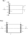
- a substantially cylindrical coil 1 of a transformer is clamped between a device according to the invention and a counter-holding element, not shown.
- the device according to the invention comprises a pressure element 2 and a hydraulic element 4 which is arranged between the pressure element 2 and a surface 9 of the spool 1 .
- the surface 9 is opposite a base 8 of the coil 1, on which base 8 the coil 1 is in engagement with the counter-holding element.
- the coil 1 in particular windings of the coil 1—is pressed between the counter-holding element and the device according to the invention.
- a pressing force is introduced via several force introduction points into the pressure element 2, which can be designed as a pressure plate or pressure ring, of the device and subsequently transmitted to the coil 1 via the hydraulic element 4 and the spacers 6.
- the pressing force has at least one component which acts on the coil 1 along an axial direction 3 of the coil 1, the The axial direction runs parallel to a longitudinal axis 5 of the coil 1 .
- FIG. 2 shows the arrangement 1 , A further device according to the invention being provided instead of the counter-holding element. This is therefore arranged on the base surface 8 of the spool 1 and also applies a pressing force to the spool 1, which acts on the spool 1 in the axial direction of the spool 1 and is thus directed in the opposite direction to the pressing force which is arranged on the surface 9 of the spool 1 Device is transferred to the coil 1.
- the amount of pressing forces transmitted via the two devices can be identical or different.
- the hydraulic elements 4 of the devices are connected to one another via a hydraulic connection 7, so that differences in the pressing forces acting on the two pressure elements 2 are compensated for due to the hydrostatic pressure equalization.
- the printing element 2 is in front of the plane of the drawing and is therefore not visible.
- the pressing force acts in each case in the axial direction 3, which is normal to the plane of the drawing and penetrates into it.
- the hydraulic element 4 of the device is formed by a single hydraulic hose. This is arranged to run spirally around the center point of the surface 9 or around the longitudinal axis 5 of the coil 1 and is provided with a single control device 10 .
- the hydraulic element 4 is formed by four concentrically arranged hydraulic hoses, which are connected to one another and to a single control device 10 via a hydraulic connection 7 .
- each of the hydraulic hoses can be subjected to a specific pressure separately.
- the hydraulic element 4 is formed by a plurality of arc-shaped hydraulic hoses and by a plurality of hydraulic cylinders.
- the individual hydraulic hoses can either be hydraulically connected to one another and provided with a common control device 10, or not connected to one another and each provided with its own control device 10; The same applies to the individual hydraulic cylinders.
- Separate hydraulic hoses and hydraulic cylinders can be applied separately with a specific pressure.
- the hydraulic element 4 is formed by a plurality of radially arranged hydraulic hoses.
- the individual hydraulic hoses are not connected to one another and are therefore each provided with their own control device 10 .
- the individual hydraulic hoses can each be separately subjected to a specific pressure.
- the embodiment variant according to 7 only a single control device 10, the individual hydraulic hoses being connected to one another via a hydraulic connection 7.
Landscapes
- Engineering & Computer Science (AREA)
- Power Engineering (AREA)
- Measuring Fluid Pressure (AREA)
- General Induction Heating (AREA)
Description
- Die Erfindung betrifft eine Vorrichtung zum Pressen eines eine oder mehrere Wicklungen aufweisenden Blockes einer statischen elektrischen Maschine, insbesondere einer Spule eines Transformators, umfassend ein Druckelement zur Übertragung einer in eine Axialrichtung des Blockes auf den Block wirkenden Presskraft.
- Des Weiteren betrifft die Erfindung eine statische elektrische Maschine, insbesondere einen elektrischen Transformator, umfassend zumindest einen eine oder mehrere Wicklungen aufweisenden Block sowie zumindest eine Vorrichtung der oben beschriebenen Art.
- Eine solche Vorrichtung ist aus der
DE 32 36 740 A1 bereits bekannt. Bei der dort offenbarten Vorrichtung wird die Presskraft von einer Zugstange erzeugt, die eine Pressplatte mit ihrem endseitigen Außengewinde durchgreift, so dass durch Aufschrauben einer Mutter auf das Außengewinde eine Spannkraft axial in die Wicklungsanordnung eingeleitet wird. Zwischen der Pressplatte und der Wicklungsanordnung ist ein pneumatischer Schlauch angeordnet. Umfasst die Wicklungsanordnung mehrere konzentrisch zueinander angeordnete Wicklungen ist für jede dieser Wicklungen ein pneumatischer Schlauch vorgesehen. - Die
DE 25 47 833 A1 beschreibt eine Vorrichtung, bei der die Spannkraft für die Wicklung durch Hydraulikzylinder erzeugt wird. - Um die für den sicheren Betrieb notwendige mechanische Stabilität von Spulen eines elektrischen Transformators sicherzustellen, werden diese in der Regel mechanisch gepresst.
- Zu diesem Zweck werden die meist zylinderförmigen Spulen an ihrer Grundfläche und einer dieser Grundfläche gegenüberliegenden Oberfläche bzw. Deckfläche zwischen zwei Druckelementen, beispielsweise Druckplatten bzw. -ringen, oder zwischen einem Druckelement und einem Gegenhalteelement gehalten und über die Druckelemente mit einer geeigneten Presskraft beaufschlagt. Die Presskraft wird dabei meist an mehreren Stellen in die Druckelemente eingeleitet und über auf der Ober- und/oder Grundfläche der Spule platzierte Abstandhalter auf die Spule übertragen.
- Aufgrund der lokalen Beaufschlagung der Druckplatte mit der Presskraft kommt es jedoch zu einer inhomogenen Verteilung des auf die Spule wirkenden Pressdruckes, was sich in einer Über- oder Unterpressung der Wicklungen äußern und die Lebensdauer des Transformators beeinträchtigen kann. Insbesondere im Falle einer Unterpressung können auch Probleme im Kurzschlussfall auftreten.
- Um eine homogenere Druckverteilung zu erreichen, sind mehrere Maßnahmen bekannt - etwa die Vergrößerung der Druckelemente, das Vorsehen zusätzlicher und breiterer Unterlagen an den Druckeinleitungsstellen, sowie die Erhöhung der Anzahl der Druckeinleitungsstellen. All diese Maßnahmen gehen jedoch mit einem erhöhten Aufwand in der Fertigung des jeweiligen Transformators einher und führen somit zu höheren Fertigungskosten.
- Es ist somit eine Aufgabe der Erfindung, die oben genannten Nachteile zu vermeiden und eine Vorrichtung zum Pressen eines eine oder mehrere Spulen oder Wicklungen aufweisenden Blockes einer statischen elektrischen Maschine, insbesondere eines Transformators, bereitzustellen, mittels welcher insbesondere die Unterpressung und Überpressung von Spulen oder Wicklungen des Blockes vermieden werden kann.
- Weitere der Erfindung zu Grunde liegenden Aufgaben werden aus der nachfolgenden Beschreibung der Erfindung deutlich.
- Eine Aufgabe der Erfindung wird durch eine Vorrichtung zum Pressen einer eine oder mehrere Spulen oder Wicklungen aufweisenden Blockes einer statischen elektrischen Maschine, insbesondere einer Spule eines Transformators, wobei die Vorrichtung ein Druckelement zur Übertragung einer in eine Axialrichtung des Blockes auf den Block wirkenden Presskraft umfasst, gelöst, indem die Vorrichtung zumindest ein Hydraulikelement zur Anordnung zwischen dem Druckelement und dem Block aufweist, um eine Verteilung eines auf den Block wirkenden Pressdruckes zu regeln. Etwa kann der Pressdruck gleichmäßiger verteilt oder aber gezielt in bestimmte Bereiche des Blockes eingeleitet werden.
- Im Kontext der vorliegenden Erfindung bezeichnet der Ausdruck "statische elektrische Maschine" elektrische Transformatoren oder Reaktoren.
- Durch die Verwendung des Hydraulikelementes zwischen dem Druckelement, welches beispielsweise als Druckplatte, Drucksegment, Drucksegmentkette, oder als Druckring ausgebildet sein kann, und dem Block, insbesondere einer Grund- oder Oberfläche einer im Wesentlichen zylinderförmigen Spule eines Transformators, kann durch den hydrostatischen Druckausgleich im Hydraulikelement bzw., im Falle mehrerer Hydraulikelemente, in allen Hydraulikelementen eine homogenisierte Verteilung des auf die Spule wirkenden Pressdruckes erreicht werden, wodurch unter anderem eine bessere Kurzschlussfestigkeit des Blockes, insbesondere der Spule, erreicht werden kann. Dadurch kann auch die Anzahl jener Stellen, an denen die Presskraft in das Druckelement eingeleitet wird, reduziert werden. Bei Blöcken, insbesondere Spulen, mit mehreren Wicklungen können alle Wicklungen mit dem gleichen Pressdruck beaufschlagt werden, oder es kann der auf jede einzelne Wicklung wirkende Pressdruck separat gewählt werden. Durch passive oder aktive Druckregelung in dem Hydraulikelement bzw. in den Hydraulikelementen können zudem Druckschwankungen gezielt kompensiert werden. Die Frequenzen dieser Druckschwankungen können dabei, im Rahmen der in statischen elektrischen Maschinen auftretenden Bereiche, beliebig hoch sein. Weiters wird es möglich, einen konstanten hydraulischen Pressdruck vorzugeben; durch den Einsatz einer mit dem Hydraulikelement in Wirkverbindung stehenden Regeleinrichtung kann ein für den Block, insbesondere die Spule, optimaler Pressdruck während der gesamten Lebenszeit der statischen elektrischen Maschine, insbesondere des Transformators, garantiert werden. Zusätzlich kann durch Regelung des auf den Block, insbesondere die Spule, wirkenden Pressdrucks das Schwingungsverhalten der Wicklungen gezielt beeinflusst werden, wodurch sich auch die Geräuschentwicklung der statischen elektrischen Maschine, insbesondere des Transformators, insgesamt beeinflussen lässt. Außerdem können, beispielsweise alterungsbedingte oder thermische, Druckschwankungen ausgeglichen werden; etwa durch den Einsatz von Piezoaktuatoren können so auch hochfrequente Druckschwankungen kompensiert werden. Durch Überwachung eines Betriebszustandes des Hydraulikelementes kann der im Betriebszustand der statischen elektrischen Maschine, insbesondere des Transformators, vorherrschende Pressdruck überwacht werden. Die Pressung des Blockes, insbesondere der Spule, kann erfolgen, indem eine einzige erfindungsgemäße Vorrichtung beispielsweise an die Grundfläche oder an die Oberfläche der Spule angebracht wird, oder indem eine erfindungsgemäße Vorrichtung an die Grundfläche der Spule und eine weitere erfindungsgemäße Vorrichtung an die der Grundfläche gegenüberliegende Oberfläche der Spule angebracht wird und die Presskraft über beide dieser erfindungsgemäßen Vorrichtungen in die Spule eingeleitet wird.
- Im Rahmen der Erfindung ist es vorgesehen, dass das Hydraulikelement durch zumindest einen Hydraulikschlauch ausgebildet ist.
- Sämtliche der im Folgenden im Zusammenhang mit der Spule eines Transformators getätigten Aussagen treffen analog im Zusammenhang mit dem eine oder mehrere Spulen oder Wicklungen umfassenden Block einer statischen elektrischen Maschine zu.
- Die Verwendung von Hydraulikschläuchen als Hydraulikelemente bietet sich vor allem aufgrund der hohen Flexibilität bei deren Anordnung zwischen Druckelement und Spule an. Je nachdem, ob die gesamte Grund- bzw. Oberfläche der Spule mit demselben Pressdruck beaufschlagt werden soll, oder ob einzelne Wicklungen gezielt mit einem erhöhten oder verringerten Pressdruck beaufschlagt werden sollen, kann die Anordnung des Hydraulikschlauches bzw., im Falle mehrerer Hydraulikschläuche, aller Hydraulikschläuche flexibel angepasst werden.
- Im Rahmen der Erfindung ist vorgesehen, dass der Hydraulikschlauch bezogen auf eine Längsachse der Spule spiralförmig verlaufend angeordnet ist.
- Durch diese erfindungsgemäße Maßnahme wird es möglich, die gesamte Grund- bzw. Oberfläche der Spule mittels eines einzigen Hydraulikschlauches mit demselben Pressdruck zu beaufschlagen. Dabei kann der Hydraulikschlauch von einem Zentrum der Spule spiralförmig in Richtung einer die Grund- bzw. Oberfläche abschließenden Mantelkante der Spule verlaufend angeordnet sein. Das gesamte Hydraulikelement kann dabei mittels einer einzigen Regeleinrichtung geregelt werden.
- Eine der Erfindung zu Grunde liegende Aufgabe wird auch durch einen Transformator umfassend zumindest eine Spule sowie zumindest eine Vorrichtung der vorhergehend beschriebenen Art gelöst, wobei das zumindest eine, vorzugsweise jedes, Hydraulikelement zwischen dem Druckelement und der Spule gepresst ist.
- Dabei wird die in das Druckelement eingeleitete Presskraft über das Hydraulikelement, also beispielsweise über einen oder mehrere Hydraulikschläuche oder über eine Kombinationsanordnung von Hydraulikschläuchen und -zylindern, auf die Spule übertragen. Durch den Einsatz des erfindungsgemäßen Hydraulikelementes kann eine über die Grund- bzw. Oberfläche der Spule besonders homogene Verteilung des resultierenden, auf die Spule wirkenden Pressdruckes erreicht werden.
- Besonders bevorzugt ist zwischen dem Hydraulikelement und der Spule zumindest ein, vorzugsweise mehrere, Abstandhalter angeordnet.
- Bei den Abstandhaltern handelt es sich um im Vergleich zu dem Hydraulikelement formstarre Elemente, welche zwischen dem Hydraulikelement und den einzelnen Windungen der Spule angeordnet sind, um die Kraftübertragung auf die Spule zu optimieren sowie einen im Betriebszustand des Transformators zur Kühlung nötigen Ölfluss zuzulassen.
- Im Folgenden wird die Erfindung anhand von Ausführungsbeispielen näher erläutert. Die Zeichnungen, auf die dabei Bezug genommen wird, sind beispielhaft und sollen die Erfindung zwar darlegen, sie aber keinesfalls einengen oder gar abschließend wiedergeben.
- Die Zeichnungen stellen die Vorrichtung auf einem Transformatorschenkel eines Aktivteils dar. Dabei zeigt
- Fig. 1
- eine schematische Darstellung einer Spule eines elektrischen Transformators mit einer an der Oberfläche der Spule angebrachten Vorrichtung,
- Fig. 2
- eine schematische Darstellung einer Spule eines elektrischen Transformators mit einer an der Oberfläche der Spule angebrachten Vorrichtung sowie einer weiteren, an der Grundfläche der Spule angebrachten Vorrichtung,
- Fig. 3
- eine Schnittansicht gemäß Schnittlinie A-A aus
Fig. 1 einer erfindungsgemäßen Ausführungsvariante, wobei das Hydraulikelement durch einen spiralförmig angeordneten Hydraulikschlauch ausgebildet ist, - Fig. 4
- eine Schnittansicht gemäß Schnittlinie A-A aus
Fig. 1 einer Ausführungsvariante, die nicht teil der Erfindung wie beansprucht ist, - wobei
- das Hydraulikelement durch konzentrisch angeordnete Hydraulikschläuche ausgebildet ist,
- Fig. 5
- eine Schnittansicht gemäß Schnittlinie A-A aus
Fig. 1 einer Ausführungsvariante, die nicht teil der Erfindung wie beansprucht ist, wobei das Hydraulikelement durch mehrere kreisbogenförmige Hydraulikschläuche sowie durch mehrere Hydraulikzylinder ausgebildet ist, - Fig. 6
- eine Schnittansicht gemäß Schnittlinie A-A aus Fig. nicht teil 1 einer Ausführungsvariante, die der Erfindung wie beansprucht ist, wobei das Hydraulikelement durch mehrere radial verlaufend angeordnete Hydraulikschläuche ausgebildet ist, und
- Fig. 7
- eine Schnittansicht gemäß Schnittlinie A-A aus
Fig. 1 einer Ausführungsvariante, die nicht teil der Erfindung wie beansprucht ist, wobei das Hydraulikelement durch mehrere radial verlaufend angeordnete und hydraulisch miteinander verbundene Hydraulikschläuche ausgebildet ist. - Die grundsätzliche Funktionsweise der erfindungsgemäßen Vorrichtung wird durch
Fig. 1 veranschaulicht. Eine im Wesentlichen zylinderförmige Spule 1 eines Transformators ist dabei zwischen einer erfindungsgemäßen Vorrichtung und einem nicht dargestellten Gegenhalteelement eingespannt. - Die erfindungsgemäße Vorrichtung umfasst ein Druckelement 2 sowie ein Hydraulikelement 4, welches zwischen dem Druckelement 2 und einer Oberfläche 9 der Spule 1 angeordnet ist. Die Oberfläche 9 liegt einer Grundfläche 8 der Spule 1 gegenüber, an welcher Grundfläche 8 die Spule 1 mit dem Gegenhalteelement in Eingriff steht. Zwischen dem Hydraulikelement 4 und der Oberfläche 9 der Spule 1 befinden sich mehrere Abstandhalter 6, welche im Vergleich zu dem Hydraulikelement 4 formstarr ausgebildet sind.
- Um der Spule 1 die für einen sicheren Betrieb des Transformators erforderliche mechanische Stabilität zu verleihen, wird die Spule 1 - insbesondere Wicklungen der Spule 1 - zwischen dem Gegenhalteelement und der erfindungsgemäßen Vorrichtung gepresst. Dazu wird eine Presskraft über mehrere Krafteinleitungsstellen in das Druckelement 2, welches als Druckplatte oder Druckring ausgebildet sein kann, der Vorrichtung eingeleitet und in weiterer Folge über das Hydraulikelement 4 und die Abstandhalter 6 auf die Spule 1 übertragen. Die Presskraft hat dabei zumindest eine Komponente, welche entlang einer Axialrichtung 3 der Spule 1 auf die Spule 1 wirkt, wobei die Axialrichtung parallel zu einer Längsachse 5 der Spule 1 verläuft.
- Durch den Einsatz des Hydraulikelementes 4 kann eine verglichen mit herkömmlichen Pressvorrichtungen homogene Verteilung des resultierenden Pressdruckes, welcher auf die Spule 1 bzw. auf die Oberfläche 9 der Spule 1 wirkt, erzielt werden. Dies wird insbesondere aufgrund des hydrostatischen Druckausgleichs im Hydraulikelement bzw., im Falle mehrerer Hydraulikelemente, in allen Hydraulikelementen erreicht.
-
Fig. 2 zeigt die Anordnung ausFig. 1 , wobei anstelle des Gegenhalteelementes eine weitere erfindungsgemäße Vorrichtung vorgesehen ist. Diese ist demnach an der Grundfläche 8 der Spule 1 angeordnet und beaufschlagt die Spule 1 ebenfalls mit einer Presskraft, welche in Axialrichtung der Spule 1 auf die Spule 1 wirkt und somit jener Presskraft entgegengerichtet ist, welche über die auf der Oberfläche 9 der Spule 1 angeordnete Vorrichtung auf die Spule 1 übertragen wird. - Grundsätzlich können die über die beiden Vorrichtungen übertragenen Presskräfte betragsmäßig identisch oder verschieden sein. In dem in
Fig. 2 dargestellten Ausführungsbeispiel sind die Hydraulikelemente 4 der Vorrichtungen über eine hydraulische Verbindung 7 miteinander Verbunden, sodass aufgrund des hydrostatischen Druckausgleiches Unterschiede in den auf die beiden Druckelemente 2 wirkenden Presskräften ausgeglichen werden. - Die
Fig. 3, 4, 5, 6 und 7 zeigen jeweils eine Schnittansicht gemäß Schnittlinie A-A (sieheFig. 1 ), jedoch jeweils für unterschiedliche Ausführungsvarianten der - Vorrichtung. Jedoch zeigt nur
Fig. 3 eine erfindungsgemäße Ausführungsvariante. Das Druckelement 2 liegt dabei vor der Zeichenebene und ist daher nicht zu sehen. Die Presskraft wirkt jeweils in Axialrichtung 3, welche normal auf die Zeichenebene steht und in diese eindringt. - In
Fig. 3 ist das Hydraulikelement 4 der Vorrichtung durch einen einzigen Hydraulikschlauch ausgebildet. Dieser ist spiralförmig verlaufend um den Mittelpunkt der Oberfläche 9 bzw. um die Längsachse 5 der Spule 1 angeordnet und mit einer einzigen Regeleinrichtung 10 versehen. - In
Fig. 4 ist das Hydraulikelement 4 durch vier konzentrisch angeordnete Hydraulikschläuche ausgebildet, welche über eine hydraulische Verbindung 7 miteinander sowie mit einer einzigen Regeleinrichtung 10 verbunden sind. - Es sind jedoch auch solche,
Fig. 4 entsprechenden Ausführungsbeispiele erfasst, bei denen die konzentrischen Hydraulikschläuche nicht miteinander verbunden sind und jeder Hydraulikschlauch mit einer eigenen Regeleinrichtung 10 versehen ist. Somit kann jeder einzelne der Hydraulikschläuche separat mit einem bestimmten Pressdruck beaufschlagt werden. - In
Fig. 5 ist das Hydraulikelement 4 durch mehrere kreisbogenförmige Hydraulikschläuche sowie durch mehrere Hydraulikzylinder ausgebildet. Dabei können die einzelnen Hydraulikschläuche entweder hydraulisch miteinander verbunden und mit einer gemeinsamen Regeleinrichtung 10 versehen sein, oder aber nicht miteinander verbunden und jeweils mit einer eigenen Regeleinrichtung 10 versehen sein; Selbiges gilt für die einzelnen Hydraulikzylinder. Separate Hydraulikschläuche und Hydraulikzylinder können dabei separat mit einem bestimmten Pressdruck beaufschlagt werden. - In
Fig. 6 und Fig. 7 ist das Hydraulikelement 4 durch mehrere radial verlaufend angeordnete Hydraulikschläuche ausgebildet. In der inFig. 6 abgebildeten Ausführungsvariante sind die einzelnen Hydraulikschläuche nicht miteinander verbunden und sind daher jeweils mit einer eigenen Regeleinrichtung 10 versehen. Hier können die einzelnen Hydraulikschläuche jeweils separat mit einem bestimmten Pressdruck beaufschlagt werden. Hingegen umfasst die Ausführungsvariante gemäßFig. 7 lediglich eine einzige Regeleinrichtung 10, wobei die einzelnen Hydraulikschläuche über eine hydraulische Verbindung 7 miteinander verbunden sind. -
- 1
- Spule
- 2
- Druckelement
- 3
- Axialrichtung
- 4
- Hydraulikelement
- 5
- Längsachse
- 6
- Abstandhalter
- 7
- hydraulische Verbindung
- 8
- Grundfläche
- 9
- Oberfläche
- 10
- Regeleinrichtung
Claims (5)
- Vorrichtung zum Pressen eines eine oder mehrere Wicklungen aufweisenden Blockes einer statischen elektrischen Maschine, vorzugsweise einer Spule (1) eines Transformators, umfassend ein Druckelement (2) zur Übertragung einer in eine Axialrichtung (3) des Blockes auf den Block wirkenden Presskraft, wobei die Vorrichtung zumindest ein Hydraulikelement (4) zur Anordnung zwischen dem Druckelement (2) und dem Block aufweist, um eine Verteilung eines auf den Block wirkenden Pressdruckes zu regeln, dadurch gekennzeichnet, dass das Hydraulikelement (4) durch zumindest einen Hydraulikschlauch ausgebildet und der Hydraulikschlauch bezogen auf eine Längsachse (5) des Blockes spiralförmig verlaufend angeordnet ist.
- Statische elektrische Maschine umfassend zumindest einen eine oder mehrere Wicklungen aufweisenden Block, sowie zumindest eine Vorrichtung nach Anspruch 1, wobei das zumindest eine, vorzugsweise jedes, Hydraulikelement (4) zwischen dem Druckelement (2) und dem Block gepresst ist.
- Statische elektrische Maschine nach Anspruch 2, dadurch gekennzeichnet, dass zwischen dem Hydraulikelement (4) und dem Block zumindest ein, vorzugsweise mehrere, Abstandhalter (6) angeordnet sind.
- Statische elektrische Maschine nach einem der Ansprüche 2 oder 3, wobei diese als elektrischer Transformator ausgebildet ist und wobei der Block als Spule (1) des Transformators ausgebildet ist.
- Statische elektrische Maschine nach einem der Ansprüche 2 oder 3, wobei diese als elektrischer Reaktor ausgebildet ist und wobei der Block als Spule (1) des Reaktors ausgebildet ist.
Priority Applications (1)
| Application Number | Priority Date | Filing Date | Title |
|---|---|---|---|
| EP19154693.6A EP3690902B1 (de) | 2019-01-31 | 2019-01-31 | Vorrichtung zum pressen eines eine oder mehrere wicklungen aufweisenden blockes einer statischen elektrischen maschine |
Applications Claiming Priority (1)
| Application Number | Priority Date | Filing Date | Title |
|---|---|---|---|
| EP19154693.6A EP3690902B1 (de) | 2019-01-31 | 2019-01-31 | Vorrichtung zum pressen eines eine oder mehrere wicklungen aufweisenden blockes einer statischen elektrischen maschine |
Publications (2)
| Publication Number | Publication Date |
|---|---|
| EP3690902A1 EP3690902A1 (de) | 2020-08-05 |
| EP3690902B1 true EP3690902B1 (de) | 2022-08-10 |
Family
ID=65275957
Family Applications (1)
| Application Number | Title | Priority Date | Filing Date |
|---|---|---|---|
| EP19154693.6A Active EP3690902B1 (de) | 2019-01-31 | 2019-01-31 | Vorrichtung zum pressen eines eine oder mehrere wicklungen aufweisenden blockes einer statischen elektrischen maschine |
Country Status (1)
| Country | Link |
|---|---|
| EP (1) | EP3690902B1 (de) |
Family Cites Families (4)
| Publication number | Priority date | Publication date | Assignee | Title |
|---|---|---|---|---|
| SE386534B (sv) * | 1974-11-08 | 1976-08-09 | Asea Ab | Anordning for inspenning av transformatorlindningar pa hydraulisk veg |
| JPS5749211A (en) * | 1980-09-08 | 1982-03-23 | Mitsubishi Electric Corp | Electromagnetic induction device |
| DE3236740C2 (de) * | 1982-10-04 | 1984-08-09 | Schorch GmbH, 4050 Mönchengladbach | Vorrichtung zum Pressen von Wicklungen von Transformatoren und Drosselspulen |
| JPS59121816A (ja) * | 1982-12-27 | 1984-07-14 | Toshiba Corp | 巻線締付装置 |
-
2019
- 2019-01-31 EP EP19154693.6A patent/EP3690902B1/de active Active
Also Published As
| Publication number | Publication date |
|---|---|
| EP3690902A1 (de) | 2020-08-05 |
Similar Documents
| Publication | Publication Date | Title |
|---|---|---|
| EP3189237B1 (de) | Exzenterschneckenpumpe | |
| DE19513457A1 (de) | Rotor einer elektrischen Maschine | |
| DE102010016701A1 (de) | Leiteinrichtungen zur Kühlung von Generatorspulen | |
| EP2878722B1 (de) | Verfahren zur Steuerung der Fadenlieferung, Fadenliefergerät und System mit Fadenliefergeräten | |
| EP3122999B1 (de) | Ringförmige spannmutter für einen zuganker | |
| EP2850719B1 (de) | Statoranordnung für eine elektrische maschine | |
| EP2463538B1 (de) | Schrumpfscheibe zur reibschlüssigen Verbindung von rotierenden Maschinenteilen | |
| DE102004046107A1 (de) | Sensor | |
| EP3690902B1 (de) | Vorrichtung zum pressen eines eine oder mehrere wicklungen aufweisenden blockes einer statischen elektrischen maschine | |
| EP3140552B1 (de) | Hydraulikflachzylinder, hydraulikhubkissen, verwendung eines solchen und verfahren zum ausrichten eines generators | |
| DE102013224552A1 (de) | Vorrichtung und Verfahren zum Nachsetzen einer Elektrode für einen metallurgischen Ofen | |
| EP3111745A1 (de) | Reparatur-, umbau- bzw. nachrüstsatz für eine rundballenpresse | |
| EP3756820A1 (de) | Nullpunktspannsystem für werkzeugmaschinen, insbesondere dreh- und/oder fräsmaschinen | |
| DE10310306A1 (de) | Vorrichtung zum Spannen einer Statorwicklung | |
| WO2021004676A1 (de) | Rotor für eine elektrische maschine | |
| DE10208933A1 (de) | Spulspindel | |
| WO2010012366A2 (de) | Magnetlager und verfahren zu dessen betrieb | |
| EP3058121A1 (de) | Doppelfriktionsaggregat mit verstellbaren friktionsspindeln | |
| WO2023088732A1 (de) | Elektrische maschine, insbesondere elektrische maschine für ein kraftfahrzeug | |
| DE102017003424A1 (de) | Spritzgiessmaschine, die einen Temperaturregelungsmantel umfasst | |
| DE102018120322A1 (de) | Spinn- oder Spulmaschine und Methode zum Betreiben einer Spinn- oder Spulmaschine | |
| WO2023156206A1 (de) | Wickelkopfhalterung eines rotors für eine elektrische maschine | |
| WO2023156370A1 (de) | Rotor für eine elektrische maschine | |
| DE102017127771A1 (de) | Steuerung der Faserstoffbehandlung | |
| WO2010102922A1 (de) | Vorrichtung zum axialen spannen einer statorwicklung einer elektrischen maschine |
Legal Events
| Date | Code | Title | Description |
|---|---|---|---|
| PUAI | Public reference made under article 153(3) epc to a published international application that has entered the european phase |
Free format text: ORIGINAL CODE: 0009012 |
|
| STAA | Information on the status of an ep patent application or granted ep patent |
Free format text: STATUS: THE APPLICATION HAS BEEN PUBLISHED |
|
| AK | Designated contracting states |
Kind code of ref document: A1 Designated state(s): AL AT BE BG CH CY CZ DE DK EE ES FI FR GB GR HR HU IE IS IT LI LT LU LV MC MK MT NL NO PL PT RO RS SE SI SK SM TR |
|
| AX | Request for extension of the european patent |
Extension state: BA ME |
|
| RAP1 | Party data changed (applicant data changed or rights of an application transferred) |
Owner name: SIEMENS ENERGY GLOBAL GMBH & CO. KG |
|
| STAA | Information on the status of an ep patent application or granted ep patent |
Free format text: STATUS: REQUEST FOR EXAMINATION WAS MADE |
|
| 17P | Request for examination filed |
Effective date: 20210208 |
|
| RBV | Designated contracting states (corrected) |
Designated state(s): AL AT BE BG CH CY CZ DE DK EE ES FI FR GB GR HR HU IE IS IT LI LT LU LV MC MK MT NL NO PL PT RO RS SE SI SK SM TR |
|
| GRAP | Despatch of communication of intention to grant a patent |
Free format text: ORIGINAL CODE: EPIDOSNIGR1 |
|
| STAA | Information on the status of an ep patent application or granted ep patent |
Free format text: STATUS: GRANT OF PATENT IS INTENDED |
|
| INTG | Intention to grant announced |
Effective date: 20220321 |
|
| GRAS | Grant fee paid |
Free format text: ORIGINAL CODE: EPIDOSNIGR3 |
|
| GRAA | (expected) grant |
Free format text: ORIGINAL CODE: 0009210 |
|
| STAA | Information on the status of an ep patent application or granted ep patent |
Free format text: STATUS: THE PATENT HAS BEEN GRANTED |
|
| AK | Designated contracting states |
Kind code of ref document: B1 Designated state(s): AL AT BE BG CH CY CZ DE DK EE ES FI FR GB GR HR HU IE IS IT LI LT LU LV MC MK MT NL NO PL PT RO RS SE SI SK SM TR |
|
| REG | Reference to a national code |
Ref country code: AT Ref legal event code: REF Ref document number: 1511162 Country of ref document: AT Kind code of ref document: T Effective date: 20220815 Ref country code: CH Ref legal event code: EP |
|
| REG | Reference to a national code |
Ref country code: IE Ref legal event code: FG4D Free format text: LANGUAGE OF EP DOCUMENT: GERMAN |
|
| REG | Reference to a national code |
Ref country code: DE Ref legal event code: R096 Ref document number: 502019005199 Country of ref document: DE |
|
| REG | Reference to a national code |
Ref country code: SE Ref legal event code: TRGR |
|
| REG | Reference to a national code |
Ref country code: NL Ref legal event code: FP |
|
| REG | Reference to a national code |
Ref country code: LT Ref legal event code: MG9D |
|
| PG25 | Lapsed in a contracting state [announced via postgrant information from national office to epo] |
Ref country code: RS Free format text: LAPSE BECAUSE OF FAILURE TO SUBMIT A TRANSLATION OF THE DESCRIPTION OR TO PAY THE FEE WITHIN THE PRESCRIBED TIME-LIMIT Effective date: 20220810 Ref country code: PT Free format text: LAPSE BECAUSE OF FAILURE TO SUBMIT A TRANSLATION OF THE DESCRIPTION OR TO PAY THE FEE WITHIN THE PRESCRIBED TIME-LIMIT Effective date: 20221212 Ref country code: NO Free format text: LAPSE BECAUSE OF FAILURE TO SUBMIT A TRANSLATION OF THE DESCRIPTION OR TO PAY THE FEE WITHIN THE PRESCRIBED TIME-LIMIT Effective date: 20221110 Ref country code: LV Free format text: LAPSE BECAUSE OF FAILURE TO SUBMIT A TRANSLATION OF THE DESCRIPTION OR TO PAY THE FEE WITHIN THE PRESCRIBED TIME-LIMIT Effective date: 20220810 Ref country code: LT Free format text: LAPSE BECAUSE OF FAILURE TO SUBMIT A TRANSLATION OF THE DESCRIPTION OR TO PAY THE FEE WITHIN THE PRESCRIBED TIME-LIMIT Effective date: 20220810 Ref country code: FI Free format text: LAPSE BECAUSE OF FAILURE TO SUBMIT A TRANSLATION OF THE DESCRIPTION OR TO PAY THE FEE WITHIN THE PRESCRIBED TIME-LIMIT Effective date: 20220810 |
|
| PG25 | Lapsed in a contracting state [announced via postgrant information from national office to epo] |
Ref country code: PL Free format text: LAPSE BECAUSE OF FAILURE TO SUBMIT A TRANSLATION OF THE DESCRIPTION OR TO PAY THE FEE WITHIN THE PRESCRIBED TIME-LIMIT Effective date: 20220810 Ref country code: IS Free format text: LAPSE BECAUSE OF FAILURE TO SUBMIT A TRANSLATION OF THE DESCRIPTION OR TO PAY THE FEE WITHIN THE PRESCRIBED TIME-LIMIT Effective date: 20221210 Ref country code: HR Free format text: LAPSE BECAUSE OF FAILURE TO SUBMIT A TRANSLATION OF THE DESCRIPTION OR TO PAY THE FEE WITHIN THE PRESCRIBED TIME-LIMIT Effective date: 20220810 Ref country code: GR Free format text: LAPSE BECAUSE OF FAILURE TO SUBMIT A TRANSLATION OF THE DESCRIPTION OR TO PAY THE FEE WITHIN THE PRESCRIBED TIME-LIMIT Effective date: 20221111 |
|
| PG25 | Lapsed in a contracting state [announced via postgrant information from national office to epo] |
Ref country code: SM Free format text: LAPSE BECAUSE OF FAILURE TO SUBMIT A TRANSLATION OF THE DESCRIPTION OR TO PAY THE FEE WITHIN THE PRESCRIBED TIME-LIMIT Effective date: 20220810 Ref country code: RO Free format text: LAPSE BECAUSE OF FAILURE TO SUBMIT A TRANSLATION OF THE DESCRIPTION OR TO PAY THE FEE WITHIN THE PRESCRIBED TIME-LIMIT Effective date: 20220810 Ref country code: ES Free format text: LAPSE BECAUSE OF FAILURE TO SUBMIT A TRANSLATION OF THE DESCRIPTION OR TO PAY THE FEE WITHIN THE PRESCRIBED TIME-LIMIT Effective date: 20220810 Ref country code: DK Free format text: LAPSE BECAUSE OF FAILURE TO SUBMIT A TRANSLATION OF THE DESCRIPTION OR TO PAY THE FEE WITHIN THE PRESCRIBED TIME-LIMIT Effective date: 20220810 Ref country code: CZ Free format text: LAPSE BECAUSE OF FAILURE TO SUBMIT A TRANSLATION OF THE DESCRIPTION OR TO PAY THE FEE WITHIN THE PRESCRIBED TIME-LIMIT Effective date: 20220810 |
|
| PGFP | Annual fee paid to national office [announced via postgrant information from national office to epo] |
Ref country code: FR Payment date: 20230113 Year of fee payment: 5 |
|
| REG | Reference to a national code |
Ref country code: DE Ref legal event code: R097 Ref document number: 502019005199 Country of ref document: DE |
|
| PG25 | Lapsed in a contracting state [announced via postgrant information from national office to epo] |
Ref country code: SK Free format text: LAPSE BECAUSE OF FAILURE TO SUBMIT A TRANSLATION OF THE DESCRIPTION OR TO PAY THE FEE WITHIN THE PRESCRIBED TIME-LIMIT Effective date: 20220810 Ref country code: EE Free format text: LAPSE BECAUSE OF FAILURE TO SUBMIT A TRANSLATION OF THE DESCRIPTION OR TO PAY THE FEE WITHIN THE PRESCRIBED TIME-LIMIT Effective date: 20220810 |
|
| PGFP | Annual fee paid to national office [announced via postgrant information from national office to epo] |
Ref country code: SE Payment date: 20230109 Year of fee payment: 5 |
|
| PLBE | No opposition filed within time limit |
Free format text: ORIGINAL CODE: 0009261 |
|
| STAA | Information on the status of an ep patent application or granted ep patent |
Free format text: STATUS: NO OPPOSITION FILED WITHIN TIME LIMIT |
|
| PG25 | Lapsed in a contracting state [announced via postgrant information from national office to epo] |
Ref country code: AL Free format text: LAPSE BECAUSE OF FAILURE TO SUBMIT A TRANSLATION OF THE DESCRIPTION OR TO PAY THE FEE WITHIN THE PRESCRIBED TIME-LIMIT Effective date: 20220810 |
|
| 26N | No opposition filed |
Effective date: 20230511 |
|
| PG25 | Lapsed in a contracting state [announced via postgrant information from national office to epo] |
Ref country code: SI Free format text: LAPSE BECAUSE OF FAILURE TO SUBMIT A TRANSLATION OF THE DESCRIPTION OR TO PAY THE FEE WITHIN THE PRESCRIBED TIME-LIMIT Effective date: 20220810 |
|
| REG | Reference to a national code |
Ref country code: CH Ref legal event code: PL |
|
| PG25 | Lapsed in a contracting state [announced via postgrant information from national office to epo] |
Ref country code: LU Free format text: LAPSE BECAUSE OF NON-PAYMENT OF DUE FEES Effective date: 20230131 |
|
| REG | Reference to a national code |
Ref country code: BE Ref legal event code: MM Effective date: 20230131 |
|
| PG25 | Lapsed in a contracting state [announced via postgrant information from national office to epo] |
Ref country code: LI Free format text: LAPSE BECAUSE OF NON-PAYMENT OF DUE FEES Effective date: 20230131 Ref country code: CH Free format text: LAPSE BECAUSE OF NON-PAYMENT OF DUE FEES Effective date: 20230131 |
|
| PG25 | Lapsed in a contracting state [announced via postgrant information from national office to epo] |
Ref country code: BE Free format text: LAPSE BECAUSE OF NON-PAYMENT OF DUE FEES Effective date: 20230131 |
|
| PG25 | Lapsed in a contracting state [announced via postgrant information from national office to epo] |
Ref country code: IE Free format text: LAPSE BECAUSE OF NON-PAYMENT OF DUE FEES Effective date: 20230131 |
|
| PGFP | Annual fee paid to national office [announced via postgrant information from national office to epo] |
Ref country code: NL Payment date: 20240125 Year of fee payment: 6 |
|
| PGFP | Annual fee paid to national office [announced via postgrant information from national office to epo] |
Ref country code: DE Payment date: 20240129 Year of fee payment: 6 Ref country code: GB Payment date: 20240123 Year of fee payment: 6 |