EP3690837A1 - Flexibles flächenelement mit sensorstruktur aus elektrischen leitern - Google Patents
Flexibles flächenelement mit sensorstruktur aus elektrischen leitern Download PDFInfo
- Publication number
- EP3690837A1 EP3690837A1 EP20152096.2A EP20152096A EP3690837A1 EP 3690837 A1 EP3690837 A1 EP 3690837A1 EP 20152096 A EP20152096 A EP 20152096A EP 3690837 A1 EP3690837 A1 EP 3690837A1
- Authority
- EP
- European Patent Office
- Prior art keywords
- surface element
- flexible surface
- radio
- evaluation unit
- electrically conductive
- Prior art date
- Legal status (The legal status is an assumption and is not a legal conclusion. Google has not performed a legal analysis and makes no representation as to the accuracy of the status listed.)
- Granted
Links
Images

Classifications
-
- B—PERFORMING OPERATIONS; TRANSPORTING
- B60—VEHICLES IN GENERAL
- B60R—VEHICLES, VEHICLE FITTINGS, OR VEHICLE PARTS, NOT OTHERWISE PROVIDED FOR
- B60R25/00—Fittings or systems for preventing or indicating unauthorised use or theft of vehicles
- B60R25/10—Fittings or systems for preventing or indicating unauthorised use or theft of vehicles actuating a signalling device
- B60R25/1004—Alarm systems characterised by the type of sensor, e.g. current sensing means
-
- A—HUMAN NECESSITIES
- A45—HAND OR TRAVELLING ARTICLES
- A45C—PURSES; LUGGAGE; HAND CARRIED BAGS
- A45C13/00—Details; Accessories
- A45C13/18—Devices to prevent theft or loss of purses, luggage or hand carried bags
-
- B—PERFORMING OPERATIONS; TRANSPORTING
- B60—VEHICLES IN GENERAL
- B60R—VEHICLES, VEHICLE FITTINGS, OR VEHICLE PARTS, NOT OTHERWISE PROVIDED FOR
- B60R25/00—Fittings or systems for preventing or indicating unauthorised use or theft of vehicles
- B60R25/01—Fittings or systems for preventing or indicating unauthorised use or theft of vehicles operating on vehicle systems or fittings, e.g. on doors, seats or windscreens
-
- B—PERFORMING OPERATIONS; TRANSPORTING
- B60—VEHICLES IN GENERAL
- B60R—VEHICLES, VEHICLE FITTINGS, OR VEHICLE PARTS, NOT OTHERWISE PROVIDED FOR
- B60R25/00—Fittings or systems for preventing or indicating unauthorised use or theft of vehicles
- B60R25/10—Fittings or systems for preventing or indicating unauthorised use or theft of vehicles actuating a signalling device
- B60R25/102—Fittings or systems for preventing or indicating unauthorised use or theft of vehicles actuating a signalling device a signal being sent to a remote location, e.g. a radio signal being transmitted to a police station, a security company or the owner
-
- D—TEXTILES; PAPER
- D03—WEAVING
- D03D—WOVEN FABRICS; METHODS OF WEAVING; LOOMS
- D03D1/00—Woven fabrics designed to make specified articles
- D03D1/0088—Fabrics having an electronic function
-
- D—TEXTILES; PAPER
- D04—BRAIDING; LACE-MAKING; KNITTING; TRIMMINGS; NON-WOVEN FABRICS
- D04H—MAKING TEXTILE FABRICS, e.g. FROM FIBRES OR FILAMENTARY MATERIAL; FABRICS MADE BY SUCH PROCESSES OR APPARATUS, e.g. FELTS, NON-WOVEN FABRICS; COTTON-WOOL; WADDING ; NON-WOVEN FABRICS FROM STAPLE FIBRES, FILAMENTS OR YARNS, BONDED WITH AT LEAST ONE WEB-LIKE MATERIAL DURING THEIR CONSOLIDATION
- D04H1/00—Non-woven fabrics formed wholly or mainly of staple fibres or like relatively short fibres
- D04H1/40—Non-woven fabrics formed wholly or mainly of staple fibres or like relatively short fibres from fleeces or layers composed of fibres without existing or potential cohesive properties
- D04H1/42—Non-woven fabrics formed wholly or mainly of staple fibres or like relatively short fibres from fleeces or layers composed of fibres without existing or potential cohesive properties characterised by the use of certain kinds of fibres insofar as this use has no preponderant influence on the consolidation of the fleece
- D04H1/4209—Inorganic fibres
- D04H1/4234—Metal fibres
-
- G—PHYSICS
- G08—SIGNALLING
- G08B—SIGNALLING OR CALLING SYSTEMS; ORDER TELEGRAPHS; ALARM SYSTEMS
- G08B13/00—Burglar, theft or intruder alarms
- G08B13/02—Mechanical actuation
- G08B13/12—Mechanical actuation by the breaking or disturbance of stretched cords or wires
- G08B13/126—Mechanical actuation by the breaking or disturbance of stretched cords or wires for a housing, e.g. a box, a safe, or a room
-
- A—HUMAN NECESSITIES
- A45—HAND OR TRAVELLING ARTICLES
- A45C—PURSES; LUGGAGE; HAND CARRIED BAGS
- A45C13/00—Details; Accessories
- A45C13/18—Devices to prevent theft or loss of purses, luggage or hand carried bags
- A45C13/24—Devices for sound-producing, piercing, gas-discharging, or the like
-
- D—TEXTILES; PAPER
- D10—INDEXING SCHEME ASSOCIATED WITH SUBLASSES OF SECTION D, RELATING TO TEXTILES
- D10B—INDEXING SCHEME ASSOCIATED WITH SUBLASSES OF SECTION D, RELATING TO TEXTILES
- D10B2401/00—Physical properties
- D10B2401/16—Physical properties antistatic; conductive
-
- D—TEXTILES; PAPER
- D10—INDEXING SCHEME ASSOCIATED WITH SUBLASSES OF SECTION D, RELATING TO TEXTILES
- D10B—INDEXING SCHEME ASSOCIATED WITH SUBLASSES OF SECTION D, RELATING TO TEXTILES
- D10B2401/00—Physical properties
- D10B2401/18—Physical properties including electronic components
-
- D—TEXTILES; PAPER
- D10—INDEXING SCHEME ASSOCIATED WITH SUBLASSES OF SECTION D, RELATING TO TEXTILES
- D10B—INDEXING SCHEME ASSOCIATED WITH SUBLASSES OF SECTION D, RELATING TO TEXTILES
- D10B2403/00—Details of fabric structure established in the fabric forming process
- D10B2403/02—Cross-sectional features
- D10B2403/024—Fabric incorporating additional compounds
- D10B2403/0243—Fabric incorporating additional compounds enhancing functional properties
- D10B2403/02431—Fabric incorporating additional compounds enhancing functional properties with electronic components, e.g. sensors or switches
-
- D—TEXTILES; PAPER
- D10—INDEXING SCHEME ASSOCIATED WITH SUBLASSES OF SECTION D, RELATING TO TEXTILES
- D10B—INDEXING SCHEME ASSOCIATED WITH SUBLASSES OF SECTION D, RELATING TO TEXTILES
- D10B2505/00—Industrial
- D10B2505/18—Outdoor fabrics, e.g. tents, tarpaulins
Definitions
- the invention relates to a flexible surface element according to the preamble of claim 1.
- Such a flexible surface element generally has a sensor structure with an evaluation unit which is designed to detect incisions in the flexible surface element. This means that these surface elements can be used to ensure protection against burglary, theft and vandalism. This generally ensures that the flexible surface element is protected against unauthorized interference. Accordingly, objects encased with the flexible surface element can be protected against unauthorized interference.
- Such a flexible surface element is from the WO 2018/113993 known.
- the flexible surface element described there comprises sensor structures and cut-resistant structures which are incorporated into the flexible surface element as sensor threads or cut-resistant threads as cut-resistant structure by means of a warp knitting machine or Raschel machine.
- the cut-resistant structure generally provides mechanical protection against puncturing the surface element with objects such as knives or similar sharp-edged objects.
- the cut-resistant structures are designed in such a way that at most only local puncturing into the surface element is possible, but not a large-scale separation of the surface element. Furthermore, a puncturing of the surface element with the sensor structure is detected, so that, for example, an alarm signal is then generated which reports the unauthorized intervention on the surface element.
- the invention has for its object to provide a flexible surface element of the type mentioned, which can be used flexibly and has high functionality.
- the invention relates to a flexible surface element with a sensor structure and an associated evaluation unit, which are designed to detect incisions in the flexible surface element.
- a self-sufficient energy supply and a radio transmitter are provided on the flexible surface element and are connected to the evaluation unit. Signals generated in the evaluation unit can be transmitted to a radio receiver of an external unit by means of the radio transmitter.
- Effective manipulation protection is obtained with the sensor structure in such a way that puncturing of the flexible surface element can be reliably detected.
- a puncture can be detected at any point on the flexible surface element, whereby complete, comprehensive manipulation protection is achieved.
- an evaluation unit which can be in the form of a microprocessor or the like, is also arranged on the flexible surface element. This is used to evaluate sensor signals on the flexible surface element itself. Depending on this evaluation, the evaluation unit generates signals that indicate, in particular, whether there is a defect in the sensor structure or not, that is, the signals indicate whether there is an interruption in the sensor structure or not. In particular, an alarm signal is generated in the evaluation unit when a puncture of the sensor structure is detected.
- An essential aspect of the invention is that a radio transmitter and a self-sufficient energy supply are further provided on the flexible surface element.
- the basic idea of the invention is that the signals of the evaluation unit are sent to a radio receiver of an external unit by means of the radio transmitter. Since the radio transmitter and the radio receiver form a non-contact radio transmission link over which data can also be sent over long distances, the location of the external unit can be chosen completely independently of the installation location of the flexible surface element, which achieves a high degree of user-friendliness.
- the flexible surface element can thus be used to wrap objects at an installation location, as a result of which these objects are protected against unauthorized interference.
- the objects can have different shapes and geometries, since the size of the flexible surface element can be flexibly adapted to the respective application.
- the flexible surface element with the sensor structure and the components assigned to it forms a simple, maintenance-free unit.
- the sensor structure, the evaluation unit and the radio transmitter on the flexible surface element are assigned an autonomous energy supply, which is advantageously formed by a battery.
- the self-sufficient energy supply provides a reliable voltage supply for the electrical components on the flexible surface element over a long period of time, so that they can be operated in a correspondingly maintenance-free manner and independently of stationary voltage supplies.
- the self-sufficient energy supply particularly advantageously provides a voltage supply for the entire expected service life of the electronic components and also of the flexible surface element.
- the self-sufficient energy supply like the evaluation unit, has a very small design, so that these units can be arranged on the flexible surface element in a space-saving manner, the fixing being carried out, for example, by welding or adhesive connections.
- the flexible surface element is particularly advantageously a textile surface element.
- the textile surface element can be a knitted fabric, a knitted fabric, a woven fabric, an embroidery or a fleece.
- the flexible surface element can be formed from a film, in particular also from a coated film.
- the flexible surface element can only partially consist of textile materials.
- textile surface elements can form composite structures with foils or the like.
- a suitable choice of the material properties of the threads from which the textile surface element is made can be adapted to the respective application.
- the textile surface element can be designed for outdoor use.
- the sensor structure is formed by electrically conductive threads which are incorporated into the surface element.
- the electrically conductive threads advantageously consist of a metallic material.
- the electrically conductive threads can also consist of non-metallic materials.
- the electrically conductive threads can advantageously be incorporated into the textile surface element using suitable textile machines, such as warp knitting machines, that is to say the electrically conductive threads can be efficiently incorporated into the textile surface element in automated processes.
- the electrically conductive threads particularly advantageously form a lattice structure which extends over the entire surface element.
- a lattice structure in the sense of the present application is designed such that a continuous electrically conductive thread extends in a loop over the entire surface of the surface element.
- the detection of an intervention in the flexible surface element can be caused by a change in resistance, which is caused by a local interruption of the lattice structure of the electrically conductive threads or generally in the sensor structure.
- the evaluation unit has means for detecting this change in resistance as a sensor signal of the sensor structure.
- the lattice structure of the electrically conductive threads or generally the sensor structure can be connected to a measuring network, in particular to measuring resistors whose change in resistance is read into the evaluation unit, for example in the form of a voltage signal.
- the electrically conductive threads are particularly advantageously made of low-resistance materials. Such electrically conductive threads generate low-voltage signals that can be evaluated directly in the evaluation unit, so that no additional circuits for converting the signals generated in the electrically conductive threads are necessary.
- the electrically conductive threads particularly advantageously generate binary low-voltage signals depending on whether the electrically conductive threads are interrupted or not.
- the evaluation unit Depending on these sensor signals, the evaluation unit generates signals which are transmitted via the radio transmitter and fed into the external unit. In particular, the evaluation unit generates an alarm signal when an intervention in the sensor structure is detected with the sensor structure.
- a fuse or other sensor element is particularly advantageously provided in the housing of the evaluation unit and responds if the housing is opened without permission. With such a response, the evaluation unit generates a manipulation alarm signal.
- the evaluation unit can also generate signals that contain status messages that are output to the external unit, as a result of which the functionality of the sensor structure and the evaluation unit can be checked.
- the radio transmitter and the radio receiver are particularly advantageously part of a bidirectional radio transmission link.
- signals can also be read into the evaluation unit on the external unit, for example in order to carry out parameterization.
- the radio transmitter and the radio receiver form a radio transmission link in which radio signals are transmitted in the MHz range.
- Suitable frequencies to which signals can be transmitted are in the range of 800 MHz.
- the radio transmitter and the radio receiver form a Bluetooth radio transmission link.
- signals are in other frequency ranges.
- the external unit forms a reporting unit.
- the reporting unit can be a mobile unit. Furthermore, the signaling unit can form a stationary unit, which is placed relative to the flexible surface element at a predetermined distance that is within the range of the radio transmission link formed by the radio transmitter and radio receiver.
- the signaling unit generally has optical or acoustic signal transmitters which display an alarm signal when there is an intervention in the flexible surface element.
- the reporting unit can also have an I / 0 module, for example with a screen and a keyboard for input and output of data.
- reporting unit In principle, it is also possible to connect the reporting unit to other stations via the Internet, so that manipulation control of the flexible surface element is possible from these stations at any location.
- the external unit is a smartphone.
- the radio receiver then preferably has a SIM card or a Sigfox module for coupling to this smartphone.
- Signals generated in the evaluation unit in particular alarm signals or manipulation alarm signals, can then be displayed as messages on the smartphone.
- the flexible surface element according to the invention can be used for different applications.
- suitcases, bags, backpacks or the like can be produced with such flexible surface elements.
- the objects stored there are efficiently protected against manipulation such as theft, vandalism and the like thanks to the sensor structure.
- the flexible surface element forms a tarpaulin.
- the tarpaulin is attached to a loading area of a vehicle or a trailer of a vehicle.
- a reporting unit can be integrated with the radio receiver in the driver's cabin. This enables the driver of the vehicle to quickly and easily identify attempts to manipulate the tarpaulin.
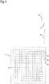
- Figure 1 schematically shows an embodiment of the flexible surface element 1 according to the invention.
- the flexible surface element 1 is formed by a textile surface element.
- the textile surface element can be, for example, a woven fabric, knitted fabric, knitted fabric, embroidery or a fleece.
- the flexible surface element can be formed from a film.
- a sensor structure is incorporated into the flexible surface element 1, which forms an electrically conductive structure.
- the sensor structure generally serves to detect mechanical interventions in the flexible surface element 1, in particular in the form of punctures in the flexible surface element 1. These interventions generally change the electrical properties of the sensor structure. These changes define a detection variable on the basis of which the intervention can be detected.
- the sensor structure consists of a lattice structure made of electrically conductive threads 2, which can consist of metallic and / or non-metallic materials.
- a periodic lattice structure is provided, which extends essentially over the entire surface of the flexible surface element 1.
- the term lattice structure in the sense of the present invention is to be understood in such a way that the electrically conductive thread (s) form a continuous, preferably loop-shaped structure that extends over the entire flexible surface element.
- This change in resistance is converted into a voltage signal, which is fed to an evaluation unit 3, which can be formed by a microprocessor or the like.
- the electrically conductive threads are particularly advantageously made of low-resistance materials.
- the electrically conductive threads then generate low-voltage signals that can be fed directly to the evaluation unit.
- a signal is generated in the evaluation unit 3 from the sensor signals formed in this way, the signal states of which in particular indicate whether there is an engagement in the flexible surface element 1 or not.
- an alarm signal is generated in the evaluation unit 3 when there is an intervention in the flexible surface element 1.
- the evaluation unit 3 can be fixed on the flexible surface element 1 by a welded or adhesive connection.
- the evaluation unit can have a fuse or the like as protection against manipulation. If the housing of the evaluation unit is opened without authorization, the fuse responds and the evaluation unit generates a manipulation alarm signal.
- an autonomous energy supply in the form of a battery 4 and a radio transmitter 5 are also arranged on the flexible surface element 1, and these units can also be fixed on the flexible surface element 1 by means of adhesive or welded connections.
- the evaluation unit 3 and the radio transmitter 5 are interconnected and are connected to the battery 4. These units are supplied with voltage by the battery 4.
- Signals generated in the evaluation unit 3 are transmitted via the radio transmitter 5 as radio signals 6 to a radio receiver 7 which is assigned to an external unit.
- the radio receiver 7 can be integrated in the external unit.
- the external unit is formed by a reporting unit 8.
- the reporting unit 8 has optical and / or acoustic signal transmitters. With these signal transmitters, an alarm signal that is reported by the evaluation unit 3 can be displayed. Furthermore, the reporting unit 8 can be connected, for example via an Internet connection, to further external units to which the signals, in particular alarm signals from the evaluation unit 3 of the flexible surface element 1, are fed.
- the external unit can generally also be formed by a smartphone.
- the assigned radio receiver 7 has a SIM card or a Sigfox module for coupling to the smartphone.
- the external unit can also have a simple power supply.
- the external unit like the evaluation unit, can have tamper protection.
- the radio transmitter 5 of the flexible surface element 1 and the radio receiver 7 of the external unit form a unidirectional radio transmission link.
- a bidirectional radio transmission link is also possible.
- both the flexible surface element 1 and the external unit have a radio transmitter 5 and a radio receiver 7.
- radio signals 6 in the MHz range are transmitted via the radio transmission link, particularly advantageously at a frequency of 868 MHz.
- Bluetooth radio transmission links can be used.
- FIG 2 shows an application example of the arrangement according to Figure 1 .
- the tarpaulin 9 is formed on a trailer 10 of a truck 11 by the flexible surface element 1 according to the invention.
- the reporting unit 8 with the radio receiver 7, which receives the signals of the radio transmitter 5 on the flexible surface element 1, is located in the driver's cab 12 of the truck 11.
- the reporting unit 8 can also be arranged in the area of the trailer 10.
- the invention can be used for vehicles of all types, in particular also for rail-bound vehicles.
Landscapes
- Engineering & Computer Science (AREA)
- Mechanical Engineering (AREA)
- Textile Engineering (AREA)
- Chemical & Material Sciences (AREA)
- Inorganic Chemistry (AREA)
- Physics & Mathematics (AREA)
- General Physics & Mathematics (AREA)
- Alarm Systems (AREA)
- Burglar Alarm Systems (AREA)
- Professional, Industrial, Or Sporting Protective Garments (AREA)
Abstract
Description
- Die Erfindung betrifft ein flexibles Flächenelement gemäß dem Oberbegriff des Anspruchs 1.
- Ein derartiges flexibles Flächenelement weist allgemein eine Sensorstruktur mit einer Auswerteeinheit auf, die dazu ausgebildet sind, Einschnitte in das flexible Flächenelement zu detektieren. Damit können diese Flächenelemente dazu verwendet werden, einen Schutz gegen Einbruch, Diebstahl, Vandalismus zu gewährleisten. Generell wird dadurch ein Schutz des flexiblen Flächenelements gegen unbefugte Eingriffe gewährleistet. Dementsprechend können mit dem flexiblen Flächenelement umhüllte Objekte gegen unbefugte Eingriffe geschützt werden.
- Ein derartiges flexibles Flächenelement ist aus der
WO 2018/113993 bekannt. Das dort beschriebene flexible Flächenelement umfasst Sensorstrukturen und Schnittfeststrukturen, die mittels einer Kettenwirkmaschine oder Raschelmaschine als Sensorfäden beziehungsweise schnittfeste Fäden als Schnittfeststruktur in das flexible Flächenelement eingearbeitet werden. - Mit der Schnittfeststruktur wird generell ein mechanischer Schutz gegen ein Durchstoßen des Flächenelements mit Gegenständen wie Messern oder ähnlich scharfkantigen Objekten erzielt. Die Schnittfeststrukturen sind dabei so ausgebildet, dass allenfalls nur ein lokales Einstechen in das Flächenelement möglich ist, nicht jedoch ein großflächiges Auftrennen des Flächenelements. Weiterhin wird ein Durchstoßen des Flächenelements mit der Sensorstruktur erfasst, so dass dann beispielsweise ein Alarmsignal generiert wird, das den unbefugten Eingriff auf das Flächenelement meldet.
- Der Erfindung liegt die Aufgabe zugrunde, ein flexibles Flächenelement der eingangs genannten Art bereitzustellen, welches flexibel einsetzbar ist und eine hohe Funktionalität aufweist.
- Zur Lösung dieser Aufgabe sind die Merkmale des Anspruchs 1 vorgesehen. Vorteilhafte Ausführungsformen und zweckmäßige Weiterbildungen der Erfindung sind in den abhängigen Ansprüchen beschrieben.
- Die Erfindung betrifft ein flexibles Flächenelement mit einer Sensorstruktur und einer zugeordneten Auswerteeinheit, welche ausgebildet sind, Einschnitte in dem flexiblen Flächenelement zu detektieren. An dem flexiblen Flächenelement sind eine autarke Energieversorgung und ein Funksender vorgesehen, welche an die Auswerteeinheit angeschlossen sind. In der Auswerteeinheit generierte Signale sind mittels des Funksenders an einen Funkempfänger einer externen Einheit übertragbar.
- Mit der Sensorstruktur wird ein wirksamer Manipulationsschutz derart erhalten, dass ein Durchstoßen des flexiblen Flächenelements sicher detektiert werden kann. Dabei kann ein Durchstoßen an einer beliebigen Stelle des flexiblen Flächenelements erkannt werden, wodurch ein vollständiger, umfassender Manipulationsschutz erzielt wird.
- Erfindungsgemäß ist nicht nur die Sensorstruktur in das flexible Flächenelement eingearbeitet. Auch eine Auswerteeinheit, die in Form eines Mikroprozessors oder dergleichen ausgebildet sein kann, ist auf dem flexiblen Flächenelement angeordnet. Mit dieser erfolgt auf dem flexiblen Flächenelement selbst eine Auswertung von Sensorsignalen. In Abhängigkeit dieser Auswertung generiert die Auswerteeinheit Signale, die insbesondere angeben, ob ein Defekt in der Sensorstruktur vorliegt oder nicht, das heißt mit den Signalen wird angezeigt, ob eine Unterbrechung der Sensorstruktur vorliegt oder nicht. Insbesondere wird in der Auswerteeinheit ein Alarmsignal generiert, wenn ein Durchstoßen der Sensorstruktur detektiert wird.
- Ein wesentlicher Aspekt der Erfindung besteht darin, dass auf dem flexiblen Flächenelement weiterhin ein Funksender und eine autarke Energieversorgung vorgesehen sind.
- Der Grundgedanke der Erfindung besteht darin, dass die Signale der Auswerteeinheit mittels des Funksenders an einen Funkempfänger einer externen Einheit gesendet werden. Da mit dem Funksender und dem Funkempfänger eine berührungslose Funkübertragungsstrecke gebildet wird, über welche auch über große Entfernungen Daten gesendet werden können, kann der Ort der externen Einheit völlig unabhängig vom Installationsort des flexiblen Flächenelements gewählt werden, wodurch eine hohe Bedienerfreundlichkeit erzielt wird.
- Mit dem flexiblen Flächenelement kann damit an einem Installationsort eine Umhüllung von Objekten erfolgen, wodurch diese Objekte gegen unbefugte Eingriffe geschützt sind. Die Objekte können dabei unterschiedliche Formen und Geometrien aufweisen, da die Größe des flexiblen Flächenelements flexibel an die jeweilige Applikation angepasst werden kann.
- Ein weiterer wesentlicher Aspekt der Erfindung besteht darin, dass das flexible Flächenelement mit der Sensorstruktur und den dieser zugeordneten Komponenten, nämlich der Auswerteeinheit und dem Funksender, eine einfache, wartungsfreie Einheit ausbildet. Dies wird erfindungsgemäß dadurch erreicht, dass der Sensorstruktur, der Auswerteeinheit und dem Funksender auf dem flexiblen Flächenelement eine autarke Energieversorgung zugeordnet ist, welche vorteilhaft von einer Batterie gebildet ist. Mit der autarken Energieversorgung wird über einen großen Zeitraum eine zuverlässige Spannungsversorgung für die elektrischen Komponenten auf dem flexiblen Flächenelement bereitgestellt, so dass diese entsprechend wartungsfrei und unabhängig von stationären Spannungsversorgungen betrieben werden können. Besonders vorteilhaft stellt die autarke Energieversorgung eine Spannungsversorgung für die gesamte zu erwartende Lebensdauer der elektronischen Komponenten und auch des flexiblen Flächenelements zur Verfügung.
- Die autarke Energieversorgung weist wie auch die Auswerteeinheit eine sehr kleine Bauform auf, so dass diese Einheiten platzsparend auf dem flexiblen Flächenelement angeordnet werden können, wobei die Fixierung beispielsweise durch Schweiß- oder Klebeverbindungen erfolgt.
- Besonders vorteilhaft ist das flexible Flächenelement ein textiles Flächenelement.
- Insbesondere kann das textile Flächenelement ein Gestrick, ein Gewirke, ein Gewebe, eine Stickerei oder ein Vlies sein. Prinzipiell kann das flexible Flächenelement von einer Folie, insbesondere auch von einer beschichteten Folie gebildet sein.
- Generell kann das flexible Flächenelement auch nur teilweise aus textilen Materialien bestehen. Beispielsweise können textile Flächenelemente mit Folien oder dergleichen Verbundstrukturen bilden.
- Durch eine geeignete Wahl der Materialbeschaffenheit der Fäden, aus welchen das textile Flächenelement besteht, kann eine Anpassung an die jeweilige Applikation erfolgen. Insbesondere kann so das textile Flächenelement für einen Outdoor-Einsatz ausgebildet sein.
- Gemäß einer vorteilhaften Ausführungsform ist die Sensorstruktur von elektrisch leitfähigen Fäden gebildet, welche in das Flächenelement eingearbeitet sind.
- Vorteilhaft bestehen die elektrisch leitfähigen Fäden aus einem metallischen Werkstoff.
- Generell können die elektrisch leitfähigen Fäden auch aus nicht metallischen Werkstoffen bestehen.
- Die elektrisch leitfähigen Fäden können vorteilhaft mit geeigneten Textilmaschinen wie zum Beispiel Kettenwirkmaschinen in das textile Flächenelement eingearbeitet werden, das heißt die elektrisch leitfähigen Fäden können in automatisierten Prozessen rationell im textilen Flächenelement eingearbeitet werden.
- Besonders vorteilhaft bilden die elektrisch leitfähigen Fäden eine Gitterstruktur aus, welche sich über das gesamte Flächenelement erstreckt. Eine Gitterstruktur im Sinne der vorliegenden Anmeldung ist dabei derart ausgebildet, dass sich ein durchgehender elektrisch leitfähiger Faden schlaufenförmig über die gesamte Fläche des Flächenelements erstreckt.
- Die Detektion eines Eingriffs in das flexible Flächenelement kann durch eine Widerstandsänderung, die durch ein lokales Unterbrechen der Gitterstruktur der elektrisch leitfähigen Fäden oder allgemein in die Sensorstruktur bewirkt wird. Die Auswerteeinheit weist hierzu Mittel auf, diese Widerstandsänderung als Sensorsignal der Sensorstruktur zu erfassen. Beispielsweise kann die Gitterstruktur der elektrisch leitfähigen Fäden oder allgemein die Sensorstruktur an ein Messnetzwerk, insbesondere an Messwiderstände angeschlossen werden, deren Widerstandsänderung in die Auswerteeinheit, beispielsweise in Form eines Spannungssignals, eingelesen wird.
- Besonders vorteilhaft bestehen die elektrisch leitfähigen Fäden aus niederohmigen Werkstoffen. Derartige elektrisch leitfähige Fäden generieren Niederspannungssignale, die in der Auswerteeinheit unmittelbar ausgewertet werden können, so dass keine zusätzlichen Schaltungen zur Umsetzung der in den elektrisch leitfähigen Fäden generierten Signale mehr notwendig sind. Besonders vorteilhaft generieren die elektrisch leitfähigen Fäden binäre Niederspannungssignale in Abhängigkeit davon, ob eine Unterbrechung der elektrisch leitfähigen Fäden vorliegt oder nicht.
- Abhängig von diesen Sensorsignalen generiert die Auswerteeinheit Signale, die über den Funksender ausgesendet und in der externen Einheit zugeführt werden. Insbesondere generiert die Auswerteeinheit ein Alarmsignal, wenn mit der Sensorstruktur ein Eingriff in die Sensorstruktur detektiert wird.
- Besonders vorteilhaft ist im Gehäuse der Auswerteeinheit eine Sicherung oder ein sonstiges Sensorelement vorgesehen, welche beziehungsweise welches bei einem unerlaubten Öffnen des Gehäuses anspricht. Bei einem solchen Ansprechen generiert die Auswerteeinheit ein Manipulations-Alarmsignal.
- Weiterhin kann die Auswerteeinheit auch Signale generieren, die Statusmeldungen beinhalten, die an die externe Einheit ausgegeben werden, wodurch die Funktionsfähigkeit der Sensorstruktur und der Auswerteeinheit überprüft werden kann.
- Besonders vorteilhaft sind der Funksender und der Funkempfänger Bestandteil einer bidirektionalen Funkübertragungsstrecke.
- Dies kann dadurch realisiert werden, indem sowohl auf dem flexiblen Flächenelement als auch in oder an der externen Einheit jeweils ein Funksender und Funkempfänger vorgesehen sind. In diesem Fall können auch an der externen Einheit Signale in die Auswerteeinheit eingelesen werden, beispielsweise um eine Parametrierung durchzuführen.
- Gemäß einer besonders vorteilhaften Ausgestaltung bilden der Funksender und der Funkempfänger eine Funkübertragungsstrecke, bei welcher Funksignale im MHz-Bereich übertragen werden.
- Geeignete Frequenzen, auf welche Signale übertragen werden können, liegen im Bereich von 800 MHz.
- Gemäß einer alternativen Ausgestaltung bilden der Funksender und der Funkempfänger eine Bluetooth-Funkübertragungsstrecke aus. In diesem Fall werden Signale in anderen Frequenzbereichen.
- Gemäß einer vorteilhaften Ausführungsform bildet die externe Einheit eine Meldeeinheit aus.
- Die Meldeeinheit kann eine mobile Einheit sein. Weiterhin kann die Meldeeinheit eine stationäre Einheit bilden, die relativ zum flexiblen Flächenelement in einer vorgegebenen Distanz platziert wird, die innerhalb der Reichweite der vom Funksender und Funkempfänger gebildeten Funkübertragungsstrecke liegt.
- Die Meldeeinheit weist generell optische oder akustische Signalgeber auf, die ein Alarmsignal anzeigen, wenn ein Eingriff in das flexible Flächenelement gegeben ist. Weiterhin kann die Meldeeinheit auch ein I/0 Modul, beispielsweise mit einem Bildschirm und einer Tastatur zur Ein- und Ausgabe von Daten aufweisen.
- Prinzipiell ist es auch möglich, die Meldeeinheit über das Internet an weitere Stationen anzukoppeln, so dass von diesen Stationen an beliebigen Standorten eine Manipulationskontrolle des flexiblen Flächenelements möglich ist.
- Gemäß einer alternativen Ausgestaltung ist die externe Einheit ein Smartphone.
- Zur Ankopplung an dieses Smartphone weist dann der Funkempfänger bevorzugt eine SIM-Karte oder ein Sigfox-Modul auf.
- In der Auswerteeinheit generierte Signale, insbesondere Alarmsignale oder Manipulations-Alarmsignale, können dann als Nachrichten auf dem Smartphone angezeigt werden.
- Das erfindungsgemäße flexible Flächenelement kann für unterschiedliche Applikationen eingesetzt werden.
- Beispielsweise können mit derartigen flexiblen Flächenelementen Koffer, Taschen, Rucksäcke oder dergleichen hergestellt werden. Die dort gelagerten Objekte sind durch die Sensorstruktur effizient gegen Manipulationen wie Diebstahl, Vandalismus und dergleichen gesichert.
- Gemäß einer besonders vorteilhaften Anwendung bildet das flexible Flächenelement eine Plane aus. Beispielsweise ist die Plane an einer Ladefläche eines Fahrzeugs oder eines Anhängers eines Fahrzeugs angebracht.
- In diesem Fall kann beispielsweise in der Fahrerkabine eine Meldeeinheit mit dem Funkempfänger integriert sein. So kann der Fahrer des Fahrzeugs einfach und schnell Manipulationsversuche an der Plane feststellen.
- Die Erfindung wird im Folgenden anhand der Zeichnungen erläutert. Es zeigen:
-
Figur 1 : Ausführungsbeispiel des erfindungsgemäßen flexiblen Flächenelements mit einer zugeordneten Meldeeinheit. -
Figur 2 : Applikationsbeispiel für die Anordnung gemäßFigur 1 . -
Figur 1 zeigt schematisch ein Ausführungsbeispiel des erfindungsgemäßen flexiblen Flächenelements 1. - Das flexible Flächenelement 1 ist im vorliegenden Fall von einem textilen Flächenelement gebildet. Das textile Flächenelement kann zum Beispiel ein Gewebe, Gestrick, Gewirke, eine Stickerei oder ein Vlies sein. Weiterhin kann das flexible Flächenelement aus einer Folie gebildet sein.
- Erfindungsgemäß ist in das flexible Flächenelement 1 eine Sensorstruktur eingearbeitet, die eine elektrisch leitfähige Struktur ausbildet. Die Sensorstruktur dient allgemein zur Detektion von mechanischen Eingriffen in das flexible Flächenelement 1, insbesondere in Form von Einstichen in das flexible Flächenelement 1. Diese Eingriffe ändern generell die elektrischen Eigenschaften der Sensorstruktur. Diese Änderungen definieren eine Detektionsgröße anhand derer der Eingriff detektiert werden kann.
- Im vorliegenden Fall besteht die Sensorstruktur aus einer Gitterstruktur aus elektrisch leitfähigen Fäden 2, die aus metallischen und/oder nicht metallischen Werkstoffen bestehen können. Im vorliegenden Fall ist eine periodische Gitterstruktur vorgesehen, die sich im Wesentlichen über die gesamte Fläche des flexiblen Flächenelements 1 erstreckt. Der Begriff Gitterstruktur im Sinne der vorliegenden Erfindung ist so zu verstehen, dass der oder die elektrisch leitfähigen Fäden eine durchgehende vorzugsweise schlaufenförmige Struktur ausbilden, die sich über das gesamte flexible Flächenelement erstreckt.
- Dies führt zu einer Widerstandsänderung der Gitterstruktur, die beispielsweise in einem Messnetzwerk erfasst wird.
- Diese Widerstandsänderung wird in ein Spannungssignal umgesetzt, das einer Auswerteeinheit 3 zugeführt ist, die von einem Mikroprozessor oder dergleichen gebildet sein kann.
- Besonders vorteilhaft bestehen die elektrisch leitfähigen Fäden aus niederohmigen Materialien. Dann generieren die elektrisch leitfähigen Fäden Niederspannungssignale, die der Auswerteeinheit direkt zugeführt werden können.
- In der Auswerteeinheit 3 wird aus den so gebildeten Sensorsignalen ein Signal generiert, dessen Signalzustände insbesondere angeben, ob ein Eingriff im flexiblen Flächenelement 1 vorliegt oder nicht. Insbesondere wird in der Auswerteeinheit 3 ein Alarmsignal generiert, wenn ein Eingriff im flexiblen Flächenelement 1 vorliegt. Die Auswerteeinheit 3 kann durch eine Schweiß- oder Klebeverbindung auf dem flexiblen Flächenelement 1 fixiert sein.
- Die Auswerteeinheit kann eine Sicherung oder dergleichen als Manipulationsschutz aufweisen. Wird das Gehäuse der Auswerteeinheit unbefugt geöffnet, spricht die Sicherung an und die Auswerteeinheit generiert ein Manipulations-Alarmsignal.
- Erfindungsgemäß sind auf dem flexiblen Flächenelement 1 weiterhin eine autarke Energieversorgung in Form einer Batterie 4 und ein Funksender 5 angeordnet, wobei auch diese Einheiten mittels Klebe- oder Schweißverbindungen auf dem flexiblen Flächenelement 1 fixiert sein können.
- Die Auswerteeinheit 3 und der Funksender 5 sind untereinander verbunden und werden an die Batterie 4 angeschlossen. Mit der Batterie 4 erfolgt eine Spannungsversorgung dieser Einheiten.
- In der Auswerteeinheit 3 generierte Signale werden über den Funksender 5 als Funksignale 6 an einen Funkempfänger 7 übertragen, der einer externen Einheit zugeordnet ist. Insbesondere kann der Funkempfänger 7 in der externen Einheit integriert sein.
- Im vorliegenden Fall ist die externe Einheit von einer Meldeeinheit 8 gebildet. Die Meldeeinheit 8 weist optische und/oder akustische Signalgeber auf. Mit diesen Signalgebern kann ein Alarmsignal, das von der Auswerteeinheit 3 gemeldet wird, angezeigt werden. Weiterhin kann die Meldeeinheit 8 zum Beispiel über eine Internetverbindung mit weiteren externen Einheiten verbunden sein, denen die Signale, insbesondere Alarmsignale der Auswerteeinheit 3 des flexiblen Flächenelements 1, zugeführt werden.
- Die externe Einheit kann generell auch von einem Smartphone gebildet sein. In diesem Fall weist der zugeordnete Funkempfänger 7 eine SIM-Karte oder ein Sigfox-Modul zur Ankopplung an das Smartphone auf. Auch die externe Einheit kann eine einfache Energieversorgung aufweisen. Zudem kann die externe Einheit wie die Auswerteeinheit einen Manipulationsschutz aufweisen.
- Im vorliegenden Fall bilden der Funksender 5 des flexiblen Flächenelements 1 und der Funkempfänger 7 der externen Einheit eine unidirektionale Funkübertragungsstrecke. Prinzipiell ist auch eine bidirektionale Funkübertragungsstrecke möglich. Dann weisen sowohl das flexible Flächenelement 1 als auch die externe Einheit einen Funksender 5 und einen Funkempfänger 7 auf.
- Im vorliegenden Fall werden über die Funkübertragungsstrecke Funksignale 6 im MHz-Bereich übertragen, besonders vorteilhaft bei einer Frequenz von 868 MHz. Alternativ können Bluetooth-Funkübertragungsstrecken eingesetzt werden.
-
Figur 2 zeigt ein Applikationsbeispiel der Anordnung gemäßFigur 1 . In diesem Fall ist die Plane 9 auf einem Anhänger 10 eines Lastkraftwagens 11 von dem erfindungsmäßigen flexiblen Flächenelement 1 gebildet. In dem Fahrerhaus 12 des Lastkraftwagens 11 befindet sich die Meldeeinheit 8 mit dem Funkempfänger 7, der die Signale des Funksenders 5 auf dem flexiblen Flächenelement 1 empfängt. Die Meldeeinheit 8 kann auch im Bereich des Anhängers 10 angeordnet sein. - Generell ist die Erfindung für Fahrzeuge aller Art anwendbar, insbesondere auch für schienengebundene Fahrzeuge.
-
- (1) Flexibles Flächenelement
- (2) Elektrisch leitfähiger Faden
- (3) Auswerteeinheit
- (4) Batterie
- (5) Funksender
- (6) Funksignal
- (7) Funkempfänger
- (8) Meldeeinheit
- (9) Plane
- (10) Anhänger
- (11) Lastkraftwagen
- (12) Fahrerhaus
Claims (15)
- Flexibles Flächenelement (1) mit einer Sensorstruktur und einer zugeordneten Auswerteeinheit (3), welche ausgebildet sind, Einschnitte in dem flexiblen Flächenelement (1) zu detektieren, dadurch gekennzeichnet, dass an dem flexiblen Flächenelement (1) eine autarke Energieversorgung und ein Funksender (5) vorgesehen sind, welche an die Auswerteeinheit (3) angeschlossen sind, wobei in der Auswerteeinheit (3) generierte Signale mittels des Funksenders (5) an einen Funkempfänger (7) einer externen Einheit übertragbar sind.
- Flexibles Flächenelement (1) nach Anspruch 1, dadurch gekennzeichnet, dass dieses ein textiles Flächenelement ist.
- Flexibles Flächenelement (1) nach Anspruch 2, dadurch gekennzeichnet, dass das textile Flächenelement ein Gestrick, ein Gewirke, eine Stickerei, ein Gewebe oder ein Vlies ist.
- Flexibles Flächenelement (1) nach Anspruch 1 - 3, dadurch gekennzeichnet, dass die Sensorstruktur von elektrisch leitfähigen Fäden (2) gebildet ist, welche in das Flächenelement eingearbeitet sind, wobei insbesondere die elektrisch leitfähigen Fäden (2) aus einem metallischen Werkstoff bestehen, und insbesondere die elektrisch leitfähigen Fäden (2) eine Gitterstruktur ausbilden, welche sich über das gesamte Flächenelement erstreckt.
- Flexibles Flächenelement (1) nach Anspruch 4, dadurch gekennzeichnet, dass die elektrisch leitfähigen Fäden (2) aus niederohmigen Werkstoffen bestehen, und/oder dass die elektrisch leitfähigen Fäden (2) abhängig davon, ob diese unterbrochen sind oder nicht, Niederspannungssignale generieren, die in der Auswerteeinheit (3) unmittelbar ausgewertet werden können.
- Flexibles Flächenelement (1) nach einem der Ansprüche 1 - 5, dadurch gekennzeichnet, dass die Auswerteeinheit (3) ein Alarmsignal generiert, wenn mit der Sensorstruktur ein Eingriff in die Sensorstruktur detektiert wird.
- Flexibles Flächenelement (1) nach einem der Ansprüche 1 - 6, dadurch gekennzeichnet, dass die Auswerteeinheit (3) einen Manipulationsschutz aufweist.
- Flexibles Flächenelement (1) nach einem der Ansprüche 1 - 7, dadurch gekennzeichnet, dass die autarke Energieversorgung eine Batterie (4) ist.
- Flexibles Flächenelement (1) nach einem der Ansprüche 1 - 8, dadurch gekennzeichnet, dass der Funksender (5) und der Funkempfänger (7) eine Funkübertragungsstrecke bilden, bei welcher Funksignale (6) im MHz-Bereich übertragen werden.
- Flexibles Flächenelement (1) nach einem der Ansprüche 1 - 9, dadurch gekennzeichnet, dass der Funksender (5) und der Funkempfänger (7) eine Bluetooth-Funkübertragungsstrecke ausbilden, und/oder dass der Funksender (5) und der Funkempfänger (7) Bestandteil einer bidirektionalen Funkübertragungsstrecke sind.
- Flexibles Flächenelement (1) nach einem der Ansprüche 1 - 10, dadurch gekennzeichnet, dass die externe Einheit eine Meldeeinheit (8) ausbildet, oder ein Smartphone ist.
- Flexibles Flächenelement (1) nach Anspruch 11, dadurch gekennzeichnet, dass zur Verbindung mit dem Smartphone der Funkempfänger (7) eine SIM-Karte oder ein Sigfox-Modul aufweist.
- Flexibles Flächenelement (1) nach einem der Ansprüche 1 - 12, dadurch gekennzeichnet, dass dieses eine Plane (9) ausbildet.
- Flexibles Flächenelement (1) nach Anspruch 13, dadurch gekennzeichnet, dass die Plane (9) an einer Ladefläche eines Fahrzeugs oder eines Anhängers (10) eines Fahrzeugs angebracht ist.
- Flexibles Flächenelement (1) nach Anspruch 14, dadurch gekennzeichnet, dass der dem an der Plane (9) angeordneten Funksender (5) zugeordnete Funkempfänger (7) am Fahrzeug oder am Anhänger (10) angeordnet ist.
Applications Claiming Priority (2)
| Application Number | Priority Date | Filing Date | Title |
|---|---|---|---|
| DE202019100517 | 2019-01-29 | ||
| DE202019100689.7U DE202019100689U1 (de) | 2019-01-29 | 2019-02-06 | Flexibles Flächenelement |
Publications (3)
| Publication Number | Publication Date |
|---|---|
| EP3690837A1 true EP3690837A1 (de) | 2020-08-05 |
| EP3690837B1 EP3690837B1 (de) | 2024-06-12 |
| EP3690837B8 EP3690837B8 (de) | 2024-07-24 |
Family
ID=70776650
Family Applications (1)
| Application Number | Title | Priority Date | Filing Date |
|---|---|---|---|
| EP20152096.2A Active EP3690837B8 (de) | 2019-01-29 | 2020-01-16 | Flexibles flächenelement mit sensorstruktur aus elektrischen leitern |
Country Status (2)
| Country | Link |
|---|---|
| EP (1) | EP3690837B8 (de) |
| DE (1) | DE202019100689U1 (de) |
Cited By (1)
| Publication number | Priority date | Publication date | Assignee | Title |
|---|---|---|---|---|
| EP4092641B1 (de) * | 2021-05-20 | 2024-08-21 | Schmitz Cargobull AG | Kofferaufbau für ein nutzfahrzeug und verfahren zur herstellung eines flächenelements für einen solchen kofferaufbau |
Citations (4)
| Publication number | Priority date | Publication date | Assignee | Title |
|---|---|---|---|---|
| US5686909A (en) * | 1996-06-05 | 1997-11-11 | Steinhauser; Louis P. | Alarm system for boat covers and automobile convertible tops |
| WO2009018591A1 (en) * | 2007-07-27 | 2009-02-05 | Thomas Francis Greyling | Luggage protective device |
| DE102015120783A1 (de) * | 2015-11-30 | 2017-06-01 | Harald Katschke | Verpackungssystem |
| WO2018113993A1 (de) | 2016-12-23 | 2018-06-28 | Go11Save Ag | Verfahren zur herstellung von sicherheitsstrukturen bei einem flächenelement und flächenelement |
Family Cites Families (3)
| Publication number | Priority date | Publication date | Assignee | Title |
|---|---|---|---|---|
| EP1815563A4 (de) * | 2004-11-02 | 2009-12-02 | Hi G Tek Inc | Aus der ferne überwachbare elektronische verriegelungseinrichtung |
| BE1019831A3 (nl) * | 2011-02-18 | 2013-01-08 | Sioen Ind | Dekzeil met beveiliging. |
| EP3494557B1 (de) * | 2016-10-18 | 2020-04-22 | Relytex GmbH & Co. KG | Sicherungssystem |
-
2019
- 2019-02-06 DE DE202019100689.7U patent/DE202019100689U1/de not_active Expired - Lifetime
-
2020
- 2020-01-16 EP EP20152096.2A patent/EP3690837B8/de active Active
Patent Citations (4)
| Publication number | Priority date | Publication date | Assignee | Title |
|---|---|---|---|---|
| US5686909A (en) * | 1996-06-05 | 1997-11-11 | Steinhauser; Louis P. | Alarm system for boat covers and automobile convertible tops |
| WO2009018591A1 (en) * | 2007-07-27 | 2009-02-05 | Thomas Francis Greyling | Luggage protective device |
| DE102015120783A1 (de) * | 2015-11-30 | 2017-06-01 | Harald Katschke | Verpackungssystem |
| WO2018113993A1 (de) | 2016-12-23 | 2018-06-28 | Go11Save Ag | Verfahren zur herstellung von sicherheitsstrukturen bei einem flächenelement und flächenelement |
Cited By (1)
| Publication number | Priority date | Publication date | Assignee | Title |
|---|---|---|---|---|
| EP4092641B1 (de) * | 2021-05-20 | 2024-08-21 | Schmitz Cargobull AG | Kofferaufbau für ein nutzfahrzeug und verfahren zur herstellung eines flächenelements für einen solchen kofferaufbau |
Also Published As
| Publication number | Publication date |
|---|---|
| EP3690837B8 (de) | 2024-07-24 |
| EP3690837B1 (de) | 2024-06-12 |
| DE202019100689U1 (de) | 2020-04-30 |
Similar Documents
| Publication | Publication Date | Title |
|---|---|---|
| DE19919158C2 (de) | Drahtloses Schalterdetektionssystem | |
| EP2080180B1 (de) | Annäherungsnachweissystem zum nachweis einer annäherung einer person an ein objekt, insbesondere an eine maschine | |
| DE102008008072A1 (de) | Sensor | |
| EP2709081B1 (de) | Verfahren zur Überwachung der Funktionsfähigkeit eines RFID- gestützten Funkkommunikationsnetzes in einem räumlich ausgedehnten Gebiet | |
| DE10305342A1 (de) | System und Verfahren zur Absicherung von Gefährdungsbereichen | |
| DE102014113832A1 (de) | Daten- und Messerfassungsvorrichtung für einen Türgriff sowie Verfahren dazu | |
| DE112017005187T5 (de) | Sicherheitsgurtstatus-Überwachungssystem | |
| DE2226742C3 (de) | Kontrollvorrichtung zur Überwachung des Gebrauchs eines Sicherheitsgurtes | |
| EP3690837A1 (de) | Flexibles flächenelement mit sensorstruktur aus elektrischen leitern | |
| DE102017121823A1 (de) | Funkschlüssel für Kraftfahrzeuge | |
| DE102007018423B4 (de) | Vorrichtung mit einem Gefahrenbereich und Verfahren zu ihrem Betrieb | |
| DE10140930C1 (de) | Taktiles Sensorsystem mit Transponder | |
| EP3712866A1 (de) | Flexibles flächenelement | |
| EP3617009B1 (de) | System und verfahren zur erkennung des verriegelungs- und/oder funktionszustandes eines sicherheitsgurtsystems | |
| WO2022007993A1 (de) | Gurtriss-überwachungssystem | |
| EP3494557B1 (de) | Sicherungssystem | |
| WO2009000870A1 (de) | Elektronische zustandserfassungseinrichtung | |
| DE102010011766B4 (de) | Überwachungseinrichtung | |
| DE4300350A1 (de) | Alarmgeberanordnung | |
| DE3941509C2 (de) | ||
| EP3926776A1 (de) | Spannungswarner, spannungswarnsystem sowie elektrische anlage | |
| WO2014121790A1 (de) | Vorrichtung und verfahren zur feststellung eines betriebsgefährdenden zustandes eines bandförmigen lastträgers | |
| DE102008048107A1 (de) | Flexible Antennendiagnose für integrierte Scheibenantennen am Heizfeld | |
| DE202023107643U1 (de) | Bedieneinheit | |
| DE102022103841A1 (de) | Anordnung von zwei Sicherheitssensoren |
Legal Events
| Date | Code | Title | Description |
|---|---|---|---|
| PUAI | Public reference made under article 153(3) epc to a published international application that has entered the european phase |
Free format text: ORIGINAL CODE: 0009012 |
|
| STAA | Information on the status of an ep patent application or granted ep patent |
Free format text: STATUS: THE APPLICATION HAS BEEN PUBLISHED |
|
| AK | Designated contracting states |
Kind code of ref document: A1 Designated state(s): AL AT BE BG CH CY CZ DE DK EE ES FI FR GB GR HR HU IE IS IT LI LT LU LV MC MK MT NL NO PL PT RO RS SE SI SK SM TR |
|
| AX | Request for extension of the european patent |
Extension state: BA ME |
|
| STAA | Information on the status of an ep patent application or granted ep patent |
Free format text: STATUS: REQUEST FOR EXAMINATION WAS MADE |
|
| 17P | Request for examination filed |
Effective date: 20200805 |
|
| RBV | Designated contracting states (corrected) |
Designated state(s): AL AT BE BG CH CY CZ DE DK EE ES FI FR GB GR HR HU IE IS IT LI LT LU LV MC MK MT NL NO PL PT RO RS SE SI SK SM TR |
|
| STAA | Information on the status of an ep patent application or granted ep patent |
Free format text: STATUS: EXAMINATION IS IN PROGRESS |
|
| 17Q | First examination report despatched |
Effective date: 20220316 |
|
| GRAP | Despatch of communication of intention to grant a patent |
Free format text: ORIGINAL CODE: EPIDOSNIGR1 |
|
| STAA | Information on the status of an ep patent application or granted ep patent |
Free format text: STATUS: GRANT OF PATENT IS INTENDED |
|
| INTG | Intention to grant announced |
Effective date: 20240104 |
|
| GRAS | Grant fee paid |
Free format text: ORIGINAL CODE: EPIDOSNIGR3 |
|
| GRAA | (expected) grant |
Free format text: ORIGINAL CODE: 0009210 |
|
| STAA | Information on the status of an ep patent application or granted ep patent |
Free format text: STATUS: THE PATENT HAS BEEN GRANTED |
|
| AK | Designated contracting states |
Kind code of ref document: B1 Designated state(s): AL AT BE BG CH CY CZ DE DK EE ES FI FR GB GR HR HU IE IS IT LI LT LU LV MC MK MT NL NO PL PT RO RS SE SI SK SM TR |
|
| REG | Reference to a national code |
Ref country code: GB Ref legal event code: FG4D Free format text: NOT ENGLISH |
|
| REG | Reference to a national code |
Ref country code: CH Ref legal event code: EP |
|
| REG | Reference to a national code |
Ref country code: DE Ref legal event code: R081 Ref document number: 502020008241 Country of ref document: DE Owner name: STEELE, KEVIN ROBERT, SK Free format text: FORMER OWNER: RELYTEX GMBH & CO. KG, 84030 LANDSHUT, DE Ref country code: DE Ref legal event code: R081 Ref document number: 502020008241 Country of ref document: DE Owner name: FINK, HELMUT, AT Free format text: FORMER OWNER: RELYTEX GMBH & CO. KG, 84030 LANDSHUT, DE |
|
| P01 | Opt-out of the competence of the unified patent court (upc) registered |
Effective date: 20240517 |
|
| REG | Reference to a national code |
Ref country code: DE Ref legal event code: R096 Ref document number: 502020008241 Country of ref document: DE |
|
| REG | Reference to a national code |
Ref country code: CH Ref legal event code: PK Free format text: BERICHTIGUNG B8 |
|
| REG | Reference to a national code |
Ref country code: IE Ref legal event code: FG4D Free format text: LANGUAGE OF EP DOCUMENT: GERMAN |
|
| RAP2 | Party data changed (patent owner data changed or rights of a patent transferred) |
Owner name: FINK, HELMUT Owner name: STEELE, KEVIN ROBERT |
|
| PG25 | Lapsed in a contracting state [announced via postgrant information from national office to epo] |
Ref country code: BG Free format text: LAPSE BECAUSE OF FAILURE TO SUBMIT A TRANSLATION OF THE DESCRIPTION OR TO PAY THE FEE WITHIN THE PRESCRIBED TIME-LIMIT Effective date: 20240612 |
|
| PG25 | Lapsed in a contracting state [announced via postgrant information from national office to epo] |
Ref country code: HR Free format text: LAPSE BECAUSE OF FAILURE TO SUBMIT A TRANSLATION OF THE DESCRIPTION OR TO PAY THE FEE WITHIN THE PRESCRIBED TIME-LIMIT Effective date: 20240612 Ref country code: FI Free format text: LAPSE BECAUSE OF FAILURE TO SUBMIT A TRANSLATION OF THE DESCRIPTION OR TO PAY THE FEE WITHIN THE PRESCRIBED TIME-LIMIT Effective date: 20240612 |
|
| REG | Reference to a national code |
Ref country code: LT Ref legal event code: MG9D |
|
| PG25 | Lapsed in a contracting state [announced via postgrant information from national office to epo] |
Ref country code: GR Free format text: LAPSE BECAUSE OF FAILURE TO SUBMIT A TRANSLATION OF THE DESCRIPTION OR TO PAY THE FEE WITHIN THE PRESCRIBED TIME-LIMIT Effective date: 20240913 |
|
| REG | Reference to a national code |
Ref country code: NL Ref legal event code: MP Effective date: 20240612 |
|
| PG25 | Lapsed in a contracting state [announced via postgrant information from national office to epo] |
Ref country code: ES Free format text: LAPSE BECAUSE OF FAILURE TO SUBMIT A TRANSLATION OF THE DESCRIPTION OR TO PAY THE FEE WITHIN THE PRESCRIBED TIME-LIMIT Effective date: 20240612 |
|
| PG25 | Lapsed in a contracting state [announced via postgrant information from national office to epo] |
Ref country code: LV Free format text: LAPSE BECAUSE OF FAILURE TO SUBMIT A TRANSLATION OF THE DESCRIPTION OR TO PAY THE FEE WITHIN THE PRESCRIBED TIME-LIMIT Effective date: 20240612 |
|
| PG25 | Lapsed in a contracting state [announced via postgrant information from national office to epo] |
Ref country code: NO Free format text: LAPSE BECAUSE OF FAILURE TO SUBMIT A TRANSLATION OF THE DESCRIPTION OR TO PAY THE FEE WITHIN THE PRESCRIBED TIME-LIMIT Effective date: 20240912 Ref country code: LV Free format text: LAPSE BECAUSE OF FAILURE TO SUBMIT A TRANSLATION OF THE DESCRIPTION OR TO PAY THE FEE WITHIN THE PRESCRIBED TIME-LIMIT Effective date: 20240612 Ref country code: HR Free format text: LAPSE BECAUSE OF FAILURE TO SUBMIT A TRANSLATION OF THE DESCRIPTION OR TO PAY THE FEE WITHIN THE PRESCRIBED TIME-LIMIT Effective date: 20240612 Ref country code: GR Free format text: LAPSE BECAUSE OF FAILURE TO SUBMIT A TRANSLATION OF THE DESCRIPTION OR TO PAY THE FEE WITHIN THE PRESCRIBED TIME-LIMIT Effective date: 20240913 Ref country code: FI Free format text: LAPSE BECAUSE OF FAILURE TO SUBMIT A TRANSLATION OF THE DESCRIPTION OR TO PAY THE FEE WITHIN THE PRESCRIBED TIME-LIMIT Effective date: 20240612 Ref country code: ES Free format text: LAPSE BECAUSE OF FAILURE TO SUBMIT A TRANSLATION OF THE DESCRIPTION OR TO PAY THE FEE WITHIN THE PRESCRIBED TIME-LIMIT Effective date: 20240612 Ref country code: BG Free format text: LAPSE BECAUSE OF FAILURE TO SUBMIT A TRANSLATION OF THE DESCRIPTION OR TO PAY THE FEE WITHIN THE PRESCRIBED TIME-LIMIT Effective date: 20240612 Ref country code: RS Free format text: LAPSE BECAUSE OF FAILURE TO SUBMIT A TRANSLATION OF THE DESCRIPTION OR TO PAY THE FEE WITHIN THE PRESCRIBED TIME-LIMIT Effective date: 20240912 |
|
| PG25 | Lapsed in a contracting state [announced via postgrant information from national office to epo] |
Ref country code: NL Free format text: LAPSE BECAUSE OF FAILURE TO SUBMIT A TRANSLATION OF THE DESCRIPTION OR TO PAY THE FEE WITHIN THE PRESCRIBED TIME-LIMIT Effective date: 20240612 |
|
| PG25 | Lapsed in a contracting state [announced via postgrant information from national office to epo] |
Ref country code: NL Free format text: LAPSE BECAUSE OF FAILURE TO SUBMIT A TRANSLATION OF THE DESCRIPTION OR TO PAY THE FEE WITHIN THE PRESCRIBED TIME-LIMIT Effective date: 20240612 |
|
| PG25 | Lapsed in a contracting state [announced via postgrant information from national office to epo] |
Ref country code: PT Free format text: LAPSE BECAUSE OF FAILURE TO SUBMIT A TRANSLATION OF THE DESCRIPTION OR TO PAY THE FEE WITHIN THE PRESCRIBED TIME-LIMIT Effective date: 20241014 |
|
| PG25 | Lapsed in a contracting state [announced via postgrant information from national office to epo] |
Ref country code: PT Free format text: LAPSE BECAUSE OF FAILURE TO SUBMIT A TRANSLATION OF THE DESCRIPTION OR TO PAY THE FEE WITHIN THE PRESCRIBED TIME-LIMIT Effective date: 20241014 |
|
| PG25 | Lapsed in a contracting state [announced via postgrant information from national office to epo] |
Ref country code: PL Free format text: LAPSE BECAUSE OF FAILURE TO SUBMIT A TRANSLATION OF THE DESCRIPTION OR TO PAY THE FEE WITHIN THE PRESCRIBED TIME-LIMIT Effective date: 20240612 |
|
| PG25 | Lapsed in a contracting state [announced via postgrant information from national office to epo] |
Ref country code: EE Free format text: LAPSE BECAUSE OF FAILURE TO SUBMIT A TRANSLATION OF THE DESCRIPTION OR TO PAY THE FEE WITHIN THE PRESCRIBED TIME-LIMIT Effective date: 20240612 |
|
| PG25 | Lapsed in a contracting state [announced via postgrant information from national office to epo] |
Ref country code: IS Free format text: LAPSE BECAUSE OF FAILURE TO SUBMIT A TRANSLATION OF THE DESCRIPTION OR TO PAY THE FEE WITHIN THE PRESCRIBED TIME-LIMIT Effective date: 20241012 |
|
| PG25 | Lapsed in a contracting state [announced via postgrant information from national office to epo] |
Ref country code: CZ Free format text: LAPSE BECAUSE OF FAILURE TO SUBMIT A TRANSLATION OF THE DESCRIPTION OR TO PAY THE FEE WITHIN THE PRESCRIBED TIME-LIMIT Effective date: 20240612 |
|
| PG25 | Lapsed in a contracting state [announced via postgrant information from national office to epo] |
Ref country code: RO Free format text: LAPSE BECAUSE OF FAILURE TO SUBMIT A TRANSLATION OF THE DESCRIPTION OR TO PAY THE FEE WITHIN THE PRESCRIBED TIME-LIMIT Effective date: 20240612 Ref country code: SK Free format text: LAPSE BECAUSE OF FAILURE TO SUBMIT A TRANSLATION OF THE DESCRIPTION OR TO PAY THE FEE WITHIN THE PRESCRIBED TIME-LIMIT Effective date: 20240612 |
|
| PG25 | Lapsed in a contracting state [announced via postgrant information from national office to epo] |
Ref country code: SM Free format text: LAPSE BECAUSE OF FAILURE TO SUBMIT A TRANSLATION OF THE DESCRIPTION OR TO PAY THE FEE WITHIN THE PRESCRIBED TIME-LIMIT Effective date: 20240612 |
|
| PG25 | Lapsed in a contracting state [announced via postgrant information from national office to epo] |
Ref country code: SM Free format text: LAPSE BECAUSE OF FAILURE TO SUBMIT A TRANSLATION OF THE DESCRIPTION OR TO PAY THE FEE WITHIN THE PRESCRIBED TIME-LIMIT Effective date: 20240612 Ref country code: SK Free format text: LAPSE BECAUSE OF FAILURE TO SUBMIT A TRANSLATION OF THE DESCRIPTION OR TO PAY THE FEE WITHIN THE PRESCRIBED TIME-LIMIT Effective date: 20240612 Ref country code: RO Free format text: LAPSE BECAUSE OF FAILURE TO SUBMIT A TRANSLATION OF THE DESCRIPTION OR TO PAY THE FEE WITHIN THE PRESCRIBED TIME-LIMIT Effective date: 20240612 Ref country code: PL Free format text: LAPSE BECAUSE OF FAILURE TO SUBMIT A TRANSLATION OF THE DESCRIPTION OR TO PAY THE FEE WITHIN THE PRESCRIBED TIME-LIMIT Effective date: 20240612 Ref country code: IS Free format text: LAPSE BECAUSE OF FAILURE TO SUBMIT A TRANSLATION OF THE DESCRIPTION OR TO PAY THE FEE WITHIN THE PRESCRIBED TIME-LIMIT Effective date: 20241012 Ref country code: EE Free format text: LAPSE BECAUSE OF FAILURE TO SUBMIT A TRANSLATION OF THE DESCRIPTION OR TO PAY THE FEE WITHIN THE PRESCRIBED TIME-LIMIT Effective date: 20240612 Ref country code: CZ Free format text: LAPSE BECAUSE OF FAILURE TO SUBMIT A TRANSLATION OF THE DESCRIPTION OR TO PAY THE FEE WITHIN THE PRESCRIBED TIME-LIMIT Effective date: 20240612 |
|
| PG25 | Lapsed in a contracting state [announced via postgrant information from national office to epo] |
Ref country code: IT Free format text: LAPSE BECAUSE OF FAILURE TO SUBMIT A TRANSLATION OF THE DESCRIPTION OR TO PAY THE FEE WITHIN THE PRESCRIBED TIME-LIMIT Effective date: 20240612 |
|
| REG | Reference to a national code |
Ref country code: DE Ref legal event code: R097 Ref document number: 502020008241 Country of ref document: DE |
|
| PGFP | Annual fee paid to national office [announced via postgrant information from national office to epo] |
Ref country code: DE Payment date: 20241203 Year of fee payment: 6 |
|
| PG25 | Lapsed in a contracting state [announced via postgrant information from national office to epo] |
Ref country code: DK Free format text: LAPSE BECAUSE OF FAILURE TO SUBMIT A TRANSLATION OF THE DESCRIPTION OR TO PAY THE FEE WITHIN THE PRESCRIBED TIME-LIMIT Effective date: 20240612 |
|
| PLBE | No opposition filed within time limit |
Free format text: ORIGINAL CODE: 0009261 |
|
| STAA | Information on the status of an ep patent application or granted ep patent |
Free format text: STATUS: NO OPPOSITION FILED WITHIN TIME LIMIT |
|
| 26N | No opposition filed |
Effective date: 20250313 |
|
| REG | Reference to a national code |
Ref country code: CH Ref legal event code: PL |
|
| PG25 | Lapsed in a contracting state [announced via postgrant information from national office to epo] |
Ref country code: SE Free format text: LAPSE BECAUSE OF FAILURE TO SUBMIT A TRANSLATION OF THE DESCRIPTION OR TO PAY THE FEE WITHIN THE PRESCRIBED TIME-LIMIT Effective date: 20240612 |
|
| PG25 | Lapsed in a contracting state [announced via postgrant information from national office to epo] |
Ref country code: LU Free format text: LAPSE BECAUSE OF NON-PAYMENT OF DUE FEES Effective date: 20250116 Ref country code: MC Free format text: LAPSE BECAUSE OF FAILURE TO SUBMIT A TRANSLATION OF THE DESCRIPTION OR TO PAY THE FEE WITHIN THE PRESCRIBED TIME-LIMIT Effective date: 20240612 |
|
| GBPC | Gb: european patent ceased through non-payment of renewal fee |
Effective date: 20250116 |
|
| PG25 | Lapsed in a contracting state [announced via postgrant information from national office to epo] |
Ref country code: GB Free format text: LAPSE BECAUSE OF NON-PAYMENT OF DUE FEES Effective date: 20250116 Ref country code: BE Free format text: LAPSE BECAUSE OF NON-PAYMENT OF DUE FEES Effective date: 20250131 |
|
| PG25 | Lapsed in a contracting state [announced via postgrant information from national office to epo] |
Ref country code: FR Free format text: LAPSE BECAUSE OF NON-PAYMENT OF DUE FEES Effective date: 20250131 |
|
| PG25 | Lapsed in a contracting state [announced via postgrant information from national office to epo] |
Ref country code: CH Free format text: LAPSE BECAUSE OF NON-PAYMENT OF DUE FEES Effective date: 20250131 |
|
| REG | Reference to a national code |
Ref country code: BE Ref legal event code: MM Effective date: 20250131 |
|
| PG25 | Lapsed in a contracting state [announced via postgrant information from national office to epo] |
Ref country code: IE Free format text: LAPSE BECAUSE OF NON-PAYMENT OF DUE FEES Effective date: 20250116 |