EP3690657A1 - Computerbasiertes verriegelungssystem und redundanzschaltungsverfahren dafür - Google Patents
Computerbasiertes verriegelungssystem und redundanzschaltungsverfahren dafür Download PDFInfo
- Publication number
- EP3690657A1 EP3690657A1 EP18869693.4A EP18869693A EP3690657A1 EP 3690657 A1 EP3690657 A1 EP 3690657A1 EP 18869693 A EP18869693 A EP 18869693A EP 3690657 A1 EP3690657 A1 EP 3690657A1
- Authority
- EP
- European Patent Office
- Prior art keywords
- interlocking
- subsystem
- master
- computer
- slave
- Prior art date
- Legal status (The legal status is an assumption and is not a legal conclusion. Google has not performed a legal analysis and makes no representation as to the accuracy of the status listed.)
- Granted
Links
Images
Classifications
-
- G—PHYSICS
- G06—COMPUTING OR CALCULATING; COUNTING
- G06F—ELECTRIC DIGITAL DATA PROCESSING
- G06F11/00—Error detection; Error correction; Monitoring
- G06F11/07—Responding to the occurrence of a fault, e.g. fault tolerance
- G06F11/16—Error detection or correction of the data by redundancy in hardware
- G06F11/20—Error detection or correction of the data by redundancy in hardware using active fault-masking, e.g. by switching out faulty elements or by switching in spare elements
- G06F11/202—Error detection or correction of the data by redundancy in hardware using active fault-masking, e.g. by switching out faulty elements or by switching in spare elements where processing functionality is redundant
-
- G—PHYSICS
- G06—COMPUTING OR CALCULATING; COUNTING
- G06F—ELECTRIC DIGITAL DATA PROCESSING
- G06F11/00—Error detection; Error correction; Monitoring
- G06F11/07—Responding to the occurrence of a fault, e.g. fault tolerance
- G06F11/14—Error detection or correction of the data by redundancy in operations
- G06F11/1479—Generic software techniques for error detection or fault masking
- G06F11/1487—Generic software techniques for error detection or fault masking using N-version programming
-
- B—PERFORMING OPERATIONS; TRANSPORTING
- B61—RAILWAYS
- B61L—GUIDING RAILWAY TRAFFIC; ENSURING THE SAFETY OF RAILWAY TRAFFIC
- B61L19/00—Arrangements for interlocking between points and signals by means of a single interlocking device, e.g. central control
- B61L19/06—Interlocking devices having electrical operation
-
- B—PERFORMING OPERATIONS; TRANSPORTING
- B61—RAILWAYS
- B61L—GUIDING RAILWAY TRAFFIC; ENSURING THE SAFETY OF RAILWAY TRAFFIC
- B61L27/00—Central railway traffic control systems; Trackside control; Communication systems specially adapted therefor
- B61L27/30—Trackside multiple control systems, e.g. switch-over between different systems
-
- G—PHYSICS
- G06—COMPUTING OR CALCULATING; COUNTING
- G06F—ELECTRIC DIGITAL DATA PROCESSING
- G06F11/00—Error detection; Error correction; Monitoring
- G06F11/07—Responding to the occurrence of a fault, e.g. fault tolerance
- G06F11/16—Error detection or correction of the data by redundancy in hardware
- G06F11/1629—Error detection by comparing the output of redundant processing systems
- G06F11/165—Error detection by comparing the output of redundant processing systems with continued operation after detection of the error
-
- G—PHYSICS
- G06—COMPUTING OR CALCULATING; COUNTING
- G06F—ELECTRIC DIGITAL DATA PROCESSING
- G06F11/00—Error detection; Error correction; Monitoring
- G06F11/07—Responding to the occurrence of a fault, e.g. fault tolerance
- G06F11/16—Error detection or correction of the data by redundancy in hardware
- G06F11/20—Error detection or correction of the data by redundancy in hardware using active fault-masking, e.g. by switching out faulty elements or by switching in spare elements
- G06F11/202—Error detection or correction of the data by redundancy in hardware using active fault-masking, e.g. by switching out faulty elements or by switching in spare elements where processing functionality is redundant
- G06F11/2023—Failover techniques
- G06F11/2028—Failover techniques eliminating a faulty processor or activating a spare
-
- G—PHYSICS
- G06—COMPUTING OR CALCULATING; COUNTING
- G06F—ELECTRIC DIGITAL DATA PROCESSING
- G06F11/00—Error detection; Error correction; Monitoring
- G06F11/07—Responding to the occurrence of a fault, e.g. fault tolerance
- G06F11/16—Error detection or correction of the data by redundancy in hardware
- G06F11/20—Error detection or correction of the data by redundancy in hardware using active fault-masking, e.g. by switching out faulty elements or by switching in spare elements
- G06F11/202—Error detection or correction of the data by redundancy in hardware using active fault-masking, e.g. by switching out faulty elements or by switching in spare elements where processing functionality is redundant
- G06F11/2038—Error detection or correction of the data by redundancy in hardware using active fault-masking, e.g. by switching out faulty elements or by switching in spare elements where processing functionality is redundant with a single idle spare processing component
-
- B—PERFORMING OPERATIONS; TRANSPORTING
- B61—RAILWAYS
- B61L—GUIDING RAILWAY TRAFFIC; ENSURING THE SAFETY OF RAILWAY TRAFFIC
- B61L19/00—Arrangements for interlocking between points and signals by means of a single interlocking device, e.g. central control
- B61L19/06—Interlocking devices having electrical operation
- B61L2019/065—Interlocking devices having electrical operation with electronic means
-
- G—PHYSICS
- G06—COMPUTING OR CALCULATING; COUNTING
- G06F—ELECTRIC DIGITAL DATA PROCESSING
- G06F11/00—Error detection; Error correction; Monitoring
- G06F11/07—Responding to the occurrence of a fault, e.g. fault tolerance
- G06F11/16—Error detection or correction of the data by redundancy in hardware
- G06F11/1629—Error detection by comparing the output of redundant processing systems
Definitions
- the present disclosure relates to the field of rail transit, and in particular, to a computer-based interlocking system applied to a rail transit station.
- the interlocking architecture In the existing development of rail transit interlocking platforms, the interlocking architecture generally adopts a double 2-vote-2 platform.
- the platform consists of system A and system B with the same 2-vote-2 structure.
- the CPU board of each system is provided with two central processing units (CPUs) with exactly the same hardware, and runs a set of common software internally. Normally, one system is logically master, and the other system is a logical salve.
- the two CPUs of each system adopt a clock-level synchronization, and when the master system fails, it automatically switches to the standby system.
- the computer with clock-level synchronization has lagged far behind the existing general-purpose computer.
- the dual CPU clock synchronization method has a disadvantage of failing to implement two different sets of algorithms in two CPUs, and cannot eliminate the common-mode failure of the software.
- the present disclosure provides a computer-based interlocking system and a redundancy switching method thereof. Heterogeneous software/hardware and program running starting times with a fixed difference are adopted to reduce the probability of occurrence of common-mode failures; thus, the development difficulty is lowered, the production efficiency is improved, and requirements for debugging and maintenance are lowered while reducing common-mode failures.
- a computer-based interlocking structure including an interlocking subsystem, the interlocking subsystem including an interlocking system I and an interlocking system II that are the same and are connected to each other, wherein:
- Each of the interlocking system I and the interlocking system II includes two CPUs having the same hardware and adopting task-level synchronization, and the two CPUs respectively run executable files generated by different compilers through compiling the same program codes.
- the two CPUs respectively run the executable files generated by Visual C++ compiler and Watcom C compiler through compiling the same program codes.
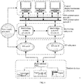
- the computer-based interlocking structure further includes an IO subsystem, a control display and maintenance subsystem, wherein the interlocking subsystem receives operation information at a human-machine dialog layer from the control display and maintenance subsystem and device status information collected by the IO subsystem, to perform a safety logic operation and perform through the IO subsystem actual control on outdoor devices.
- the IO subsystem includes an IO system I and an IO system II that are the same, and the IO system I and the IO system II are respectively connected to the interlocking system I and the interlocking system II; and each of the IO system I and the IO system II includes two CPUs having the same hardware, the two CPUs respectively run two sets of different software.
- the IO subsystem includes an IO system I and an IO system II that are the same, and the IO system I and the IO system II are respectively connected to the interlocking system I and the interlocking system II; and each of the IO system I and the IO system II includes two CPUs having heterogeneous hardware, the two CPUs respectively run two sets of different software.
- each of the IO system I and the IO system II includes an input collection unit, the input collection unit collects a static DC voltage through dynamic code sending where two independent CPU units within an input collection cage separately perform collection, and then collection results are sent to the interlocking subsystem and are compared by the interlocking subsystem; if the results are consistent through comparison, collected data are considered to be valid, otherwise, the collected data are invalid and this constitutes double 2-vote-2 fault-safety collection.
- each of the IO system I and the IO system II further includes an output unit which adopts double-break control manner, wherein two drivers comprising a dynamic driver and a static driver output in series, wherein the static output and the dynamic output are respectively controlled by two independent CPU units in an output cage, and when either of two outputs is invalid, a total output is invalid and a 2-vote-2 fault-safety output with different hardware is constituted.
- the IO subsystem adopts inherent fault-safety devices such as a transformer and a relay, and both driving circuits and collection circuits are designed as safety circuits to ensure reliability and safety of driving and collection.
- a function execution unit of the IO subsystem takes a station mechanical indoor gravity relay as a directly controlled device, and then indirectly controls outdoor signal devices through a combination of different relay circuits.
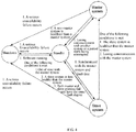
- the present disclosure further provides a redundancy switching method based on the computer-based interlocking structure, including a first system and a second system for performing master-slave redundancy switching, wherein the method includes the following steps:
- the master system or the slave system loses communication with the other system or a period starts being interrupted after entering the standby state, switching it to the master system; and if the system has a serious unavailability failure, shutting down the system.
- the computer-based interlocking system provided by the present disclosure is a signal system for realizing station interlocking by using a computer as a main technical means.
- the computer-based interlocking system constitutes an interlocking connection of both mutual relation and mutual restriction for all relatively independent signal devices in stations and sections, such as a signal machine, a track circuit, a turnout, and the like that are included in interlocking and performs centralized control, and the computer-based interlocking system is a control system that for ensuring driving safety.
- the computer-based interlocking system includes a power supply subsystem, an interlocking subsystem, IO subsystem (input and output subsystem), and a control display and maintenance subsystem.
- the power supply subsystem provides required power supply for devices of all subsystems, so that the whole interlocking system can work safely and reliably.
- the interlocking subsystem consists of an interlocking logic part, which is the core of the interlocking system.
- the interlocking subsystem receives operation information from a human-machine dialog layer of the control display and maintenance subsystem and device state information of signals, turnouts, tracks, and the like of the IO subsystem and performs safety logic operation according to the above information and generates corresponding control input, and actual control is performed by the IO subsystem on signal devices.
- the IO subsystem is composed of collection drive devices of field signal devices, and the IO subsystem transforms in a safe manner a result derived from an interlocking operation into a voltage (or a current) that may enable the field signal devices to operate directly or through interface circuits of relays of the field signal devices.
- the computer-based interlocking system provided by the present disclosure adopts a double 2-vote-2 structure designed based on a fault-safety technology.
- a 2-vote-2 comparison structure is widely used in design, and heterogeneous software/hardware is adopted in 2-vote-2 combination fault-safety design, and program running starting times with a fixed difference are adopted to reduce the probability of occurrence of common-mode failures, and thus system security is improved.
- the interlocking subsystem in the computer-based interlocking system provided by the disclosure adopts 2-vote-2 combination fault-safety design.
- Hardware of master-slave dual systems (interlocking system I and interlocking system II in the figure) are consistent, but programs run by dual CPUs of each system are respectively generated by different compilers.
- system management software of the interlocking subsystem logic part and interlocking application software are developed in C language, and different compilers are used for dual CPUs in each system.
- a CPU 1 adopts Visual C++ compiler (that is, VC compiler)
- a CPU 2 adopts Watcom C compiler (that is, WC compiler).
- the dual CPUs adopt different compilers to separately compile and link the same code, and finally generate different executable files.
- WC and VC as the most important C/C++ development tools in the 1990s, have achieved great success and widespread use on the market, and are the most mature C/C++ compilers that conform to an ANSI_C standard.
- These 2 compilers are developed by 2 different companies, and executable files generated by 2 compilers are different in both allocation of data and code memory and code execution efficiency. After the same software is compiled using WC and VC, it is found through analyzing compiled files that difference in address allocation of a code segment and a data segment of the compiled files is obvious, which can prevent common-mode failures caused by memory.
- the same source code has running starting times with a fixed difference when run on the same hardware, and thus the development difficulty is lowered, the production efficiency is improved, and requirements for debugging and maintenance are lowered while reducing common-mode failures.
- an interlocking subsystem in a computer-based interlocking system always keeps synchronized during system operation;
- Two CPUs (CPU 1 and CPU 2) in interlocking system I (or interlocking system II) respectively perform independent operations, synchronize data using Communication Between Sets Interface Board and exchange the data, and generate valid external drive commands when voting results are consistent.
- the IO subsystem in the computer-based interlocking system provided by the disclosure also adopts 2-vote-2 combination fault-safety design and realizes hardware/software heterogeneity on the IO subsystem.
- the IO subsystem directly connected to field devices is designed to have an IO system I and an IO system II that are the same and that are respectively connected to the interlocking system I and the interlocking system II, and the IO system I and the IO system II are designed to be heterogeneous in software/hardware, which ensures safety of a driving and collection result, while the upper-layer interlocking subsystem will focus more on the work of safe logic operation and safe communication, and allocation of system safety implementation is more reasonably, which ensures reasonable and efficient utilization of system resources.
- an input collection unit adopts a dynamic collection manner to collect a static DC voltage through dynamic code sending, wherein two independent CPU units within an input collection cage separately perform collection, and then collection results are compared by the interlocking subsystem; if the results are consistent through comparison, collected data are considered to be valid, otherwise, the collected data are invalid and constitutes double 2-vote-2 fault-safety collection;
- an output unit adopts double-break control manner , wherein two drivers comprising a dynamic driver and a static driver output in series, wherein the static output and the dynamic output are respectively controlled by two independent CPU units in an output cage, and when either of two-way outputs is invalid, a total output is invalid and thereby a 2-vote-2 fault-safety output with different hardware is constituted.
- a function execution unit for the single channel adopts an inherent fault-safety device, where a fast error detection mechanism is designed to take measures to trigger a safety response when a fault is detected, thereby realizing a fault-safety system with a 2-vote-2 structure in the whole process from input to output.
- the inherent fault-safety device is a special component, such as a transformer and a relay, and will not lead to subsequent error output of a circuit after the component fails, thus guiding system to safe side.
- the function execution unit of the computer-based interlocking system directly controls a device of a station mechanical indoor gravity relay, and then indirectly controls outdoor signal devices through a combination of different relay circuits.
- Both the interlocking subsystem and the IO subsystem in the computer-based interlocking system provided by the present disclosure perform corresponding fault processing according to an error level, no matter which subsystem detects an error. If the interlocking subsystem detects its own fault, the interlocking subsystem carries out processing such as getting down or downgrading as standby according to the error level. If the IO subsystem detects an error, the IO subsystem first uploads fault information to the interlocking subsystem, and then performs processing such as downtime according to the fault level. After acquiring the fault information from the IO subsystem, the interlocking subsystem identifies and processes the fault and guides it to the safe side.
- Subsystems in the computer-based interlocking system provided by the present disclosure are independent of each other, and safety-related subsystems - the interlocking subsystem and the IO subsystem both adopt fault-safety design, so that fault-safety functions can be realized independently, and high safety and high availability of the system are ensured.
- both the interlocking subsystem and the IO subsystem can work independently to ensure high availability of the system.
- the present disclosure further provides a redundancy switching method based on the foregoing computer-based interlocking system.
- the present embodiments are described by using the interlocking subsystem as an example. A related technology can be easily extended to other interlocking structures.
- the redundancy switching method provided by the present disclosure includes the following steps:
- the master system or the slave system will enter a shutdown state in case of a serious unavailability failure. If the serious unavailability failure occurs to the master system, the slave system loses communication with the master system and is automatically switched to the master system. In addition, if the slave system is healthier than the master system and has a fault lower level than that of the master system, the slave system is switched to the master system. In this case, the original master system enters standby state, and if the original master system is synchronized with the current master system and are fault-free after entering the standby state, switch the original master system to the slave system.
- the slave system enters standby state when meeting one of the following conditions: not synchronized with the master system; the slave system is less healthy than the master system; and both the master system and the slave system fail and have the same fault degree.
- the master system or the slave system loses communication with the other system or a period starts being interrupted after entering the standby state, switch the slave system to the master system; and if a system has a serious unavailability failure, shutdown it.
- the computer-based interlocking system and the master-slave switching method provided by the present disclosure support regional centralized interlocking control.
- centralized control of a plurality of stations can be realized.
- An optical fiber transmission distance between adjacent stations (without a network relay) can reach up to 40 km.
- Connection using optical cables are adopted among internal devices, to ensure high reliability of information channels inside the system.
- Self-diagnosis function is perfect and fault alarm is accurately located; a graphic reproduction and printing function and a remote diagnosis function are provided.
- the structure is simple and reasonable, and safety and reliability meet the international standard; a common standard network interface is provided. Safe or non-safe communication with an external system, for example, safe communication with a wireless block center is implemented as required; and perfect supporting off-line data generation, system configuration software and testing tools are provided.
Landscapes
- Engineering & Computer Science (AREA)
- Theoretical Computer Science (AREA)
- Quality & Reliability (AREA)
- Physics & Mathematics (AREA)
- General Engineering & Computer Science (AREA)
- General Physics & Mathematics (AREA)
- Mechanical Engineering (AREA)
- Hardware Redundancy (AREA)
- Safety Devices In Control Systems (AREA)
- Multi Processors (AREA)
Priority Applications (2)
| Application Number | Priority Date | Filing Date | Title |
|---|---|---|---|
| HRP20230685TT HRP20230685T1 (hr) | 2017-10-24 | 2018-05-10 | Računalni signalno-sigurnosni sustav i metoda redundancije sklopa |
| RS20230552A RS64433B1 (sr) | 2017-10-24 | 2018-05-10 | Računarski signalno-sigurnosni sistem i njegov postupak za zamenu redundanse |
Applications Claiming Priority (2)
| Application Number | Priority Date | Filing Date | Title |
|---|---|---|---|
| CN201711001027.2A CN107992382B (zh) | 2017-10-24 | 2017-10-24 | 一种计算机联锁系统及其冗余切换方法 |
| PCT/CN2018/086255 WO2019080477A1 (zh) | 2017-10-24 | 2018-05-10 | 一种计算机联锁系统及其冗余切换方法 |
Publications (4)
| Publication Number | Publication Date |
|---|---|
| EP3690657A1 true EP3690657A1 (de) | 2020-08-05 |
| EP3690657A4 EP3690657A4 (de) | 2021-03-10 |
| EP3690657C0 EP3690657C0 (de) | 2023-06-21 |
| EP3690657B1 EP3690657B1 (de) | 2023-06-21 |
Family
ID=62029953
Family Applications (1)
| Application Number | Title | Priority Date | Filing Date |
|---|---|---|---|
| EP18869693.4A Active EP3690657B1 (de) | 2017-10-24 | 2018-05-10 | Computerbasiertes verriegelungssystem und redundanzschaltungsverfahren dafür |
Country Status (7)
| Country | Link |
|---|---|
| EP (1) | EP3690657B1 (de) |
| CN (1) | CN107992382B (de) |
| EA (1) | EA202091031A1 (de) |
| HR (1) | HRP20230685T1 (de) |
| HU (1) | HUE063100T2 (de) |
| RS (1) | RS64433B1 (de) |
| WO (1) | WO2019080477A1 (de) |
Cited By (5)
| Publication number | Priority date | Publication date | Assignee | Title |
|---|---|---|---|---|
| CN112564484A (zh) * | 2020-11-05 | 2021-03-26 | 北京全路通信信号研究设计院集团有限公司 | 一种基于物联网技术的高安全远程应急开关装置及数据处理方法 |
| CN112650047A (zh) * | 2020-12-04 | 2021-04-13 | 北京交大微联科技有限公司 | 继电器倒机控制电路、控制方法及计算机联锁系统 |
| FR3113747A1 (fr) * | 2020-09-02 | 2022-03-04 | Thales | Système électronique pour la mise en œuvre d’une fonction critique et procédé associé |
| CN114407971A (zh) * | 2021-12-16 | 2022-04-29 | 卡斯柯信号有限公司 | 一种基于首尾冗余的列车控制级别调整方法、设备及介质 |
| CN115140129A (zh) * | 2022-09-05 | 2022-10-04 | 卡斯柯信号(北京)有限公司 | 一种列车占用回执信息的调整方法及装置 |
Families Citing this family (43)
| Publication number | Priority date | Publication date | Assignee | Title |
|---|---|---|---|---|
| CN107992382B (zh) * | 2017-10-24 | 2020-12-29 | 北京全路通信信号研究设计院集团有限公司 | 一种计算机联锁系统及其冗余切换方法 |
| CN110936982B (zh) * | 2018-09-21 | 2023-01-06 | 比亚迪股份有限公司 | 列车全自动驾驶控制方法、装置和无人驾驶列车信号系统 |
| CN109442214B (zh) * | 2018-10-24 | 2021-04-09 | 浙江浙能天然气运行有限公司 | 一种天然气场站输气方法 |
| CN109739568B (zh) * | 2018-12-19 | 2021-12-21 | 卡斯柯信号有限公司 | 一种基于2乘2取2架构的安全平台启动方法 |
| CN109649446B (zh) * | 2018-12-21 | 2024-05-31 | 中国铁道科学研究院集团有限公司通信信号研究所 | 一种多重冗余网络化的计算机联锁人机交互系统 |
| CN109976208A (zh) * | 2018-12-28 | 2019-07-05 | 上海亨钧科技股份有限公司 | 一种联锁i/o系统及控制方法 |
| CN109849969A (zh) * | 2019-01-11 | 2019-06-07 | 宝鸡文理学院 | 一种计算机联锁系统 |
| CN110293999B (zh) * | 2019-04-30 | 2021-06-04 | 北京交大思诺科技股份有限公司 | 一种安全型lkj制动控制方式 |
| CN111007713A (zh) * | 2019-07-10 | 2020-04-14 | 沈阳中科一唯电子技术有限公司 | 一种符合功能安全的异构冗余整车控制器 |
| CN110871775B (zh) * | 2019-11-12 | 2023-06-30 | 西安航空制动科技有限公司 | 一种飞机刹车主备通道闭锁控制系统及其控制方法 |
| CN111186463A (zh) * | 2020-01-16 | 2020-05-22 | 浙江众合科技股份有限公司 | 一种板级冗余的全电子计算机联锁系统 |
| CN111400111B (zh) * | 2020-03-12 | 2024-02-27 | 北京交大思诺科技股份有限公司 | 一种具有备机失步状态的安全计算机平台 |
| CN112130448B (zh) * | 2020-09-25 | 2024-06-21 | 北京交大思诺科技股份有限公司 | 一种双机主备切换的方法 |
| CN112238947B (zh) * | 2020-10-26 | 2023-10-13 | 航宇救生装备有限公司 | 一种弹射模式切换控制的电子式指令弹射系统 |
| CN112596991B (zh) * | 2020-12-27 | 2023-09-08 | 卡斯柯信号有限公司 | 一种基于机器健康状态的热备倒切方法 |
| CN112783036B (zh) * | 2020-12-30 | 2022-05-10 | 交控科技股份有限公司 | 列车自动控制系统 |
| CN113806067B (zh) * | 2021-07-28 | 2024-03-29 | 卡斯柯信号有限公司 | 基于车车通信的安全数据校验方法、装置、设备及介质 |
| CN114237990B (zh) * | 2021-11-18 | 2024-04-26 | 通号万全信号设备有限公司 | 一种基于fpga芯片的二乘冗余切换方法及装置 |
| CN114407975B (zh) * | 2021-12-21 | 2024-04-19 | 合肥工大高科信息科技股份有限公司 | 一种全电子联锁系统执行单元的热备方法及热备联锁系统 |
| CN114280918A (zh) * | 2021-12-29 | 2022-04-05 | 交控科技股份有限公司 | 多方向联锁倒切系统和轨道控制系统 |
| CN114003429B (zh) * | 2021-12-30 | 2022-03-29 | 中国铁道科学研究院集团有限公司通信信号研究所 | 基于2oo2×2的安全苛求系统的双系状态控制方法和系统 |
| CN114553376B (zh) * | 2022-01-06 | 2024-04-30 | 北京全路通信信号研究设计院集团有限公司 | 用于计算机联锁系统的二乘二取二平台通信方法及系统 |
| CN114516355B (zh) * | 2022-02-23 | 2024-03-12 | 浙江众合科技股份有限公司 | 一种基于铁路全线车站智能管控系统 |
| CN114337944B (zh) * | 2022-03-16 | 2023-04-14 | 中国人民解放军海军工程大学 | 一种系统级主备冗余通用控制方法 |
| CN114735048B (zh) * | 2022-03-17 | 2024-06-04 | 浙江众合科技股份有限公司 | 一种基于powerlink总线架构的全电子联锁系统 |
| CN114780382A (zh) * | 2022-03-18 | 2022-07-22 | 南京南瑞继保电气有限公司 | 安全冗余编译运行方法、计算机设备及可读存储介质 |
| CN114675918A (zh) * | 2022-03-22 | 2022-06-28 | 重庆市珞宾信息技术有限公司 | 一种装维终端子系统应用运行方法 |
| CN114954576B (zh) * | 2022-05-23 | 2023-10-13 | 北京交大微联科技有限公司 | 联锁系统中与无线闭塞中心通信时通信机的实现结构 |
| CN115309607B (zh) * | 2022-08-05 | 2025-07-29 | 卡斯柯信号有限公司 | 一种计算机联锁测试方法 |
| CN115933469B (zh) * | 2022-12-02 | 2024-11-12 | 中铁工程设计咨询集团有限公司 | 一种基于工业以太网的轨道交通车载控制方法和系统 |
| CN115892147B (zh) * | 2022-12-08 | 2025-06-06 | 通号万全信号设备有限公司 | 基于联锁进路和联锁功能角度的计算机自动控制测试方法 |
| CN116302715A (zh) * | 2023-02-20 | 2023-06-23 | 北京全路通信信号研究设计院集团有限公司 | 一种计算机联锁系统及其主备系冗余切换方法 |
| CN116534083B (zh) * | 2023-06-25 | 2025-08-19 | 哈尔滨市科佳通用机电股份有限公司 | 机车信号设备双系降级切换方法 |
| CN116803819A (zh) * | 2023-06-26 | 2023-09-26 | 卡斯柯信号有限公司 | 面向通信节点的计算机联锁系统双机自动切换的方法 |
| CN116684260B (zh) * | 2023-07-31 | 2023-11-28 | 卡斯柯信号(北京)有限公司 | 一种用于全电子联锁系统的新型应急盘及其控制方法 |
| CN117130833B (zh) * | 2023-08-14 | 2025-09-02 | 南京航空航天大学 | 基于程序异构关系图的sdc错误检测方法 |
| CN116767305B (zh) * | 2023-08-21 | 2023-11-17 | 北京全路通信信号研究设计院集团有限公司 | 一种全电子编码和信号传递装置及方法 |
| CN117360582A (zh) * | 2023-11-03 | 2024-01-09 | 新誉集团有限公司 | 一种车载安全数字量输入输出装置及协同检测方法 |
| CN117985072A (zh) * | 2024-02-02 | 2024-05-07 | 通号城市轨道交通技术有限公司 | 车载列控系统、控制方法、电子设备及存储介质 |
| CN118348855A (zh) * | 2024-04-17 | 2024-07-16 | 南京南瑞继保电气有限公司 | 一种冗余i/o模块的运行方法、设备及存储介质 |
| CN118426291B (zh) * | 2024-06-28 | 2024-10-11 | 比亚迪股份有限公司 | 系统控制方法、存储介质、程序产品及电子设备 |
| CN118953466A (zh) * | 2024-10-17 | 2024-11-15 | 沈阳铁路信号有限责任公司 | 一种基于6502联锁控制台的数字化控制系统及方法 |
| CN119556551A (zh) * | 2025-01-23 | 2025-03-04 | 北京全路通信信号研究设计院集团有限公司 | 一种道岔转辙机的冗余控制实现方法、装置、设备及介质 |
Family Cites Families (11)
| Publication number | Priority date | Publication date | Assignee | Title |
|---|---|---|---|---|
| US5261092A (en) * | 1990-09-26 | 1993-11-09 | Honeywell Inc. | Synchronizing slave processors through eavesdrop by one on periodic sync-verify messages directed to another followed by comparison of individual status |
| CN101580073B (zh) * | 2008-05-12 | 2012-01-25 | 卡斯柯信号有限公司 | 计算机联锁系统码位级冗余方法 |
| CN101876928B (zh) * | 2009-11-13 | 2012-07-25 | 北京全路通信信号研究设计院有限公司 | 一种二乘二取二系统的同步方法和设备 |
| CN101833490B (zh) * | 2010-03-31 | 2012-05-30 | 卡斯柯信号有限公司 | 基于软硬件相异性的二取二安全平台的信息处理方法 |
| CN201909961U (zh) * | 2010-05-18 | 2011-07-27 | 北京捷世伟业电子科技有限公司 | 一种冗余控制系统 |
| CN102381342B (zh) * | 2011-08-31 | 2014-08-13 | 北京和利时系统工程有限公司 | 一种计算机联锁系统及其控制城市轨道交通信号的方法 |
| CN102945221A (zh) * | 2012-10-18 | 2013-02-27 | 上海亨钧科技有限公司 | 一种全电子安全计算机联锁系统 |
| CN103176870B (zh) * | 2013-03-21 | 2014-12-03 | 中国铁道科学研究院 | 一种多模式信息交互的冗余安全计算机平台 |
| CN104268037A (zh) * | 2014-09-10 | 2015-01-07 | 上海自仪泰雷兹交通自动化系统有限公司 | 热冗余联锁子系统及其主备切换方法 |
| CN106095626A (zh) * | 2016-06-21 | 2016-11-09 | 浙江众合科技股份有限公司 | 改进型二取二架构 |
| CN107992382B (zh) * | 2017-10-24 | 2020-12-29 | 北京全路通信信号研究设计院集团有限公司 | 一种计算机联锁系统及其冗余切换方法 |
-
2017
- 2017-10-24 CN CN201711001027.2A patent/CN107992382B/zh active Active
-
2018
- 2018-05-10 RS RS20230552A patent/RS64433B1/sr unknown
- 2018-05-10 EP EP18869693.4A patent/EP3690657B1/de active Active
- 2018-05-10 EA EA202091031A patent/EA202091031A1/ru unknown
- 2018-05-10 WO PCT/CN2018/086255 patent/WO2019080477A1/zh not_active Ceased
- 2018-05-10 HU HUE18869693A patent/HUE063100T2/hu unknown
- 2018-05-10 HR HRP20230685TT patent/HRP20230685T1/hr unknown
Cited By (8)
| Publication number | Priority date | Publication date | Assignee | Title |
|---|---|---|---|---|
| FR3113747A1 (fr) * | 2020-09-02 | 2022-03-04 | Thales | Système électronique pour la mise en œuvre d’une fonction critique et procédé associé |
| WO2022049135A1 (fr) * | 2020-09-02 | 2022-03-10 | Thales | Système électronique pour la mise en œuvre d'une fonction critique et procédé associé |
| CN112564484A (zh) * | 2020-11-05 | 2021-03-26 | 北京全路通信信号研究设计院集团有限公司 | 一种基于物联网技术的高安全远程应急开关装置及数据处理方法 |
| CN112564484B (zh) * | 2020-11-05 | 2022-04-12 | 北京全路通信信号研究设计院集团有限公司 | 一种基于物联网技术的高安全远程应急开关装置及数据处理方法 |
| CN112650047A (zh) * | 2020-12-04 | 2021-04-13 | 北京交大微联科技有限公司 | 继电器倒机控制电路、控制方法及计算机联锁系统 |
| CN114407971A (zh) * | 2021-12-16 | 2022-04-29 | 卡斯柯信号有限公司 | 一种基于首尾冗余的列车控制级别调整方法、设备及介质 |
| CN114407971B (zh) * | 2021-12-16 | 2023-09-08 | 卡斯柯信号有限公司 | 一种基于首尾冗余的列车控制级别调整方法、设备及介质 |
| CN115140129A (zh) * | 2022-09-05 | 2022-10-04 | 卡斯柯信号(北京)有限公司 | 一种列车占用回执信息的调整方法及装置 |
Also Published As
| Publication number | Publication date |
|---|---|
| EA202091031A1 (ru) | 2020-09-30 |
| RS64433B1 (sr) | 2023-09-29 |
| WO2019080477A1 (zh) | 2019-05-02 |
| HRP20230685T1 (hr) | 2023-11-10 |
| EP3690657C0 (de) | 2023-06-21 |
| CN107992382A (zh) | 2018-05-04 |
| EP3690657A4 (de) | 2021-03-10 |
| EP3690657B1 (de) | 2023-06-21 |
| CN107992382B (zh) | 2020-12-29 |
| HUE063100T2 (hu) | 2023-12-28 |
Similar Documents
| Publication | Publication Date | Title |
|---|---|---|
| EP3690657B1 (de) | Computerbasiertes verriegelungssystem und redundanzschaltungsverfahren dafür | |
| CN105187248B (zh) | 一种冗余切换系统 | |
| CN110361979A (zh) | 一种铁路信号领域的安全计算机平台 | |
| CN109946956A (zh) | 一种设备主备系同步和热备方法 | |
| CN102955903B (zh) | 一种轨道交通计算机控制系统安全苛求信息的处理方法 | |
| US11904918B2 (en) | Computer interlocking system and switching control method for the same, device, and storage medium | |
| WO2009137988A1 (zh) | 计算机联锁系统码位级冗余方法 | |
| CN102193543B (zh) | 基于现场总线冗余网络拓扑结构的控制系统及其切换方法 | |
| CN113157499B (zh) | 一种基于云计算的安全计算机平台 | |
| CN103645715A (zh) | 一种双机热备的列车自动驾驶系统 | |
| WO2022100232A1 (zh) | 一种分布式车载安全计算机系统 | |
| CN103057572A (zh) | 一种主备机的控制切换方法 | |
| CN112550362B (zh) | 一种列车控制器的重启方法 | |
| CN115892144B (zh) | 一种tacs系统主备定位转换方法、装置、设备及介质 | |
| CN110758489A (zh) | 一种列车自动防护系统 | |
| CN112693495A (zh) | 一种无节点分布式道岔安全驱采控制系统 | |
| RU2495778C2 (ru) | Микропроцессорная система централизации стрелок и сигналов | |
| CN115593472A (zh) | 一种列车重定位方法、装置、电子设备及介质 | |
| CN113835337B (zh) | 一种列车网络冗余控制的方法与系统 | |
| CN216411911U (zh) | 一种用于舞台机械的双冗余控制系统 | |
| CN114475697B (zh) | 一种低频发码设备及发码方法 | |
| CA3148590A1 (en) | Apparatus and method for controlling a railway system | |
| CN202142052U (zh) | 列控车载设备的安全冗余计算机系统 | |
| CN114407975B (zh) | 一种全电子联锁系统执行单元的热备方法及热备联锁系统 | |
| CN107672624B (zh) | 铁路区间光纤网络信号控制装置及系统 |
Legal Events
| Date | Code | Title | Description |
|---|---|---|---|
| STAA | Information on the status of an ep patent application or granted ep patent |
Free format text: STATUS: THE INTERNATIONAL PUBLICATION HAS BEEN MADE |
|
| PUAI | Public reference made under article 153(3) epc to a published international application that has entered the european phase |
Free format text: ORIGINAL CODE: 0009012 |
|
| STAA | Information on the status of an ep patent application or granted ep patent |
Free format text: STATUS: REQUEST FOR EXAMINATION WAS MADE |
|
| 17P | Request for examination filed |
Effective date: 20200429 |
|
| AK | Designated contracting states |
Kind code of ref document: A1 Designated state(s): AL AT BE BG CH CY CZ DE DK EE ES FI FR GB GR HR HU IE IS IT LI LT LU LV MC MK MT NL NO PL PT RO RS SE SI SK SM TR |
|
| AX | Request for extension of the european patent |
Extension state: BA ME |
|
| RIC1 | Information provided on ipc code assigned before grant |
Ipc: G06F 11/20 20060101AFI20201104BHEP Ipc: B61L 19/06 20060101ALI20201104BHEP Ipc: G06F 11/14 20060101ALI20201104BHEP Ipc: G06F 11/16 20060101ALI20201104BHEP |
|
| DAV | Request for validation of the european patent (deleted) | ||
| DAX | Request for extension of the european patent (deleted) | ||
| A4 | Supplementary search report drawn up and despatched |
Effective date: 20210210 |
|
| RIC1 | Information provided on ipc code assigned before grant |
Ipc: G06F 11/16 20060101ALI20210204BHEP Ipc: B61L 19/06 20060101ALI20210204BHEP Ipc: G06F 11/20 20060101AFI20210204BHEP Ipc: G06F 11/14 20060101ALI20210204BHEP |
|
| STAA | Information on the status of an ep patent application or granted ep patent |
Free format text: STATUS: EXAMINATION IS IN PROGRESS |
|
| 17Q | First examination report despatched |
Effective date: 20221108 |
|
| RIC1 | Information provided on ipc code assigned before grant |
Ipc: B61L 27/30 20220101ALI20221202BHEP Ipc: B61L 19/06 20060101ALI20221202BHEP Ipc: G06F 11/16 20060101ALI20221202BHEP Ipc: G06F 11/14 20060101ALI20221202BHEP Ipc: G06F 11/20 20060101AFI20221202BHEP |
|
| GRAP | Despatch of communication of intention to grant a patent |
Free format text: ORIGINAL CODE: EPIDOSNIGR1 |
|
| STAA | Information on the status of an ep patent application or granted ep patent |
Free format text: STATUS: GRANT OF PATENT IS INTENDED |
|
| INTG | Intention to grant announced |
Effective date: 20230120 |
|
| GRAS | Grant fee paid |
Free format text: ORIGINAL CODE: EPIDOSNIGR3 |
|
| GRAA | (expected) grant |
Free format text: ORIGINAL CODE: 0009210 |
|
| STAA | Information on the status of an ep patent application or granted ep patent |
Free format text: STATUS: THE PATENT HAS BEEN GRANTED |
|
| AK | Designated contracting states |
Kind code of ref document: B1 Designated state(s): AL AT BE BG CH CY CZ DE DK EE ES FI FR GB GR HR HU IE IS IT LI LT LU LV MC MK MT NL NO PL PT RO RS SE SI SK SM TR |
|
| REG | Reference to a national code |
Ref country code: CH Ref legal event code: EP |
|
| REG | Reference to a national code |
Ref country code: DE Ref legal event code: R096 Ref document number: 602018052235 Country of ref document: DE |
|
| REG | Reference to a national code |
Ref country code: AT Ref legal event code: REF Ref document number: 1581389 Country of ref document: AT Kind code of ref document: T Effective date: 20230715 |
|
| REG | Reference to a national code |
Ref country code: IE Ref legal event code: FG4D |
|
| U01 | Request for unitary effect filed |
Effective date: 20230720 |
|
| U07 | Unitary effect registered |
Designated state(s): AT BE BG DE DK EE FI FR IT LT LU LV MT NL PT SE SI Effective date: 20230725 |
|
| REG | Reference to a national code |
Ref country code: RO Ref legal event code: EPE |
|
| REG | Reference to a national code |
Ref country code: LT Ref legal event code: MG9D |
|
| PG25 | Lapsed in a contracting state [announced via postgrant information from national office to epo] |
Ref country code: NO Free format text: LAPSE BECAUSE OF FAILURE TO SUBMIT A TRANSLATION OF THE DESCRIPTION OR TO PAY THE FEE WITHIN THE PRESCRIBED TIME-LIMIT Effective date: 20230921 |
|
| REG | Reference to a national code |
Ref country code: HR Ref legal event code: T1PR Ref document number: P20230685 Country of ref document: HR |
|
| PG25 | Lapsed in a contracting state [announced via postgrant information from national office to epo] |
Ref country code: GR Free format text: LAPSE BECAUSE OF FAILURE TO SUBMIT A TRANSLATION OF THE DESCRIPTION OR TO PAY THE FEE WITHIN THE PRESCRIBED TIME-LIMIT Effective date: 20230922 |
|
| REG | Reference to a national code |
Ref country code: HU Ref legal event code: AG4A Ref document number: E063100 Country of ref document: HU |
|
| PG25 | Lapsed in a contracting state [announced via postgrant information from national office to epo] |
Ref country code: SK Free format text: LAPSE BECAUSE OF FAILURE TO SUBMIT A TRANSLATION OF THE DESCRIPTION OR TO PAY THE FEE WITHIN THE PRESCRIBED TIME-LIMIT Effective date: 20230621 |
|
| PG25 | Lapsed in a contracting state [announced via postgrant information from national office to epo] |
Ref country code: ES Free format text: LAPSE BECAUSE OF FAILURE TO SUBMIT A TRANSLATION OF THE DESCRIPTION OR TO PAY THE FEE WITHIN THE PRESCRIBED TIME-LIMIT Effective date: 20230621 |
|
| PG25 | Lapsed in a contracting state [announced via postgrant information from national office to epo] |
Ref country code: IS Free format text: LAPSE BECAUSE OF FAILURE TO SUBMIT A TRANSLATION OF THE DESCRIPTION OR TO PAY THE FEE WITHIN THE PRESCRIBED TIME-LIMIT Effective date: 20231021 |
|
| PG25 | Lapsed in a contracting state [announced via postgrant information from national office to epo] |
Ref country code: SM Free format text: LAPSE BECAUSE OF FAILURE TO SUBMIT A TRANSLATION OF THE DESCRIPTION OR TO PAY THE FEE WITHIN THE PRESCRIBED TIME-LIMIT Effective date: 20230621 Ref country code: SK Free format text: LAPSE BECAUSE OF FAILURE TO SUBMIT A TRANSLATION OF THE DESCRIPTION OR TO PAY THE FEE WITHIN THE PRESCRIBED TIME-LIMIT Effective date: 20230621 Ref country code: IS Free format text: LAPSE BECAUSE OF FAILURE TO SUBMIT A TRANSLATION OF THE DESCRIPTION OR TO PAY THE FEE WITHIN THE PRESCRIBED TIME-LIMIT Effective date: 20231021 Ref country code: ES Free format text: LAPSE BECAUSE OF FAILURE TO SUBMIT A TRANSLATION OF THE DESCRIPTION OR TO PAY THE FEE WITHIN THE PRESCRIBED TIME-LIMIT Effective date: 20230621 Ref country code: CZ Free format text: LAPSE BECAUSE OF FAILURE TO SUBMIT A TRANSLATION OF THE DESCRIPTION OR TO PAY THE FEE WITHIN THE PRESCRIBED TIME-LIMIT Effective date: 20230621 |
|
| PG25 | Lapsed in a contracting state [announced via postgrant information from national office to epo] |
Ref country code: PL Free format text: LAPSE BECAUSE OF FAILURE TO SUBMIT A TRANSLATION OF THE DESCRIPTION OR TO PAY THE FEE WITHIN THE PRESCRIBED TIME-LIMIT Effective date: 20230621 |
|
| REG | Reference to a national code |
Ref country code: DE Ref legal event code: R026 Ref document number: 602018052235 Country of ref document: DE |
|
| PLBI | Opposition filed |
Free format text: ORIGINAL CODE: 0009260 |
|
| PLAX | Notice of opposition and request to file observation + time limit sent |
Free format text: ORIGINAL CODE: EPIDOSNOBS2 |
|
| 26 | Opposition filed |
Opponent name: AZD PRAHA S.R.O. Effective date: 20240321 |
|
| PLBB | Reply of patent proprietor to notice(s) of opposition received |
Free format text: ORIGINAL CODE: EPIDOSNOBS3 |
|
| REG | Reference to a national code |
Ref country code: HR Ref legal event code: ODRP Ref document number: P20230685 Country of ref document: HR Payment date: 20240503 Year of fee payment: 7 |
|
| U20 | Renewal fee for the european patent with unitary effect paid |
Year of fee payment: 7 Effective date: 20240506 |
|
| REG | Reference to a national code |
Ref country code: CH Ref legal event code: PL |
|
| PG25 | Lapsed in a contracting state [announced via postgrant information from national office to epo] |
Ref country code: MC Free format text: LAPSE BECAUSE OF FAILURE TO SUBMIT A TRANSLATION OF THE DESCRIPTION OR TO PAY THE FEE WITHIN THE PRESCRIBED TIME-LIMIT Effective date: 20230621 |
|
| GBPC | Gb: european patent ceased through non-payment of renewal fee |
Effective date: 20240510 |
|
| PG25 | Lapsed in a contracting state [announced via postgrant information from national office to epo] |
Ref country code: MC Free format text: LAPSE BECAUSE OF FAILURE TO SUBMIT A TRANSLATION OF THE DESCRIPTION OR TO PAY THE FEE WITHIN THE PRESCRIBED TIME-LIMIT Effective date: 20230621 Ref country code: CH Free format text: LAPSE BECAUSE OF NON-PAYMENT OF DUE FEES Effective date: 20240531 |
|
| PG25 | Lapsed in a contracting state [announced via postgrant information from national office to epo] |
Ref country code: IE Free format text: LAPSE BECAUSE OF NON-PAYMENT OF DUE FEES Effective date: 20240510 |
|
| PG25 | Lapsed in a contracting state [announced via postgrant information from national office to epo] |
Ref country code: GB Free format text: LAPSE BECAUSE OF NON-PAYMENT OF DUE FEES Effective date: 20240510 |
|
| U20 | Renewal fee for the european patent with unitary effect paid |
Year of fee payment: 8 Effective date: 20250403 |
|
| PLBP | Opposition withdrawn |
Free format text: ORIGINAL CODE: 0009264 |
|
| PLBD | Termination of opposition procedure: decision despatched |
Free format text: ORIGINAL CODE: EPIDOSNOPC1 |
|
| REG | Reference to a national code |
Ref country code: HR Ref legal event code: ODRP Ref document number: P20230685 Country of ref document: HR Payment date: 20250415 Year of fee payment: 8 |
|
| PGFP | Annual fee paid to national office [announced via postgrant information from national office to epo] |
Ref country code: RS Payment date: 20250408 Year of fee payment: 8 Ref country code: HU Payment date: 20250526 Year of fee payment: 8 |
|
| PGFP | Annual fee paid to national office [announced via postgrant information from national office to epo] |
Ref country code: HR Payment date: 20250415 Year of fee payment: 8 |
|
| PGFP | Annual fee paid to national office [announced via postgrant information from national office to epo] |
Ref country code: RO Payment date: 20250422 Year of fee payment: 8 |
|
| PGFP | Annual fee paid to national office [announced via postgrant information from national office to epo] |
Ref country code: TR Payment date: 20250403 Year of fee payment: 8 |
|
| PLBM | Termination of opposition procedure: date of legal effect published |
Free format text: ORIGINAL CODE: 0009276 |
|
| PG25 | Lapsed in a contracting state [announced via postgrant information from national office to epo] |
Ref country code: CY Free format text: LAPSE BECAUSE OF FAILURE TO SUBMIT A TRANSLATION OF THE DESCRIPTION OR TO PAY THE FEE WITHIN THE PRESCRIBED TIME-LIMIT; INVALID AB INITIO Effective date: 20180510 |
|
| 27C | Opposition proceedings terminated |
Effective date: 20250516 |