EP3690609A1 - Procédé et système de commande de machines dentaires - Google Patents
Procédé et système de commande de machines dentaires Download PDFInfo
- Publication number
- EP3690609A1 EP3690609A1 EP19000055.4A EP19000055A EP3690609A1 EP 3690609 A1 EP3690609 A1 EP 3690609A1 EP 19000055 A EP19000055 A EP 19000055A EP 3690609 A1 EP3690609 A1 EP 3690609A1
- Authority
- EP
- European Patent Office
- Prior art keywords
- user interface
- augmented reality
- interface
- control
- control elements
- Prior art date
- Legal status (The legal status is an assumption and is not a legal conclusion. Google has not performed a legal analysis and makes no representation as to the accuracy of the status listed.)
- Granted
Links
- 238000000034 method Methods 0.000 title claims abstract description 40
- 230000003190 augmentative effect Effects 0.000 claims abstract description 99
- 238000012800 visualization Methods 0.000 claims description 15
- 230000009471 action Effects 0.000 claims description 4
- 241000237519 Bivalvia Species 0.000 claims 1
- 235000020639 clam Nutrition 0.000 claims 1
- 210000001364 upper extremity Anatomy 0.000 abstract description 9
- 210000003141 lower extremity Anatomy 0.000 abstract description 3
- 238000004891 communication Methods 0.000 description 12
- 239000011521 glass Substances 0.000 description 11
- 230000006870 function Effects 0.000 description 4
- 230000003287 optical effect Effects 0.000 description 4
- 238000004590 computer program Methods 0.000 description 3
- 238000010586 diagram Methods 0.000 description 3
- 230000003993 interaction Effects 0.000 description 3
- 230000008569 process Effects 0.000 description 3
- 238000012545 processing Methods 0.000 description 3
- 239000000523 sample Substances 0.000 description 3
- 230000003416 augmentation Effects 0.000 description 2
- 230000008859 change Effects 0.000 description 2
- 239000002131 composite material Substances 0.000 description 2
- 238000001727 in vivo Methods 0.000 description 2
- 239000000463 material Substances 0.000 description 2
- 230000000007 visual effect Effects 0.000 description 2
- 230000008901 benefit Effects 0.000 description 1
- 239000008280 blood Substances 0.000 description 1
- 210000004369 blood Anatomy 0.000 description 1
- 230000001413 cellular effect Effects 0.000 description 1
- 238000007408 cone-beam computed tomography Methods 0.000 description 1
- 238000013461 design Methods 0.000 description 1
- 238000005516 engineering process Methods 0.000 description 1
- 239000000835 fiber Substances 0.000 description 1
- 230000004927 fusion Effects 0.000 description 1
- 238000002675 image-guided surgery Methods 0.000 description 1
- 238000003384 imaging method Methods 0.000 description 1
- 238000011503 in vivo imaging Methods 0.000 description 1
- 230000000670 limiting effect Effects 0.000 description 1
- 238000001000 micrograph Methods 0.000 description 1
- 238000000386 microscopy Methods 0.000 description 1
- 238000003909 pattern recognition Methods 0.000 description 1
- 238000009877 rendering Methods 0.000 description 1
- 230000004044 response Effects 0.000 description 1
- 210000003296 saliva Anatomy 0.000 description 1
- 239000004984 smart glass Substances 0.000 description 1
- 230000003068 static effect Effects 0.000 description 1
- 238000001356 surgical procedure Methods 0.000 description 1
- 238000012360 testing method Methods 0.000 description 1
Images


Classifications
-
- A—HUMAN NECESSITIES
- A61—MEDICAL OR VETERINARY SCIENCE; HYGIENE
- A61B—DIAGNOSIS; SURGERY; IDENTIFICATION
- A61B34/00—Computer-aided surgery; Manipulators or robots specially adapted for use in surgery
- A61B34/25—User interfaces for surgical systems
-
- A—HUMAN NECESSITIES
- A61—MEDICAL OR VETERINARY SCIENCE; HYGIENE
- A61B—DIAGNOSIS; SURGERY; IDENTIFICATION
- A61B17/00—Surgical instruments, devices or methods, e.g. tourniquets
- A61B17/24—Surgical instruments, devices or methods, e.g. tourniquets for use in the oral cavity, larynx, bronchial passages or nose; Tongue scrapers
-
- A—HUMAN NECESSITIES
- A61—MEDICAL OR VETERINARY SCIENCE; HYGIENE
- A61B—DIAGNOSIS; SURGERY; IDENTIFICATION
- A61B34/00—Computer-aided surgery; Manipulators or robots specially adapted for use in surgery
- A61B34/10—Computer-aided planning, simulation or modelling of surgical operations
-
- A—HUMAN NECESSITIES
- A61—MEDICAL OR VETERINARY SCIENCE; HYGIENE
- A61B—DIAGNOSIS; SURGERY; IDENTIFICATION
- A61B90/00—Instruments, implements or accessories specially adapted for surgery or diagnosis and not covered by any of the groups A61B1/00 - A61B50/00, e.g. for luxation treatment or for protecting wound edges
- A61B90/36—Image-producing devices or illumination devices not otherwise provided for
- A61B90/37—Surgical systems with images on a monitor during operation
-
- A—HUMAN NECESSITIES
- A61—MEDICAL OR VETERINARY SCIENCE; HYGIENE
- A61C—DENTISTRY; APPARATUS OR METHODS FOR ORAL OR DENTAL HYGIENE
- A61C1/00—Dental machines for boring or cutting ; General features of dental machines or apparatus, e.g. hand-piece design
- A61C1/0007—Control devices or systems
-
- A—HUMAN NECESSITIES
- A61—MEDICAL OR VETERINARY SCIENCE; HYGIENE
- A61C—DENTISTRY; APPARATUS OR METHODS FOR ORAL OR DENTAL HYGIENE
- A61C1/00—Dental machines for boring or cutting ; General features of dental machines or apparatus, e.g. hand-piece design
- A61C1/0007—Control devices or systems
- A61C1/0015—Electrical systems
- A61C1/0023—Foot control
-
- G—PHYSICS
- G06—COMPUTING; CALCULATING OR COUNTING
- G06F—ELECTRIC DIGITAL DATA PROCESSING
- G06F3/00—Input arrangements for transferring data to be processed into a form capable of being handled by the computer; Output arrangements for transferring data from processing unit to output unit, e.g. interface arrangements
- G06F3/01—Input arrangements or combined input and output arrangements for interaction between user and computer
- G06F3/011—Arrangements for interaction with the human body, e.g. for user immersion in virtual reality
-
- G—PHYSICS
- G06—COMPUTING; CALCULATING OR COUNTING
- G06F—ELECTRIC DIGITAL DATA PROCESSING
- G06F3/00—Input arrangements for transferring data to be processed into a form capable of being handled by the computer; Output arrangements for transferring data from processing unit to output unit, e.g. interface arrangements
- G06F3/01—Input arrangements or combined input and output arrangements for interaction between user and computer
- G06F3/03—Arrangements for converting the position or the displacement of a member into a coded form
- G06F3/033—Pointing devices displaced or positioned by the user, e.g. mice, trackballs, pens or joysticks; Accessories therefor
- G06F3/0334—Foot operated pointing devices
-
- G—PHYSICS
- G06—COMPUTING; CALCULATING OR COUNTING
- G06F—ELECTRIC DIGITAL DATA PROCESSING
- G06F3/00—Input arrangements for transferring data to be processed into a form capable of being handled by the computer; Output arrangements for transferring data from processing unit to output unit, e.g. interface arrangements
- G06F3/01—Input arrangements or combined input and output arrangements for interaction between user and computer
- G06F3/048—Interaction techniques based on graphical user interfaces [GUI]
- G06F3/0481—Interaction techniques based on graphical user interfaces [GUI] based on specific properties of the displayed interaction object or a metaphor-based environment, e.g. interaction with desktop elements like windows or icons, or assisted by a cursor's changing behaviour or appearance
- G06F3/04815—Interaction with a metaphor-based environment or interaction object displayed as three-dimensional, e.g. changing the user viewpoint with respect to the environment or object
-
- G—PHYSICS
- G06—COMPUTING; CALCULATING OR COUNTING
- G06T—IMAGE DATA PROCESSING OR GENERATION, IN GENERAL
- G06T19/00—Manipulating 3D models or images for computer graphics
- G06T19/006—Mixed reality
-
- A—HUMAN NECESSITIES
- A61—MEDICAL OR VETERINARY SCIENCE; HYGIENE
- A61B—DIAGNOSIS; SURGERY; IDENTIFICATION
- A61B17/00—Surgical instruments, devices or methods, e.g. tourniquets
- A61B2017/00973—Surgical instruments, devices or methods, e.g. tourniquets pedal-operated
-
- A—HUMAN NECESSITIES
- A61—MEDICAL OR VETERINARY SCIENCE; HYGIENE
- A61B—DIAGNOSIS; SURGERY; IDENTIFICATION
- A61B34/00—Computer-aided surgery; Manipulators or robots specially adapted for use in surgery
- A61B34/10—Computer-aided planning, simulation or modelling of surgical operations
- A61B2034/101—Computer-aided simulation of surgical operations
- A61B2034/105—Modelling of the patient, e.g. for ligaments or bones
-
- A—HUMAN NECESSITIES
- A61—MEDICAL OR VETERINARY SCIENCE; HYGIENE
- A61B—DIAGNOSIS; SURGERY; IDENTIFICATION
- A61B34/00—Computer-aided surgery; Manipulators or robots specially adapted for use in surgery
- A61B34/10—Computer-aided planning, simulation or modelling of surgical operations
- A61B2034/107—Visualisation of planned trajectories or target regions
-
- A—HUMAN NECESSITIES
- A61—MEDICAL OR VETERINARY SCIENCE; HYGIENE
- A61B—DIAGNOSIS; SURGERY; IDENTIFICATION
- A61B34/00—Computer-aided surgery; Manipulators or robots specially adapted for use in surgery
- A61B34/20—Surgical navigation systems; Devices for tracking or guiding surgical instruments, e.g. for frameless stereotaxis
- A61B2034/2046—Tracking techniques
- A61B2034/2048—Tracking techniques using an accelerometer or inertia sensor
-
- A—HUMAN NECESSITIES
- A61—MEDICAL OR VETERINARY SCIENCE; HYGIENE
- A61B—DIAGNOSIS; SURGERY; IDENTIFICATION
- A61B34/00—Computer-aided surgery; Manipulators or robots specially adapted for use in surgery
- A61B34/20—Surgical navigation systems; Devices for tracking or guiding surgical instruments, e.g. for frameless stereotaxis
- A61B2034/2046—Tracking techniques
- A61B2034/2055—Optical tracking systems
- A61B2034/2057—Details of tracking cameras
-
- A—HUMAN NECESSITIES
- A61—MEDICAL OR VETERINARY SCIENCE; HYGIENE
- A61B—DIAGNOSIS; SURGERY; IDENTIFICATION
- A61B34/00—Computer-aided surgery; Manipulators or robots specially adapted for use in surgery
- A61B34/20—Surgical navigation systems; Devices for tracking or guiding surgical instruments, e.g. for frameless stereotaxis
- A61B2034/2046—Tracking techniques
- A61B2034/2065—Tracking using image or pattern recognition
-
- A—HUMAN NECESSITIES
- A61—MEDICAL OR VETERINARY SCIENCE; HYGIENE
- A61B—DIAGNOSIS; SURGERY; IDENTIFICATION
- A61B90/00—Instruments, implements or accessories specially adapted for surgery or diagnosis and not covered by any of the groups A61B1/00 - A61B50/00, e.g. for luxation treatment or for protecting wound edges
- A61B90/36—Image-producing devices or illumination devices not otherwise provided for
- A61B2090/364—Correlation of different images or relation of image positions in respect to the body
- A61B2090/365—Correlation of different images or relation of image positions in respect to the body augmented reality, i.e. correlating a live optical image with another image
-
- A—HUMAN NECESSITIES
- A61—MEDICAL OR VETERINARY SCIENCE; HYGIENE
- A61B—DIAGNOSIS; SURGERY; IDENTIFICATION
- A61B90/00—Instruments, implements or accessories specially adapted for surgery or diagnosis and not covered by any of the groups A61B1/00 - A61B50/00, e.g. for luxation treatment or for protecting wound edges
- A61B90/36—Image-producing devices or illumination devices not otherwise provided for
- A61B90/37—Surgical systems with images on a monitor during operation
- A61B2090/372—Details of monitor hardware
-
- A—HUMAN NECESSITIES
- A61—MEDICAL OR VETERINARY SCIENCE; HYGIENE
- A61B—DIAGNOSIS; SURGERY; IDENTIFICATION
- A61B90/00—Instruments, implements or accessories specially adapted for surgery or diagnosis and not covered by any of the groups A61B1/00 - A61B50/00, e.g. for luxation treatment or for protecting wound edges
- A61B90/50—Supports for surgical instruments, e.g. articulated arms
- A61B2090/502—Headgear, e.g. helmet, spectacles
-
- A—HUMAN NECESSITIES
- A61—MEDICAL OR VETERINARY SCIENCE; HYGIENE
- A61C—DENTISTRY; APPARATUS OR METHODS FOR ORAL OR DENTAL HYGIENE
- A61C1/00—Dental machines for boring or cutting ; General features of dental machines or apparatus, e.g. hand-piece design
- A61C1/0007—Control devices or systems
- A61C1/0015—Electrical systems
-
- G—PHYSICS
- G06—COMPUTING; CALCULATING OR COUNTING
- G06T—IMAGE DATA PROCESSING OR GENERATION, IN GENERAL
- G06T2200/00—Indexing scheme for image data processing or generation, in general
- G06T2200/24—Indexing scheme for image data processing or generation, in general involving graphical user interfaces [GUIs]
-
- G—PHYSICS
- G06—COMPUTING; CALCULATING OR COUNTING
- G06T—IMAGE DATA PROCESSING OR GENERATION, IN GENERAL
- G06T2210/00—Indexing scheme for image generation or computer graphics
- G06T2210/41—Medical
Definitions
- the present application generally relates to a method, a system and a computer readable storage media for controlling machines and, more particularly, to a method, system and a computer readable storage media for utilizing an augmented reality control/user interface to operate dental machines such as a treatment unit.
- a user or control interface may be defined as the space where interactions between humans and machines occur. This may allow the control of the machine from a human end.
- the purpose of a user interface design may be to make it easy, efficient, and user-friendly to operate a machine in a way which produces a desired result.
- Common user interfaces include graphical user interfaces, gesture interfaces, hardware interfaces, tangible user interfaces, text-based user interfaces, voice-controlled user interfaces.
- a clinician may use a user/control interface of a computer, for example, to create a treatment plan, view patient radiographs, facilitate a scanning procedure etc.
- the clinician may need the use of his/her hands for conducting treatment procedures on a patient.
- a clinician wearing gloves and treating a patient may have his/her gloves come into contact with the saliva/blood of a patient and may not want to contaminate a computer mouse in order to navigate programs on a computer screen.
- Augmented Reality (AR) glasses may be used to solve this problem.
- current AR glasses may work via a touch interaction, for example, through a touch pad on a side of the AR glasses, a voice command or a gesture using the hands.
- the clinician may need his hands to conduct treatment procedures and as such controlling the AR glasses via hand gestures may hinder the treatment process.
- a touch interaction on a side of the pair AR glasses may also not be ideal as the AR glasses may subsequently need to be disinfected.
- Even further dental offices may often be loud due to, for example, treatment noise from dental machines, thereby reducing the effectiveness of voice commands for AR glasses. Therefore, there is a need for a way to control a first user interface normally controlled by the upper limbs/hands through a second user interface normally controlled by another dexterous part of the body other than the upper limbs.
- US Patent Application Publication No. 20160033770A1 describes a head-mounted display device that enables a user to visually recognize a virtual image and an external scene.
- US Patent Application No. 2017202633 discloses an imaging and display system for guiding medical interventions comprising a wearable display for viewing by a user wherein the display presents a composite, or combined image that includes pre-operative surgical navigation images, intraoperative images, and in-vivo microscopy images or sensing data.
- a probe such as a microscopy probe or a sensing probe, may be used to acquire in-vivo imaging/sensing data from the patient and the intraoperative and in-vivo images may be acquired using tracking and registration techniques to align them with the pre-operative image and the patient to form a composite image for display.
- US Patent Application No. 20020082498 discloses a method for image-guided surgery comprising capturing 3-dimensional (3D) volume data of a portion of a patient, processing the volume data so as to provide a graphical representation of the data, capturing a stereoscopic video view of a scene including a portion of said patient, rendering the graphical representation and the stereoscopic video view in a blended manner so as to provide a stereoscopic augmented image, and displaying said stereoscopic augmented image in a video-see-through display.
- 3-dimensional (3D) volume data of a portion of a patient processing the volume data so as to provide a graphical representation of the data
- capturing a stereoscopic video view of a scene including a portion of said patient rendering the graphical representation and the stereoscopic video view in a blended manner so as to provide a stereoscopic augmented image
- displaying said stereoscopic augmented image in a video-see-through display.
- US Patent Application Publication No. 20160191887 describes a real-time surgery navigation method and apparatus for displaying an augmented view of a patient from a static or dynamic viewpoint of a surgeon.
- a surface image, a graphical representation the internal anatomic structure of the patient processed from preoperative or intraoperative images, and a computer geometrically registering both images may be used.
- Responsive to geometrically registering the images a head mounted display may present to a surgeon an augmented view of the patient.
- the present invention provides a method utilizing augmented visualization, the method comprising: providing a first user interface; providing a second user interface different from the first user interface; providing an augmented reality user interface corresponding to the second user interface, the first user interface being adapted to transmit one or more control signals corresponding to the augmented reality user interface; and controlling the second user interface through the one or more control signals of the first user interface.
- the method further comprises one or more of the following steps: (i) further comprising overlaying the augmented reality user interface on the first user interface such that one or more augmented reality control elements of the augmented reality user interface correspond to one or more first control elements of the first user interface or to one or more positions of a first control element of the first user interface and such that the augmented reality user interface appears directly superimposed on the first user interface, (ii) wherein the one or more augmented reality control elements of the augmented reality interface also correspond to one or more second control elements of the second user interface, (iii) wherein the one or more second control elements include, action items, software applications, videos and/or, images, (iv) further comprising operating the first user interface in a hands-free manner, (v) further comprising; updating the augmented reality user interface based on data selected from the group consisting of (a) real time data tracking clinician movements (b) real time data tracking a location of the first user interface and (c) one or more control signals of the first user interface, (vi)
- a system utilizing augmented visualization comprising: a display device for augmented visualization; a first user interface; a second user interface different from the first user interface; and at least one processor configured to perform the steps of; providing an augmented reality user interface corresponding to the second user interface, the first user interface being adapted to transmit one or more control signals corresponding to the augmented reality user interface; and controlling the second user interface through the one or more control signals of the first user interface.
- system further comprise one or more of the following configuration: (i) further comprising a tracking system configured to offer real-time position data for a precise location and orientation of objects in a common coordinate system, (ii) wherein the tracking system is sensor based and/or vision based, (iii) wherein the first user interface is a footswitch or a disinfectable control panel.
- the processor is further configured to perform the step of: overlaying the augmented reality user interface on the first user interface such that one or more augmented reality control elements of the augmented reality user interface correspond to one or more first control elements of the first user interface or to one or more positions of a first control element of the first user interface and such that the augmented reality user interface appears directly superimposed on the first user interface, (v) wherein the one or more augmented reality control elements of the augmented reality interface also corresponds to the one or more second control elements of the second user interface, (vi) wherein the one or more second control elements include, action items, software applications, videos and/or, images, (vii) wherein the processor is further configured to perform the step of: operating the first interface in a hands free manner, (viii) wherein the processor is further configured to perform the step of: updating the augmented reality user interface based on data selected from the group consisting of (i) real time data tracking clinician movements (ii) real time data tracking a location of the first user interface and (iii) one or
- a non-transitory computer-readable storage medium storing a program which, when executed by a computer system, causes the computer system to perform a procedure
- the procedure comprising: providing an augmented reality user interface corresponding to a second user interface, receiving one or more control signals from a first user interface, said control signals corresponding to the augmented reality user interface; and controlling the second user interface through the one or more control signals of the first user interface.
- a method, system and computer readable storage media may be provided for operating machines such as dental machines through an augmented reality user/control interface.
- An augmented reality interface may enable the control of a dental machine (such as a treatment unit operated with a mouse) during dental treatment by using dexterous parts of the body other than the upper limbs (e.g. by using the lower limbs) on a first user/control interface (such as a footswitch) to send instructions corresponding to a second user interface (such as a graphical user interface) wherein the first user interface is different from the second user interface.
- the first user/control interface may preferably be hands-free but may also involve the use of the hands in an embodiment in which that first user/control interface is capable of being disinfected.
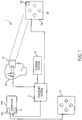
- FIG. 1 illustrates an augmented reality visualization system 1 comprising a display device 12 for augmented visualization such as (i) head mounted augmented reality glasses, (ii) an HUD display, or (iii) a stereoscopic display capable of receiving stereoscopic video images, or otherwise display device 12 that may be used for overlaying an augmented reality user interface 42 on a (i) first user interface 14 (which may preferably be a hardware user interface), or on (ii) a stereoscopic video/projection of the first interface 14 (said stereoscopic video/projection being viewed through the display device 12 ) such that the augmented reality user interface 42 appears to be directly superimposed on first user interface 14.
- a display device 12 for augmented visualization such as (i) head mounted augmented reality glasses, (ii) an HUD display, or (iii) a stereoscopic display capable of receiving stereoscopic video images, or otherwise display device 12 that may be used for overlaying an augmented reality user interface 42 on a (i) first user interface 14
- the augmented reality user interface 42 may be configured to correspond to a second user interface 15 and the second interface 15 may be controlled through the first interface 14.
- the second interface may preferably be a graphical user interface (GUI) that is normally operated with the upper limbs such as, for example, a graphical user interface of a standalone computer used by a clinician 10 for viewing X-ray images, a graphical user interface of a monitor connected to a dental treatment chair, a control panel of a dental treatment chair etc.
- GUI graphical user interface
- the second user interface 15 may be any other kind of user interface other than a GUI.
- the first user interface 14 may be a footswitch 16 or any user interface capable of being controlled by the lower limbs such that the clinician 10 may be free to use his/her upper limbs on a patient (not shown) during treatment and/or such that the clinician 10 may not infect the first user interface 15 with his/her upper limbs during treatment.
- footswitches 16 are disclosed in U.S. Patent Application Publication No. 2014/0017629A1 , entitled "Hard-Wired and Wireless System with Footswitch for Operating a Dental or Medical Treatment Apparatus", by Lint et al, and German Patent No.
- the first user interface 14 may be a disinfectable user interface such as a control panel of a dental treatment chair and may be controlled using the upper limbs.
- the clinician 10 may control functions of the second user interface 15 through the "more convenient" first user interface 14 and still be able to simultaneously use his/her upper limbs for treatment purposes. Moreover the clinician may benefit from using a technology he is familiar with (first user interface 14 ) in controlling a new application he/she may not be familiar with (second user interface 15 ).
- the display device 12 may be connected to or form part of a computer system 100.
- the computer system 100 (also shown in FIG. 3 ) may include a tracking system 2 and a processor 122.
- the tracking system 2 may alternatively be separate from the computer system and may form at least part of any of the devices, components, and/or systems discussed herein.
- the tracking system 2 may be electrically connected to a processor 122 and may offer real-time location data for a precise location and orientation of objects (such as the first user interface 14 ) and the clinician in a common coordinate system.
- the tracking system 2 may be sensor based e.g. as embedded sensors 26 or markers (not shown) in the first user interface 14 /footswitch 16 ( FIG.
- sensors such as, for example, pressure, touch, proximity, rotational, gyroscopic sensors and global positioning system (GPS), to track the position of the footswitch 16 and/or to track output/control signals of the footswitch 16, and/or as gyroscopes or accelerometers to track the movement of the clinician 14.
- GPS global positioning system
- the tracking system 2 may also be vision based, for example as cameras for visual tracking of the location of the first user interface 14 and/or predetermined markers (not shown) placed on the first user interface 14. Said visual tracking may be achieved using, for example object/pattern recognition.
- a camera system 3 such as a 3D optical tracking system and/or stereoscopic camera system may be included in the computer system and/or may form or be a part of the tracking system 2.
- the camera system 3 may also be embedded in the display device 12 of the clinician 10.
- the camera system may operate under one of several depth sensing principles in order to track a location of the first user interface 14 relative to the moving clinician 10 and vice versa in order to display the augmented reality user interface 42 on the first user interface 14 despite relative movements between the clinician 10 and the first user interface 14.
- the depth sensing principles may include, for example, (i) structural light, (ii) Time of Flight (ToF) and/or (iii) stereoscopic principles explained hereinafter.
- a light source may be used to project a known pattern onto the first user interface 14, and a receiver may detect the distortion of the reflected pattern to calculate a depth map based on geometry.
- a light source may send out a pulse toward the first user interface 14, and a sensor may detect a reflection of the pulse from the first user interface 14 in order to record it's time of flight. Knowing the time of flight and the constant speed of light, the system may calculate how far away the first user interface is.
- a modulated light source may be sent and a phase change of light reflected from the first user interface 14 may be detected.
- a modulated light source may be sent and a phase change of light reflected from the first user interface 14 may be detected.
- multiple cameras may be placed at different positions to capture multiple images of the first user interface, and a depth map may be calculated based on geometry. This depth information may be used to track the location of first user interface 14 during treatment (e.g. during dental treatment).
- the tracking system 2 may be a fusion of sensor based tracking system and a vision based tracking system.
- a wireless protocol may be used to transmit data between the computer system 100 and internal/external devices such as the first user interface.
- the processor 122 may be configured to receive real time tracking data, to analyze said data and to display the augmented reality user interface 42 to the clinician 10 in an augmented manner by (i) overlaying the augmented reality user interface 42 on the first user interface 14 or on a vicinity of the first user interface through the display device 12 or (ii) overlaying the augmented reality user interface 42 on a stereoscopic video of the first user interface 14 using e.g. a head mounted stereoscopic display capable of showing stereoscopic videos.
- the augmented reality user interface 42 may be directly projected onto the first interface 14 using projection based augmented reality systems such that the projected augmented reality user interface 42 may be viewed with the naked eye.
- the clinician 10 may control the second user interface 15 during a treatment procedure by selecting, (using the first user interface 14 ), as shown in FIG. 2 , an augmented reality control element 70 displayed in the augmented reality interface 42 corresponding to a second control element 60 displayed in the second user interface 15.
- the augmented reality control element 70 may be selected by, for example engaging a first control element 80 (e.g.
- the second control elements 60 in the second user interface may include, for example, action buttons/items (select, zoom, scroll, magnify etc.), software applications (e.g. performing a scanning procedure in multiple guided steps), video/image viewing panels (e.g. for viewing 3D images, X-ray images, scrolling through images etc.), and the like.
- the augmented reality control elements 70 may therefore be configured to correspond to the second control elements 60.
- control elements 60 a, 60 b, 60 c and 60 d in the second interface 15 correspond respectively to control elements 70 a, 70 b and 70 c, 70 d of the augmented reality user interface 42 and may be controlled by one or more first control elements 80 of the first interface or one or more positions of a first control element 80 of the first user interface 14 (e.g. a disinfectable control panel acting as a first user interface may have a plurality of first control elements 80 and a footswitch 16 may have a pedal and/or a control element capable of being engaged and placed in a plurality of positions corresponding to a plurality of output/control signals).
- a disinfectable control panel acting as a first user interface may have a plurality of first control elements 80 and a footswitch 16 may have a pedal and/or a control element capable of being engaged and placed in a plurality of positions corresponding to a plurality of output/control signals.
- the second control element 60 may be routed to the display 12 and for viewing by the clinician 10 in any position and/or may be viewed directly on the second user interface 15. In both cases the second control element 60 may be manipulated (such as edited, scrolled through, zoomed in/out of etc.) using the first control element(s) 80 of the first interface 14.
- Overlaying of the augmented reality user interface 42 on the first user interface 14 may be performed dynamically and in real time and may be achieved by the processor 122 working in tandem with the tracking system 2 wherein changes in position of (i) the clinician 10 and/or (ii) the first user interface 14, captured by the tracking system 2, may be translated into corresponding changes in positions of the overlaid augmented reality user interface 42 such that said augmented reality user interface 42 routed to a screen of the display device 12 appears directly superimposed on the first user interface 14 even as the clinician 10 moves and/or first user interface changes position.
- the processor 122 may be configured to receive one or more output/control signals from the first user interface 14 and alter second user interface 15 from a first state to a second state corresponding to the output/control signal and/or alter the augmented reality user interface 42 from another first state to another second state corresponding to said output/control signal.
- the processor 122 may display contents of A 3 on a display of the second user interface 15 for viewing.
- Contents of A 3 may be controlled (such as clicked on or zoomed in) by using the footswitch 16 to select control elements 70 b (Click) and/or control element 70 (Zoom (+)).
- the processor 122 may also change " ⁇ Next App (A3)" to " ⁇ Next App (A 4 )” and “Last App (A 1 ) ⁇ ” to "Last App (A 2 ) ⁇ ” in the augmented reality user interface 42.
- “ ⁇ Next App (A3)” to " ⁇ Next App (A 4 )”
- “Last App (A 1 ) ⁇ ” to "Last App (A 2 ) ⁇ ” in the augmented reality user interface 42.
- first user interface 14 and second user interface 15 other than those described are included in the augmented reality visualization system 1.
- the augmented reality user interface 42 may not be directly overlaid on the first user interface 14 but may be overlaid on an image (not shown) of the first user interface 14 taken by the camera system 3.
- the first user interface 14 is the footswitch/foot pedal 16
- the second interface is a control panel of a treatment center or predetermined functions of a treatment center and an augmented reality glass/smart glass may provide an the augmented reality user interface 42 wherein the footswitch/foot pedal 16, control panel of the treatment center or predetermined functions of a treatment center and augmented reality glass are paired with each other to form an augmented reality visualization system.
- FIG. 3 shows a block diagram of a computer system 100 that may be employed in accordance with at least some of the example embodiments herein.
- FIG. 3 shows a block diagram of a computer system 100 that may be employed in accordance with at least some of the example embodiments herein.
- the computer system 100 may include at least one computer processor 122 and may include a tracking system 2, user interface 126 and input unit 130.
- the first user interface 14 and second user interface 15 may be part of the computer system 100 or may be separate from the computer system.
- a display unit 128, an input unit 130, and the computer processor 122 may collectively form the user interface 126.
- the computer processor 122 may include, for example, a central processing unit, a multiple processing unit, an application-specific integrated circuit ("ASIC"), a field programmable gate array (“FPGA”), or the like.
- the processor 122 may be connected to a communication infrastructure 124 (e.g., a communications bus, or a network).
- the processor 122 may receive a request displaying an augmented reality user interface 42 and may obtain instructions concerning the request from one or more storage units of the computer system 100.
- the processor 122 may then load said instructions and execute the loaded instructions such as routing augmented reality user interface 42 to a screen of the display device 12 such that the augmented reality user interface 42 is overlaid on the first user interface 14 and such that said augmented reality user interface 42 appears directly superimposed on the first user interface 14.
- the computer system may use projection based augmented reality systems wherein, for example, a projector and depth sensors, along with the tracking system 2 and/or markers (e.g. hidden markers on the first user interface 14 ) may project the augmented reality user interface 42 directly onto the first user interface 14.
- a display 12 such as augmented reality glasses may not be needed to view the augmented reality user interface 42.
- One or more steps/procedures may be stored on a non-transitory storage device in the form of computer-readable program instructions.
- the processor 122 loads the appropriate instructions, as stored on a storage device, into memory and then executes the loaded instructions as shown in FIG. 4 which is discussed hereinafter.
- the computer system 100 may further comprise a main memory 132, which may be a random access memory ("RAM") and also may include a secondary memory 134.
- the secondary memory 134 may include, for example, a hard disk drive 136 and/or a removable-storage drive 138 (e.g., a floppy disk drive, a magnetic tape drive, an optical disk drive, a flash memory drive, and the like).
- the removable-storage drive 138 may read from and/or write to a removable storage unit 140 in a well-known manner.
- the removable storage unit 140 may be, for example, a floppy disk, a magnetic tape, an optical disk, a flash memory device, and the like, which may be written to and read from by the removable-storage drive 138.
- the removable storage unit 140 may include a non-transitory computer-readable storage medium storing computer-executable software instructions and/or data.
- the secondary memory 134 may include other computer-readable media storing computer-executable programs or other instructions to be loaded into the computer system 100.
- Such devices may include a removable storage unit 144 and an interface 142 (e.g., a program cartridge and a cartridge interface); a removable memory chip (e.g., an erasable programmable read-only memory (“EPROM”) or a programmable read-only memory (“PROM”)) and an associated memory socket; and other removable storage units 144 and interfaces 142 that allow software and data to be transferred from the removable storage unit 144 to other parts of the computer system 100.
- EPROM erasable programmable read-only memory
- PROM programmable read-only memory
- the computer system 100 also may include a communications interface 146 that enables software and data to be transferred between the computer system 100 and external devices.
- a communications interface 146 may include a modem, a network interface (e.g., an Ethernet card or a wireless interface), a communications port (e.g., a Universal Serial Bus (“USB”) port or a FireWire® port), a Personal Computer Memory Card International Association (“PCMCIA”) interface, Bluetooth®, and the like.
- Software and data transferred via the communications interface 146 may be in the form of signals, which may be electronic, electromagnetic, optical or another type of signal that may be capable of being transmitted and/or received by the communications interface 146. Signals may be provided to the communications interface 146 via a communications path 148 (e.g., a channel).
- the communications path 148 may carry signals and may be implemented using wire or cable, fiber optics, a telephone line, a cellular link, a radio-frequency ("RF") link, or the like.
- the communications interface 146 may be used to transfer software or data or other information between the computer system 100 and a remote server or cloud-based storage (not shown).
- One or more computer programs or computer control logic may be stored in the main memory 132 and/or the secondary memory 134.
- the computer programs may also be received via the communications interface 146.
- the computer programs may include computer-executable instructions which, when executed by the computer processor 122, cause the computer system 100 to perform the methods as described hereinafter.
- the software may be stored in a non-transitory computer-readable storage medium and loaded into the main memory 132 and/or the secondary memory 134 of the computer system 100 using the removable-storage drive 138, the hard disk drive 136, and/or the communications interface 146.
- Control logic when executed by the processor 122, causes the computer system 100, and more generally the augmented reality visualization system 1, to perform all or some of the some of the methods described herein.
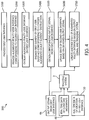
- FIG. 4 shows a flow chart of a process 200 for controlling a dental machine.
- the process may start by providing a first user interface 14 as shown in Step S 100.
- the augmented reality user interface 42 may then be provided in Step S 200 wherein said augmented reality interface 42 correspond to a second user interface 15 (or wherein augmented reality control elements 70 of the augmented reality interface 42 correspond to second control elements 60 of the second interface 15 ).
- the augmented reality user interface 42 may then be overlaid in Step S 300 on the first user interface such that augmented reality control elements 70 correspond to first control elements 80 of the first user interface 14 (or to the plurality of positions of a first control element 80 of the first user interface 14 in the case of a foot switch 16 ).
- the first control element 80 may be engaged to produce an output/control signal 46 that may correspond to an augmented reality control element 70.
- Said output/control signal 46 may be obtained in Step S 500 and the second user interface 15 may be updated in Step S 600 based on the obtained output/control signal 46. For example, an image displayed on the second user interface 15 may be zoomed into, a collection of CBCT images of a patient may be scrolled through, etc.
- Step S 700 using data from the tracking system 2 including, for example, (i) real time data tracking movements of the clinician 48 (ii) real time data tracking a location of the first user interface 14 and/or (iii) output/control signals 46 of the first user interface 14, the augmented data routed to the display device 12 may be dynamically updated in real time for overlay on the first user interface 14 such that the augmentation appears directly superimposed on said first user interface 14 and such that the augmentation is continuously updated when the first control element 80 of the first user interface 14 is engaged.
- data from the tracking system 2 including, for example, (i) real time data tracking movements of the clinician 48 (ii) real time data tracking a location of the first user interface 14 and/or (iii) output/control signals 46 of the first user interface 14, the augmented data routed to the display device 12 may be dynamically updated in real time for overlay on the first user interface 14 such that the augmentation appears directly superimposed on said first user interface 14 and such that the augmentation is continuously updated when the first control element 80 of the first user interface 14 is
- the first user interface 14 may be configured to switch between (i) a first set of operations wherein the first user interface 14 controls operations for which it was originally designed for and (ii) a second set of operations for which it was not originally designed for. It may also be configured to switch between any number of predetermined sets of operations. In yet another embodiment of the present invention, any of the sets of operations of the first user interface may be determined by the clinician 10.
- example embodiments described herein provide a method, system and computer readable storage media for controlling a machine such as a dental machine.
Landscapes
- Engineering & Computer Science (AREA)
- Health & Medical Sciences (AREA)
- Life Sciences & Earth Sciences (AREA)
- Surgery (AREA)
- Theoretical Computer Science (AREA)
- General Engineering & Computer Science (AREA)
- Human Computer Interaction (AREA)
- General Health & Medical Sciences (AREA)
- Animal Behavior & Ethology (AREA)
- Veterinary Medicine (AREA)
- Public Health (AREA)
- Nuclear Medicine, Radiotherapy & Molecular Imaging (AREA)
- General Physics & Mathematics (AREA)
- Physics & Mathematics (AREA)
- Biomedical Technology (AREA)
- Molecular Biology (AREA)
- Medical Informatics (AREA)
- Heart & Thoracic Surgery (AREA)
- Oral & Maxillofacial Surgery (AREA)
- Robotics (AREA)
- Dentistry (AREA)
- Epidemiology (AREA)
- Water Supply & Treatment (AREA)
- Software Systems (AREA)
- Computer Graphics (AREA)
- Computer Hardware Design (AREA)
- Pulmonology (AREA)
- Otolaryngology (AREA)
- Gynecology & Obstetrics (AREA)
- Radiology & Medical Imaging (AREA)
- Pathology (AREA)
- User Interface Of Digital Computer (AREA)
- Dental Tools And Instruments Or Auxiliary Dental Instruments (AREA)
- Processing Or Creating Images (AREA)
Priority Applications (9)
| Application Number | Priority Date | Filing Date | Title |
|---|---|---|---|
| EP19000055.4A EP3690609B1 (fr) | 2019-01-30 | 2019-01-30 | Procédé et système de commande de machines dentaires |
| KR1020217020781A KR20210121001A (ko) | 2019-01-30 | 2020-01-27 | 치과용 기계를 제어하기 위한 방법 및 시스템 |
| US17/427,264 US11771506B2 (en) | 2019-01-30 | 2020-01-27 | Method and system for controlling dental machines |
| BR112021007912-2A BR112021007912A2 (pt) | 2019-01-30 | 2020-01-27 | método e sistema para controlar máquinas odontológicas |
| PCT/EP2020/051872 WO2020156976A1 (fr) | 2019-01-30 | 2020-01-27 | Procédé et système de commande de machines dentaires |
| AU2020213863A AU2020213863A1 (en) | 2019-01-30 | 2020-01-27 | Method and system for controlling dental machines |
| JP2021536228A JP7524193B2 (ja) | 2019-01-30 | 2020-01-27 | 歯科機械を制御するための方法及びシステム |
| CA3117894A CA3117894A1 (fr) | 2019-01-30 | 2020-01-27 | Procede et systeme de commande de machines dentaires |
| CN202080006737.8A CN113490905B (zh) | 2019-01-30 | 2020-01-27 | 用于控制牙科机器的方法和系统 |
Applications Claiming Priority (1)
| Application Number | Priority Date | Filing Date | Title |
|---|---|---|---|
| EP19000055.4A EP3690609B1 (fr) | 2019-01-30 | 2019-01-30 | Procédé et système de commande de machines dentaires |
Publications (2)
| Publication Number | Publication Date |
|---|---|
| EP3690609A1 true EP3690609A1 (fr) | 2020-08-05 |
| EP3690609B1 EP3690609B1 (fr) | 2021-09-22 |
Family
ID=65351843
Family Applications (1)
| Application Number | Title | Priority Date | Filing Date |
|---|---|---|---|
| EP19000055.4A Active EP3690609B1 (fr) | 2019-01-30 | 2019-01-30 | Procédé et système de commande de machines dentaires |
Country Status (9)
| Country | Link |
|---|---|
| US (1) | US11771506B2 (fr) |
| EP (1) | EP3690609B1 (fr) |
| JP (1) | JP7524193B2 (fr) |
| KR (1) | KR20210121001A (fr) |
| CN (1) | CN113490905B (fr) |
| AU (1) | AU2020213863A1 (fr) |
| BR (1) | BR112021007912A2 (fr) |
| CA (1) | CA3117894A1 (fr) |
| WO (1) | WO2020156976A1 (fr) |
Citations (11)
| Publication number | Priority date | Publication date | Assignee | Title |
|---|---|---|---|---|
| US20020082498A1 (en) | 2000-10-05 | 2002-06-27 | Siemens Corporate Research, Inc. | Intra-operative image-guided neurosurgery with augmented reality visualization |
| DE102007014785A1 (de) * | 2007-03-28 | 2008-10-02 | Sirona Dental Systems Gmbh | Fußsteuereinrichtung |
| US20110016405A1 (en) * | 2009-07-17 | 2011-01-20 | Qualcomm Incorporated | Automatic interafacing between a master device and object device |
| US20140017629A1 (en) | 2006-01-17 | 2014-01-16 | Dentsply International Inc. | Hard-Wired and Wireless System with Footswitch for Operating a Dental or Medical Treatment Apparatus |
| US20160033770A1 (en) | 2013-03-26 | 2016-02-04 | Seiko Epson Corporation | Head-mounted display device, control method of head-mounted display device, and display system |
| US20160191887A1 (en) | 2014-12-30 | 2016-06-30 | Carlos Quiles Casas | Image-guided surgery with surface reconstruction and augmented reality visualization |
| US20170202633A1 (en) | 2014-02-21 | 2017-07-20 | The University Of Akron | Imaging and display system for guiding medical interventions |
| EP3223061A1 (fr) * | 2012-11-20 | 2017-09-27 | Microsoft Technology Licensing, LLC | Visiocasque et procédé de commande correspondant |
| EP3399388A1 (fr) * | 2015-12-30 | 2018-11-07 | Shenzhen Royole Technologies Co. Ltd. | Appareil d'affichage à réalité virtuelle, système d'affichage à réalité virtuelle, et procédé d'entrée |
| US10136460B2 (en) * | 2014-07-29 | 2018-11-20 | Samsung Electronics Co., Ltd | Mobile device and method of pairing the same with electronic device |
| WO2019133070A1 (fr) * | 2017-12-28 | 2019-07-04 | Ethicon Llc | Affichage de l'alignement d'une cartouche d'agrafes sur une ligne d'agrafes linéaire antérieure |
Family Cites Families (9)
| Publication number | Priority date | Publication date | Assignee | Title |
|---|---|---|---|---|
| KR100988191B1 (ko) | 2004-01-27 | 2010-10-18 | 엑스오 케어 에이/에스 | 치과 시술 조작 시스템 |
| JP5711182B2 (ja) | 2012-04-27 | 2015-04-30 | 株式会社モリタ製作所 | 医療用診療装置 |
| DE102014207127A1 (de) * | 2014-04-14 | 2015-10-15 | Siemens Aktiengesellschaft | Steuerungssystem für ein medizinisches Gerät sowie Verfahren zum Steuern eines medizinischen Gerätes |
| EP2937058B1 (fr) | 2014-04-24 | 2020-10-07 | Christof Ellerbrock | Plate-forme portée sur la tête destiné à l'intégration de réalité amplifiée |
| JP2016082462A (ja) | 2014-10-20 | 2016-05-16 | セイコーエプソン株式会社 | 頭部装着型表示装置およびその制御方法、並びにコンピュータープログラム |
| CN108780228B (zh) * | 2016-01-19 | 2021-04-20 | 奇跃公司 | 利用映像的增强现实系统和方法 |
| US20180101244A1 (en) * | 2016-10-11 | 2018-04-12 | Vmuv Llc | Virtual Reality Input System and Methods |
| CN107653950A (zh) * | 2017-10-11 | 2018-02-02 | 厦门致杰智能科技有限公司 | 一种具有激光键盘控制结构的坐便器 |
| JP2023500242A (ja) * | 2019-10-29 | 2023-01-05 | アルコン インコーポレイティド | 医療処置に3次元オーバーレイを利用するシステム及び方法 |
-
2019
- 2019-01-30 EP EP19000055.4A patent/EP3690609B1/fr active Active
-
2020
- 2020-01-27 AU AU2020213863A patent/AU2020213863A1/en active Pending
- 2020-01-27 WO PCT/EP2020/051872 patent/WO2020156976A1/fr active Application Filing
- 2020-01-27 CA CA3117894A patent/CA3117894A1/fr active Pending
- 2020-01-27 CN CN202080006737.8A patent/CN113490905B/zh active Active
- 2020-01-27 JP JP2021536228A patent/JP7524193B2/ja active Active
- 2020-01-27 BR BR112021007912-2A patent/BR112021007912A2/pt unknown
- 2020-01-27 KR KR1020217020781A patent/KR20210121001A/ko unknown
- 2020-01-27 US US17/427,264 patent/US11771506B2/en active Active
Patent Citations (12)
| Publication number | Priority date | Publication date | Assignee | Title |
|---|---|---|---|---|
| US20020082498A1 (en) | 2000-10-05 | 2002-06-27 | Siemens Corporate Research, Inc. | Intra-operative image-guided neurosurgery with augmented reality visualization |
| US20140017629A1 (en) | 2006-01-17 | 2014-01-16 | Dentsply International Inc. | Hard-Wired and Wireless System with Footswitch for Operating a Dental or Medical Treatment Apparatus |
| DE102007014785A1 (de) * | 2007-03-28 | 2008-10-02 | Sirona Dental Systems Gmbh | Fußsteuereinrichtung |
| DE102007014785B4 (de) | 2007-03-28 | 2009-07-09 | Sirona Dental Systems Gmbh | Fußsteuereinrichtung |
| US20110016405A1 (en) * | 2009-07-17 | 2011-01-20 | Qualcomm Incorporated | Automatic interafacing between a master device and object device |
| EP3223061A1 (fr) * | 2012-11-20 | 2017-09-27 | Microsoft Technology Licensing, LLC | Visiocasque et procédé de commande correspondant |
| US20160033770A1 (en) | 2013-03-26 | 2016-02-04 | Seiko Epson Corporation | Head-mounted display device, control method of head-mounted display device, and display system |
| US20170202633A1 (en) | 2014-02-21 | 2017-07-20 | The University Of Akron | Imaging and display system for guiding medical interventions |
| US10136460B2 (en) * | 2014-07-29 | 2018-11-20 | Samsung Electronics Co., Ltd | Mobile device and method of pairing the same with electronic device |
| US20160191887A1 (en) | 2014-12-30 | 2016-06-30 | Carlos Quiles Casas | Image-guided surgery with surface reconstruction and augmented reality visualization |
| EP3399388A1 (fr) * | 2015-12-30 | 2018-11-07 | Shenzhen Royole Technologies Co. Ltd. | Appareil d'affichage à réalité virtuelle, système d'affichage à réalité virtuelle, et procédé d'entrée |
| WO2019133070A1 (fr) * | 2017-12-28 | 2019-07-04 | Ethicon Llc | Affichage de l'alignement d'une cartouche d'agrafes sur une ligne d'agrafes linéaire antérieure |
Non-Patent Citations (1)
| Title |
|---|
| DIETER SCHMALSTIEG ET AL: "The Studierstube Augmented Reality Project", PRESENCE: TELEOPERATORS & VIRTUAL ENVIRONMENTS, 1 February 2002 (2002-02-01), pages 33 - 54, XP055270587, Retrieved from the Internet <URL:https://www.ims.tuwien.ac.at/publications/tr-1882-00o.pdf> DOI: 10.1162/105474602317343640 * |
Also Published As
| Publication number | Publication date |
|---|---|
| JP7524193B2 (ja) | 2024-07-29 |
| CN113490905B (zh) | 2024-05-24 |
| KR20210121001A (ko) | 2021-10-07 |
| CN113490905A (zh) | 2021-10-08 |
| BR112021007912A2 (pt) | 2021-08-03 |
| EP3690609B1 (fr) | 2021-09-22 |
| JP2022519439A (ja) | 2022-03-24 |
| WO2020156976A1 (fr) | 2020-08-06 |
| US11771506B2 (en) | 2023-10-03 |
| CA3117894A1 (fr) | 2020-08-06 |
| AU2020213863A1 (en) | 2021-05-27 |
| US20220142722A1 (en) | 2022-05-12 |
Similar Documents
| Publication | Publication Date | Title |
|---|---|---|
| US10929656B2 (en) | Method and system of hand segmentation and overlay using depth data | |
| EP3336848B1 (fr) | Procédé pour faire fonctionner un dispositif d'imagerie médicale et dispositif d'imagerie médicale | |
| US7493153B2 (en) | Augmented reality system controlled by probe position | |
| US8520027B2 (en) | Method and system of see-through console overlay | |
| WO2014141504A1 (fr) | Dispositif d'interface utilisateur tridimensionnelle et procédé de traitement d'opération tridimensionnelle | |
| US20120256950A1 (en) | Medical support apparatus, medical support method, and medical support system | |
| JP2000102036A (ja) | 複合現実感提示システム、複合現実感提示方法、マン・マシーンインタフェース装置、およびマン・マシーンインタフェース方法 | |
| EP3803540B1 (fr) | Commande gestuelle d'afficheurs médicaux | |
| JP6112689B1 (ja) | 重畳画像表示システム | |
| US11094283B2 (en) | Head-wearable presentation apparatus, method for operating the same, and medical-optical observation system | |
| EP3689287A1 (fr) | Procédé et système de proposition et de visualisation de traitements dentaires | |
| US20230065505A1 (en) | System and method for augmented reality data interaction for ultrasound imaging | |
| US11771506B2 (en) | Method and system for controlling dental machines | |
| WO2022208612A1 (fr) | Dispositif terminal portable, programme et procédé d'affichage | |
| WO2018087977A1 (fr) | Dispositif de traitement d'informations, procédé de traitement d'informations et programme | |
| JP7417337B2 (ja) | 情報処理システム、情報処理方法及びプログラム | |
| JP7464933B2 (ja) | 表示装置及び表示システム | |
| CN115624384B (zh) | 基于混合现实技术的手术辅助导航系统、方法和存储介质 | |
| US11445165B1 (en) | Method, system and computer readable storage media for visualizing a magnified dental treatment site |
Legal Events
| Date | Code | Title | Description |
|---|---|---|---|
| PUAI | Public reference made under article 153(3) epc to a published international application that has entered the european phase |
Free format text: ORIGINAL CODE: 0009012 |
|
| STAA | Information on the status of an ep patent application or granted ep patent |
Free format text: STATUS: THE APPLICATION HAS BEEN PUBLISHED |
|
| AK | Designated contracting states |
Kind code of ref document: A1 Designated state(s): AL AT BE BG CH CY CZ DE DK EE ES FI FR GB GR HR HU IE IS IT LI LT LU LV MC MK MT NL NO PL PT RO RS SE SI SK SM TR |
|
| AX | Request for extension of the european patent |
Extension state: BA ME |
|
| STAA | Information on the status of an ep patent application or granted ep patent |
Free format text: STATUS: REQUEST FOR EXAMINATION WAS MADE |
|
| 17P | Request for examination filed |
Effective date: 20210205 |
|
| RBV | Designated contracting states (corrected) |
Designated state(s): AL AT BE BG CH CY CZ DE DK EE ES FI FR GB GR HR HU IE IS IT LI LT LU LV MC MK MT NL NO PL PT RO RS SE SI SK SM TR |
|
| GRAP | Despatch of communication of intention to grant a patent |
Free format text: ORIGINAL CODE: EPIDOSNIGR1 |
|
| STAA | Information on the status of an ep patent application or granted ep patent |
Free format text: STATUS: GRANT OF PATENT IS INTENDED |
|
| INTG | Intention to grant announced |
Effective date: 20210430 |
|
| GRAS | Grant fee paid |
Free format text: ORIGINAL CODE: EPIDOSNIGR3 |
|
| GRAA | (expected) grant |
Free format text: ORIGINAL CODE: 0009210 |
|
| STAA | Information on the status of an ep patent application or granted ep patent |
Free format text: STATUS: THE PATENT HAS BEEN GRANTED |
|
| AK | Designated contracting states |
Kind code of ref document: B1 Designated state(s): AL AT BE BG CH CY CZ DE DK EE ES FI FR GB GR HR HU IE IS IT LI LT LU LV MC MK MT NL NO PL PT RO RS SE SI SK SM TR |
|
| REG | Reference to a national code |
Ref country code: GB Ref legal event code: FG4D |
|
| REG | Reference to a national code |
Ref country code: IE Ref legal event code: FG4D |
|
| REG | Reference to a national code |
Ref country code: DE Ref legal event code: R096 Ref document number: 602019007757 Country of ref document: DE |
|
| REG | Reference to a national code |
Ref country code: CH Ref legal event code: EP Ref country code: AT Ref legal event code: REF Ref document number: 1432833 Country of ref document: AT Kind code of ref document: T Effective date: 20211015 |
|
| REG | Reference to a national code |
Ref country code: LT Ref legal event code: MG9D |
|
| REG | Reference to a national code |
Ref country code: NL Ref legal event code: MP Effective date: 20210922 |
|
| PG25 | Lapsed in a contracting state [announced via postgrant information from national office to epo] |
Ref country code: NO Free format text: LAPSE BECAUSE OF FAILURE TO SUBMIT A TRANSLATION OF THE DESCRIPTION OR TO PAY THE FEE WITHIN THE PRESCRIBED TIME-LIMIT Effective date: 20211222 Ref country code: HR Free format text: LAPSE BECAUSE OF FAILURE TO SUBMIT A TRANSLATION OF THE DESCRIPTION OR TO PAY THE FEE WITHIN THE PRESCRIBED TIME-LIMIT Effective date: 20210922 Ref country code: LT Free format text: LAPSE BECAUSE OF FAILURE TO SUBMIT A TRANSLATION OF THE DESCRIPTION OR TO PAY THE FEE WITHIN THE PRESCRIBED TIME-LIMIT Effective date: 20210922 Ref country code: BG Free format text: LAPSE BECAUSE OF FAILURE TO SUBMIT A TRANSLATION OF THE DESCRIPTION OR TO PAY THE FEE WITHIN THE PRESCRIBED TIME-LIMIT Effective date: 20211222 Ref country code: RS Free format text: LAPSE BECAUSE OF FAILURE TO SUBMIT A TRANSLATION OF THE DESCRIPTION OR TO PAY THE FEE WITHIN THE PRESCRIBED TIME-LIMIT Effective date: 20210922 Ref country code: SE Free format text: LAPSE BECAUSE OF FAILURE TO SUBMIT A TRANSLATION OF THE DESCRIPTION OR TO PAY THE FEE WITHIN THE PRESCRIBED TIME-LIMIT Effective date: 20210922 Ref country code: FI Free format text: LAPSE BECAUSE OF FAILURE TO SUBMIT A TRANSLATION OF THE DESCRIPTION OR TO PAY THE FEE WITHIN THE PRESCRIBED TIME-LIMIT Effective date: 20210922 |
|
| PG25 | Lapsed in a contracting state [announced via postgrant information from national office to epo] |
Ref country code: LV Free format text: LAPSE BECAUSE OF FAILURE TO SUBMIT A TRANSLATION OF THE DESCRIPTION OR TO PAY THE FEE WITHIN THE PRESCRIBED TIME-LIMIT Effective date: 20210922 Ref country code: GR Free format text: LAPSE BECAUSE OF FAILURE TO SUBMIT A TRANSLATION OF THE DESCRIPTION OR TO PAY THE FEE WITHIN THE PRESCRIBED TIME-LIMIT Effective date: 20211223 |
|
| PG25 | Lapsed in a contracting state [announced via postgrant information from national office to epo] |
Ref country code: IS Free format text: LAPSE BECAUSE OF FAILURE TO SUBMIT A TRANSLATION OF THE DESCRIPTION OR TO PAY THE FEE WITHIN THE PRESCRIBED TIME-LIMIT Effective date: 20220122 Ref country code: SK Free format text: LAPSE BECAUSE OF FAILURE TO SUBMIT A TRANSLATION OF THE DESCRIPTION OR TO PAY THE FEE WITHIN THE PRESCRIBED TIME-LIMIT Effective date: 20210922 Ref country code: RO Free format text: LAPSE BECAUSE OF FAILURE TO SUBMIT A TRANSLATION OF THE DESCRIPTION OR TO PAY THE FEE WITHIN THE PRESCRIBED TIME-LIMIT Effective date: 20210922 Ref country code: PT Free format text: LAPSE BECAUSE OF FAILURE TO SUBMIT A TRANSLATION OF THE DESCRIPTION OR TO PAY THE FEE WITHIN THE PRESCRIBED TIME-LIMIT Effective date: 20220124 Ref country code: PL Free format text: LAPSE BECAUSE OF FAILURE TO SUBMIT A TRANSLATION OF THE DESCRIPTION OR TO PAY THE FEE WITHIN THE PRESCRIBED TIME-LIMIT Effective date: 20210922 Ref country code: NL Free format text: LAPSE BECAUSE OF FAILURE TO SUBMIT A TRANSLATION OF THE DESCRIPTION OR TO PAY THE FEE WITHIN THE PRESCRIBED TIME-LIMIT Effective date: 20210922 Ref country code: ES Free format text: LAPSE BECAUSE OF FAILURE TO SUBMIT A TRANSLATION OF THE DESCRIPTION OR TO PAY THE FEE WITHIN THE PRESCRIBED TIME-LIMIT Effective date: 20210922 Ref country code: EE Free format text: LAPSE BECAUSE OF FAILURE TO SUBMIT A TRANSLATION OF THE DESCRIPTION OR TO PAY THE FEE WITHIN THE PRESCRIBED TIME-LIMIT Effective date: 20210922 Ref country code: CZ Free format text: LAPSE BECAUSE OF FAILURE TO SUBMIT A TRANSLATION OF THE DESCRIPTION OR TO PAY THE FEE WITHIN THE PRESCRIBED TIME-LIMIT Effective date: 20210922 Ref country code: AL Free format text: LAPSE BECAUSE OF FAILURE TO SUBMIT A TRANSLATION OF THE DESCRIPTION OR TO PAY THE FEE WITHIN THE PRESCRIBED TIME-LIMIT Effective date: 20210922 |
|
| REG | Reference to a national code |
Ref country code: DE Ref legal event code: R097 Ref document number: 602019007757 Country of ref document: DE |
|
| PG25 | Lapsed in a contracting state [announced via postgrant information from national office to epo] |
Ref country code: DK Free format text: LAPSE BECAUSE OF FAILURE TO SUBMIT A TRANSLATION OF THE DESCRIPTION OR TO PAY THE FEE WITHIN THE PRESCRIBED TIME-LIMIT Effective date: 20210922 |
|
| PLBE | No opposition filed within time limit |
Free format text: ORIGINAL CODE: 0009261 |
|
| STAA | Information on the status of an ep patent application or granted ep patent |
Free format text: STATUS: NO OPPOSITION FILED WITHIN TIME LIMIT |
|
| 26N | No opposition filed |
Effective date: 20220623 |
|
| PG25 | Lapsed in a contracting state [announced via postgrant information from national office to epo] |
Ref country code: MC Free format text: LAPSE BECAUSE OF FAILURE TO SUBMIT A TRANSLATION OF THE DESCRIPTION OR TO PAY THE FEE WITHIN THE PRESCRIBED TIME-LIMIT Effective date: 20210922 |
|
| REG | Reference to a national code |
Ref country code: BE Ref legal event code: MM Effective date: 20220131 |
|
| PG25 | Lapsed in a contracting state [announced via postgrant information from national office to epo] |
Ref country code: LU Free format text: LAPSE BECAUSE OF NON-PAYMENT OF DUE FEES Effective date: 20220130 |
|
| REG | Reference to a national code |
Ref country code: AT Ref legal event code: UEP Ref document number: 1432833 Country of ref document: AT Kind code of ref document: T Effective date: 20210922 |
|
| PG25 | Lapsed in a contracting state [announced via postgrant information from national office to epo] |
Ref country code: SI Free format text: LAPSE BECAUSE OF FAILURE TO SUBMIT A TRANSLATION OF THE DESCRIPTION OR TO PAY THE FEE WITHIN THE PRESCRIBED TIME-LIMIT Effective date: 20210922 Ref country code: BE Free format text: LAPSE BECAUSE OF NON-PAYMENT OF DUE FEES Effective date: 20220131 |
|
| PG25 | Lapsed in a contracting state [announced via postgrant information from national office to epo] |
Ref country code: IT Free format text: LAPSE BECAUSE OF FAILURE TO SUBMIT A TRANSLATION OF THE DESCRIPTION OR TO PAY THE FEE WITHIN THE PRESCRIBED TIME-LIMIT Effective date: 20210922 Ref country code: IE Free format text: LAPSE BECAUSE OF NON-PAYMENT OF DUE FEES Effective date: 20220130 |
|
| PGFP | Annual fee paid to national office [announced via postgrant information from national office to epo] |
Ref country code: GB Payment date: 20231207 Year of fee payment: 6 |
|
| PGFP | Annual fee paid to national office [announced via postgrant information from national office to epo] |
Ref country code: FR Payment date: 20231212 Year of fee payment: 6 |
|
| PGFP | Annual fee paid to national office [announced via postgrant information from national office to epo] |
Ref country code: AT Payment date: 20231227 Year of fee payment: 6 |
|
| PG25 | Lapsed in a contracting state [announced via postgrant information from national office to epo] |
Ref country code: SM Free format text: LAPSE BECAUSE OF FAILURE TO SUBMIT A TRANSLATION OF THE DESCRIPTION OR TO PAY THE FEE WITHIN THE PRESCRIBED TIME-LIMIT Effective date: 20210922 Ref country code: MK Free format text: LAPSE BECAUSE OF FAILURE TO SUBMIT A TRANSLATION OF THE DESCRIPTION OR TO PAY THE FEE WITHIN THE PRESCRIBED TIME-LIMIT Effective date: 20210922 Ref country code: CY Free format text: LAPSE BECAUSE OF FAILURE TO SUBMIT A TRANSLATION OF THE DESCRIPTION OR TO PAY THE FEE WITHIN THE PRESCRIBED TIME-LIMIT Effective date: 20210922 |
|
| PGFP | Annual fee paid to national office [announced via postgrant information from national office to epo] |
Ref country code: DE Payment date: 20231205 Year of fee payment: 6 Ref country code: CH Payment date: 20240202 Year of fee payment: 6 |
|
| PG25 | Lapsed in a contracting state [announced via postgrant information from national office to epo] |
Ref country code: HU Free format text: LAPSE BECAUSE OF FAILURE TO SUBMIT A TRANSLATION OF THE DESCRIPTION OR TO PAY THE FEE WITHIN THE PRESCRIBED TIME-LIMIT; INVALID AB INITIO Effective date: 20190130 |
|
| PG25 | Lapsed in a contracting state [announced via postgrant information from national office to epo] |
Ref country code: MT Free format text: LAPSE BECAUSE OF FAILURE TO SUBMIT A TRANSLATION OF THE DESCRIPTION OR TO PAY THE FEE WITHIN THE PRESCRIBED TIME-LIMIT Effective date: 20210922 |