EP3690491B1 - Magnetisches kompensationsverfahren auf der grundlage eines aeromagnetischen kompensationskorrekturmodells - Google Patents
Magnetisches kompensationsverfahren auf der grundlage eines aeromagnetischen kompensationskorrekturmodells Download PDFInfo
- Publication number
- EP3690491B1 EP3690491B1 EP17926970.9A EP17926970A EP3690491B1 EP 3690491 B1 EP3690491 B1 EP 3690491B1 EP 17926970 A EP17926970 A EP 17926970A EP 3690491 B1 EP3690491 B1 EP 3690491B1
- Authority
- EP
- European Patent Office
- Prior art keywords
- interference
- magnetic
- error
- aeromagnetic
- compensation
- Prior art date
- Legal status (The legal status is an assumption and is not a legal conclusion. Google has not performed a legal analysis and makes no representation as to the accuracy of the status listed.)
- Active
Links
Images




Classifications
-
- G—PHYSICS
- G01—MEASURING; TESTING
- G01V—GEOPHYSICS; GRAVITATIONAL MEASUREMENTS; DETECTING MASSES OR OBJECTS; TAGS
- G01V3/00—Electric or magnetic prospecting or detecting; Measuring magnetic field characteristics of the earth, e.g. declination, deviation
- G01V3/15—Electric or magnetic prospecting or detecting; Measuring magnetic field characteristics of the earth, e.g. declination, deviation specially adapted for use during transport, e.g. by a person, vehicle or boat
- G01V3/16—Electric or magnetic prospecting or detecting; Measuring magnetic field characteristics of the earth, e.g. declination, deviation specially adapted for use during transport, e.g. by a person, vehicle or boat specially adapted for use from aircraft
-
- G—PHYSICS
- G01—MEASURING; TESTING
- G01V—GEOPHYSICS; GRAVITATIONAL MEASUREMENTS; DETECTING MASSES OR OBJECTS; TAGS
- G01V3/00—Electric or magnetic prospecting or detecting; Measuring magnetic field characteristics of the earth, e.g. declination, deviation
- G01V3/38—Processing data, e.g. for analysis, for interpretation, for correction
-
- G—PHYSICS
- G01—MEASURING; TESTING
- G01V—GEOPHYSICS; GRAVITATIONAL MEASUREMENTS; DETECTING MASSES OR OBJECTS; TAGS
- G01V3/00—Electric or magnetic prospecting or detecting; Measuring magnetic field characteristics of the earth, e.g. declination, deviation
- G01V3/40—Electric or magnetic prospecting or detecting; Measuring magnetic field characteristics of the earth, e.g. declination, deviation specially adapted for measuring magnetic field characteristics of the earth
Definitions
- the present disclosure belongs to a field of geophysical aeromagnetic exploration, and relates to a magnetic compensation method based on an aeromagnetic compensation error model.
- Aeromagnetic exploration as an important aerial geophysical survey method, has been widely used in the field of geophysics.
- the exploration method has significant advantages such as high efficiency, safety, reliability etc.
- a device carrying platform is usually a fixed wing, a helicopter, etc., in which an optically pumped magnetometer is usually fixed on the carrying platform.
- an aircraft is made of a ferromagnetic material, in a geomagnetic field environment, the aircraft itself may generate an interference magnetic field signal to a signal detected by the optically pumped magnetometer. This interference magnetic field may cause failure to extract valid magnetic anomaly information from magnetic measurement data. Therefore, it is of great significance to effectively compensate for the interference magnetic field of the aircraft.
- the present disclosure discloses a magnetic compensation method based on an aeromagnetic compensation error model for geophysics exploration, comprising: acquiring an upper limit of an error of a magnetic noise by using the aeromagnetic compensation error model, before an aeromagnetic flight, wherein the magnetic noise is caused by both an environmental background field in an exploration area and an aeromagnetic flight platform; determining, according to the upper limit of the error of the magnetic noise, whether the environmental background field and the aeromagnetic flight platform are suitable for an aeromagnetic survey flight, and if so, performing a calibration flight to acquire a compensation coefficient of an interference magnetic field; and acquiring data of an attitude term by performing an actual flight, calculating an interference magnetic field by the data of the attitude term, data measured by an optically pumped magnetometer and the compensation coefficient acquired during the calibration flight, and performing magnetic compensation.
- the aeromagnetic compensation error model is established by: acquiring various interference magnetic fields, and acquiring errors of magnetic interferences corresponding to the interference magnetic fields based on expressions of the respective interference magnetic
- determining, according to the upper limit of the error of the magnetic noise, whether the environmental background field and the aeromagnetic flight platform are suitable for an aeromagnetic survey flight comprises: determining whether the environmental background field and the aeromagnetic flight platform satisfy an aeromagnetic experiment, according to whether a calculated aeromagnetic compensation upper limit Is less than a lower limit of accuracy for the aeromagnetic experiment, and if the aeromagnetic compensation upper limit is less than the lower limit of the accuracy for the aeromagnetic experiment, determining that it is suitable for the aeromagnetic survey flight; otherwise, determining that it is not suitable for the aeromagnetic survey flight.
- the magnetic compensation method based on an aeromagnetic compensation error model according to the present disclosure has the following beneficial effects.
- a model error caused by an environmental background magnetic noise engines of an aircraft and avionics is firstly calculated to determine an upper limit of a background error, so as to determine whether a magnetic noise level in an area or of the aircraft is suitable for an aeromagnetic survey flight.
- a method for calculating an upper limit of magnetic compensation which may estimate an environmental background field in an exploration area before an aeromagnetic compensation calibration flight is performed, and magnetic characteristics of an aeromagnetic exploration platform are estimated effectively in advance, to determine in advance whether the exploration area and an aeromagnetic flight platform are suitable for an aeromagnetic exploration, which provides a theoretical basis for the selection and construction of the platform, and avoids occurrence of an invalid flight.
- the present disclosure provides a magnetic compensation method based on an aeromagnetic compensation error model.
- a model error caused by an environmental background magnetic noise engines of an aircraft and avionics is firstly calculated to determine an upper limit of a background error, so as to determine whether a magnetic noise level in an area or of the aircraft is suitable for an aeromagnetic survey flight.
- a method for calculating an upper limit of magnetic compensation which may estimate an environmental background field in an exploration area before an aeromagnetic compensation calibration flight is performed, and magnetic characteristics of an aeromagnetic exploration platform are estimated effectively in advance, to determine in advance whether the exploration area and an aeromagnetic flight platform are suitable for an aeromagnetic exploration, which provides a theoretical basis for the selection and construction of the platform, and avoids occurrence of an invalid flight.
- a magnetic compensation method based on an aeromagnetic compensation error model.
- Fig. 1 is a flowchart of a magnetic compensation method based on an aeromagnetic compensation error model according to an embodiment of the present disclosure.
- Fig. 2 is a calculation block diagram of an aeromagnetic compensation error model according to an embodiment of the present disclosure.
- the magnetic compensation method based on an aeromagnetic compensation error model comprises the following steps.
- step S102 the aeromagnetic compensation error model is established.
- establishing an aeromagnetic compensation error model comprises: acquiring various interference magnetic fields, and acquiring errors of magnetic interferences corresponding to the interference magnetic fields based on expressions of the respective interference magnetic fields, to acquire a total magnetic interference error, so as to establish the aeromagnetic compensation error model.
- interference magnetic fields are mainly divided into three types of interference magnetic fields, comprising: a constant interference magnetic field, an induced interference magnetic field and an eddy current interference magnetic field. Therefore, for the three types of interference magnetic fields, magnetic interference errors corresponding to the interference magnetic fields are derived and comprise: an error of a constant magnetic interference, an error of an induced magnetic interference and an error of an eddy current magnetic interference, so as to obtain a total magnetic interference error.
- an attitude of an aircraft is measured by establishing a relationship between outputs of a three-axis fluxgate magnetometer and direction cosines of a geomagnetic field vector in an aircraft carrier coordinate system.
- An interference magnetic field generated by the aircraft at an optically pumped magnetometer is composed of the constant interference magnetic field, the induced interference magnetic field, and the eddy current interference magnetic field.
- C c 1 c 2 ⁇ c 18 T
- H d ( t ) is strength of an interference magnetic field of the aircraft at time t
- H PERM ( t ) is the constant interference magnetic field
- H IND ( t ) is the induced interference magnetic field
- H EDDY ( t ) is the eddy current interference magnetic field
- H d is a column vector constituted by discrete time series of H d ( t ) ;
- C is
- the observation noise is a Gaussian white noise with a mean of 0.
- H e ( t ) is strength of a geomagnetic field
- the corresponding errors and the total error are derived based on the expressions of the constant interference magnetic field, the induced interference magnetic field and the eddy current interference magnetic field.
- ⁇ T , ⁇ V and ⁇ L are obtained using the measured values of the attitude of the aircraft, and the aeromagnetic compensation error model may be obtained according to the formula (23).
- step S104 an upper limit of an error of a magnetic noise is acquired by using the aeromagnetic compensation error model, before an aeromagnetic flight, wherein the magnetic noise is caused by both an environmental background field in an exploration area and an aeromagnetic flight platform.
- the error caused by the magnetic noise existing in the environmental background field in the exploration area is acquired.
- the environmental background magnetic field is measured at a certain point in the area to be explored, and the error of the magnetic noise caused by the environmental background field is acquired by using the aeromagnetic compensation error model.
- an experimental scene is as follows: an open field in the wild is selected as a measurement area, an optically pumped magnetometer and a fluxgate magnetometer are fixed on an extension rod made of a nonmagnetic material, the extension rod is fixed to a wooden stand bracket which is located at a certain point in the measurement area, and it is ensured that there is no uncontrollable magnetic noise source such as motor automobiles in a surrounding environment, to ensure that the measured data is a magnetic noise only caused by an environmental background field.
- a process of processing experimental data comprises: processing test results of the fluxgate magnetometer to obtain error levels of the measured values of the fluxgate in three directions, and obtaining errors of the magnetic noise caused by the environmental background field based on expressions of respective components in the aeromagnetic compensation error model.
- Fig. 3 is a diagram of output results of three channels of a fluxgate under a background field in a measurement area according to an embodiment of the present disclosure.
- Fig. 4 is error curves of three types of magnetic interference and a total magnetic interference under a background field in a measurement area according to an embodiment of the present disclosure.
- data of a fluxgate magnetometer in three directions is processed by a high-pass filter of 0.065Hz to obtain errors ⁇ T , ⁇ V and ⁇ L of measured values of the fluxgate in the three directions, and results of ⁇ T, ⁇ V and ⁇ L from which direct current components are removed are shown in (a), (b) and (c) in Fig. 3 respectively.
- Error curves of three types of magnetic interference and a total magnetic interference under a background field in a measurement area shown in Fig.
- Table 1 shows standard deviations and Figure Of Merit (FOM) values of the three types of magnetic interference fields and the total magnetic interference field under the environmental background field, and standard deviations and FOMs of different magnetic interference fields are calculated from the curves shown in Fig. 4 and are shown in Table 1.
- Table 1 Standard deviations and FOMs of different magnetic interference fields in environmental background field
- Type Standard deviation(nT) FOM(nT) Constant magnetic interference 2.85 ⁇ 10 -7 3.04 ⁇ 10 -6
- Induced magnetic interference 8.80 ⁇ 10 -3 7.45 ⁇ 10 -2
- Eddy current magnetic interference 3.73 ⁇ 10 -6 2.78 ⁇ 10 -4
- Total magnetic interference field 8.80 ⁇ 10 -3 7.45 ⁇ 10 -2
- the error caused by the magnetic noise existing in an aeromagnetic flight platform is acquired.
- main sources of errors in magnetic noises are engines of an aircraft and avionics. Therefore, during an exploration operation, the engines of the aircraft and the avionics are in a turn-on state, a noise magnetic field in this operation state is measured, and an error in a magnetic noise caused by the aeromagnetic flight platform is acquired by using the aeromagnetic compensation error model.
- an automobile is used to simulate the magnetic noise generated by the aircraft and measurement is made by way of experimental simulation in the wild.
- an experimental scene is as follows: an open field in the wild is selected as a measurement area, an optically pumped magnetometer and a fluxgate magnetometer are fixed on an extension rod made of a nonmagnetic material, the extension rod is fixed to a wooden stand bracket which is located at a certain point in the measurement area, a modern SUV is used to simulate an aircraft platform and is at an idle speed during the experiment, and on-board electronic devices are in a turn-on state.
- Magnetic noises in the experimental data obtained in this experimental scene comprise an error of a magnetic noise caused by an environmental background field and an error of magnetic noises caused by engines of the automobile and the on-board electronic devices.
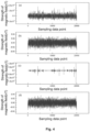
- Fig. 5 is a diagram of output results of three channels of a fluxgate in an experiment using an automobile to simulate magnetic noises of engines of an aircraft and avionics according to an embodiment of the present disclosure.
- Fig. 6 is error curves of three types of magnetic interference and a total magnetic interference in an experiment using an automobile to simulate magnetic noises of engines of an aircraft and avionics according to an embodiment of the present disclosure.
- Data of a fluxgate magnetometer in three directions is processed according to a method of acquiring a magnetic noise existing in an environmental background field to obtain errors ⁇ T, ⁇ V and ⁇ L of measured values of the fluxgate in the three directions, and results of ⁇ T, ⁇ V and ⁇ L from which direct current components are removed are shown in (a), (b) and (c) in Fig. 5 respectively.
- Error curves of three types of magnetic interference and a total magnetic interference caused by an aeromagnetic flight platform and a background field in an observation area during an exploration process are obtained according to the formulas (23), (11), (15) and (19) and are shown in Fig. 6 , wherein (a) is the error curve of the constant magnetic interference, (b) is the error curve of the induced magnetic interference, (c) is the error curve of the eddy current magnetic interference, and (d) is the error curve of the total magnetic interference.
- the fluctuation signal is mainly caused by automatic gear shifting of a gearbox of a SUV, and belongs to a sudden signal.
- Table 2 shows standard deviations and FOM values of the three types of magnetic interference fields and the total magnetic interference field in an exploration mode, and standard deviations and FOMs of different magnetic interference fields are calculated from the curves shown in Fig. 6 and are shown in Table 2.
- Table 2 Standard deviations and FOMs of different magnetic interference fields in the exploration mode Type Standard deviation (nT) FOM(nT) Constant magnetic interference 5.66 ⁇ 10 -6 9.92 ⁇ 10 -5 Induced magnetic interference 0.49 6.76
- Eddy current magnetic interference 2.83 ⁇ 10 -4 1.26 ⁇ 10 -2 Total magnetic interference field 0.49 6.76
- step S106 it is determined, according to the upper limit of the error of the magnetic noise, whether the environmental background field and the aeromagnetic flight platform are suitable for an aeromagnetic survey flight, and if so, a calibration flight is performed to acquire a compensation coefficient.
- the calculated upper limit of the aeromagnetic compensation is less than a lower limit of accuracy of the aeromagnetic experiments, it is determined whether the environmental background field and the flight platform satisfy the aeromagnetic experiments. Specifically, high-accuracy aeromagnetic experiments usually require a FOM to be less than 1nT. If the calculated upper limit of the aeromagnetic compensation is greater than 1nT, it proves that an area or an aircraft in flight is not suitable for aeromagnetic experiments under this accuracy.
- the method for acquiring the compensation coefficients comprises: performing a calibration flight, and acquiring an attitude term according to outputs of the three-axis fluxgate magnetometer in three directions and strength of a geomagnetic field; acquiring an interference magnetic field of the aircraft at the optically pumped magnetometer according to data of the calibration flight; and calculating the compensation coefficients using the attitude term and the interference magnetic field.
- the attitude term in the formula (24) is obtained by using the outputs of the three-axis fluxgate magnetometer in the three directions and the strength of the geomagnetic field, and H d is magnetic interference data which is derived through the curves obtained by the optically pumped magnetometer during the calibration flight.
- step S108 data of an attitude term is acquired by performing an actual flight, an interference magnetic field is calculated by the data of the attitude term and the compensation coefficient acquired during the calibration flight, and magnetic compensation is performed.
- attitude information of the aircraft with respect to the geomagnetic field is measured by using the three-axis magnetometer. It may be known from the formulas (8) to (10) that the corresponding attitude term may be determined according to the direction cosines and the geomagnetic field, and therefore corresponding 18 attitude terms may be obtained by the outputs of the three-axis magnetometer and the value of the geomagnetic field, and then the interference magnetic field of the aircraft is obtained by using the 18 attitude terms and the compensation coefficients obtained during the calibration flight.
- the upper limit of the aeromagnetic compensation in the formula (25) is determined by a contribution component A M C of the fluxgate.
- the magnetic compensation method based on an aeromagnetic compensation error model is not limited to the specific methods mentioned in the embodiments, and those skilled in the art may simply make changes or substitutions thereto, for example: the aeromagnetic compensation model does not necessarily comprise all 18 items as selected items to be used, and may only cover some of the 18 items.
- the present disclosure provides a magnetic compensation method based on an aeromagnetic compensation error model.
- a model error caused by an environmental background magnetic noise engines of an aircraft and avionics is firstly calculated to determine an upper limit of a background error, so as to determine whether a magnetic noise level in an area or of the aircraft is suitable for an aeromagnetic survey flight.
- a method for calculating an upper limit of magnetic compensation which may estimate an environmental background field in an exploration area before an aeromagnetic compensation calibration flight is performed, and magnetic characteristics of an aeromagnetic flight platform are estimated effectively in advance, to determine in advance whether the exploration area and an aeromagnetic flight platform are suitable for aeromagnetic exploration, which provides a theoretical basis for the selection and construction of the platform, and avoids occurrence of an invalid flight.
- the magnetic compensation method based on an aeromagnetic compensation error model according to the present disclosure further comprises other commonly-used methods and steps. Since the other commonly-used methods and steps have nothing to do with the innovation of the present disclosure, they will not be repeated here.
Landscapes
- Life Sciences & Earth Sciences (AREA)
- Engineering & Computer Science (AREA)
- Remote Sensing (AREA)
- Environmental & Geological Engineering (AREA)
- Geology (AREA)
- Physics & Mathematics (AREA)
- General Life Sciences & Earth Sciences (AREA)
- General Physics & Mathematics (AREA)
- Geophysics (AREA)
- Aviation & Aerospace Engineering (AREA)
- Measuring Magnetic Variables (AREA)
- Geophysics And Detection Of Objects (AREA)
Claims (7)
- Ein Magnetkompensationsverfahren basierend auf einem aeromagnetischen Kompensationsfehlermodell für geophysikalische Erkundung, das folgende Schritte aufweist:Erfassen eines Gesamtmagnetinterferenzfehlers unter Verwendung des aeromagnetischen Kompensationsfehlermodells vor einem aeromagnetischen Flug, wobei der Gesamtmagnetinterferenzfehler sowohl durch ein Umgebungshintergrundfeld in einem Erkundungsbereich als auch durch eine aeromagnetische Flugplattform verursacht wird;Bestimmen (S106), gemäß dem Gesamtmagnetinterferenzfehler, ob das Umgebungshintergrundfeld und die aeromagnetische Flugplattform für einen aeromagnetischen Vermessungsflug geeignet sind, und wenn dies der Fall ist, Durchführen eines Kalibrierungsfluges, um einen Kompensationskoeffizienten eines Interferenzmagnetfeldes zu erfassen; undErfassen (S108) von Daten eines Lageterms durch Durchführen eines tatsächlichen Fluges, Berechnen eines Interferenzmagnetfeldes durch die Daten des Lageterms und den Kompensationskoeffizienten, die während des Kalibrierungsfluges erfasst werden, und Durchführen einer Magnetkompensation mit Daten, die durch ein optisch gepumptes Magnetometer gemessen werden;wobei das aeromagnetische Kompensationsfehlermodell durch Erfassen verschiedener Interferenzmagnetfelder und Erfassen von Fehlern von Magnetinterferenzen, die den Interferenzmagnetfeldern entsprechen, basierend auf Ausdrücken der jeweiligen Interferenzmagnetfelder erstellt wird, um einen Gesamtmagnetinterferenzfehler zu erfassen;wobei das Durchführen eines Kalibrierungsfluges, um einen Kompensationskoeffizienten eines Interferenzmagnetfeldes zu erfassen, folgende Schritte aufweist:Durchführen des Kalibrierungsfluges und Erfassen eines Lageterms gemäß Ausgaben eines dreiachsigen Fluxgate-Magnetometers in drei Richtungen und einer Stärke eines geomagnetischen Feldes;Erfassen eines Interferenzmagnetfeldes eines Flugzeugs an einem optisch gepumpten Magnetometer gemäß Daten des Kalibrierungsfluges; undBerechnen des Kompensationskoeffizienten unter Verwendung des Lageterms und des Interferenzmagnetfeldes,wobei der Kompensationskoeffizient Folgendes erfüllt:
 wobei C ein Spaltenvektor ist, der aus dem Kompensationskoeffizienten besteht; A eine Matrix ist, die aus diskreten Zeitreihen des Lageterms besteht; Hd ein Spaltenvektor ist, der aus diskreten Zeitreihen von Hd (t) besteht; und Hd (t) eine Stärke eines Interferenzmagnetfelds des Flugzeugs zum Zeitpunkt t ist; undwobei ein Magnetfeld nach dem Durchführen der Magnetkompensation Folgendes erfüllt:
 wobei HC das Magnetfeld ist, nachdem die Magnetkompensation durchgeführt ist; HM Daten sind, die durch das optisch gepumpte Magnetometer gemessen werden; und AM ein Lageterm ist, der während des tatsächlichen Flugs erfasst wird und gemäß gemessenen Daten eines Fluxgate berechnet wird.
 - Das Magnetkompensationsverfahren gemäß Anspruch 1, wobei die verschiedenen Interferenzmagnetfelder folgende Merkmale aufweisen: ein konstantes Interferenzmagnetfeld, ein induziertes Interferenzmagnetfeld und ein Wirbelstrominterferenzmagnetfeld, und der Gesamtmagnetinterferenzfehler in dem aeromagnetischen Kompensationsfehlermodell Folgendes erfüllt:


- Das Magnetkompensationsverfahren gemäß Anspruch 2, wobeidas konstante Interferenzmagnetfeld HPERM(t) Folgendes erfüllt:
 das induzierte Interferenzmagnetfeld HIND(t) Folgendes erfüllt:
 das Wirbelstrominterferenzmagnetfeld HEDDY (t) Folgendes erfüllt:
 wobei ci,i = 1,···,3 ein Kompensationskoeffizient des konstanten Interferenzmagnetfelds ist; Ai ,i = 1,···,3 ein Lageterm ist, der aus Richtungskosiunssen besteht; He (t) eine Stärke eines geomagnetischen Feldes ist, ci,i = 4,···,9 ein Kompensationskoeffizient des induzierten Interferenzmagnetfelds ist; Ai,i = 4,···,9 ein Lageterm ist, der aus entsprechenden Richtungskosinussen und He (t) besteht;


- Das Magnetkompensationsverfahren gemäß Anspruch 3, bei dem die Richtungskosinusse u 1, u 2 und u 3 Folgendes erfüllen:


- Das Magnetkompensationsverfahren gemäß Anspruch 1, wobei das Bestimmen, gemäß dem Gesamtmagnetinterferenzfehler, ob das Umgebungshintergrundfeld und die aeromagnetische Flugplattform für einen aeromagnetischen Vermessungsflug geeignet sind, folgende Schritte aufweist:
Bestimmen, ob das Umgebungshintergrundfeld und die aeromagnetische Flugplattform ein aeromagnetisches Experiment erfüllen, gemäß dem, ob eine berechnete Obergrenze der aeromagnetischen Kompensation kleiner als eine Untergrenze der Genauigkeit für das aeromagnetische Experiment ist, und wenn die Obergrenze der aeromagnetischen Kompensation kleiner als die Untergrenze der Genauigkeit für das aeromagnetische Experiment ist, Bestimmen, dass dieselbe für den aeromagnetischen Vermessungsflug geeignet ist; andernfalls Bestimmen, dass dieselbe nicht für den aeromagnetischen Vermessungsflug geeignet ist. - Das Magnetkompensationsverfahren gemäß Anspruch 1, wobei das Interferenzmagnetfeld des Flugzeugs an dem optisch gepumpten Magnetometer Folgendes erfüllt:
 wobei Hd (t) das Interferenzmagnetfeld des Flugzeugs an dem optisch gepumpten Magnetometer ist; HPERM (t) ein konstantes Interferenzmagnetfeld ist; HEDDY (t) ein induziertes Interferenzmagnetfeld ist; und HEDDY (t) ein Wirbelstrominterferenzmagnetfeld ist; unddas Interferenzmagnetfeld 18 Elemente oder einige der 18 Elemente aufweist.
 - Das Magnetkompensationsverfahren gemäß einem der Ansprüche 1 bis 6, wobeidas Erfassen des Gesamtmagnetinterferenzfehlers, der durch das Umgebungshintergrundfeld in dem Erkundungsbereich verursacht wird, folgende Schritte aufweist: Messen des Umgebungshintergrundmagnetfelds an einem bestimmten Punkt in dem zu erkundenden Bereich in einem Zustand ohne ein Erkundungsflugzeug, und Erfassen des Gesamtmagnetinterferenzfehlers, der durch das Umgebungshintergrundfeld verursacht wird, unter Verwendung des aeromagnetischen Kompensationsfehlermodells; unddas Erfassen des Gesamtmagnetinterferenzfehlers, der durch die aeromagnetische Flugplattform verursacht wird, folgende Schritte aufweist: Messen eines Magnetfelds des Rauschens in einem Betriebszustand, wobei in dem Betriebszustand Vorrichtungen wie etwa Triebwerke und Avionik eines Flugzeugs während eines Erkundungsbetriebs eingeschaltet sind, und Erfassen des Gesamtmagnetinterferenzfehlers, der durch die aeromagnetische Flugplattform verursacht wird, unter Verwendung des aeromagnetischen Kompensationsfehlermodells.
Applications Claiming Priority (1)
| Application Number | Priority Date | Filing Date | Title |
|---|---|---|---|
| PCT/CN2017/104775 WO2019061403A1 (zh) | 2017-09-30 | 2017-09-30 | 基于航磁补偿误差模型的磁补偿方法 |
Publications (3)
| Publication Number | Publication Date |
|---|---|
| EP3690491A1 EP3690491A1 (de) | 2020-08-05 |
| EP3690491A4 EP3690491A4 (de) | 2021-06-30 |
| EP3690491B1 true EP3690491B1 (de) | 2025-03-26 |
Family
ID=65902278
Family Applications (1)
| Application Number | Title | Priority Date | Filing Date |
|---|---|---|---|
| EP17926970.9A Active EP3690491B1 (de) | 2017-09-30 | 2017-09-30 | Magnetisches kompensationsverfahren auf der grundlage eines aeromagnetischen kompensationskorrekturmodells |
Country Status (4)
| Country | Link |
|---|---|
| US (1) | US11506811B2 (de) |
| EP (1) | EP3690491B1 (de) |
| CN (1) | CN111433634B (de) |
| WO (1) | WO2019061403A1 (de) |
Families Citing this family (32)
| Publication number | Priority date | Publication date | Assignee | Title |
|---|---|---|---|---|
| CN110824569B (zh) * | 2019-11-15 | 2021-04-09 | 中国科学院电子学研究所 | 基于差分进化最优化算法的航磁补偿方法 |
| CN112347625B (zh) * | 2020-10-27 | 2023-03-10 | 中国人民解放军海军工程大学 | 一种飞行器载体的磁干扰补偿方法 |
| CN112284377A (zh) * | 2020-10-27 | 2021-01-29 | 中国人民解放军海军工程大学 | 一种应用于飞行器的地磁场测量系统及方法 |
| CN112393745B (zh) * | 2020-11-18 | 2022-09-09 | 北京自动化控制设备研究所 | 磁浮标的航向误差在线补偿方法 |
| CN112649882B (zh) * | 2020-12-08 | 2022-07-15 | 北京自动化控制设备研究所 | 低频磁信号增强方法及使用其的航空磁测系统 |
| CN112858960B (zh) * | 2021-02-28 | 2022-07-22 | 哈尔滨工业大学 | 一种飞机尾杆振动引起的磁干扰的补偿方法及装置 |
| CN112858959B (zh) * | 2021-02-28 | 2023-01-17 | 哈尔滨工业大学 | 一种机载电子设备引起的磁干扰补偿方法及装置 |
| CN113049004A (zh) * | 2021-02-28 | 2021-06-29 | 哈尔滨工业大学 | 一种航磁补偿校准质量的自动评估方法及装置 |
| CN113093296B (zh) * | 2021-04-15 | 2023-09-05 | 成都纵横自动化技术股份有限公司 | 一种航磁测量方法及相关组件 |
| CN113281822A (zh) * | 2021-04-29 | 2021-08-20 | 陕西飞机工业有限责任公司 | 一种飞行器磁背景自动补偿方法 |
| CN113281824B (zh) * | 2021-05-19 | 2022-03-25 | 北京大学 | 一种考虑飞机非刚性以及极化电流因素的航空磁补偿方法 |
| CN113625349B (zh) * | 2021-06-23 | 2023-12-12 | 北京航天控制仪器研究所 | 未爆弹空中磁法探测系统及方法 |
| CN113534292B (zh) * | 2021-07-09 | 2022-12-27 | 吉林大学 | 一种基于遗忘因子rls的小信号模型航磁补偿方法 |
| CN114578439B (zh) * | 2021-12-27 | 2024-09-10 | 北京自动化控制设备研究所 | 磁补偿系数自适应优化方法及系统 |
| CN115016016B (zh) * | 2022-06-02 | 2025-05-09 | 杭州电子科技大学 | 一种三分量磁传感器本体磁性误差补偿方法 |
| CN115048962B (zh) * | 2022-06-16 | 2025-12-23 | 中国船舶重工集团公司第七一五研究所 | 一种大平面测磁系统中的信号处理方法 |
| CN115453638B (zh) * | 2022-08-26 | 2024-09-13 | 中国地质大学(武汉) | 一种航磁补偿负面效应综合抑制方法 |
| CN115480316B (zh) * | 2022-10-01 | 2025-01-17 | 北京卫星信息工程研究所 | 一种基于小信号模型的矢量磁场传感器航磁补偿方法 |
| CN115826064A (zh) * | 2022-11-14 | 2023-03-21 | 北京大学 | 基于双机多磁传感器的航空磁干扰抑制方法、装置及设备 |
| CN115905773A (zh) * | 2022-12-14 | 2023-04-04 | 南京理工大学 | 基于hls工具的在线载体磁补偿方法 |
| CN115980638A (zh) * | 2022-12-29 | 2023-04-18 | 上海航天控制技术研究所 | 一种利用磁强计标定星体内部磁场干扰量的方法 |
| CN117031564B (zh) * | 2023-07-25 | 2025-09-12 | 中国地质大学(武汉) | 一种针对多重共线性抑制的航磁补偿优化方法及系统 |
| CN117031364B (zh) * | 2023-10-10 | 2023-12-12 | 西南交通大学 | 一种多旋翼无人机动态误差补偿及降噪方法 |
| CN118332236B (zh) * | 2024-05-15 | 2024-10-11 | 中国自然资源航空物探遥感中心 | 一种航磁总场的补偿方法及补偿装置 |
| CN118393589B (zh) * | 2024-06-27 | 2024-08-30 | 西北工业大学 | 基于递推奇异值分解的磁传感器干扰补偿方法 |
| CN118938331B (zh) * | 2024-08-13 | 2025-10-28 | 中国地质大学(武汉) | 一种基于神经网络的航磁补偿方法、设备及存储介质 |
| CN119395781B (zh) * | 2024-09-27 | 2025-09-02 | 中国船舶集团有限公司第七一九研究所 | 一种基于粒子群优化算法的地磁矢量测量误差补偿方法 |
| CN119537808B (zh) * | 2024-11-15 | 2025-08-12 | 中科飞特(山东)科技有限公司 | 一种用于航磁测量的高精度磁测数据处理方法 |
| CN119937037B (zh) * | 2024-12-13 | 2025-10-14 | 中国人民解放军国防科技大学 | 考虑地磁变化的演化式航磁补偿方法、设备及介质 |
| CN120255568B (zh) * | 2025-06-04 | 2025-08-08 | 南京理工大学 | 一种基于磁张量的载体干扰空中定点补偿方法 |
| US12422503B1 (en) * | 2025-06-09 | 2025-09-23 | Mach Industries Inc. | Vehicle magnetometer calibration system |
| CN121300484B (zh) * | 2025-10-27 | 2026-04-10 | 中国自然资源航空物探遥感中心 | 基于改进型卡尔曼滤波的无人直升机磁干扰实时补偿方法及系统 |
Family Cites Families (18)
| Publication number | Priority date | Publication date | Assignee | Title |
|---|---|---|---|---|
| US5182514A (en) | 1974-11-19 | 1993-01-26 | Texas Instruments Incorporated | Automatic compensator for an airborne magnetic anomaly detector |
| US6130534A (en) | 1998-03-10 | 2000-10-10 | Chung Shan Institute Of Science And Technology | Method of calibrating a three-axis magnetometer |
| US6765383B1 (en) * | 2001-12-26 | 2004-07-20 | Anthony R. Barringer | Magnetotelluric geophysical survey system using an airborne survey bird |
| US7262601B2 (en) * | 2002-02-12 | 2007-08-28 | Bhp Billiton Innovation Pty Ltd | Aircraft equipped for airborne vector magnetic exploration surveys |
| AU2002951919A0 (en) * | 2002-10-04 | 2002-10-24 | Bhp Billiton Innovation Pty Ltd | Vector magnetic data processing |
| US20090284258A1 (en) | 2008-05-14 | 2009-11-19 | Geotech Airborne Limited | Airborne geophysical survey using airship |
| US8717009B2 (en) * | 2010-10-06 | 2014-05-06 | Apple Inc. | Magnetometer calibration |
| CN104062687B (zh) * | 2014-06-12 | 2018-08-10 | 中国航空无线电电子研究所 | 一种空地一体的地磁场联合观测方法及系统 |
| US9671226B2 (en) * | 2014-12-17 | 2017-06-06 | Honeywell International Inc. | Magnetic sensor calibration for aircraft |
| CN104678448B (zh) * | 2015-03-02 | 2017-07-14 | 中国人民解放军国防科学技术大学 | 基于激光束和反光镜的磁干扰分量补偿方法 |
| US10725123B2 (en) * | 2015-07-21 | 2020-07-28 | Israel Aerospace Industries Ltd. | Gradiometer system and method |
| CN105425304B (zh) | 2015-11-03 | 2017-09-15 | 哈尔滨工业大学 | 一种飞机航磁干扰的补偿方法 |
| CN105301666B (zh) | 2015-11-05 | 2017-09-26 | 哈尔滨工业大学 | 一种航磁干扰补偿系数的自适应调整方法 |
| CN105676302A (zh) * | 2015-11-12 | 2016-06-15 | 东南大学 | 一种基于改进最小二乘法的磁力仪随机噪声误差补偿方法 |
| CN106707352B (zh) * | 2016-11-28 | 2018-10-12 | 中国科学院电子学研究所 | 一种基于ε-SVR算法的航磁梯度干扰的去除方法 |
| CN106959471B (zh) * | 2017-04-21 | 2018-10-02 | 中国科学院电子学研究所 | 基于非线性航磁总场梯度补偿模型的航磁补偿方法 |
| CN106842344B (zh) * | 2017-04-24 | 2018-10-12 | 中国科学院电子学研究所 | 基于前馈网络的无人机航磁全轴梯度磁干扰补偿的方法 |
| CN107356978B (zh) | 2017-07-11 | 2019-03-01 | 中国科学院电子学研究所 | 基于主成分分析的航磁补偿方法 |
-
2017
- 2017-09-30 WO PCT/CN2017/104775 patent/WO2019061403A1/zh not_active Ceased
- 2017-09-30 US US16/652,333 patent/US11506811B2/en active Active
- 2017-09-30 EP EP17926970.9A patent/EP3690491B1/de active Active
- 2017-09-30 CN CN201780095496.7A patent/CN111433634B/zh active Active
Also Published As
| Publication number | Publication date |
|---|---|
| EP3690491A4 (de) | 2021-06-30 |
| US20200301040A1 (en) | 2020-09-24 |
| US11506811B2 (en) | 2022-11-22 |
| CN111433634A (zh) | 2020-07-17 |
| EP3690491A1 (de) | 2020-08-05 |
| CN111433634B (zh) | 2023-11-03 |
| WO2019061403A1 (zh) | 2019-04-04 |
Similar Documents
| Publication | Publication Date | Title |
|---|---|---|
| EP3690491A1 (de) | Magnetisches kompensationsverfahren auf der grundlage eines aeromagnetischen kompensationskorrekturmodells | |
| CA2475804C (en) | Airborne vector magnetic surveys | |
| CN109541704B (zh) | 一种三轴磁通门航磁测量系统及矫正补偿方法 | |
| Dou et al. | An aeromagnetic compensation coefficient-estimating method robust to geomagnetic gradient | |
| Noriega | Aeromagnetic compensation in gradiometry—Performance, model stability, and robustness | |
| CN106353824B (zh) | 航空磁通门磁梯度张量仪的系统校正及磁干扰补偿融合方法 | |
| US9470550B2 (en) | Method of calibrating a heading reference system | |
| US20170299761A1 (en) | Air-ground integrated earth magnetic field combined observation method and system | |
| CN105509737B (zh) | 一种不受地磁变化影响的航空运动平台磁干扰补偿方法 | |
| CN110187393B (zh) | 一种基于广义回归神经网络的航磁补偿方法 | |
| CN115524762B (zh) | 基于三维亥姆赫兹线圈的地磁矢量测量系统补偿方法 | |
| CN114184988A (zh) | 包含补偿平台电流磁干扰的航磁补偿方法及其装置 | |
| CN114325848A (zh) | 补偿系数自适应修正的航空磁干扰补偿方法及其装置 | |
| Mu et al. | Small signal magnetic compensation method for UAV-borne vector magnetometer system | |
| US11343642B2 (en) | Method for estimating the harmonization values of a magnetometer installed in a mobile machine, associated device and computer program | |
| Calou et al. | Airborne magnetic surveying with a drone and determination of the total magnetization of a dipole | |
| CN118426063B (zh) | 抑制地质磁干扰的航空磁补偿方法及系统 | |
| US10466081B2 (en) | Iterative method of determining a bias of a sensor for measuring a substantially continuous physical vector field | |
| Zhang et al. | A simplified aeromagnetic compensation model for low magnetism UAV platform | |
| CN108919368B (zh) | 一种用于消除微小卫星剩磁干扰的系统及方法 | |
| Yan et al. | A compensation method in magnetic distortion through regularized inverse problems | |
| Guo et al. | An improved magnetic compensation algorithm for swing noise | |
| Zhou et al. | A method for aircraft magnetic interference compensation based on small signal model and LMS algorithm | |
| Yin | Compensation for aircraft effects of magnetic tensor gradiometer with nonlinear least square method | |
| CA2501121C (en) | Vector magnetic data processing |
Legal Events
| Date | Code | Title | Description |
|---|---|---|---|
| STAA | Information on the status of an ep patent application or granted ep patent |
Free format text: STATUS: THE INTERNATIONAL PUBLICATION HAS BEEN MADE |
|
| PUAI | Public reference made under article 153(3) epc to a published international application that has entered the european phase |
Free format text: ORIGINAL CODE: 0009012 |
|
| STAA | Information on the status of an ep patent application or granted ep patent |
Free format text: STATUS: REQUEST FOR EXAMINATION WAS MADE |
|
| 17P | Request for examination filed |
Effective date: 20200429 |
|
| AK | Designated contracting states |
Kind code of ref document: A1 Designated state(s): AL AT BE BG CH CY CZ DE DK EE ES FI FR GB GR HR HU IE IS IT LI LT LU LV MC MK MT NL NO PL PT RO RS SE SI SK SM TR |
|
| AX | Request for extension of the european patent |
Extension state: BA ME |
|
| DAV | Request for validation of the european patent (deleted) | ||
| DAX | Request for extension of the european patent (deleted) | ||
| A4 | Supplementary search report drawn up and despatched |
Effective date: 20210531 |
|
| RIC1 | Information provided on ipc code assigned before grant |
Ipc: G01V 3/38 20060101AFI20210525BHEP Ipc: G01V 3/40 20060101ALI20210525BHEP Ipc: G01V 3/16 20060101ALI20210525BHEP |
|
| STAA | Information on the status of an ep patent application or granted ep patent |
Free format text: STATUS: EXAMINATION IS IN PROGRESS |
|
| 17Q | First examination report despatched |
Effective date: 20230517 |
|
| GRAP | Despatch of communication of intention to grant a patent |
Free format text: ORIGINAL CODE: EPIDOSNIGR1 |
|
| STAA | Information on the status of an ep patent application or granted ep patent |
Free format text: STATUS: GRANT OF PATENT IS INTENDED |
|
| RIC1 | Information provided on ipc code assigned before grant |
Ipc: G01V 3/16 20060101ALI20240913BHEP Ipc: G01V 3/38 20060101AFI20240913BHEP |
|
| INTG | Intention to grant announced |
Effective date: 20240927 |
|
| GRAS | Grant fee paid |
Free format text: ORIGINAL CODE: EPIDOSNIGR3 |
|
| GRAA | (expected) grant |
Free format text: ORIGINAL CODE: 0009210 |
|
| STAA | Information on the status of an ep patent application or granted ep patent |
Free format text: STATUS: THE PATENT HAS BEEN GRANTED |
|
| RAP3 | Party data changed (applicant data changed or rights of an application transferred) |
Owner name: AEROSPACE INFORMATION RESEARCH INSTITUTE,CHINESE ACADEMY OF SCIENCES |
|
| AK | Designated contracting states |
Kind code of ref document: B1 Designated state(s): AL AT BE BG CH CY CZ DE DK EE ES FI FR GB GR HR HU IE IS IT LI LT LU LV MC MK MT NL NO PL PT RO RS SE SI SK SM TR |
|
| REG | Reference to a national code |
Ref country code: GB Ref legal event code: FG4D |
|
| REG | Reference to a national code |
Ref country code: CH Ref legal event code: EP |
|
| P01 | Opt-out of the competence of the unified patent court (upc) registered |
Free format text: CASE NUMBER: APP_9616/2025 Effective date: 20250226 |
|
| REG | Reference to a national code |
Ref country code: DE Ref legal event code: R096 Ref document number: 602017088600 Country of ref document: DE |
|
| REG | Reference to a national code |
Ref country code: IE Ref legal event code: FG4D |
|
| PG25 | Lapsed in a contracting state [announced via postgrant information from national office to epo] |
Ref country code: RS Free format text: LAPSE BECAUSE OF FAILURE TO SUBMIT A TRANSLATION OF THE DESCRIPTION OR TO PAY THE FEE WITHIN THE PRESCRIBED TIME-LIMIT Effective date: 20250626 |
|
| PG25 | Lapsed in a contracting state [announced via postgrant information from national office to epo] |
Ref country code: FI Free format text: LAPSE BECAUSE OF FAILURE TO SUBMIT A TRANSLATION OF THE DESCRIPTION OR TO PAY THE FEE WITHIN THE PRESCRIBED TIME-LIMIT Effective date: 20250326 |
|
| REG | Reference to a national code |
Ref country code: LT Ref legal event code: MG9D |
|
| PG25 | Lapsed in a contracting state [announced via postgrant information from national office to epo] |
Ref country code: NO Free format text: LAPSE BECAUSE OF FAILURE TO SUBMIT A TRANSLATION OF THE DESCRIPTION OR TO PAY THE FEE WITHIN THE PRESCRIBED TIME-LIMIT Effective date: 20250626 |
|
| PG25 | Lapsed in a contracting state [announced via postgrant information from national office to epo] |
Ref country code: HR Free format text: LAPSE BECAUSE OF FAILURE TO SUBMIT A TRANSLATION OF THE DESCRIPTION OR TO PAY THE FEE WITHIN THE PRESCRIBED TIME-LIMIT Effective date: 20250326 |
|
| PG25 | Lapsed in a contracting state [announced via postgrant information from national office to epo] |
Ref country code: LV Free format text: LAPSE BECAUSE OF FAILURE TO SUBMIT A TRANSLATION OF THE DESCRIPTION OR TO PAY THE FEE WITHIN THE PRESCRIBED TIME-LIMIT Effective date: 20250326 |
|
| PG25 | Lapsed in a contracting state [announced via postgrant information from national office to epo] |
Ref country code: BG Free format text: LAPSE BECAUSE OF FAILURE TO SUBMIT A TRANSLATION OF THE DESCRIPTION OR TO PAY THE FEE WITHIN THE PRESCRIBED TIME-LIMIT Effective date: 20250326 Ref country code: GR Free format text: LAPSE BECAUSE OF FAILURE TO SUBMIT A TRANSLATION OF THE DESCRIPTION OR TO PAY THE FEE WITHIN THE PRESCRIBED TIME-LIMIT Effective date: 20250627 |
|
| REG | Reference to a national code |
Ref country code: NL Ref legal event code: MP Effective date: 20250326 |
|
| PG25 | Lapsed in a contracting state [announced via postgrant information from national office to epo] |
Ref country code: NL Free format text: LAPSE BECAUSE OF FAILURE TO SUBMIT A TRANSLATION OF THE DESCRIPTION OR TO PAY THE FEE WITHIN THE PRESCRIBED TIME-LIMIT Effective date: 20250326 |
|
| PG25 | Lapsed in a contracting state [announced via postgrant information from national office to epo] |
Ref country code: SE Free format text: LAPSE BECAUSE OF FAILURE TO SUBMIT A TRANSLATION OF THE DESCRIPTION OR TO PAY THE FEE WITHIN THE PRESCRIBED TIME-LIMIT Effective date: 20250326 |
|
| REG | Reference to a national code |
Ref country code: AT Ref legal event code: MK05 Ref document number: 1779471 Country of ref document: AT Kind code of ref document: T Effective date: 20250326 |
|
| PG25 | Lapsed in a contracting state [announced via postgrant information from national office to epo] |
Ref country code: SM Free format text: LAPSE BECAUSE OF FAILURE TO SUBMIT A TRANSLATION OF THE DESCRIPTION OR TO PAY THE FEE WITHIN THE PRESCRIBED TIME-LIMIT Effective date: 20250326 |
|
| PG25 | Lapsed in a contracting state [announced via postgrant information from national office to epo] |
Ref country code: PT Free format text: LAPSE BECAUSE OF FAILURE TO SUBMIT A TRANSLATION OF THE DESCRIPTION OR TO PAY THE FEE WITHIN THE PRESCRIBED TIME-LIMIT Effective date: 20250728 Ref country code: ES Free format text: LAPSE BECAUSE OF FAILURE TO SUBMIT A TRANSLATION OF THE DESCRIPTION OR TO PAY THE FEE WITHIN THE PRESCRIBED TIME-LIMIT Effective date: 20250326 |
|
| PGFP | Annual fee paid to national office [announced via postgrant information from national office to epo] |
Ref country code: DE Payment date: 20250718 Year of fee payment: 9 |
|
| PG25 | Lapsed in a contracting state [announced via postgrant information from national office to epo] |
Ref country code: PL Free format text: LAPSE BECAUSE OF FAILURE TO SUBMIT A TRANSLATION OF THE DESCRIPTION OR TO PAY THE FEE WITHIN THE PRESCRIBED TIME-LIMIT Effective date: 20250326 Ref country code: IT Free format text: LAPSE BECAUSE OF FAILURE TO SUBMIT A TRANSLATION OF THE DESCRIPTION OR TO PAY THE FEE WITHIN THE PRESCRIBED TIME-LIMIT Effective date: 20250326 |
|
| PGFP | Annual fee paid to national office [announced via postgrant information from national office to epo] |
Ref country code: GB Payment date: 20250927 Year of fee payment: 9 |
|
| PG25 | Lapsed in a contracting state [announced via postgrant information from national office to epo] |
Ref country code: AT Free format text: LAPSE BECAUSE OF FAILURE TO SUBMIT A TRANSLATION OF THE DESCRIPTION OR TO PAY THE FEE WITHIN THE PRESCRIBED TIME-LIMIT Effective date: 20250326 |
|
| PGFP | Annual fee paid to national office [announced via postgrant information from national office to epo] |
Ref country code: FR Payment date: 20250926 Year of fee payment: 9 |
|
| PG25 | Lapsed in a contracting state [announced via postgrant information from national office to epo] |
Ref country code: EE Free format text: LAPSE BECAUSE OF FAILURE TO SUBMIT A TRANSLATION OF THE DESCRIPTION OR TO PAY THE FEE WITHIN THE PRESCRIBED TIME-LIMIT Effective date: 20250326 |
|
| PG25 | Lapsed in a contracting state [announced via postgrant information from national office to epo] |
Ref country code: RO Free format text: LAPSE BECAUSE OF FAILURE TO SUBMIT A TRANSLATION OF THE DESCRIPTION OR TO PAY THE FEE WITHIN THE PRESCRIBED TIME-LIMIT Effective date: 20250326 |
|
| PG25 | Lapsed in a contracting state [announced via postgrant information from national office to epo] |
Ref country code: SK Free format text: LAPSE BECAUSE OF FAILURE TO SUBMIT A TRANSLATION OF THE DESCRIPTION OR TO PAY THE FEE WITHIN THE PRESCRIBED TIME-LIMIT Effective date: 20250326 |
|
| PG25 | Lapsed in a contracting state [announced via postgrant information from national office to epo] |
Ref country code: IS Free format text: LAPSE BECAUSE OF FAILURE TO SUBMIT A TRANSLATION OF THE DESCRIPTION OR TO PAY THE FEE WITHIN THE PRESCRIBED TIME-LIMIT Effective date: 20250726 |
|
| REG | Reference to a national code |
Ref country code: DE Ref legal event code: R097 Ref document number: 602017088600 Country of ref document: DE |
|
| PG25 | Lapsed in a contracting state [announced via postgrant information from national office to epo] |
Ref country code: DK Free format text: LAPSE BECAUSE OF FAILURE TO SUBMIT A TRANSLATION OF THE DESCRIPTION OR TO PAY THE FEE WITHIN THE PRESCRIBED TIME-LIMIT Effective date: 20250326 |
|
| PG25 | Lapsed in a contracting state [announced via postgrant information from national office to epo] |
Ref country code: CZ Free format text: LAPSE BECAUSE OF FAILURE TO SUBMIT A TRANSLATION OF THE DESCRIPTION OR TO PAY THE FEE WITHIN THE PRESCRIBED TIME-LIMIT Effective date: 20250326 |
|
| PLBE | No opposition filed within time limit |
Free format text: ORIGINAL CODE: 0009261 |
|
| STAA | Information on the status of an ep patent application or granted ep patent |
Free format text: STATUS: NO OPPOSITION FILED WITHIN TIME LIMIT |
|
| REG | Reference to a national code |
Ref country code: CH Ref legal event code: L10 Free format text: ST27 STATUS EVENT CODE: U-0-0-L10-L00 (AS PROVIDED BY THE NATIONAL OFFICE) Effective date: 20260211 |
|
| 26N | No opposition filed |
Effective date: 20260105 |
|
| REG | Reference to a national code |
Ref country code: CH Ref legal event code: H13 Free format text: ST27 STATUS EVENT CODE: U-0-0-H10-H13 (AS PROVIDED BY THE NATIONAL OFFICE) Effective date: 20260425 |