EP3690361A1 - Oil separator and air conditioner with same - Google Patents
Oil separator and air conditioner with same Download PDFInfo
- Publication number
- EP3690361A1 EP3690361A1 EP17926760.4A EP17926760A EP3690361A1 EP 3690361 A1 EP3690361 A1 EP 3690361A1 EP 17926760 A EP17926760 A EP 17926760A EP 3690361 A1 EP3690361 A1 EP 3690361A1
- Authority
- EP
- European Patent Office
- Prior art keywords
- oil
- refrigerant
- groove
- oil separator
- separation container
- Prior art date
- Legal status (The legal status is an assumption and is not a legal conclusion. Google has not performed a legal analysis and makes no representation as to the accuracy of the status listed.)
- Granted
Links
Images








Classifications
-
- F—MECHANICAL ENGINEERING; LIGHTING; HEATING; WEAPONS; BLASTING
- F25—REFRIGERATION OR COOLING; COMBINED HEATING AND REFRIGERATION SYSTEMS; HEAT PUMP SYSTEMS; MANUFACTURE OR STORAGE OF ICE; LIQUEFACTION SOLIDIFICATION OF GASES
- F25B—REFRIGERATION MACHINES, PLANTS OR SYSTEMS; COMBINED HEATING AND REFRIGERATION SYSTEMS; HEAT PUMP SYSTEMS
- F25B43/00—Arrangements for separating or purifying gases or liquids; Arrangements for vaporising the residuum of liquid refrigerant, e.g. by heat
- F25B43/02—Arrangements for separating or purifying gases or liquids; Arrangements for vaporising the residuum of liquid refrigerant, e.g. by heat for separating lubricants from the refrigerant
-
- F—MECHANICAL ENGINEERING; LIGHTING; HEATING; WEAPONS; BLASTING
- F25—REFRIGERATION OR COOLING; COMBINED HEATING AND REFRIGERATION SYSTEMS; HEAT PUMP SYSTEMS; MANUFACTURE OR STORAGE OF ICE; LIQUEFACTION SOLIDIFICATION OF GASES
- F25B—REFRIGERATION MACHINES, PLANTS OR SYSTEMS; COMBINED HEATING AND REFRIGERATION SYSTEMS; HEAT PUMP SYSTEMS
- F25B31/00—Compressor arrangements
- F25B31/002—Lubrication
- F25B31/004—Lubrication oil recirculating arrangements
-
- F—MECHANICAL ENGINEERING; LIGHTING; HEATING; WEAPONS; BLASTING
- F25—REFRIGERATION OR COOLING; COMBINED HEATING AND REFRIGERATION SYSTEMS; HEAT PUMP SYSTEMS; MANUFACTURE OR STORAGE OF ICE; LIQUEFACTION SOLIDIFICATION OF GASES
- F25B—REFRIGERATION MACHINES, PLANTS OR SYSTEMS; COMBINED HEATING AND REFRIGERATION SYSTEMS; HEAT PUMP SYSTEMS
- F25B2400/00—Component parts or details not otherwise provided for in this subclass
- F25B2400/02—Centrifugal separation of gas, liquid or oil
-
- F—MECHANICAL ENGINEERING; LIGHTING; HEATING; WEAPONS; BLASTING
- F25—REFRIGERATION OR COOLING; COMBINED HEATING AND REFRIGERATION SYSTEMS; HEAT PUMP SYSTEMS; MANUFACTURE OR STORAGE OF ICE; LIQUEFACTION SOLIDIFICATION OF GASES
- F25B—REFRIGERATION MACHINES, PLANTS OR SYSTEMS; COMBINED HEATING AND REFRIGERATION SYSTEMS; HEAT PUMP SYSTEMS
- F25B2400/00—Component parts or details not otherwise provided for in this subclass
- F25B2400/23—Separators
-
- F—MECHANICAL ENGINEERING; LIGHTING; HEATING; WEAPONS; BLASTING
- F25—REFRIGERATION OR COOLING; COMBINED HEATING AND REFRIGERATION SYSTEMS; HEAT PUMP SYSTEMS; MANUFACTURE OR STORAGE OF ICE; LIQUEFACTION SOLIDIFICATION OF GASES
- F25B—REFRIGERATION MACHINES, PLANTS OR SYSTEMS; COMBINED HEATING AND REFRIGERATION SYSTEMS; HEAT PUMP SYSTEMS
- F25B2500/00—Problems to be solved
- F25B2500/01—Geometry problems, e.g. for reducing size
-
- F—MECHANICAL ENGINEERING; LIGHTING; HEATING; WEAPONS; BLASTING
- F25—REFRIGERATION OR COOLING; COMBINED HEATING AND REFRIGERATION SYSTEMS; HEAT PUMP SYSTEMS; MANUFACTURE OR STORAGE OF ICE; LIQUEFACTION SOLIDIFICATION OF GASES
- F25B—REFRIGERATION MACHINES, PLANTS OR SYSTEMS; COMBINED HEATING AND REFRIGERATION SYSTEMS; HEAT PUMP SYSTEMS
- F25B2500/00—Problems to be solved
- F25B2500/17—Size reduction
Definitions
- the present invention relates to an oil separator and an air conditioner including the oil separator, and particularly to an oil separator that separates oil contained in refrigerant, and an air conditioner including the oil separator.
- An air conditioning apparatus includes an oil separator used for separating, from refrigerant, the oil (refrigeration oil) discharged together with the refrigerant from a compressor so as to return the separated oil to the compressor.
- the oil separator is required to efficiently separate the refrigeration oil from the refrigerant.
- PTL 1 proposes an oil separator for solving such problems.
- An object of the present invention is to provide an oil separator for efficiently separating refrigeration oil from refrigerant while suppressing re-dispersion of the separated refrigeration oil.
- Another object of the present invention is to provide an air conditioner including the oil separator.
- One oil separator serves as an oil separator for separating refrigeration oil contained in refrigerant from the refrigerant, and includes a separation container, an inlet pipe, an outlet pipe, an oil reservoir, a liquid passage section, and an oil return pipe.
- the separation container forms a separation chamber.
- the inlet pipe of the refrigerant communicates with the separation container.
- the outlet pipe of the refrigerant communicates with the separation container.
- the oil reservoir is provided in the separation container and configured to store the refrigeration oil.
- the liquid passage section provided with a groove is disposed inside the separation container and configured to guide the refrigeration oil contained in the refrigerant to the oil reservoir.
- the oil return pipe is attached to the separation container and communicates with the oil reservoir.
- the liquid passage section has the groove that is formed to be gradually increased in depth from an upper portion of the groove toward a lower portion of the groove.
- Another oil separator serves as an oil separator for separating refrigeration oil contained in refrigerant from the refrigerant, and includes a separation container, an inlet pipe, an outlet pipe, an impeller section, a liquid passage section, an oil reservoir, and an oil return pipe.
- the separation container forms a separation chamber.
- the inlet pipe of the refrigerant communicates with the separation container.
- the outlet pipe of the refrigerant communicates with the separation container.
- the impeller section is provided inside the separation container and has a vane configured to rotate by a flow of the refrigerant that is supplied from the inlet pipe.
- the liquid passage section is provided in the vane and provided with a groove through which the refrigeration oil contained in the refrigerant is guided.
- the oil reservoir is provided in the separation container and configured to store the refrigeration oil.
- the oil return pipe is attached to the separation container and communicates with the oil reservoir.
- the groove is provided on a wall surface of the vane so as to extend from a rotation center side of the vane toward an outer circumferential end of the vane.
- An air conditioner according to the present invention serves as an air conditioner including the above-mentioned one oil separator or another oil separator, and includes a compressor, an oil separator, a condenser, an expansion valve, and an evaporator that are connected sequentially in series by a refrigerant pipe.
- the refrigerant pipe has the inlet pipe and the outlet pipe.
- the inlet pipe connects a discharge side of the compressor and the oil separator.
- the outlet pipe connects the oil separator and the condenser.
- the oil return pipe connects the oil separator and a suction side of the compressor.
- refrigeration oil contained in refrigerant is received in a groove formed to be gradually increased in depth from an upper portion of the groove toward a lower portion thereof.
- the refrigeration oil contained in the refrigerant when refrigerant and the like flow along a vane, the refrigeration oil contained in the refrigerant is received in a groove formed in the vane. Thereby, re-dispersion of the refrigeration oil by the refrigerant and the like can be prevented, with the result that the efficiency in separating the refrigeration oil contained in the refrigerant can be enhanced while the separated refrigeration oil can be returned to a compressor.
- the efficiency in separating the refrigeration oil contained in the refrigerant can be enhanced while the separated refrigeration oil can be returned to a compressor.
- a refrigerant circuit is formed by sequentially connecting a compressor 3, an oil separator 5, a condenser 7, an expansion valve 9, and an evaporator 11 through a refrigerant pipe 13.
- the refrigerant is compressed by compressor 3 and turns into high-temperature and high-pressure gas refrigerant, which is then discharged from compressor 3.
- the discharged high-temperature and high-pressure gas refrigerant is conveyed through oil separator 5 to condenser 7.
- heat exchange is performed between the incoming refrigerant and the air supplied into condenser 7.
- the high-temperature and high-pressure gas refrigerant is condensed and turns into high-pressure liquid refrigerant.
- expansion valve 9 the high-pressure liquid refrigerant supplied from condenser 7 is turned into refrigerant in a two-phase state including low-pressure gas refrigerant and liquid refrigerant.
- the refrigerant in a two-phase state flows into evaporator 11.
- heat exchange is performed between the incoming refrigerant in a two-phase state and the air supplied into evaporator 11. By this heat exchange, the liquid refrigerant evaporates and turns into low-pressure gas refrigerant.
- the low-pressure gas refrigerant supplied from evaporator 11 flows into compressor 3, in which the low-pressure gas refrigerant is compressed into high-temperature and high-pressure gas refrigerant.
- the high-temperature and high-pressure gas refrigerant is again discharged from compressor 3 and conveyed through oil separator 5 to condenser 7. This cycle is repeated thereafter.
- air conditioner 1 the refrigeration oil contained in the refrigerant discharged from compressor 3 is separated from the refrigerant in oil separator 5.
- the separated refrigeration oil is to flow through an oil return pipe 19 so as to be returned to the suction side of compressor 3.
- oil separator 5 includes a separation container 56 that forms a separation chamber 55.
- separation container 56 is formed in an approximately circular cylindrical shape.
- Separation container 56 has a side surface portion to which an inlet pipe 15 is attached as a part of refrigerant pipe 13.
- Inlet pipe 15 is attached so as to extend in the direction approximately orthogonal to the tangential direction of the side surface portion of separation container 56.
- Inlet pipe 15 connects the discharge side of compressor 3 and oil separator 5 (separation container 56).
- Separation container 56 has an upper surface portion to which an outlet pipe 17 is attached as a part of refrigerant pipe 13. Outlet pipe 17 connects oil separator 5 (separation container 56) and condenser 7. In a lower portion of separation container 56, an oil reservoir 61 is provided. Separation container 56 has a lower surface portion to which oil return pipe 19 is attached. Oil return pipe 19 connects oil reservoir 61 and the suction side of compressor 3.
- separation container 56 has an inner wall surface provided with a liquid passage section 57 serving as a flow passage of refrigeration oil.
- Liquid passage section 57 is disposed to include a region facing the outlet port of inlet pipe 15.
- Liquid passage section 57 is provided with a groove 57a.
- groove 57a is disposed to extend in the direction of gravity toward oil reservoir 61.
- groove 57a is formed to have a depth D that is gradually increased from an upper portion of groove 57a toward a lower portion thereof. In other words, groove 57a is formed to be gradually increased in depth from the upstream side of the flow of the refrigeration oil toward the downstream side thereof.
- the refrigeration oil received in groove 57a flows by gravity through groove 57a so as to be fed into oil reservoir 61 as indicated by an arrow.
- Refrigeration oil 100 accumulated in oil reservoir 61 flows into oil return pipe 19.
- the refrigeration oil having flowed through oil return pipe 19 is fed into the suction side of compressor 3. In this way, the refrigeration oil discharged together with the refrigerant is returned to compressor 3. This operation is to be repeated thereafter while air conditioner 1 is operating.
- groove 57a formed in liquid passage section 57 and receiving the refrigeration oil contained in the refrigerant is disposed to extend toward oil reservoir 61 in the direction of gravity. Also, groove 57a is formed to be gradually increased in depth from its upper portion toward its lower portion.
- the area of contact between the refrigeration oil and groove 57a is to increase from the upper portion of groove 57a toward the lower portion thereof.
- the interfacial energy represented by the product of the area of contact and the surface tension gradually becomes larger in the negative direction from the upper portion of groove 57a toward the lower portion thereof. In other words, it means that the interfacial energy decreases.
- the refrigeration oil flows actively through groove 57a toward the lower portion of groove 57a at which the interfacial energy is smaller, so that the refrigeration oil is introduced into oil reservoir 61.
- the refrigeration oil actively flows through groove 57a accumulation of the refrigeration oil in groove 57a can be suppressed while re-dispersion of the refrigeration oil by the refrigerant discharged from inlet pipe 15 can be prevented.
- the efficiency in separating the refrigeration oil contained in the refrigerant can be enhanced while the separated refrigeration oil can be returned to the compressor.
- liquid passage section 57 may be formed in a range at least in the circumference portion of the length corresponding to the radius of inlet pipe 15 on the side wall surface of separation container 56 that faces the outlet port of inlet pipe 15. In order to reliably suppress re-dispersion of the refrigeration oil, liquid passage section 57 may be formed over the entire circumference of the inner wall surface of separation container 56.
- groove 57a formed in liquid passage section 57 is desirably formed to extend in the direction of gravity, but may be inclined slightly from the direction of gravity to such an extent that the refrigeration oil is not dispersed again by spraying of the refrigerant. Furthermore, in order to efficiently feed the refrigeration oil into oil return pipe 19, oil return pipe 19 may be disposed directly below liquid passage section 57.
- Oil separator 5 according to the second embodiment will be hereinafter described. As shown in Figs. 7 and 8 , oil separator 5 includes separation container 56 formed in an approximate circular cylindrical shape and forming separation chamber 55. Separation container 56 has a side surface portion to which inlet pipe 15 is attached as a part of refrigerant pipe 13. Inlet pipe 15 is attached so as to extend approximately in the tangential direction of the side surface portion of separation container 56.
- separation container 56 has an inner wall surface provided with liquid passage section 57.
- Liquid passage section 57 is provided with groove 57a extending in a spiral shape toward oil reservoir 61 along the inner wall surface of separation container 56.
- Spiral-shaped groove 57a is formed to have depth D that is gradually increased from the upper portion of groove 57a toward the lower portion thereof.
- spiral-shaped groove 57a is formed to be gradually increased in depth from the upstream side of the flow of the refrigeration oil toward the downstream side thereof.
- inlet pipe 15 is attached so as to extend approximately in the tangential direction of the side surface portion of separation container 56. Furthermore, groove 57a is formed in a spiral shape so as to extend along the flow of the refrigerant and the like that are to flow along the inner wall surface of separation container 56.
- centrifugal force acts on the refrigerant containing the refrigeration oil flowing along the inner wall surface of separation container 56.
- the refrigeration oil is more likely to be received in groove 57a of liquid passage section 57.
- the flow of the refrigerant and the like discharged from inlet pipe 15 acts on the flow of the refrigeration oil received in groove 57a so as to facilitate the flow of the refrigeration oil.
- groove 57a is formed to be gradually increased in depth from its upper portion toward its lower portion. Therefore, similarly to the above description, the refrigeration oil is more likely to actively flow through groove 57a toward the lower portion of groove 57a at which the interfacial energy is smaller.
- the refrigeration oil received in groove 57a does not remain in the upper portion of groove 57a and is also not re-dispersed by the refrigerant and the like fed from inlet pipe 15, but flows through groove 57a extending in a spiral shape toward lower oil reservoir 61.
- the efficiency in separating the refrigeration oil contained in the refrigerant can be enhanced while the separated refrigeration oil can be reliably returned to compressor 3.
- Oil separator 5 according to the third embodiment will be hereinafter described.
- oil separator 5 includes separation container 56 that forms separation chamber 55.
- An impeller section 59 is provided above separation container 56.
- Inlet pipe 15 is attached as a part of refrigerant pipe 13 to impeller section 59.
- Oil reservoir 61 is provided in the lower portion of separation container 56.
- Oil return pipe 19 is attached to oil reservoir 61.
- impeller section 59 includes a vane 63 that is rotated by the flow of refrigerant and the like.
- Vane 63 has a vane wall surface 65 provided with liquid passage section 57.
- Liquid passage section 57 is provided with groove 57a.
- Groove 57a is formed along the flow occurring on the vane so as to extend from the rotation center side of vane 63 toward the outer circumferential end thereof.
- refrigeration oil 100 received in groove 57a flows through groove 57a by centrifugal force and gravity so as to reach the outer circumferential end of vane 63.
- the refrigeration oil having reached the outer circumferential end of vane 63 collides with the inner wall surface of separation container 56 by centrifugal force and then flows along the inner wall surface toward oil reservoir 61.
- Refrigeration oil 100 accumulated in oil reservoir 61 flows into oil return pipe 19. As shown in Fig. 1 , the refrigeration oil having flowed through oil return pipe 19 is fed into the suction side of compressor 3. In this way, the refrigeration oil discharged together with the refrigerant is returned to compressor 3. This operation is to be repeated thereafter while air conditioner 1 is operating.
- Oil separator 5 of air conditioner 1 as described above includes impeller section 59 that is provided with vane 63 rotated by the flow of refrigerant and the like. Vane 63 has vane wall surface 65 provided with groove 57a along the flow occurring on vane 63. Thus, when the refrigerant and the like flow along vane wall surface 65 of vane 63, the refrigeration oil contained in the refrigerant is more likely to be received in groove 57a. By centrifugal force and gravity, the refrigeration oil received in groove 57a does not remain in a portion of groove 57a located on the rotation center side of vane 63, but flows toward the outer circumferential end of vane 63 and then collides with the inner wall surface of separation container 56 so as to be fed into oil reservoir 61.
- impeller section 59 includes vane 63 rotated by the flow of the refrigerant and the like.
- Vane 63 has vane wall surface 65 provided with liquid passage section 57.
- Liquid passage section 57 is provided with groove 57a formed to extend from the rotation center of vane 63 toward the outer circumferential end thereof.
- the configuration other than the above is the same as that of impeller section 59 according to the first example.
- groove 57a is formed on vane wall surface 65 so as to extend along the flow occurring on vane 63 from the rotation center of vane 63 toward the outer circumferential portion thereof.
- refrigeration oil 100 receiving relatively small centrifugal force and having collided with the rotation center and its surrounding area of the vane is received in groove 57a and flows through groove 57a toward the outer circumferential end of vane 63 without remaining in the rotation center and its surrounding area of vane wall surface 65.
- the refrigeration oil having reached the outer circumferential end of vane 63 collides with the inner wall surface of separation container 56 by centrifugal force and the like, and then, flows along the inner wall surface toward oil reservoir 61.
- Refrigeration oil 100 remaining in oil reservoir 61 flows through oil return pipe 19 so as to be fed to the suction side of compressor 3. In this way, the refrigeration oil discharged together with the refrigerant is returned to compressor 3 (see Fig. 1 ). This operation is to be repeated thereafter while air conditioner 1 is operating.
- vane wall surface 65 is provided with groove 57a that is formed to extend along the flow occurring on vane 63 from the rotation center of vane 63 toward the outer circumferential end thereof.
- refrigeration oil 100 receiving relatively small centrifugal force and having collided with the rotation center and its surrounding area of vane 63 is received in groove 57a.
- the received refrigeration oil does not remain in the rotation center and its surrounding area of vane wall surface 65, but flows toward the outer circumferential end of vane 63, and then collides with the inner wall surface of separation container 56 so as to be fed into oil reservoir 61.
- impeller section 59 includes vane 63 that is rotated by the flow of the refrigerant and the like.
- Vane 63 has vane wall surface 65 provided with liquid passage section 57.
- Liquid passage section 57 is provided with a plurality of grooves 57a formed to extend from the rotation center of vane 63 toward the outer circumferential end thereof.
- groove 57a is separated at a distance L from another groove 57a.
- Groove 57a may have a rectangular cross-sectional shape having a width W and a depth D, for example, as shown in Fig. 21 , or may have a V-shaped cross-sectional shape, for example, as shown in Fig. 22 .
- the configuration other than the above is the same as that of impeller section 59 according to the second example.
- the cross-sectional shape of groove 57a is applicable also to oil separator 5 according to another embodiment.
- vane wall surface 65 is provided with groove 57a formed to extend along the flow occurring on vane 63 from the rotation center of vane 63 toward the outer circumferential end thereof.
- refrigeration oil 100 receiving relatively small centrifugal force and having collided with the rotation center and its surrounding area of vane 63 is received in groove 57a.
- a plurality of such grooves 57a are formed.
- the area of the refrigeration oil that is exposed to the refrigerant fed from inlet pipe 15 can be reduced.
- the received refrigeration oil does not remain in the portion on the rotation center side of vane wall surface 65, but flows toward the outer circumferential end of vane 63, and then, collides with the inner wall surface of separation container 56 so as to be fed into oil reservoir 61.
- impeller section 59 includes vane 63 that is rotated by the flow of refrigerant and the like.
- Vane 63 has vane wall surface 65 provided with liquid passage section 57.
- Liquid passage section 57 is provided with groove 57a formed to extend from the rotation center of vane 63 toward the outer circumferential end thereof.
- groove 57a is formed to be gradually increased in depth from the rotation center portion toward the outer circumferential end.
- the configuration other than the above is the same as that of impeller section 59 according to the second example.
- vane wall surface 65 is provided with groove 57a formed to extend along the flow occurring on vane 63 from the rotation center of vane 63 toward the outer circumferential end thereof.
- refrigeration oil 100 receiving relatively small centrifugal force and having collided with the rotation center and its surrounding area of vane 63 is received in groove 57a.
- groove 57a is formed so as to be gradually increased in depth from the rotation center toward the outer circumferential end.
- the refrigeration oil is more likely to actively flow through groove 57a toward groove 57a on the outer circumferential end of vane 63 at which the interfacial energy is smaller.
- the refrigeration oil does not remain in the portion on the rotation center side of vane wall surface 65, but flows toward the outer circumferential end of vane 63, and then, collides with the inner wall surface of separation container 56 so as to be fed into oil reservoir 61.
- oil separator 5 includes separation container 56 that has an approximately circular cylindrical shape and that forms separation chamber 55. Separation container 56 has a side surface portion to which inlet pipe 15 is attached as a part of refrigerant pipe 13. Inlet pipe 15 is attached so as to extend approximately in the tangential direction of the side surface portion of separation container 56.
- inlet pipe 15 an L-shaped pipe bent in an L shape is used, for example.
- a liquid passage section 58 is provided in a portion of the inner wall surface of inlet pipe 15 that is located on the outer circumference side. Liquid passage section 58 is provided with a groove 58a formed to extend in the direction in which inlet pipe 15 extends. Since the configuration other than the above is similar to that of oil separator 5 shown in Figs. 7, 8 , and 9 , the same components will be designated by the same reference characters, and the description thereof will not be repeated unless otherwise required.
- inlet pipe 15 formed as a L-shaped pipe is provided with liquid passage section 58 that is located in a portion of the inner wall surface of inlet pipe 15 on the outer circumference side.
- Liquid passage section 58 is provided with groove 58a so as to extend in the direction in which inlet pipe 15 extends.
- inlet pipe 15 is attached to separation container 56 such that the side of inlet pipe 15 provided with groove 58a extends approximately in the tangential direction of the side surface portion of separation container 56. Furthermore, separation container 56 has an inner wall surface provided with groove 57a that extends in a spiral shape toward oil reservoir 61. Thus, the refrigeration oil discharged from inlet pipe 15 is readily received in groove 57a of liquid passage section 57.
- inlet pipe 15 is attached to separation container 56 such that the side of inlet pipe 15 provided with groove 58a extends approximately in the tangential direction of the side surface portion of separation container 56.
- the refrigeration oil received in groove 58a is readily received in groove 57a of liquid passage section 57 so as to be guided to oil reservoir 61.
- remaining of the refrigeration oil is suppressed both inside inlet pipe 15 and inside separation container 5, so that re-dispersion of the refrigeration oil can be further more effectively suppressed.
- L-shaped inlet pipe 15 is applied as inlet pipe 15.
- Inlet pipe 15 is not limited to an L-shaped inlet pipe 15, but for example may be a U-shaped pipe that is bent in a U-shape as required.
- oil separator 5 has been described with regard to the case where L-shaped inlet pipe 15 is applied to oil separator 5 described in the second embodiment.
- an L-shaped inlet pipe 15 or a U-shaped inlet pipe 15 may be applied to oil separator 5 described in the third embodiment (see Figs. 12 and 13 ), for example.
- the refrigeration oil received in groove 58a formed on the inner wall surface of inlet pipe 15 is discharged from the outlet port of inlet pipe 15, so that the refrigeration oil mainly collides with the outer circumferential portion of rotating vane 63 so as to be received in groove 57a.
- a relatively small amount of refrigeration oil collides with the portion on the rotation center side of vane 63 so as to be received in groove 57a.
- the refrigeration oil having flowed through groove 57a collides with the inner wall surface of separation container 56 so as to be fed into oil reservoir 61. Thereby, the refrigeration oil received in groove 57a does not remain in groove 57a, but flows through groove 57a.
- re-dispersion of the refrigeration oil by the refrigerant and the like fed from inlet pipe 15 can be effectively suppressed.
- oil separators described in the above embodiments can be variously combined with one another as required.
- the present invention is effectively utilized in an air conditioner including an oil separator.
Landscapes
- Engineering & Computer Science (AREA)
- Physics & Mathematics (AREA)
- Mechanical Engineering (AREA)
- Thermal Sciences (AREA)
- General Engineering & Computer Science (AREA)
- Chemical & Material Sciences (AREA)
- Analytical Chemistry (AREA)
- Power Engineering (AREA)
- Applications Or Details Of Rotary Compressors (AREA)
- Compressor (AREA)
Abstract
Description
- The present invention relates to an oil separator and an air conditioner including the oil separator, and particularly to an oil separator that separates oil contained in refrigerant, and an air conditioner including the oil separator.
- An air conditioning apparatus includes an oil separator used for separating, from refrigerant, the oil (refrigeration oil) discharged together with the refrigerant from a compressor so as to return the separated oil to the compressor. In order to ensure the reliability of the compressor and improve the performance of the refrigeration cycle, the oil separator is required to efficiently separate the refrigeration oil from the refrigerant.
- Conventionally, there has been a cyclone-type oil separator as an example of an oil separator. It is important for the oil separator of this type as to how efficiently refrigeration oil is separated by utilizing centrifugal force. Furthermore, in order to efficiently separate refrigeration oil, it is also important for the oil separator to prevent a phenomenon in which the separated refrigeration oil is stirred up by refrigerant and dispersed again so as to flow together with the refrigerant.
- In recent years, downsizing of the oil separator has been required. In accordance with downsizing of the oil separator, the influence exerted by re-dispersion of the refrigeration oil is increased accordingly. Also, at a relatively high flow rate of the discharged refrigerant, the influence exerted by re-dispersion of the refrigeration oil is increased accordingly. For example, PTL 1 proposes an oil separator for solving such problems.
- PTL 1: Japanese Patent Laying-Open No.
2009-174836 - In a system in which refrigeration oil is separated from refrigerant by an oil separator, in the case where the oil separator is relatively small in size or in the case where the refrigerant flows at a relatively high flow rate into the oil separator, the influence of contact of the refrigerant with the refrigeration oil separated in the oil separator is increased. Thus, the separated refrigeration oil disperses again, and flows together with the refrigerant through a refrigerant pipe, with the result that the efficiency in separating the refrigeration oil from the refrigerant is decreased.
- The present invention has been made in order to solve the above-described problems. An object of the present invention is to provide an oil separator for efficiently separating refrigeration oil from refrigerant while suppressing re-dispersion of the separated refrigeration oil. Another object of the present invention is to provide an air conditioner including the oil separator.
- One oil separator according to the present invention serves as an oil separator for separating refrigeration oil contained in refrigerant from the refrigerant, and includes a separation container, an inlet pipe, an outlet pipe, an oil reservoir, a liquid passage section, and an oil return pipe. The separation container forms a separation chamber. The inlet pipe of the refrigerant communicates with the separation container. The outlet pipe of the refrigerant communicates with the separation container. The oil reservoir is provided in the separation container and configured to store the refrigeration oil. The liquid passage section provided with a groove is disposed inside the separation container and configured to guide the refrigeration oil contained in the refrigerant to the oil reservoir. The oil return pipe is attached to the separation container and communicates with the oil reservoir. The liquid passage section has the groove that is formed to be gradually increased in depth from an upper portion of the groove toward a lower portion of the groove.
- Another oil separator according to the present invention serves as an oil separator for separating refrigeration oil contained in refrigerant from the refrigerant, and includes a separation container, an inlet pipe, an outlet pipe, an impeller section, a liquid passage section, an oil reservoir, and an oil return pipe. The separation container forms a separation chamber. The inlet pipe of the refrigerant communicates with the separation container. The outlet pipe of the refrigerant communicates with the separation container. The impeller section is provided inside the separation container and has a vane configured to rotate by a flow of the refrigerant that is supplied from the inlet pipe. The liquid passage section is provided in the vane and provided with a groove through which the refrigeration oil contained in the refrigerant is guided. The oil reservoir is provided in the separation container and configured to store the refrigeration oil. The oil return pipe is attached to the separation container and communicates with the oil reservoir. The groove is provided on a wall surface of the vane so as to extend from a rotation center side of the vane toward an outer circumferential end of the vane.
- An air conditioner according to the present invention serves as an air conditioner including the above-mentioned one oil separator or another oil separator, and includes a compressor, an oil separator, a condenser, an expansion valve, and an evaporator that are connected sequentially in series by a refrigerant pipe. The refrigerant pipe has the inlet pipe and the outlet pipe. The inlet pipe connects a discharge side of the compressor and the oil separator. The outlet pipe connects the oil separator and the condenser. The oil return pipe connects the oil separator and a suction side of the compressor.
- According to one oil separator in the present invention, refrigeration oil contained in refrigerant is received in a groove formed to be gradually increased in depth from an upper portion of the groove toward a lower portion thereof. Thereby, re-dispersion of the refrigeration oil by the refrigerant and the like can be prevented, with the result that the efficiency in separating the refrigeration oil contained in the refrigerant can be enhanced while the separated refrigeration oil can be returned to a compressor.
- According to another oil separator in the present invention, when refrigerant and the like flow along a vane, the refrigeration oil contained in the refrigerant is received in a groove formed in the vane. Thereby, re-dispersion of the refrigeration oil by the refrigerant and the like can be prevented, with the result that the efficiency in separating the refrigeration oil contained in the refrigerant can be enhanced while the separated refrigeration oil can be returned to a compressor.
- According to an air conditioner in the present invention, by applying the above-mentioned one oil separator or another oil separator, the efficiency in separating the refrigeration oil contained in the refrigerant can be enhanced while the separated refrigeration oil can be returned to a compressor.
-
-
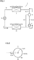
Fig. 1 is a diagram showing a refrigerant circuit of an air conditioner to which an oil separator according to each embodiment is applied. -
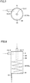
Fig. 2 is a top view of an oil separator according to the first embodiment. -
Fig. 3 is a side view of the oil separator in the first embodiment. -
Fig. 4 is a partial enlarged perspective cross-sectional view showing a liquid passage section in the first embodiment. -
Fig. 5 is a top view of the oil separator for illustrating the operation of the oil separator in the first embodiment. -
Fig. 6 is a side view of the oil separator for illustrating the operation of the oil separator in the first embodiment. -
Fig. 7 is a top view of an oil separator according to the second embodiment. -
Fig. 8 is a side view of the oil separator in the second embodiment. -
Fig. 9 is a partial enlarged perspective cross-sectional view showing a liquid passage section in the second embodiment. -
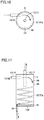
Fig. 10 is a top view of the oil separator for illustrating the operation of the oil separator in the second embodiment. -
Fig. 11 is a side view of the oil separator for illustrating the operation of the oil separator in the second embodiment. -
Fig. 12 is a cross-sectional view of an oil separator according to the first example in the third embodiment. -
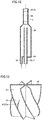
Fig. 13 is an enlarged perspective view showing an impeller section of the oil separator according to the first example in the third embodiment. -
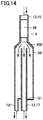
Fig. 14 is a cross-sectional view of the oil separator for illustrating the operation of the oil separator according to the first example in the third embodiment. -
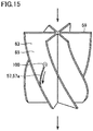
Fig. 15 is an enlarged perspective view showing an impeller section for illustrating the operation of the oil separator according to the first example in the third embodiment. -
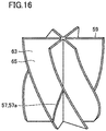
Fig. 16 is an enlarged perspective view showing an impeller section of an oil separator according to the second example in the third embodiment. -
Fig. 17 is an enlarged top view showing the impeller section of the oil separator according to the second example in the third embodiment. -
Fig. 18 is an enlarged perspective view showing the impeller section for illustrating the operation of the oil separator according to the second example in the third embodiment. -
Fig. 19 is a top view showing the impeller section for illustrating the operation of the oil separator according to the second example in the third embodiment. -
Fig. 20 is an enlarged perspective view showing an impeller section of an oil separator according to the third example in the third embodiment. -
Fig. 21 is the first partial enlarged cross-sectional view taken along a cross-sectional line XXI-XXI shown inFig. 20 in the third embodiment. -
Fig. 22 is the second partial enlarged cross-sectional view taken along cross-sectional line XXI-XXI shown inFig. 20 in the third embodiment. -
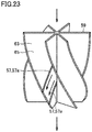
Fig. 23 is an enlarged perspective view showing the impeller section for illustrating the operation of the oil separator according to the third example in the third embodiment. -
Fig. 24 is the first partial enlarged cross-sectional view for illustrating the operation of the oil separator according to the third example in the third embodiment. -
Fig. 25 is the second partial enlarged cross-sectional view for illustrating the operation of the oil separator according to the third example in the third embodiment. -
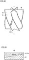
Fig. 26 is an enlarged perspective view showing an impeller section of an oil separator according to the fourth example in the third embodiment. -
Fig. 27 is a partial enlarged cross-sectional view taken along a cross-sectional line XXVII-XXVII shown inFig. 26 in the third embodiment. -
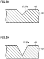
Fig. 28 is a partial enlarged cross-sectional view taken along a cross-sectional line XXVIII-XXVIII shown inFig. 26 in the third embodiment. -
Fig. 29 is a partial enlarged cross-sectional view taken along a cross-sectional line XXIX-XXIX shown inFig. 26 in the third embodiment. -
Fig. 30 is an enlarged perspective view showing the impeller section for illustrating the operation of the oil separator according to the fourth example in the third embodiment. -
Fig. 31 is a partial enlarged cross-sectional view corresponding toFig. 27 for illustrating the operation of the oil separator according to the fourth example in the third embodiment. -
Fig. 32 is a partial enlarged cross-sectional view corresponding toFig. 28 for illustrating the operation of the oil separator according to the fourth example in the third embodiment. -
Fig. 33 is a partial enlarged cross-sectional view corresponding toFig. 29 for illustrating the operation of the oil separator according to the fourth example in the third embodiment. -
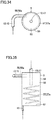
Fig. 34 is a top view of an oil separator according to the fourth embodiment. -
Fig. 35 is a side view of the oil separator in the fourth embodiment. -
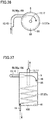
Fig. 36 is a top view of the oil separator for illustrating the operation of the oil separator in the fourth embodiment. -
Fig. 37 is a side view of the oil separator for illustrating the operation of the oil separator in the fourth embodiment. - First, an example of an air conditioner to which an oil separator is applied will be hereinafter described. As shown in
Fig. 1 , in anair conditioner 1, a refrigerant circuit is formed by sequentially connecting acompressor 3, anoil separator 5, acondenser 7, anexpansion valve 9, and anevaporator 11 through arefrigerant pipe 13. The refrigerant is compressed bycompressor 3 and turns into high-temperature and high-pressure gas refrigerant, which is then discharged fromcompressor 3. The discharged high-temperature and high-pressure gas refrigerant is conveyed throughoil separator 5 tocondenser 7. Incondenser 7, heat exchange is performed between the incoming refrigerant and the air supplied intocondenser 7. By heat exchange, the high-temperature and high-pressure gas refrigerant is condensed and turns into high-pressure liquid refrigerant. - By
expansion valve 9, the high-pressure liquid refrigerant supplied fromcondenser 7 is turned into refrigerant in a two-phase state including low-pressure gas refrigerant and liquid refrigerant. The refrigerant in a two-phase state flows intoevaporator 11. Inevaporator 11, heat exchange is performed between the incoming refrigerant in a two-phase state and the air supplied intoevaporator 11. By this heat exchange, the liquid refrigerant evaporates and turns into low-pressure gas refrigerant. - The low-pressure gas refrigerant supplied from
evaporator 11 flows intocompressor 3, in which the low-pressure gas refrigerant is compressed into high-temperature and high-pressure gas refrigerant. The high-temperature and high-pressure gas refrigerant is again discharged fromcompressor 3 and conveyed throughoil separator 5 tocondenser 7. This cycle is repeated thereafter. - In
air conditioner 1, the refrigeration oil contained in the refrigerant discharged fromcompressor 3 is separated from the refrigerant inoil separator 5. The separated refrigeration oil is to flow through anoil return pipe 19 so as to be returned to the suction side ofcompressor 3. - The following is an explanation about a specific structure of
oil separator 5 used inair conditioner 1 in each embodiment. -
Oil separator 5 according to the first embodiment will be hereinafter described. As shown inFigs. 2 and3 ,oil separator 5 includes aseparation container 56 that forms aseparation chamber 55. In consideration of productivity,separation container 56 is formed in an approximately circular cylindrical shape.Separation container 56 has a side surface portion to which an inlet pipe 15 is attached as a part ofrefrigerant pipe 13. Inlet pipe 15 is attached so as to extend in the direction approximately orthogonal to the tangential direction of the side surface portion ofseparation container 56. Inlet pipe 15 connects the discharge side ofcompressor 3 and oil separator 5 (separation container 56). -
Separation container 56 has an upper surface portion to which an outlet pipe 17 is attached as a part ofrefrigerant pipe 13. Outlet pipe 17 connects oil separator 5 (separation container 56) andcondenser 7. In a lower portion ofseparation container 56, anoil reservoir 61 is provided.Separation container 56 has a lower surface portion to whichoil return pipe 19 is attached.Oil return pipe 19 connectsoil reservoir 61 and the suction side ofcompressor 3. - As shown in
Fig. 4 ,separation container 56 has an inner wall surface provided with aliquid passage section 57 serving as a flow passage of refrigeration oil.Liquid passage section 57 is disposed to include a region facing the outlet port of inlet pipe 15.Liquid passage section 57 is provided with agroove 57a. In this case,groove 57a is disposed to extend in the direction of gravity towardoil reservoir 61. As shown in a lower partial view inFig. 4 ,groove 57a is formed to have a depth D that is gradually increased from an upper portion ofgroove 57a toward a lower portion thereof. In other words,groove 57a is formed to be gradually increased in depth from the upstream side of the flow of the refrigeration oil toward the downstream side thereof. - The following is an explanation about the operation by the above-mentioned
oil separator 5 for separating the refrigeration oil contained in the refrigerant. As shown inFigs. 5 and 6 , by the operation ofair conditioner 1, the high-temperature and high-pressure refrigerant discharged fromcompressor 3 flows through inlet pipe 15 intooil separator 5. The refrigerant contains refrigeration oil ofcompressor 3. The refrigerant containing refrigeration oil is discharged through inlet pipe 15 intoseparation container 56. Then, the refrigeration oil contained in the refrigerant is received ingroove 57a ofliquid passage section 57, thereby separating the refrigerant from the refrigeration oil. The refrigerant separated from the refrigeration oil flows through outlet pipe 17 so as to be fed into condenser 7 (seeFig. 1 ) as indicated by an arrow. - On the other hand, the refrigeration oil received in
groove 57a flows by gravity throughgroove 57a so as to be fed intooil reservoir 61 as indicated by an arrow.Refrigeration oil 100 accumulated inoil reservoir 61 flows intooil return pipe 19. As shown inFig. 1 , the refrigeration oil having flowed throughoil return pipe 19 is fed into the suction side ofcompressor 3. In this way, the refrigeration oil discharged together with the refrigerant is returned tocompressor 3. This operation is to be repeated thereafter whileair conditioner 1 is operating. - In
oil separator 5 ofair conditioner 1 as described above,groove 57a formed inliquid passage section 57 and receiving the refrigeration oil contained in the refrigerant is disposed to extend towardoil reservoir 61 in the direction of gravity. Also,groove 57a is formed to be gradually increased in depth from its upper portion toward its lower portion. - Thus, the area of contact between the refrigeration oil and
groove 57a is to increase from the upper portion ofgroove 57a toward the lower portion thereof. This means that the interfacial energy represented by the product of the area of contact and the surface tension gradually becomes larger in the negative direction from the upper portion ofgroove 57a toward the lower portion thereof. In other words, it means that the interfacial energy decreases. - Thus, by the action of gravity, the refrigeration oil flows actively through
groove 57a toward the lower portion ofgroove 57a at which the interfacial energy is smaller, so that the refrigeration oil is introduced intooil reservoir 61. When the refrigeration oil actively flows throughgroove 57a, accumulation of the refrigeration oil ingroove 57a can be suppressed while re-dispersion of the refrigeration oil by the refrigerant discharged from inlet pipe 15 can be prevented. As a result, the efficiency in separating the refrigeration oil contained in the refrigerant can be enhanced while the separated refrigeration oil can be returned to the compressor. - In order to reliably receive the refrigeration oil in
groove 57a, it is desirable that the position of the outlet port of inlet pipe 15 is located at the same height as the position at whichgroove 57a is started inliquid passage section 57. Furthermore,liquid passage section 57 may be formed in a range at least in the circumference portion of the length corresponding to the radius of inlet pipe 15 on the side wall surface ofseparation container 56 that faces the outlet port of inlet pipe 15. In order to reliably suppress re-dispersion of the refrigeration oil,liquid passage section 57 may be formed over the entire circumference of the inner wall surface ofseparation container 56. - Furthermore, in order to efficiently guide the refrigeration oil received in
groove 57a tooil reservoir 61,groove 57a formed inliquid passage section 57 is desirably formed to extend in the direction of gravity, but may be inclined slightly from the direction of gravity to such an extent that the refrigeration oil is not dispersed again by spraying of the refrigerant. Furthermore, in order to efficiently feed the refrigeration oil intooil return pipe 19,oil return pipe 19 may be disposed directly belowliquid passage section 57. -
Oil separator 5 according to the second embodiment will be hereinafter described. As shown inFigs. 7 and 8 ,oil separator 5 includesseparation container 56 formed in an approximate circular cylindrical shape and formingseparation chamber 55.Separation container 56 has a side surface portion to which inlet pipe 15 is attached as a part ofrefrigerant pipe 13. Inlet pipe 15 is attached so as to extend approximately in the tangential direction of the side surface portion ofseparation container 56. - As shown in
Fig. 9 ,separation container 56 has an inner wall surface provided withliquid passage section 57.Liquid passage section 57 is provided withgroove 57a extending in a spiral shape towardoil reservoir 61 along the inner wall surface ofseparation container 56. Spiral-shapedgroove 57a is formed to have depth D that is gradually increased from the upper portion ofgroove 57a toward the lower portion thereof. In other words, spiral-shapedgroove 57a is formed to be gradually increased in depth from the upstream side of the flow of the refrigeration oil toward the downstream side thereof. - Since the configuration other than the above is similar to that of
separation container 56 shown inFigs. 2 ,3 and the like, the same components will be designated by the same reference characters, and the description thereof will not be repeated unless otherwise required. - Then, the operation by the above-mentioned
oil separator 5 for separating the refrigeration oil contained in the refrigerant will be described. As shown inFigs. 10 and 11 , by the operation ofair conditioner 1, the high-temperature and high-pressure refrigerant discharged fromcompressor 3 flows through inlet pipe 15 intooil separator 5. In this case, inlet pipe 15 is attached so as to extend approximately in the tangential direction of the side surface portion ofseparation container 56. Thereby, while the refrigerant containing refrigeration oil flows along the inner wall surface ofseparation container 56 under centrifugal force, the refrigeration oil contained in the refrigerant is received ingroove 57a ofliquid passage section 57, so that the refrigerant is separated from the refrigeration oil. The refrigerant separated from the refrigeration oil flows through outlet pipe 17 as indicated by an arrow so as to be fed into condenser 7 (seeFig. 1 ). - On the other hand, upon reception of the flow of the refrigerant and the like discharged from inlet pipe 15, as indicated by an arrow, the refrigeration oil received in
groove 57a flows towardoil reservoir 61 throughgroove 57a extending in a spiral shape.Refrigeration oil 100 accumulated inoil reservoir 61 flows intooil return pipe 19. As shown inFig. 1 , the refrigeration oil having flowed throughoil return pipe 19 is fed into the suction side ofcompressor 3. Thus, the refrigeration oil discharged together with the refrigerant is returned tocompressor 3. This operation is to be repeated thereafter whileair conditioner 1 is operating. - In
oil separator 5 ofair conditioner 1 as described above, inlet pipe 15 is attached so as to extend approximately in the tangential direction of the side surface portion ofseparation container 56. Furthermore,groove 57a is formed in a spiral shape so as to extend along the flow of the refrigerant and the like that are to flow along the inner wall surface ofseparation container 56. - Accordingly, centrifugal force acts on the refrigerant containing the refrigeration oil flowing along the inner wall surface of
separation container 56. Thus, particularly the refrigeration oil is more likely to be received ingroove 57a ofliquid passage section 57. Furthermore, the flow of the refrigerant and the like discharged from inlet pipe 15 acts on the flow of the refrigeration oil received ingroove 57a so as to facilitate the flow of the refrigeration oil. - Furthermore,
groove 57a is formed to be gradually increased in depth from its upper portion toward its lower portion. Thereby, similarly to the above description, the refrigeration oil is more likely to actively flow throughgroove 57a toward the lower portion ofgroove 57a at which the interfacial energy is smaller. - Thereby, the refrigeration oil received in
groove 57a does not remain in the upper portion ofgroove 57a and is also not re-dispersed by the refrigerant and the like fed from inlet pipe 15, but flows throughgroove 57a extending in a spiral shape towardlower oil reservoir 61. As a result, the efficiency in separating the refrigeration oil contained in the refrigerant can be enhanced while the separated refrigeration oil can be reliably returned tocompressor 3. -
Oil separator 5 according to the third embodiment will be hereinafter described. - The first example will be hereinafter described. As shown in
Fig. 12 ,oil separator 5 includesseparation container 56 that formsseparation chamber 55. Animpeller section 59 is provided aboveseparation container 56. Inlet pipe 15 is attached as a part ofrefrigerant pipe 13 toimpeller section 59.Oil reservoir 61 is provided in the lower portion ofseparation container 56.Oil return pipe 19 is attached tooil reservoir 61. - Then,
impeller section 59 will be described. As shown inFig. 13 ,impeller section 59 includes avane 63 that is rotated by the flow of refrigerant and the like.Vane 63 has avane wall surface 65 provided withliquid passage section 57.Liquid passage section 57 is provided withgroove 57a.Groove 57a is formed along the flow occurring on the vane so as to extend from the rotation center side ofvane 63 toward the outer circumferential end thereof. - The following is an explanation about the operation by the above-mentioned
oil separator 5 for separating the refrigeration oil contained in the refrigerant. As shown inFig. 14 , by the operation ofair conditioner 1, the high-temperature and high-pressure refrigerant discharged fromcompressor 3 flows through inlet pipe 15 intooil separator 5. In this case,vane 63 ofimpeller section 59 is rotated by the flow of the refrigerant indicated by an arrow, as shown inFig. 15 . - When the refrigerant flows through
impeller section 59,refrigeration oil 100 contained in the refrigerant collides withvane wall surface 65 ofvane 63. Then,refrigeration oil 100 is received ingroove 57a formed along the flow occurring onvane 63, so that the refrigerant is separated from the refrigeration oil. The refrigerant separated from the refrigeration oil flows through outlet pipe 17 so as to be fed into condenser 7 (seeFig. 1 ) as indicated by an arrow. - On the other hand,
refrigeration oil 100 received ingroove 57a flows throughgroove 57a by centrifugal force and gravity so as to reach the outer circumferential end ofvane 63. The refrigeration oil having reached the outer circumferential end ofvane 63 collides with the inner wall surface ofseparation container 56 by centrifugal force and then flows along the inner wall surface towardoil reservoir 61. -
Refrigeration oil 100 accumulated inoil reservoir 61 flows intooil return pipe 19. As shown inFig. 1 , the refrigeration oil having flowed throughoil return pipe 19 is fed into the suction side ofcompressor 3. In this way, the refrigeration oil discharged together with the refrigerant is returned tocompressor 3. This operation is to be repeated thereafter whileair conditioner 1 is operating. -
Oil separator 5 ofair conditioner 1 as described above includesimpeller section 59 that is provided withvane 63 rotated by the flow of refrigerant and the like.Vane 63 has vanewall surface 65 provided withgroove 57a along the flow occurring onvane 63. Thus, when the refrigerant and the like flow alongvane wall surface 65 ofvane 63, the refrigeration oil contained in the refrigerant is more likely to be received ingroove 57a. By centrifugal force and gravity, the refrigeration oil received ingroove 57a does not remain in a portion ofgroove 57a located on the rotation center side ofvane 63, but flows toward the outer circumferential end ofvane 63 and then collides with the inner wall surface ofseparation container 56 so as to be fed intooil reservoir 61. - This suppresses flowing of the refrigeration oil into outlet pipe 17 as a result of re-dispersion of the refrigeration oil by the refrigerant and the like fed through inlet pipe 15. Thus, the refrigeration oil can be reliably guided to
oil reservoir 61. As a result, the efficiency in separating the refrigeration oil contained in the refrigerant can be enhanced while the separated refrigeration oil can be reliably returned tocompressor 3. - Then, the second example will be described. As shown in
Figs. 16 and17 ,impeller section 59 includesvane 63 rotated by the flow of the refrigerant and the like.Vane 63 has vanewall surface 65 provided withliquid passage section 57.Liquid passage section 57 is provided withgroove 57a formed to extend from the rotation center ofvane 63 toward the outer circumferential end thereof. The configuration other than the above is the same as that ofimpeller section 59 according to the first example. - The following is an explanation about the operation by the above-mentioned
oil separator 5 for separating the refrigeration oil contained in the refrigerant. By the operation ofair conditioner 1, the high-temperature and high-pressure refrigerant discharged fromcompressor 3 flows through inlet pipe 15 into oil separator 5 (seeFig. 14 ). As shown inFig. 18 , insideoil separator 5,vane 63 ofimpeller section 59 is rotated by the flow of the refrigerant and the like as indicated by an arrow. - When the refrigerant flows through
impeller section 59, the refrigeration oil contained in the refrigerant collides withvane wall surface 65 ofvane 63. In the refrigeration oil that collides withvane 63, the centrifugal force acting on the refrigeration oil that collides with the rotation center and its surrounding area ofvane 63 is smaller than the centrifugal force acting on the refrigeration oil that collides with the outer circumferential portion ofvane 63. Thus, as shown inFig. 19 ,refrigeration oil 100 having collided with the rotation center and its surrounding area ofvane 63 tends to remain onvane wall surface 65. - In the above-mentioned
oil separator 5,groove 57a is formed onvane wall surface 65 so as to extend along the flow occurring onvane 63 from the rotation center ofvane 63 toward the outer circumferential portion thereof. Thus,refrigeration oil 100 receiving relatively small centrifugal force and having collided with the rotation center and its surrounding area of the vane is received ingroove 57a and flows throughgroove 57a toward the outer circumferential end ofvane 63 without remaining in the rotation center and its surrounding area ofvane wall surface 65. - The refrigeration oil having reached the outer circumferential end of
vane 63 collides with the inner wall surface ofseparation container 56 by centrifugal force and the like, and then, flows along the inner wall surface towardoil reservoir 61.Refrigeration oil 100 remaining inoil reservoir 61 flows throughoil return pipe 19 so as to be fed to the suction side ofcompressor 3. In this way, the refrigeration oil discharged together with the refrigerant is returned to compressor 3 (seeFig. 1 ). This operation is to be repeated thereafter whileair conditioner 1 is operating. - In
oil separator 5 ofair conditioner 1 as described above,vane wall surface 65 is provided withgroove 57a that is formed to extend along the flow occurring onvane 63 from the rotation center ofvane 63 toward the outer circumferential end thereof. Thus,refrigeration oil 100 receiving relatively small centrifugal force and having collided with the rotation center and its surrounding area ofvane 63 is received ingroove 57a. By centrifugal force and gravity, the received refrigeration oil does not remain in the rotation center and its surrounding area ofvane wall surface 65, but flows toward the outer circumferential end ofvane 63, and then collides with the inner wall surface ofseparation container 56 so as to be fed intooil reservoir 61. - This suppresses flowing of the refrigeration oil into outlet pipe 17 as a result of re-dispersion of the refrigeration oil by the refrigerant and the like fed through inlet pipe 15. Thus, the refrigeration oil can be reliably guided to
oil reservoir 61. As a result, the efficiency in separating the refrigeration oil contained in the refrigerant can be enhanced while the separated refrigeration oil can be reliably returned tocompressor 3. - Then, the third example will be described. As shown in
Fig. 20 ,impeller section 59 includesvane 63 that is rotated by the flow of the refrigerant and the like.Vane 63 has vanewall surface 65 provided withliquid passage section 57.Liquid passage section 57 is provided with a plurality ofgrooves 57a formed to extend from the rotation center ofvane 63 toward the outer circumferential end thereof. - For example, one
groove 57a is separated at a distance L from anothergroove 57a.Groove 57a may have a rectangular cross-sectional shape having a width W and a depth D, for example, as shown inFig. 21 , or may have a V-shaped cross-sectional shape, for example, as shown inFig. 22 . The configuration other than the above is the same as that ofimpeller section 59 according to the second example. It should be noted that the cross-sectional shape ofgroove 57a is applicable also tooil separator 5 according to another embodiment. - The operation by the above-mentioned
oil separator 5 for separating the refrigeration oil contained in the refrigerant is substantially the same as that in the case ofoil separator 5 according to the second example. As shown inFig. 23 , insideoil separator 5,vane 63 ofimpeller section 59 is rotated by the flow of the refrigerant and the like as indicated by an arrow. Thus,refrigeration oil 100 receiving relatively small centrifugal force and having collided with the rotation center and its surrounding area of the vane is received ingroove 57a. As shown inFigs. 24 and 25 , the receivedrefrigeration oil 100 does not remain in the portion on the rotation center side ofvane wall surface 65, but flows throughgroove 57a toward the outer circumferential end ofvane 63. - By centrifugal force and the like, the refrigeration oil having reached the outer circumferential end of
vane 63 collides with the inner wall surface ofseparation container 56. Then, the refrigeration oil flows intooil reservoir 61 and then flows throughoil return pipe 19 so as to be fed to the suction side ofcompressor 3. In this way, the refrigeration oil discharged together with the refrigerant is returned to compressor 3 (seeFig. 1 ). This operation is to be repeated thereafter whileair conditioner 1 is operating. - In
oil separator 5 ofair conditioner 1 as described above,vane wall surface 65 is provided withgroove 57a formed to extend along the flow occurring onvane 63 from the rotation center ofvane 63 toward the outer circumferential end thereof. Thus,refrigeration oil 100 receiving relatively small centrifugal force and having collided with the rotation center and its surrounding area ofvane 63 is received ingroove 57a. - Also, a plurality of
such grooves 57a are formed. Thereby, onvane wall surface 65, the area of the refrigeration oil that is exposed to the refrigerant fed from inlet pipe 15 can be reduced. By centrifugal force and gravity, the received refrigeration oil does not remain in the portion on the rotation center side ofvane wall surface 65, but flows toward the outer circumferential end ofvane 63, and then, collides with the inner wall surface ofseparation container 56 so as to be fed intooil reservoir 61. - This suppresses flowing of the refrigeration oil into outlet pipe 17 as a result of re-dispersion of the refrigeration oil by the refrigerant and the like fed through inlet pipe 15. Thus, the refrigeration oil can be reliably guided to
oil reservoir 61. As a result, the efficiency in separating the refrigeration oil contained in the refrigerant can be enhanced while the separated refrigeration oil can be reliably returned tocompressor 3. - Then, the fourth example will be described. As shown in
Fig. 26 ,impeller section 59 includesvane 63 that is rotated by the flow of refrigerant and the like. -
Vane 63 has vanewall surface 65 provided withliquid passage section 57.Liquid passage section 57 is provided withgroove 57a formed to extend from the rotation center ofvane 63 toward the outer circumferential end thereof. As shown inFigs. 27 ,28 and 29 ,groove 57a is formed to be gradually increased in depth from the rotation center portion toward the outer circumferential end. The configuration other than the above is the same as that ofimpeller section 59 according to the second example. - The operation by the above-mentioned
oil separator 5 for separating the refrigeration oil contained in the refrigerant is substantially the same as that in the case ofoil separator 5 according to the second example. As shown inFig. 30 , insideoil separator 5,vane 63 ofimpeller section 59 is rotated by the flow of the refrigerant and the like as indicated by an arrow. Thus, the refrigeration oil receiving relatively small centrifugal force and having collided with the rotation center and its surrounding area of the vane is received ingroove 57a. As shown inFigs. 31 ,32 and 33 , the received refrigeration oil does not remain in the portion on the rotation center side ofvane wall surface 65, but flows throughgroove 57a toward the outer circumferential end ofvane 63. - By centrifugal force and the like, the refrigeration oil having reached the outer circumferential end of
vane 63 collides with the inner wall surface ofseparation container 56, and flows intooil reservoir 61, and then, flows throughoil return pipe 19 so as to be fed to the suction side ofcompressor 3. In this way, the refrigeration oil discharged together with the refrigerant is returned to compressor 3 (seeFig. 1 ). This operation is to be repeated thereafter whileair conditioner 1 is operating. - In
oil separator 5 ofair conditioner 1 as described above,vane wall surface 65 is provided withgroove 57a formed to extend along the flow occurring onvane 63 from the rotation center ofvane 63 toward the outer circumferential end thereof. Thus,refrigeration oil 100 receiving relatively small centrifugal force and having collided with the rotation center and its surrounding area ofvane 63 is received ingroove 57a. - Also,
groove 57a is formed so as to be gradually increased in depth from the rotation center toward the outer circumferential end. Thus, the refrigeration oil is more likely to actively flow throughgroove 57a towardgroove 57a on the outer circumferential end ofvane 63 at which the interfacial energy is smaller. Furthermore, by centrifugal force and gravity, the refrigeration oil does not remain in the portion on the rotation center side ofvane wall surface 65, but flows toward the outer circumferential end ofvane 63, and then, collides with the inner wall surface ofseparation container 56 so as to be fed intooil reservoir 61. - This suppresses flowing of the refrigeration oil into outlet pipe 17 as a result of re-dispersion of the refrigeration oil by the refrigerant and the like fed through inlet pipe 15. Thus, the refrigeration oil can be reliably guided to
oil reservoir 61. As a result, the efficiency in separating the refrigeration oil contained in the refrigerant can be enhanced while the separated refrigeration oil can be reliably returned tocompressor 3. - Then,
oil separator 5 according to the fourth embodiment will be described. As shown inFigs. 34 and 35 ,oil separator 5 includesseparation container 56 that has an approximately circular cylindrical shape and thatforms separation chamber 55.Separation container 56 has a side surface portion to which inlet pipe 15 is attached as a part ofrefrigerant pipe 13. Inlet pipe 15 is attached so as to extend approximately in the tangential direction of the side surface portion ofseparation container 56. - As inlet pipe 15, an L-shaped pipe bent in an L shape is used, for example. A liquid passage section 58 is provided in a portion of the inner wall surface of inlet pipe 15 that is located on the outer circumference side. Liquid passage section 58 is provided with a groove 58a formed to extend in the direction in which inlet pipe 15 extends. Since the configuration other than the above is similar to that of
oil separator 5 shown inFigs. 7, 8 , and9 , the same components will be designated by the same reference characters, and the description thereof will not be repeated unless otherwise required. - The following is an explanation about the operation by the above-mentioned
oil separator 5 for separating the refrigeration oil contained in the refrigerant. As shown inFigs. 36 and 37 , by the operation ofair conditioner 1, the high-temperature and high-pressure refrigerant discharged fromcompressor 3 flows through inlet pipe 15 intooil separator 5. In this case, inlet pipe 15 formed as a L-shaped pipe is provided with liquid passage section 58 that is located in a portion of the inner wall surface of inlet pipe 15 on the outer circumference side. Liquid passage section 58 is provided with groove 58a so as to extend in the direction in which inlet pipe 15 extends. Thereby, by centrifugal force acting when the refrigerant flows through L-shaped inlet pipe 15, the refrigeration oil contained in the refrigerant is readily received in groove 58a and guided to the outlet port of inlet pipe 15. - Furthermore, inlet pipe 15 is attached to
separation container 56 such that the side of inlet pipe 15 provided with groove 58a extends approximately in the tangential direction of the side surface portion ofseparation container 56. Furthermore,separation container 56 has an inner wall surface provided withgroove 57a that extends in a spiral shape towardoil reservoir 61. Thus, the refrigeration oil discharged from inlet pipe 15 is readily received ingroove 57a ofliquid passage section 57. - Upon reception of the flow of the refrigerant and the like discharged from inlet pipe 15, the refrigeration oil received in
groove 57a flows throughgroove 57a extending in a spiral shape so as to be guided tooil reservoir 61.Refrigeration oil 100 remaining inoil reservoir 61 is fed throughoil return pipe 19 to the suction side ofcompressor 3. In this way, the refrigeration oil discharged together with the refrigerant is returned tocompressor 3. This operation is to be repeated thereafter whileair conditioner 1 is operating. - In
oil separator 5 ofair conditioner 1 as described above, by the centrifugal force acting when the refrigerant flows through L-shaped inlet pipe 15, the refrigeration oil contained in the refrigerant is readily received in groove 58a so as to be guided to the outlet port of inlet pipe 15. Thereby, the variations in amount of the refrigeration oil remaining inside inlet pipe 15 are suppressed, the thickness of the refrigeration oil formed on the inner wall surface of inlet pipe 15 is reduced, and the flow velocity of the refrigerant is decreased. As a result, re-dispersion of the refrigeration oil by the refrigerant flowing through inlet pipe 15 can be suppressed. - Furthermore, inlet pipe 15 is attached to
separation container 56 such that the side of inlet pipe 15 provided with groove 58a extends approximately in the tangential direction of the side surface portion ofseparation container 56. Thereby, the refrigeration oil received in groove 58a is readily received ingroove 57a ofliquid passage section 57 so as to be guided tooil reservoir 61. As a result, remaining of the refrigeration oil is suppressed both inside inlet pipe 15 and insideseparation container 5, so that re-dispersion of the refrigeration oil can be further more effectively suppressed. - In the above-mentioned
oil separator 5, L-shaped inlet pipe 15 is applied as inlet pipe 15. Inlet pipe 15 is not limited to an L-shaped inlet pipe 15, but for example may be a U-shaped pipe that is bent in a U-shape as required. - Also in the above,
oil separator 5 has been described with regard to the case where L-shaped inlet pipe 15 is applied tooil separator 5 described in the second embodiment. In addition, foroil separator 5, an L-shaped inlet pipe 15 or a U-shaped inlet pipe 15 may be applied tooil separator 5 described in the third embodiment (seeFigs. 12 and 13 ), for example. - In this case, the refrigeration oil received in groove 58a formed on the inner wall surface of inlet pipe 15 is discharged from the outlet port of inlet pipe 15, so that the refrigeration oil mainly collides with the outer circumferential portion of rotating
vane 63 so as to be received ingroove 57a. Thus, as compared with the case ofoil separator 5 described in the third embodiment, a relatively small amount of refrigeration oil collides with the portion on the rotation center side ofvane 63 so as to be received ingroove 57a. -
Refrigeration oil 100 received ingroove 57a as a result of collision with the outer circumferential portion ofvane 63 flows throughgroove 57a under action of relatively high centrifugal force. The refrigeration oil having flowed throughgroove 57a collides with the inner wall surface ofseparation container 56 so as to be fed intooil reservoir 61. Thereby, the refrigeration oil received ingroove 57a does not remain ingroove 57a, but flows throughgroove 57a. Thus, re-dispersion of the refrigeration oil by the refrigerant and the like fed from inlet pipe 15 can be effectively suppressed. - The oil separators described in the above embodiments can be variously combined with one another as required.
- The embodiments disclosed herein are illustrative and non-restrictive. The present invention is defined by the scope of the claims, rather than the scope of the description above, and is intended to include any modifications within the meaning and scope equivalent to the scope of the claims.
- The present invention is effectively utilized in an air conditioner including an oil separator.
- 1 air conditioner, 3 compressor, 5 oil separator, 7 condenser, 9 expansion valve, 11 evaporator, 13 refrigerant pipe, 15 inlet pipe, 17 outlet pipe, 19 oil return pipe, 55 separation chamber, 56 separation container, 57, 58 liquid passage section, 59 impeller section, 61 oil reservoir, 63 vane, 65 vane wall surface, 100 refrigeration oil.
Claims (13)
- An oil separator for separating refrigeration oil contained in refrigerant from the refrigerant, the oil separator comprising:a separation container forming a separation chamber;an inlet pipe of the refrigerant, the inlet pipe communicating with the separation container;an outlet pipe of the refrigerant, the outlet pipe communicating with the separation container;an oil reservoir provided in the separation container and configured to store the refrigeration oil;a liquid passage section provided with a groove, the liquid passage section being disposed inside the separation container and configured to guide the refrigeration oil contained in the refrigerant to the oil reservoir; andan oil return pipe attached to the separation container and communicating with the oil reservoir, whereinthe liquid passage section has the groove that is formed to be gradually increased in depth from an upper portion of the groove toward a lower portion of the groove.
- The oil separator according to claim 1, wherein
the liquid passage section is disposed on an inner wall surface of the separation container, and
the groove is disposed to extend in a direction of gravity toward the oil reservoir. - The oil separator according to claim 1, wherein
the liquid passage section is disposed on an inner wall surface of the separation container, and
the groove is disposed in a spiral shape along the inner wall surface toward the oil reservoir. - The oil separator according to claim 1, wherein
the inlet pipe has a bent portion, and
another liquid passage section having another groove is formed on an inner wall surface on an outer circumference side of the bent portion. - The oil separator according to claim 4, wherein the inlet pipe is one of an L-shaped pipe and a U-shaped pipe.
- The oil separator according to claim 1, wherein the groove has a cross section formed in one of a V-shape and a rectangular shape.
- An oil separator for separating refrigeration oil contained in refrigerant from the refrigerant, the oil separator comprising:a separation container forming a separation chamber;an inlet pipe of the refrigerant, the inlet pipe communicating with the separation container;an outlet pipe of the refrigerant, the outlet pipe communicating with the separation container;an impeller section provided inside the separation container and having a vane configured to rotate by a flow of the refrigerant that is supplied from the inlet pipe;a liquid passage section provided in the vane and provided with a groove through which the refrigeration oil contained in the refrigerant is guided;an oil reservoir provided in the separation container and configured to store the refrigeration oil; andan oil return pipe attached to the separation container and communicating with the oil reservoir, whereinthe groove is provided on a wall surface of the vane so as to extend from a rotation center side of the vane toward an outer circumferential end of the vane.
- The oil separator according to claim 7, wherein a plurality of the grooves are provided on the wall surface at a distance from each other.
- The oil separator according to claim 7, wherein the groove is formed to be gradually increased in depth from the rotation center side of the vane toward the outer circumferential end of the vane.
- The oil separator according to claim 7, wherein
the inlet pipe has a bent portion, and
another liquid passage section having another groove is formed on an inner wall surface on an outer circumference side of the bent portion. - The oil separator according to claim 10, wherein the inlet pipe is one of an L-shaped pipe and a U-shaped pipe.
- The oil separator according to claim 7, wherein the groove has a cross section formed in one of a V-shape and a rectangular shape.
- An air conditioner comprising the oil separator according to any one of claims 1 to 12, wherein
a compressor, the oil separator, a condenser, an expansion valve, and an evaporator are connected sequentially in series by a refrigerant pipe,
the refrigerant pipe has the inlet pipe and the outlet pipe,
the inlet pipe connects a discharge side of the compressor and the oil separator,
the outlet pipe connects the oil separator and the condenser, and
the oil return pipe connects the oil separator and a suction side of the compressor.
Applications Claiming Priority (1)
| Application Number | Priority Date | Filing Date | Title |
|---|---|---|---|
| PCT/JP2017/035219 WO2019064427A1 (en) | 2017-09-28 | 2017-09-28 | Oil separator and air conditioner with same |
Publications (3)
| Publication Number | Publication Date |
|---|---|
| EP3690361A1 true EP3690361A1 (en) | 2020-08-05 |
| EP3690361A4 EP3690361A4 (en) | 2020-11-25 |
| EP3690361B1 EP3690361B1 (en) | 2021-12-22 |
Family
ID=65901067
Family Applications (1)
| Application Number | Title | Priority Date | Filing Date |
|---|---|---|---|
| EP17926760.4A Active EP3690361B1 (en) | 2017-09-28 | 2017-09-28 | Oil separator and air conditioner with same |
Country Status (6)
| Country | Link |
|---|---|
| US (1) | US11255587B2 (en) |
| EP (1) | EP3690361B1 (en) |
| JP (1) | JP6827554B2 (en) |
| CN (1) | CN111108333B (en) |
| ES (1) | ES2904309T3 (en) |
| WO (1) | WO2019064427A1 (en) |
Cited By (1)
| Publication number | Priority date | Publication date | Assignee | Title |
|---|---|---|---|---|
| KR20250174219A (en) | 2024-06-05 | 2025-12-12 | 엘지전자 주식회사 | Heat exchanging system |
Families Citing this family (3)
| Publication number | Priority date | Publication date | Assignee | Title |
|---|---|---|---|---|
| EP4151928A4 (en) * | 2020-05-11 | 2023-06-14 | Mitsubishi Electric Corporation | ACCUMULATOR AND REFRIGERATION DEVICE |
| CN116678143A (en) * | 2023-06-12 | 2023-09-01 | 山东凯新制冷工程有限公司 | A separator in a refrigeration system and its refrigeration system |
| CN117073276A (en) * | 2023-08-24 | 2023-11-17 | 珠海格力电器股份有限公司 | Oil separator and air conditioning unit |
Family Cites Families (22)
| Publication number | Priority date | Publication date | Assignee | Title |
|---|---|---|---|---|
| JPS53132148U (en) * | 1977-03-28 | 1978-10-19 | ||
| JPS5733345Y2 (en) * | 1977-11-15 | 1982-07-22 | ||
| US4255174A (en) * | 1978-11-28 | 1981-03-10 | Rolls-Royce Limited | Separator |
| JPS5869317A (en) * | 1981-10-22 | 1983-04-25 | Yoshikane Ikutake | Mist separator for smoke stack |
| JP2830618B2 (en) * | 1992-02-21 | 1998-12-02 | ダイキン工業株式会社 | Centrifugal oil separator |
| FR2738758B1 (en) * | 1995-09-15 | 1998-03-13 | Gec Alsthom Stein Ind | CENTRIFUGAL SEPARATOR IN PARTICULAR FOR A CIRCULATING FLUIDIZED BED BOILER |
| JP4356214B2 (en) * | 2000-08-21 | 2009-11-04 | 三菱電機株式会社 | Oil separator and outdoor unit |
| US6497114B1 (en) * | 2001-09-18 | 2002-12-24 | Visteon Global Technologies, Inc. | Oil separator |
| NL1026268C2 (en) * | 2004-05-26 | 2005-11-30 | Flash Technologies N V | In-line cyclone separator. |
| CN1782629A (en) * | 2004-11-29 | 2006-06-07 | 乐金电子(天津)电器有限公司 | Oil separator |
| KR100619785B1 (en) * | 2005-05-16 | 2006-09-06 | 엘지전자 주식회사 | Oil separator |
| CN101310154B (en) * | 2005-11-14 | 2012-12-05 | 日冷工业株式会社 | Gas-liquid separator and refrigerating apparatus equipped therewith |
| JP5395358B2 (en) | 2008-01-23 | 2014-01-22 | 日冷工業株式会社 | A gas-liquid separator and a refrigeration apparatus including the gas-liquid separator. |
| JP2014098500A (en) * | 2012-11-13 | 2014-05-29 | Samsung R&D Institute Japan Co Ltd | Shunt |
| JP2014145497A (en) * | 2013-01-28 | 2014-08-14 | Daikin Ind Ltd | Oil separator |
| WO2015140949A1 (en) * | 2014-03-19 | 2015-09-24 | 三菱電機株式会社 | Hermetic compressor and vapor compression refrigeration cycle device with said hermetic compressor |
| CN204063718U (en) * | 2014-09-26 | 2014-12-31 | 青岛开拓隆海制冷配件有限公司 | A kind of helical oil separator |
| CN204227780U (en) * | 2014-10-08 | 2015-03-25 | 新昌县宏宇制冷有限公司 | A kind of centrifugal oil separator |
| CN107076487B (en) * | 2014-10-23 | 2021-03-19 | 三菱电机株式会社 | oil separator |
| JP6594707B2 (en) * | 2015-08-27 | 2019-10-23 | 三菱重工サーマルシステムズ株式会社 | Two-stage compression refrigeration system |
| CN205279549U (en) | 2015-10-15 | 2016-06-01 | 珠海格力电器股份有限公司 | Vertical oil separator's inner tube, casing and vertical oil separator |
| CN206503217U (en) | 2016-12-07 | 2017-09-19 | 宿迁华夏建设(集团)工程有限公司 | It is a kind of to be used for the protection against erosion slope drainage device of hundred meter level side slopes |
-
2017
- 2017-09-28 ES ES17926760T patent/ES2904309T3/en active Active
- 2017-09-28 EP EP17926760.4A patent/EP3690361B1/en active Active
- 2017-09-28 WO PCT/JP2017/035219 patent/WO2019064427A1/en not_active Ceased
- 2017-09-28 US US16/651,073 patent/US11255587B2/en not_active Expired - Fee Related
- 2017-09-28 CN CN201780095044.9A patent/CN111108333B/en not_active Expired - Fee Related
- 2017-09-28 JP JP2019545489A patent/JP6827554B2/en not_active Expired - Fee Related
Cited By (1)
| Publication number | Priority date | Publication date | Assignee | Title |
|---|---|---|---|---|
| KR20250174219A (en) | 2024-06-05 | 2025-12-12 | 엘지전자 주식회사 | Heat exchanging system |
Also Published As
| Publication number | Publication date |
|---|---|
| WO2019064427A1 (en) | 2019-04-04 |
| EP3690361B1 (en) | 2021-12-22 |
| JPWO2019064427A1 (en) | 2020-10-22 |
| CN111108333A (en) | 2020-05-05 |
| ES2904309T3 (en) | 2022-04-04 |
| JP6827554B2 (en) | 2021-02-10 |
| US20200248941A1 (en) | 2020-08-06 |
| US11255587B2 (en) | 2022-02-22 |
| EP3690361A4 (en) | 2020-11-25 |
| CN111108333B (en) | 2021-11-30 |
Similar Documents
| Publication | Publication Date | Title |
|---|---|---|
| JP5395358B2 (en) | A gas-liquid separator and a refrigeration apparatus including the gas-liquid separator. | |
| EP3690361B1 (en) | Oil separator and air conditioner with same | |
| US7131292B2 (en) | Gas-liquid separator | |
| EP3144608B1 (en) | Oil separation device | |
| CN107655242B (en) | Gas-liquid separator of compression type refrigerator | |
| EP1568955B1 (en) | Oil separator and cooling-cycle apparatus using the same | |
| US9803900B2 (en) | Screw compressor and chiller unit provided with same | |
| KR102266411B1 (en) | Cyclone for separation of gas-liquid mixture, and a refrigerant accumulator containing this cyclone | |
| US20170276415A1 (en) | Oil separator | |
| CN103851843B (en) | Gas-liquid separator, and possess the refrigerating plant and vapour-cycling device of gas-liquid separator | |
| CN104603555A (en) | Accumulator | |
| CN105849482A (en) | External separator | |
| JP5498715B2 (en) | Gas-liquid separator and refrigeration apparatus equipped with the gas-liquid separator | |
| JP5634549B2 (en) | A gas-liquid separator and a refrigeration apparatus including the gas-liquid separator. | |
| JP2018155485A (en) | Gas-liquid separator and refrigeration apparatus equipped with gas-liquid separator | |
| CN115362343B (en) | evaporator | |
| CN104583690B (en) | Oil separator and method of manufacturing oil separator | |
| EP2741029B1 (en) | Oil separator | |
| US9022230B2 (en) | Oil separation means and refrigeration device equipped with the same | |
| EP4083541A1 (en) | Gas-liquid separation device and refrigeration cycle device | |
| JP2002277109A (en) | Oil separator | |
| EP4151928A1 (en) | Accumulator and refrigeration cycle device | |
| EP4386281A1 (en) | Refrigerant storage container, and refrigeration cycle device provided with said refrigerant storage container | |
| CN115653903B (en) | Compressor front cover assembly and compressor | |
| JP2015081711A (en) | Oil separator |
Legal Events
| Date | Code | Title | Description |
|---|---|---|---|
| STAA | Information on the status of an ep patent application or granted ep patent |
Free format text: STATUS: THE INTERNATIONAL PUBLICATION HAS BEEN MADE |
|
| PUAI | Public reference made under article 153(3) epc to a published international application that has entered the european phase |
Free format text: ORIGINAL CODE: 0009012 |
|
| STAA | Information on the status of an ep patent application or granted ep patent |
Free format text: STATUS: REQUEST FOR EXAMINATION WAS MADE |
|
| 17P | Request for examination filed |
Effective date: 20200320 |
|
| AK | Designated contracting states |
Kind code of ref document: A1 Designated state(s): AL AT BE BG CH CY CZ DE DK EE ES FI FR GB GR HR HU IE IS IT LI LT LU LV MC MK MT NL NO PL PT RO RS SE SI SK SM TR |
|
| AX | Request for extension of the european patent |
Extension state: BA ME |
|
| A4 | Supplementary search report drawn up and despatched |
Effective date: 20201023 |
|
| RIC1 | Information provided on ipc code assigned before grant |
Ipc: F25B 43/02 20060101AFI20201019BHEP Ipc: F25B 31/00 20060101ALI20201019BHEP |
|
| DAV | Request for validation of the european patent (deleted) | ||
| DAX | Request for extension of the european patent (deleted) | ||
| GRAP | Despatch of communication of intention to grant a patent |
Free format text: ORIGINAL CODE: EPIDOSNIGR1 |
|
| STAA | Information on the status of an ep patent application or granted ep patent |
Free format text: STATUS: GRANT OF PATENT IS INTENDED |
|
| RIC1 | Information provided on ipc code assigned before grant |
Ipc: F25B 43/02 20060101AFI20210623BHEP Ipc: F25B 31/00 20060101ALI20210623BHEP |
|
| INTG | Intention to grant announced |
Effective date: 20210713 |
|
| GRAS | Grant fee paid |
Free format text: ORIGINAL CODE: EPIDOSNIGR3 |
|
| GRAA | (expected) grant |
Free format text: ORIGINAL CODE: 0009210 |
|
| STAA | Information on the status of an ep patent application or granted ep patent |
Free format text: STATUS: THE PATENT HAS BEEN GRANTED |
|
| AK | Designated contracting states |
Kind code of ref document: B1 Designated state(s): AL AT BE BG CH CY CZ DE DK EE ES FI FR GB GR HR HU IE IS IT LI LT LU LV MC MK MT NL NO PL PT RO RS SE SI SK SM TR |
|
| REG | Reference to a national code |
Ref country code: GB Ref legal event code: FG4D |
|
| REG | Reference to a national code |
Ref country code: CH Ref legal event code: EP |
|
| REG | Reference to a national code |
Ref country code: DE Ref legal event code: R096 Ref document number: 602017051431 Country of ref document: DE |
|
| REG | Reference to a national code |
Ref country code: AT Ref legal event code: REF Ref document number: 1457320 Country of ref document: AT Kind code of ref document: T Effective date: 20220115 |
|
| REG | Reference to a national code |
Ref country code: IE Ref legal event code: FG4D |
|
| REG | Reference to a national code |
Ref country code: SE Ref legal event code: TRGR |
|
| REG | Reference to a national code |
Ref country code: ES Ref legal event code: FG2A Ref document number: 2904309 Country of ref document: ES Kind code of ref document: T3 Effective date: 20220404 |
|
| REG | Reference to a national code |
Ref country code: LT Ref legal event code: MG9D |
|
| PG25 | Lapsed in a contracting state [announced via postgrant information from national office to epo] |
Ref country code: RS Free format text: LAPSE BECAUSE OF FAILURE TO SUBMIT A TRANSLATION OF THE DESCRIPTION OR TO PAY THE FEE WITHIN THE PRESCRIBED TIME-LIMIT Effective date: 20211222 Ref country code: LT Free format text: LAPSE BECAUSE OF FAILURE TO SUBMIT A TRANSLATION OF THE DESCRIPTION OR TO PAY THE FEE WITHIN THE PRESCRIBED TIME-LIMIT Effective date: 20211222 Ref country code: FI Free format text: LAPSE BECAUSE OF FAILURE TO SUBMIT A TRANSLATION OF THE DESCRIPTION OR TO PAY THE FEE WITHIN THE PRESCRIBED TIME-LIMIT Effective date: 20211222 Ref country code: BG Free format text: LAPSE BECAUSE OF FAILURE TO SUBMIT A TRANSLATION OF THE DESCRIPTION OR TO PAY THE FEE WITHIN THE PRESCRIBED TIME-LIMIT Effective date: 20220322 |
|
| REG | Reference to a national code |
Ref country code: NL Ref legal event code: MP Effective date: 20211222 |
|
| REG | Reference to a national code |
Ref country code: AT Ref legal event code: MK05 Ref document number: 1457320 Country of ref document: AT Kind code of ref document: T Effective date: 20211222 |
|
| PG25 | Lapsed in a contracting state [announced via postgrant information from national office to epo] |
Ref country code: NO Free format text: LAPSE BECAUSE OF FAILURE TO SUBMIT A TRANSLATION OF THE DESCRIPTION OR TO PAY THE FEE WITHIN THE PRESCRIBED TIME-LIMIT Effective date: 20220322 Ref country code: LV Free format text: LAPSE BECAUSE OF FAILURE TO SUBMIT A TRANSLATION OF THE DESCRIPTION OR TO PAY THE FEE WITHIN THE PRESCRIBED TIME-LIMIT Effective date: 20211222 Ref country code: HR Free format text: LAPSE BECAUSE OF FAILURE TO SUBMIT A TRANSLATION OF THE DESCRIPTION OR TO PAY THE FEE WITHIN THE PRESCRIBED TIME-LIMIT Effective date: 20211222 Ref country code: GR Free format text: LAPSE BECAUSE OF FAILURE TO SUBMIT A TRANSLATION OF THE DESCRIPTION OR TO PAY THE FEE WITHIN THE PRESCRIBED TIME-LIMIT Effective date: 20220323 |
|
| PG25 | Lapsed in a contracting state [announced via postgrant information from national office to epo] |
Ref country code: NL Free format text: LAPSE BECAUSE OF FAILURE TO SUBMIT A TRANSLATION OF THE DESCRIPTION OR TO PAY THE FEE WITHIN THE PRESCRIBED TIME-LIMIT Effective date: 20211222 |
|
| PG25 | Lapsed in a contracting state [announced via postgrant information from national office to epo] |
Ref country code: SM Free format text: LAPSE BECAUSE OF FAILURE TO SUBMIT A TRANSLATION OF THE DESCRIPTION OR TO PAY THE FEE WITHIN THE PRESCRIBED TIME-LIMIT Effective date: 20211222 Ref country code: SK Free format text: LAPSE BECAUSE OF FAILURE TO SUBMIT A TRANSLATION OF THE DESCRIPTION OR TO PAY THE FEE WITHIN THE PRESCRIBED TIME-LIMIT Effective date: 20211222 Ref country code: RO Free format text: LAPSE BECAUSE OF FAILURE TO SUBMIT A TRANSLATION OF THE DESCRIPTION OR TO PAY THE FEE WITHIN THE PRESCRIBED TIME-LIMIT Effective date: 20211222 Ref country code: PT Free format text: LAPSE BECAUSE OF FAILURE TO SUBMIT A TRANSLATION OF THE DESCRIPTION OR TO PAY THE FEE WITHIN THE PRESCRIBED TIME-LIMIT Effective date: 20220422 Ref country code: EE Free format text: LAPSE BECAUSE OF FAILURE TO SUBMIT A TRANSLATION OF THE DESCRIPTION OR TO PAY THE FEE WITHIN THE PRESCRIBED TIME-LIMIT Effective date: 20211222 Ref country code: CZ Free format text: LAPSE BECAUSE OF FAILURE TO SUBMIT A TRANSLATION OF THE DESCRIPTION OR TO PAY THE FEE WITHIN THE PRESCRIBED TIME-LIMIT Effective date: 20211222 |
|
| PG25 | Lapsed in a contracting state [announced via postgrant information from national office to epo] |
Ref country code: PL Free format text: LAPSE BECAUSE OF FAILURE TO SUBMIT A TRANSLATION OF THE DESCRIPTION OR TO PAY THE FEE WITHIN THE PRESCRIBED TIME-LIMIT Effective date: 20211222 Ref country code: AT Free format text: LAPSE BECAUSE OF FAILURE TO SUBMIT A TRANSLATION OF THE DESCRIPTION OR TO PAY THE FEE WITHIN THE PRESCRIBED TIME-LIMIT Effective date: 20211222 |
|
| REG | Reference to a national code |
Ref country code: DE Ref legal event code: R097 Ref document number: 602017051431 Country of ref document: DE |
|
| PG25 | Lapsed in a contracting state [announced via postgrant information from national office to epo] |
Ref country code: IS Free format text: LAPSE BECAUSE OF FAILURE TO SUBMIT A TRANSLATION OF THE DESCRIPTION OR TO PAY THE FEE WITHIN THE PRESCRIBED TIME-LIMIT Effective date: 20220422 |
|
| PLBE | No opposition filed within time limit |
Free format text: ORIGINAL CODE: 0009261 |
|
| STAA | Information on the status of an ep patent application or granted ep patent |
Free format text: STATUS: NO OPPOSITION FILED WITHIN TIME LIMIT |
|
| PG25 | Lapsed in a contracting state [announced via postgrant information from national office to epo] |
Ref country code: DK Free format text: LAPSE BECAUSE OF FAILURE TO SUBMIT A TRANSLATION OF THE DESCRIPTION OR TO PAY THE FEE WITHIN THE PRESCRIBED TIME-LIMIT Effective date: 20211222 Ref country code: AL Free format text: LAPSE BECAUSE OF FAILURE TO SUBMIT A TRANSLATION OF THE DESCRIPTION OR TO PAY THE FEE WITHIN THE PRESCRIBED TIME-LIMIT Effective date: 20211222 |
|
| 26N | No opposition filed |
Effective date: 20220923 |
|
| PG25 | Lapsed in a contracting state [announced via postgrant information from national office to epo] |
Ref country code: SI Free format text: LAPSE BECAUSE OF FAILURE TO SUBMIT A TRANSLATION OF THE DESCRIPTION OR TO PAY THE FEE WITHIN THE PRESCRIBED TIME-LIMIT Effective date: 20211222 |
|
| PG25 | Lapsed in a contracting state [announced via postgrant information from national office to epo] |
Ref country code: MC Free format text: LAPSE BECAUSE OF FAILURE TO SUBMIT A TRANSLATION OF THE DESCRIPTION OR TO PAY THE FEE WITHIN THE PRESCRIBED TIME-LIMIT Effective date: 20211222 |
|
| REG | Reference to a national code |
Ref country code: CH Ref legal event code: PL |
|
| REG | Reference to a national code |
Ref country code: BE Ref legal event code: MM Effective date: 20220930 |
|
| P01 | Opt-out of the competence of the unified patent court (upc) registered |
Effective date: 20230512 |
|
| PG25 | Lapsed in a contracting state [announced via postgrant information from national office to epo] |
Ref country code: LU Free format text: LAPSE BECAUSE OF NON-PAYMENT OF DUE FEES Effective date: 20220928 |
|
| PG25 | Lapsed in a contracting state [announced via postgrant information from national office to epo] |
Ref country code: LI Free format text: LAPSE BECAUSE OF NON-PAYMENT OF DUE FEES Effective date: 20220930 Ref country code: IE Free format text: LAPSE BECAUSE OF NON-PAYMENT OF DUE FEES Effective date: 20220928 Ref country code: CH Free format text: LAPSE BECAUSE OF NON-PAYMENT OF DUE FEES Effective date: 20220930 |
|
| PG25 | Lapsed in a contracting state [announced via postgrant information from national office to epo] |
Ref country code: BE Free format text: LAPSE BECAUSE OF NON-PAYMENT OF DUE FEES Effective date: 20220930 |
|
| PGFP | Annual fee paid to national office [announced via postgrant information from national office to epo] |
Ref country code: TR Payment date: 20230926 Year of fee payment: 7 Ref country code: IT Payment date: 20230810 Year of fee payment: 7 Ref country code: GB Payment date: 20230810 Year of fee payment: 7 |
|
| PGFP | Annual fee paid to national office [announced via postgrant information from national office to epo] |
Ref country code: SE Payment date: 20230810 Year of fee payment: 7 Ref country code: FR Payment date: 20230808 Year of fee payment: 7 Ref country code: DE Payment date: 20230802 Year of fee payment: 7 |
|
| PGFP | Annual fee paid to national office [announced via postgrant information from national office to epo] |
Ref country code: ES Payment date: 20231003 Year of fee payment: 7 |
|
| REG | Reference to a national code |
Ref country code: DE Ref legal event code: R084 Ref document number: 602017051431 Country of ref document: DE |
|
| PG25 | Lapsed in a contracting state [announced via postgrant information from national office to epo] |
Ref country code: CY Free format text: LAPSE BECAUSE OF FAILURE TO SUBMIT A TRANSLATION OF THE DESCRIPTION OR TO PAY THE FEE WITHIN THE PRESCRIBED TIME-LIMIT Effective date: 20211222 |
|
| REG | Reference to a national code |
Ref country code: ES Ref legal event code: GC2A Effective date: 20240513 |
|
| PG25 | Lapsed in a contracting state [announced via postgrant information from national office to epo] |
Ref country code: MK Free format text: LAPSE BECAUSE OF FAILURE TO SUBMIT A TRANSLATION OF THE DESCRIPTION OR TO PAY THE FEE WITHIN THE PRESCRIBED TIME-LIMIT Effective date: 20211222 Ref country code: HU Free format text: LAPSE BECAUSE OF FAILURE TO SUBMIT A TRANSLATION OF THE DESCRIPTION OR TO PAY THE FEE WITHIN THE PRESCRIBED TIME-LIMIT; INVALID AB INITIO Effective date: 20170928 |
|
| REG | Reference to a national code |
Ref country code: GB Ref legal event code: 746 Effective date: 20240605 |
|
| PG25 | Lapsed in a contracting state [announced via postgrant information from national office to epo] |
Ref country code: MT Free format text: LAPSE BECAUSE OF FAILURE TO SUBMIT A TRANSLATION OF THE DESCRIPTION OR TO PAY THE FEE WITHIN THE PRESCRIBED TIME-LIMIT Effective date: 20211222 |
|
| REG | Reference to a national code |
Ref country code: DE Ref legal event code: R119 Ref document number: 602017051431 Country of ref document: DE |
|
| REG | Reference to a national code |
Ref country code: SE Ref legal event code: EUG |
|
| GBPC | Gb: european patent ceased through non-payment of renewal fee |
Effective date: 20240928 |
|
| PG25 | Lapsed in a contracting state [announced via postgrant information from national office to epo] |
Ref country code: DE Free format text: LAPSE BECAUSE OF NON-PAYMENT OF DUE FEES Effective date: 20250401 |
|
| PG25 | Lapsed in a contracting state [announced via postgrant information from national office to epo] |
Ref country code: GB Free format text: LAPSE BECAUSE OF NON-PAYMENT OF DUE FEES Effective date: 20240928 |
|
| PG25 | Lapsed in a contracting state [announced via postgrant information from national office to epo] |
Ref country code: IT Free format text: LAPSE BECAUSE OF NON-PAYMENT OF DUE FEES Effective date: 20240928 |
|
| PG25 | Lapsed in a contracting state [announced via postgrant information from national office to epo] |
Ref country code: FR Free format text: LAPSE BECAUSE OF NON-PAYMENT OF DUE FEES Effective date: 20240930 |
|
| PG25 | Lapsed in a contracting state [announced via postgrant information from national office to epo] |
Ref country code: SE Free format text: LAPSE BECAUSE OF NON-PAYMENT OF DUE FEES Effective date: 20240929 |
|
| REG | Reference to a national code |
Ref country code: ES Ref legal event code: FD2A Effective date: 20251105 |
|
| PG25 | Lapsed in a contracting state [announced via postgrant information from national office to epo] |
Ref country code: ES Free format text: LAPSE BECAUSE OF NON-PAYMENT OF DUE FEES Effective date: 20240929 |