EP3689692B1 - Systèmes indicateurs de la santé de freins au moyen de l'énergie d'entrée et de sortie - Google Patents
Systèmes indicateurs de la santé de freins au moyen de l'énergie d'entrée et de sortie Download PDFInfo
- Publication number
- EP3689692B1 EP3689692B1 EP20165084.3A EP20165084A EP3689692B1 EP 3689692 B1 EP3689692 B1 EP 3689692B1 EP 20165084 A EP20165084 A EP 20165084A EP 3689692 B1 EP3689692 B1 EP 3689692B1
- Authority
- EP
- European Patent Office
- Prior art keywords
- brake
- health
- thermal energy
- brakes
- data
- Prior art date
- Legal status (The legal status is an assumption and is not a legal conclusion. Google has not performed a legal analysis and makes no representation as to the accuracy of the status listed.)
- Active
Links
- 230000036541 health Effects 0.000 title claims description 136
- 238000000034 method Methods 0.000 claims description 71
- 238000012544 monitoring process Methods 0.000 claims description 63
- 230000008569 process Effects 0.000 claims description 29
- 230000008859 change Effects 0.000 claims description 25
- 230000004044 response Effects 0.000 claims description 16
- 238000007689 inspection Methods 0.000 claims description 12
- 230000000694 effects Effects 0.000 claims description 8
- 238000004422 calculation algorithm Methods 0.000 description 28
- 238000005259 measurement Methods 0.000 description 13
- 230000007246 mechanism Effects 0.000 description 12
- 238000004891 communication Methods 0.000 description 10
- 238000012545 processing Methods 0.000 description 10
- 230000009977 dual effect Effects 0.000 description 9
- 230000006870 function Effects 0.000 description 9
- 238000012423 maintenance Methods 0.000 description 9
- 238000011835 investigation Methods 0.000 description 7
- 238000009529 body temperature measurement Methods 0.000 description 6
- 238000010586 diagram Methods 0.000 description 5
- 238000012549 training Methods 0.000 description 5
- 230000007613 environmental effect Effects 0.000 description 4
- 230000007774 longterm Effects 0.000 description 4
- 230000008439 repair process Effects 0.000 description 4
- 230000015556 catabolic process Effects 0.000 description 3
- 238000006731 degradation reaction Methods 0.000 description 3
- 230000001133 acceleration Effects 0.000 description 2
- 238000013459 approach Methods 0.000 description 2
- 230000008901 benefit Effects 0.000 description 2
- 230000005540 biological transmission Effects 0.000 description 2
- 238000009826 distribution Methods 0.000 description 2
- 238000011058 failure modes and effects analysis Methods 0.000 description 2
- 230000008376 long-term health Effects 0.000 description 2
- 238000007726 management method Methods 0.000 description 2
- 230000002159 abnormal effect Effects 0.000 description 1
- 230000009471 action Effects 0.000 description 1
- 230000002547 anomalous effect Effects 0.000 description 1
- 230000003190 augmentative effect Effects 0.000 description 1
- 238000004364 calculation method Methods 0.000 description 1
- 238000007796 conventional method Methods 0.000 description 1
- 230000008878 coupling Effects 0.000 description 1
- 238000010168 coupling process Methods 0.000 description 1
- 238000005859 coupling reaction Methods 0.000 description 1
- 125000004122 cyclic group Chemical group 0.000 description 1
- 238000013480 data collection Methods 0.000 description 1
- 230000007423 decrease Effects 0.000 description 1
- 238000001514 detection method Methods 0.000 description 1
- 238000011161 development Methods 0.000 description 1
- 230000005662 electromechanics Effects 0.000 description 1
- 230000010006 flight Effects 0.000 description 1
- 239000000446 fuel Substances 0.000 description 1
- 238000003384 imaging method Methods 0.000 description 1
- 238000012804 iterative process Methods 0.000 description 1
- 239000004973 liquid crystal related substance Substances 0.000 description 1
- 239000000463 material Substances 0.000 description 1
- 238000012986 modification Methods 0.000 description 1
- 230000004048 modification Effects 0.000 description 1
- 230000003864 performance function Effects 0.000 description 1
- 238000001556 precipitation Methods 0.000 description 1
- 238000007637 random forest analysis Methods 0.000 description 1
- 239000007787 solid Substances 0.000 description 1
- 230000003068 static effect Effects 0.000 description 1
Images


Classifications
-
- B—PERFORMING OPERATIONS; TRANSPORTING
- B60—VEHICLES IN GENERAL
- B60T—VEHICLE BRAKE CONTROL SYSTEMS OR PARTS THEREOF; BRAKE CONTROL SYSTEMS OR PARTS THEREOF, IN GENERAL; ARRANGEMENT OF BRAKING ELEMENTS ON VEHICLES IN GENERAL; PORTABLE DEVICES FOR PREVENTING UNWANTED MOVEMENT OF VEHICLES; VEHICLE MODIFICATIONS TO FACILITATE COOLING OF BRAKES
- B60T17/00—Component parts, details, or accessories of power brake systems not covered by groups B60T8/00, B60T13/00 or B60T15/00, or presenting other characteristic features
- B60T17/18—Safety devices; Monitoring
- B60T17/22—Devices for monitoring or checking brake systems; Signal devices
- B60T17/221—Procedure or apparatus for checking or keeping in a correct functioning condition of brake systems
-
- B—PERFORMING OPERATIONS; TRANSPORTING
- B60—VEHICLES IN GENERAL
- B60T—VEHICLE BRAKE CONTROL SYSTEMS OR PARTS THEREOF; BRAKE CONTROL SYSTEMS OR PARTS THEREOF, IN GENERAL; ARRANGEMENT OF BRAKING ELEMENTS ON VEHICLES IN GENERAL; PORTABLE DEVICES FOR PREVENTING UNWANTED MOVEMENT OF VEHICLES; VEHICLE MODIFICATIONS TO FACILITATE COOLING OF BRAKES
- B60T17/00—Component parts, details, or accessories of power brake systems not covered by groups B60T8/00, B60T13/00 or B60T15/00, or presenting other characteristic features
- B60T17/18—Safety devices; Monitoring
- B60T17/22—Devices for monitoring or checking brake systems; Signal devices
-
- B—PERFORMING OPERATIONS; TRANSPORTING
- B60—VEHICLES IN GENERAL
- B60T—VEHICLE BRAKE CONTROL SYSTEMS OR PARTS THEREOF; BRAKE CONTROL SYSTEMS OR PARTS THEREOF, IN GENERAL; ARRANGEMENT OF BRAKING ELEMENTS ON VEHICLES IN GENERAL; PORTABLE DEVICES FOR PREVENTING UNWANTED MOVEMENT OF VEHICLES; VEHICLE MODIFICATIONS TO FACILITATE COOLING OF BRAKES
- B60T8/00—Arrangements for adjusting wheel-braking force to meet varying vehicular or ground-surface conditions, e.g. limiting or varying distribution of braking force
- B60T8/17—Using electrical or electronic regulation means to control braking
- B60T8/1701—Braking or traction control means specially adapted for particular types of vehicles
- B60T8/1703—Braking or traction control means specially adapted for particular types of vehicles for aircrafts
-
- B—PERFORMING OPERATIONS; TRANSPORTING
- B64—AIRCRAFT; AVIATION; COSMONAUTICS
- B64F—GROUND OR AIRCRAFT-CARRIER-DECK INSTALLATIONS SPECIALLY ADAPTED FOR USE IN CONNECTION WITH AIRCRAFT; DESIGNING, MANUFACTURING, ASSEMBLING, CLEANING, MAINTAINING OR REPAIRING AIRCRAFT, NOT OTHERWISE PROVIDED FOR; HANDLING, TRANSPORTING, TESTING OR INSPECTING AIRCRAFT COMPONENTS, NOT OTHERWISE PROVIDED FOR
- B64F5/00—Designing, manufacturing, assembling, cleaning, maintaining or repairing aircraft, not otherwise provided for; Handling, transporting, testing or inspecting aircraft components, not otherwise provided for
- B64F5/60—Testing or inspecting aircraft components or systems
-
- F—MECHANICAL ENGINEERING; LIGHTING; HEATING; WEAPONS; BLASTING
- F16—ENGINEERING ELEMENTS AND UNITS; GENERAL MEASURES FOR PRODUCING AND MAINTAINING EFFECTIVE FUNCTIONING OF MACHINES OR INSTALLATIONS; THERMAL INSULATION IN GENERAL
- F16D—COUPLINGS FOR TRANSMITTING ROTATION; CLUTCHES; BRAKES
- F16D66/00—Arrangements for monitoring working conditions, e.g. wear, temperature
- F16D66/02—Apparatus for indicating wear
-
- B—PERFORMING OPERATIONS; TRANSPORTING
- B60—VEHICLES IN GENERAL
- B60T—VEHICLE BRAKE CONTROL SYSTEMS OR PARTS THEREOF; BRAKE CONTROL SYSTEMS OR PARTS THEREOF, IN GENERAL; ARRANGEMENT OF BRAKING ELEMENTS ON VEHICLES IN GENERAL; PORTABLE DEVICES FOR PREVENTING UNWANTED MOVEMENT OF VEHICLES; VEHICLE MODIFICATIONS TO FACILITATE COOLING OF BRAKES
- B60T2270/00—Further aspects of brake control systems not otherwise provided for
- B60T2270/40—Failsafe aspects of brake control systems
- B60T2270/413—Plausibility monitoring, cross check, redundancy
-
- B—PERFORMING OPERATIONS; TRANSPORTING
- B64—AIRCRAFT; AVIATION; COSMONAUTICS
- B64C—AEROPLANES; HELICOPTERS
- B64C25/00—Alighting gear
- B64C25/32—Alighting gear characterised by elements which contact the ground or similar surface
- B64C25/42—Arrangement or adaptation of brakes
-
- F—MECHANICAL ENGINEERING; LIGHTING; HEATING; WEAPONS; BLASTING
- F16—ENGINEERING ELEMENTS AND UNITS; GENERAL MEASURES FOR PRODUCING AND MAINTAINING EFFECTIVE FUNCTIONING OF MACHINES OR INSTALLATIONS; THERMAL INSULATION IN GENERAL
- F16D—COUPLINGS FOR TRANSMITTING ROTATION; CLUTCHES; BRAKES
- F16D66/00—Arrangements for monitoring working conditions, e.g. wear, temperature
- F16D2066/001—Temperature
-
- F—MECHANICAL ENGINEERING; LIGHTING; HEATING; WEAPONS; BLASTING
- F16—ENGINEERING ELEMENTS AND UNITS; GENERAL MEASURES FOR PRODUCING AND MAINTAINING EFFECTIVE FUNCTIONING OF MACHINES OR INSTALLATIONS; THERMAL INSULATION IN GENERAL
- F16D—COUPLINGS FOR TRANSMITTING ROTATION; CLUTCHES; BRAKES
- F16D66/00—Arrangements for monitoring working conditions, e.g. wear, temperature
- F16D2066/005—Force, torque, stress or strain
Definitions
- This invention generally relates to brake systems.
- this invention relates to systems and methods for monitoring the health of brakes.
- Vehicles particularly commercial air and land vehicles, typically include some type of performance monitoring system that records data regarding the vehicle performance, which includes the performance of the various components of the vehicle, such as a fault in one of the vehicle subsystems.
- the data includes a record of certain performance events that occur during the operation of the vehicle.
- the performance monitoring system typically conducts data collection and reports all of the data collected to the user. The user then may utilize the data in determining the type of maintenance, if any, that the vehicle may need. For example, if the data indicates that a particular component of the vehicle is anomalous, then the user can perform appropriate maintenance on the vehicle at the next opportunity.
- brakes in the form of stacked discs frequently comprise material that wears with use, which wear decreases the thickness of the brake discs and the height of the stack. Worn brake discs are replaced when wear exceeds a predetermined amount.
- LVDT linear variable differential transformer
- Document DE 202 08 841 U1 discloses a method of monitoring brake lining wear in motor vehicles that utilizes a recording of a generated break energy during breaking maneuver and comparing it with a theoretical amount of energy that would be generated by a new brake system.
- brake health wear/degradation/health
- a method for monitoring brake health is proposed herein in which the ratio of input energy to output energy during braking is calculated.
- the input energy is a function of commanded brake force and speed.
- the output energy may be estimated using any one of a plurality of methods.
- the methods proposed herein provide insight into the health of the braking system, allowing an airline operator to perform a cost-effective preventative maintenance, thereby improving the operational reliability of the aircraft.
- the output energy can be measured by measuring the increase in temperature over time during brake application. In accordance with other embodiments, the output energy can be measured by measuring the actual brake force over time during brake application. When using brake temperatures, it may be desirable to reduce variability due to operational and environmental factors that affect measured temperature.
- the temperatures in a pair of similar brakes are compared.
- the respective measured temperatures during dual brake application should be the same if both brakes are in the same operational state (e.g., if both are healthy). If the respective measured temperatures of the two similar brakes differ by an amount that exceeds a specified threshold, the system produces a flag that one of the two brakes may be a candidate for repair or replacement.
- the term "flag" should be construed broadly to encompass any of the following: an analog signal, a digital code, a report, a notice, an alert or a warning.
- variability due to operational and environmental factors is reduced by comparing the measured brake temperatures for one brake with selected brake temperature data collected from the same brake during other landings under similar conditions.
- brake health indicator values are calculated using recorded flight data augmented with other operational and environmental data. This takes advantage of how the relationship between input versus output energy signatures varies due to braking system degradations. Operational and environmental data are used to help normalize and increase the fidelity of the calculated energy signatures.
- a method for monitoring health of a brake on a vehicle comprising: (a) generating brake force command data representing brake force commands; (b) applying brake forces to the brake in response to the brake force commands; (c) generating groundspeed data representing measurements of groundspeed of the vehicle during application of brake forces; (d) generating brake data representing measurements of a condition of the brake during application of brake forces; (e) collecting the brake force command data, groundspeed data and brake data onboard the vehicle to form collected data; (f) transmitting the collected data to a computer system that is configured to perform steps (g), (h) and (i); (g) calculating a current value of a brake health indicator that is a ratio of a brake input energy to a brake output energy based on the collected data; (h) determining whether the current value of the brake health indicator is outside a range of expected values or not; and (i) generating a flag in response to a determination in step (h) that the current value of the brake health indicator is outside the range
- the expected values may be are derived from historical brake condition data acquired under similar landing conditions for the same brake or similar brakes.
- the foregoing method may further comprise the following steps: (j) performing an inspection of the brake following generation of the flag; (k) determining whether the brake should be repaired or replaced or not based on results of the inspection; and (I) repairing or replacing the brake following a determination that the brake should be repaired or replaced.
- the method further comprises calculating a brake input energy and measuring a brake output energy, wherein calculating the current value of the brake health indicator comprises calculating a ratio of the calculated brake input energy and the measured brake output energy.
- calculating the brake input energy comprises calculating a sum over time of a product of a measured groundspeed of the vehicle and a commanded brake force during application of brake forces.
- measuring the brake output energy comprises measuring a first brake temperature at a time before application of brake forces and measuring a second brake temperature at a time after application of brake forces. This method may further comprise removing the effect of other factors that also affect temperature.
- measuring the brake output energy comprises summing a product of a groundspeed of the vehicle and a brake force over time during application of brake forces.
- a method for monitoring health of brakes on a vehicle comprising: (a) generating brake force command data representing brake force commands; (b) applying brake forces to first and second brakes in response to the brake force commands; (c) generating first thermal energy data representing an amount of thermal energy produced by the first brake during application of brake forces; (d) generating second thermal energy data representing an amount of thermal energy produced by the second brake during application of brake forces; (e) collecting the first and second thermal energy data onboard the vehicle to form collected temperature data; (f) transmitting the collected first and second thermal energy data to a computer system that is configured to perform steps (g), (h) and (i); (g) calculating a current value of a brake health indicator that is a ratio of the amounts of thermal energy respectively produced by the first and second brakes during application of brake forces; (h) determining whether the current value of the brake health indicator is outside a range of expected values or not; and (i) generating a flag in response to a determination in step (h)
- the first thermal energy data comprises first brake temperature data representing a temperature change in the first brake during application of brake forces
- the second thermal energy data comprises second brake temperature data representing a temperature change in the second brake during application of brake forces
- calculating the current value of the brake health indicator comprises calculating a ratio of the temperature change in the first brake and the temperature change in the second brake.
- This method may further comprise removing the effect of other factors that also affect temperature.
- the expected values may be derived from historical brake condition data acquired under similar landing conditions for the same brake or similar brakes.
- a further aspect of the subject matter disclosed in detail below is a system for monitoring health of a brake on a vehicle, comprising a computer system configured to perform the following operations: receiving brake force command data, vehicle groundspeed data and brake condition measurement data; calculating a current value of a brake health indicator that is a ratio of a calculated brake input energy and a measured brake output energy based on the received data; determining whether the current value of the brake health indicator is outside a range of expected values or not; and generating a flag in response to a determination that the current value of the brake health indicator is outside the range of expected values.
- the computer system is further configured to calculate the brake input energy by calculating a sum over time of a product of measured groundspeed of the vehicle and commanded brake force during application of brake forces.
- the brake condition measurement data comprises a first brake temperature measured at a time before application of brake forces and a second brake temperature measured at a time after application of brake forces.
- the brake condition measurement data comprises brake force measured during application of brake forces
- measuring the brake output energy comprises summing a product of measured groundspeed of the vehicle and measured brake force over time during application of brake forces.
- Yet another aspect is a system for monitoring health of brakes on a vehicle, comprising a computer system configured to perform the following operations: receiving first thermal energy data representing an amount of thermal energy produced by a first brake during application of brake forces; receiving second thermal energy data representing an amount of thermal energy produced by a second brake during application of brake forces; calculating a current value of a brake health indicator that is a ratio of the amounts of thermal energy respectively produced by the first and second brakes during application of brake forces; determining whether the current value of the brake health indicator is outside a range of expected values or not; and generating a flag in response to a determination that the current value of the brake health indicator is outside the range of expected values.
- the first thermal energy data comprises first brake temperature data representing a temperature change in the first brake during application of brake forces
- the second thermal energy data comprises second brake temperature data representing a temperature change in the second brake during application of brake forces
- calculating the current value of the brake health indicator comprises calculating a ratio of the temperature change in the first brake and the temperature change in the second brake.
- the example aircraft described herein employs an electric brake system, which may be powered by any suitable power supply, such as an active aircraft power supply that is operational when the aircraft engine(s) are running or a main aircraft battery.
- the electric brake system in turn may comprise multiple electric braking subsystems, each electric braking subsystem being associated with respective main landing gears of an aircraft.
- each main landing gear has a respective wheel group comprising two fore wheels and two aft wheels arranged in a rectangular configuration.
- the left fore wheel and left aft wheel may be disposed either inboard or outboard with respect to the right fore wheel and right aft wheel.
- the terms “left” and “right” refer to the port and starboard of the aircraft, respectively.
- the left and right electric brake subsystems may be independently controlled in the manner described below.
- FIG. 1 is a schematic representation of an example embodiment of an electric brake system 102 for an aircraft.
- the aircraft may employ left and right electric brake subsystems which are similarly configured to have the architecture depicted in FIG. 1 .
- each of the left and right electric brake subsystems comprises the following components: a brake pedal 106; other brake actuation mechanisms 108; a brake system control unit (BSCU) 110 coupled to brake pedal 106 and to the other brake actuation mechanisms 108; an outboard electric brake actuator controller (EBAC) 112 coupled to BSCU 110; an inboard EBAC 114 coupled to BSCU 110; an outboard wheel group that includes a fore wheel 116 and an aft wheel 118 rotatably coupled to respective axles of an undercarriage bogie 104; an inboard wheel group that includes a fore wheel 120 and an aft wheel 122 rotatably coupled to respective axles of the undercarriage bogie 104; electric brake mechanisms 124, 126 operatively coupled to fore and a
- a digital data communication bus or buses may be configured to communicate EBAC control signals from BSCU 110 to the EBACs, to communicate brake mechanism control signals (e.g., actuator control signals) from the EBACs to the electric brake actuators, etc.
- BSCU 110 reacts to manipulation of brake pedal 106 and generates control signals that are received by EBACs 112, 114.
- EBACs 112, 114 generate brake mechanism control signals that are received by electric brake mechanisms 124, 126, 128, 130.
- the wheel brakes engage to impede or prevent rotation of the respective wheels.
- BSCU 110 is an electronic control unit that has embedded software that digitally computes EBAC control signals that represent braking commands.
- BSCU 110 monitors various aircraft inputs to provide control functions. For example, BSCU 110 obtains pilot command control signals from brake pedal 106, along with additional command control signals from other brake actuation mechanisms 108.
- BSCU 110 may also receive wheel data (e.g., wheel speed, rotational direction, tire pressure, etc.) from remote data concentrators 132, 134, 136, 138.
- wheel data e.g., wheel speed, rotational direction, tire pressure, etc.
- BSCU 110 processes its input signals and generates one or more EBAC control signals that are received by EBACs 112, 114.
- Each EBAC 112, 114 receives EBAC control signals from BSCU 110, processes the EBAC control signals, and generates the brake mechanism control signals (brake actuator signals) for its associated electric brake mechanisms in response to the respective EBAC control signals generated by BSCU 110. In this manner, EBACs 112, 114 control the electric brake actuators to apply, release, modulate, and otherwise control the application of the wheel brakes.
- the electric brake system 102 depicted in FIG. 1 is coupled to a suitably configured power control subsystem 140.
- Power control subsystem 140 may be coupled to BSCU 110, to EBACs 112, 114 and/or to other components of electric brake system 102.
- power control subsystem 140 is suitably configured to provide, apply, remove, switch, or otherwise regulate the operating power for the electric brake mechanisms and/or the electric brake actuators as needed.
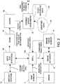
- FIG. 2 is a block diagram identifying some components of a brake health monitoring system in accordance with one embodiment.
- This brake health monitoring system may be used to monitor the health of the wheel brakes of the electric brake system 102 depicted in FIG. 1 , brakes of other electric brake systems having configurations different than what is depicted in FIG. 1 , or brakes of non-electric brake systems.
- brake 2 is of a type that operates by friction in response to the application of a brake force.
- the brake force is applied by a brake actuator 8 in response to a brake force command received from a brake system control unit (BSCU) 110.
- BSCU brake system control unit
- a temperature sensor 4 is operatively coupled to measure the temperature of brake 2 over time during application of brake forces.
- the temperature sensor 4 outputs electrical signals representing the measured brake temperature.
- the temperature sensor 4 may be incorporated in a line replaceable unit (LRU).
- LRU line replaceable unit
- a brake force sensor 6 is operatively coupled to the brake actuator 8 for measuring the surface normal brake force being applied to brake 2.
- brake force sensors such as a resolver to measure brake piston position or a load cell to measure normal force.
- the brake force sensor device electro-mechanics allow for the BSCU to get a reading from the device and convert that data into the measured brake force.
- the measured brake force data generated by brake force sensor 6 may be used to calculate brake output energy in an alternative embodiment (discussed below).
- the brake force sensor 6 may be incorporated in a LRU.
- the BSCU 110 receives the data representing the measured brake temperature from the temperature sensor 4 and the data representing the measured brake force from the brake force sensor 6 and transmits that data to a data bus system 10. In addition, the BSCU 110 transmits electrical signals representing the commanded brake force to the data bus system.
- the aircraft further comprises an aircraft system 12 configured to generate electrical signals representing a measured ground speed of the aircraft and related data and transmit that data to the data bus system 10.
- the data transmitted to the data bus system 10 may be broadcast to all units connected to data bus system 10 in accordance with a communications protocol (e.g., the controller area network communications protocol).
- a communications protocol e.g., the controller area network communications protocol
- One such unit is an aircraft condition monitoring system (ACMS) 14.
- ACMS aircraft condition monitoring system
- the ACMS 14 is a computer system configured to collect, monitor, record and report real-time aircraft system data. For example, other data collected by the ACMS 14 is used to perform cabin pressure and temperature monitoring, hard landing detection, flight crew monitoring, and engine monitoring in addition to many other aircraft performance functions. The reported data is then utilized to analyze aircraft performance and trends in aircraft performance, report significant flight events, and troubleshoot faults.
- the functions of the ACMS 14 may be implemented in software running on a general purpose computer, other embodiments may be implemented in software residing on customized processors or LRUs.
- the ACMS 14 is further configured to output processed data to a digital datalink system for transmission of messages between aircraft and ground stations.
- the digital datalink system is the Aircraft Communications Addressing and Reporting System (ACARS) 16.
- ACARS Aircraft Communications Addressing and Reporting System
- ACARS is a system for transmission of data messages between aircraft and ground stations via radio (VHF or HF) or satellite. ACARS messages are transmitted to and from aircraft before, during and after flights. ACARS is used to send information about the conditions of various aircraft systems and sensors in real-time. For example, the aircraft sends in-flight reports on position, altitude, speed, outside temperature, wind, fuel, engine performance, etc. over ACARS.
- the ACARS 16 comprises an avionics computer called an ACARS Management Unit (MU), which is directly interfaced to a Control Display Unit in the cockpit. There is a datalink interface between the ACARS MU and the flight management system.
- An ACARS message typically comprises a header containing an aircraft identifier, a payload containing aircraft calculated and measured data (in the present case, brake condition data) and a cyclic redundancy check.
- the ACARS 16 broadcasts brake condition reports, which are received by a radio transceiver (not shown in FIG. 2 ).
- the radio transceiver is managed by a ground-based computer system called an Arinc Front End Processor System (not shown in FIG. 2 ), which handles and routes messages.
- brake condition reports from ACARS 16 are routed to a ground-based brake health assessment computer system 18.
- the brake health assessment computer system 18 is configured to process the data in the received brake condition reports using one or more of the brake health monitoring algorithms disclosed below and generate a final assessment of the health of brake 2.
- the brake health assessment computer system 18 is further configured to use weather data 20 and fleet historical data 22 in the course of assessing the health of brake 2.
- the weather data 20 may include ground weather information collected from weather sources, such as, for example, without limitation, the National Oceanic and Atmospheric Administration. More specifically, ground weather information may include information about weather local to a particular operation center, including meteorological conditions pertinent to a particular landing at a particular time and place, such as precipitation, temperature, wind speed and direction.
- the fleet historical data 22 comprises historical brake condition data for a fleet of aircraft, including ranges of expected values of various brake health indicators. Such ranges of expected values are determined based on historical values of brake health indicators for the same brake or similar brakes that were in acceptable condition at the time when those historical values were acquired.
- FIG. 2A is a block diagram identifying components of a brake health assessment computer system 18 suitable for executing the brake health monitoring algorithms disclosed in detail below.
- the brake health assessment computer system 18 comprises a memory device 202 and a processor 204 coupled to memory device 202 for use in executing instructions. More specifically, the brake health assessment computer system 18 configurable to perform one or more operations described herein by programming memory device 202 and/or processor 204.
- processor 204 may be programmed by encoding an operation as one or more executable instructions and by providing the executable instructions in memory device 202.
- Processor 204 may include one or more processing units (e.g., in a multicore configuration).
- processor is not limited to integrated circuits referred to in the art as a computer, but rather broadly refers to a controller, a microcontroller, a microcomputer, a programmable logic controller, an application specific integrated circuit, and other programmable circuits.
- the memory device 202 includes one or more devices (not shown) that enable information such as executable instructions (such as brake health monitoring algorithms) and/or other data to be selectively stored and retrieved.
- data may include, but is not limited to, historical brake condition data, brake condition reports, weather data, aircraft data (including, for example, groundspeed data), modeling data, imaging data, and operational data.
- the brake health assessment computer system 18 is configured to use any algorithm and/or method that enables the methods and systems to function as described herein.
- Memory device 202 may also include one or more non-transitory tangible computer-readable storage media, such as, without limitation, dynamic random access memory, static random access memory, a solid state disk, and/or a hard disk.
- the brake health assessment computer system 18 further comprises a display interface 206 that is coupled to processor 204 for use in presenting information to a user.
- display interface 206 may include a display adapter (not shown) that may couple to a display device 208, such as, without limitation, a cathode ray tube, a liquid crystal display, a light-emitting diode (LED) display, an organic LED display, an "electronic ink” display, and/or a printer.
- a display device 208 such as, without limitation, a cathode ray tube, a liquid crystal display, a light-emitting diode (LED) display, an organic LED display, an "electronic ink” display, and/or a printer.
- the brake health assessment computer system 18, in the exemplary embodiment, further comprises an input interface 212 for receiving input from the user.
- input interface 212 receives information from an input device 210 suitable for use with the methods described herein.
- Input interface 212 is coupled to processor 204 and to input device 210, which may include, for example, a joystick, a keyboard, a pointing device, a mouse, a stylus, a touch sensitive panel (e.g., a touch pad or a touch screen), and/or a position detector.
- the brake health assessment computer system 18 further comprises a communication interface 214 that is coupled to processor 204.
- communication interface 214 communicates with at least one remote device, e.g., a transceiver 216.
- remote device e.g., a transceiver 216.
- communication interface 214 may use, without limitation, a wired network adapter, a wireless network adapter, and/or a mobile telecommunications adapter.
- a network (not shown) used to couple the brake health assessment computer system 18 to the remote device may include, without limitation, the Internet, a local area network (LAN), a wide area network, a wireless LAN, a mesh network, and/or a virtual private network or other suitable communication means.
- the brake health assessment computer system 18 is configured (e.g., by means of executable instructions embodied in a non-transitory tangible computer-readable storage medium, including, without limitation, a storage device and/or a memory device) to perform a brake health monitoring algorithm.
- Various brake health monitoring algorithms which estimate brake input energy using the commanded brake force and measured speed of the aircraft, will now be described in some detail.
- the output energy of the brake is estimated by measuring a change in brake temperature during a time interval.
- the output energy of the brake is estimated by measuring the brake force applied over time.
- a first brake health monitoring algorithm is designed for monitoring a single brake.
- a second brake health monitoring algorithm compares the temperatures in a pair of similar brakes.
- a third brake health monitoring algorithm compares the measured brake temperatures for one brake with selected brake temperature data collected from the same brake during other landings under similar conditions.
- the long-term health of a single brake is determined by relating a calculated braking energy (i.e., the input energy) to a measured thermal energy (i.e., the output energy).
- This method utilizes real system measured parameters related to the amount of thermal energy generated during a braking process.
- the work done by a brake to slow an aircraft is converted into thermal energy through the brake frictional force.
- the amount of work done by a brake is approximately proportional to the measured change in temperature during the braking process. More specifically, the amount of work done by a brake is approximately proportional to the difference between first and second temperature measurement, wherein the first temperature measurement is acquired before the braking process is initiated and the second temperature measurement is acquired after the braking process is terminated.
- the amount of work done by a brake during a braking process is also proportional to the area under the (speed x commanded brake force) power curve for the time interval during which brake force is applied.
- a long-term braking system health factor is derived from the ratio of these values. This term will be monitored over time and changes in the value relate to changes in the braking system, such as brake wear.
- the approximately proportional relationship of the amount of work done by a brake to slow a vehicle (Work MEASURED ) and the measured change in temperature from before ( Temp BEFORE ) and after ( Temp AFTER ) the braking process can be expressed as follows: Work MEASURED ⁇ Temp AFTER ⁇ Temp BEFORE
- the expected amount of work done by a brake to reduce vehicle velocity can be calculated to within a proportionality factor WOW.
- the WOW factor is (0, 1) and merely indicates that the vehicle (e.g., an aircraft) must be on the ground (i.e., weight on wheels) for the calculation.
- the calculated amount of work done can be expressed as follows: Work CALCULATED ⁇ Sum over time F NORMAL ⁇ Speed ⁇ WOW where F NORMAL is the surface normal force and Speed is the ground speed of the vehicle. (The rotational rate of the wheel can be deduced from the groundspeed and wheel size, i.e., the wheel rotation rate is proportional to groundspeed. Because the first algorithm uses proportionality factorization, the exact size of the wheel does not need to be taken into account.)
- a respective set of sensor and command data can be collected over time (i.e., after multiple landings) for each brake on an aircraft. Based on the collected sensor and command data, a respective value of the above-described Single Brake Health Indicator will be calculated for each data set and stored in a database. This stored data can then be selectively processed to determine respective ranges of acceptable values of the Single Brake Health Indicator for each brake. Each range of acceptable values is preferably bounded by an upper threshold value and/or a lower threshold value.
- the long-term health of a single brake is determined by relating a calculated braking energy (i.e., the brake input energy) to a measured thermal energy (i.e., the brake output energy). More specifically, execution of the first brake health monitoring algorithm comprises calculating the brake input energy, calculating the brake output energy and then calculating the ratio of the brake input energy to the brake output energy.
- This method utilizes real system measured parameters related to the amount of thermal energy generated during a braking process. The work done by a brake to slow an aircraft in converted into thermal energy through the brake frictional force. The amount of work done by a brake is approximately proportional to the measured change in temperature during the braking process.
- the amount of work done by a brake is approximately proportional to the difference between first and second temperature measurements, wherein the first temperature measurement is acquired before the braking process is initiated and the second temperature measurement is acquired after the braking process is terminated.
- the amount of work done by a brake during a braking process is also proportional to the area under the (speed times commanded brake force) power curve for the time interval during which brake force is applied.
- a long-term braking system health factor is derived from the ratio of these values. This term will be monitored over time and any changes in value relate to changes in the braking system, such as increased brake wear or other damage.
- the brake condition parameter is measured brake force
- the amount of brake output energy during application of brake forces is estimated by calculating a sum over time of a product of the measured groundspeed of the vehicle and the measured brake force during application of brake forces.
- the applied brake force is measured by the brake force sensor 6 (see FIG. 2 ).
- the long-term brake health for a pair of brakes arranged to apply respective brake forces in a symmetrical manner is determined using only changes in brake temperature.
- This method uses real system measured parameters related to thermal energy generated during a braking process. For example, this method would compare axial pairs and inter-truck and intra-truck brakes. The amount of work done by both brakes during the braking process in a symmetric force application system will be equal. Temperature change is directly related to the work being done.
- the measured change in temperature in one brake should be proportional to the measured change in temperature in the other brake (e.g., TempBrake2 AFTER - TempBrake2 BEFORE ), where the subscripts "BEFORE” and "AFTER” indicate the temperatures before and after the braking process for each brake.
- the respective temperature changes would be equal if the structure from brake surface to measurement location were the same. However, differences in measurement location and structure can create different energy inputs to thermal difference measurements. The result is that the measured thermal difference before and after braking in one brake should be proportional to the measured thermal difference in the other brake.
- This method provides a technique for detecting degradation of one brake relative to the other brake. It will fail if both brakes degrade (e.g., wear) in a similar manner.
- Dual Brake Health Indicator can provide insight into changing brake health.
- respective sets of brake temperature data can be collected over time (i.e., after multiple landings) for each pair of brakes on an aircraft that apply brake forces symmetrically. Based on the collected temperature data, a respective value of the above-described Dual Brake Health Indicator will be calculated for each data set and stored in a database. This stored data can then be selectively processed to determine respective ranges of acceptable values of the Dual Brake Health Indicator for each pair of associated brakes. Each range of acceptable values is preferably bounded by an upper threshold value and/or a lower threshold value.
- the Dual Brake Health Indicator relies on the comparison of historical brake temperature data and brake temperature data acquired during the most recent landing.
- a third brake health monitoring algorithm which filters landing data sets to be more similar and therefore comparable over time is employed.
- the third brake health monitoring algorithm is designed to be used in conjunction with either the first or second brake health monitoring algorithm.
- the third brake health monitoring algorithm can be used to refine other methods for brake health monitoring by adjusting for potential confounders, i.e. other factors that also affect temperature.
- the ideal goal is to conclude that a high temperature is caused by a fault or wear. But the challenge is that other factors also affect temperature. Temperatures from different landings may not be comparable. A high temperature observed in one flight may be due to other factors and not due to a fault.
- the ideal goal is only possible after removing the effect of other factors (confounders) that also affect temperature.
- the procedure involves two steps: (1) first estimate what the temperature would have been if the system were healthy -- based on these other factors, (2) then remove the effect of these other factors by subtracting estimated from observed temperature.
- the estimation can be accomplished in two ways, depending on the number of confounders. If the number is modest, through matching; if the number is higher, through regression. Only healthy examples are included in the pool of matches, and in the training set to estimate the regression.
- the goal is to estimate wear, then choose the healthy examples at a fixed point of wear (early in life, possibly after a suitable break-in period). Otherwise, if detecting a fault (and not wear) is of primary interest, then include as a candidate confounder an indicator for wear such as brake age or usage. Select confounders through subject matter expertise, and also by assessing which candidates help to better predict temperature.
- Examples of potential confounders include both (1) single time measurements (which vary little over the time of a landing), and (2) time series measurements whose profile over a flight can be important.
- Examples of single time measurements include outside air temperature, altitude, time to taxi, length of runway, vertical acceleration at landing (to determine hard landing).
- Examples of time series measurement include longitudinal and lateral accelerations, and braking time sequences such as brake force, ground speed, auto brake commands, thrust reverser, and anti-skid.
- brake manufacturers differ in their way of measuring brake force and comparing with commanded force. This can affect variability of temperatures. Therefore, brake manufacturer should also be a candidate confounder.
- Fitting the model is typically an iterative process. When completed, the model is deployed in the following way. For a new observation, estimate temperature using the fitted regression model and observed confounders. Calculate the residuals: the observed minus the estimated/predicted. This is the difference between observed and what would have been observed if the system were healthy. This controls/normalizes for other factors that affect temperature. If done correctly, the residual is due to fault/wear. A small residual indicates a healthy system, whereas a large residual indicates a fault/wear.
- Matching on confounders is a similar process, and is appropriate for a low number of confounders, or to help choose confounders for the regression approach. Healthy examples are used, and this set should have a distribution of confounders similar to what will be encountered when the system is deployed. The key difference is that instead of fitting a regression model, a distance metric is used to define similarity of matches. A pool of healthy examples is maintained in a database.
- the chosen distance metric is used to find one or more examples in the database that have the most similar confounding variables.
- the corresponding temperature is used as an estimate of what the temperature would have been if healthy, based on the confounding variables.
- the difference from observed is the effect due to a fault/wear.
- FIG. 3 indicates the relationship between FIGS. 3A and 3B , which figures (in conjunction) form a flowchart identifying steps of a process 30 for monitoring the health of brakes on a vehicle in accordance with one advantageous embodiment that employs the first brake health monitoring algorithm disclosed above.
- the process 32 begins when the brake system control unit generates brake force command data representing brake force commands (step 34). Brake forces are applied to the brake in response to the brake force commands (step 36).
- an aircraft system generates groundspeed data representing measured groundspeeds of the vehicle during application of brake forces (step 38).
- brake data representing brake data representing measurements of a condition (e.g., temperature or brake force) of the brake during application of brake forces is generated (step 40).
- the brake force command data, groundspeed data and brake data are collected onboard the vehicle (step 42). Thereafter the collected data is transmitted to a ground-based computer system (step 44).
- the ground-based computer system is configured to perform the following steps: calculate a current value of a brake health indicator that is a ratio of a brake input energy to a brake output energy based on the collected data (step 46 in FIG. 3A ); and determine whether the current value of the brake health indicator is outside a range of expected values or not (step 48 in FIG. 3B ).
- the ground-based computer system is further configured to cease its brake health assessment process (step 50) if a determination is made in step 48 that the current value of the brake health indicator is not outside the range of expected values. Conversely, the ground-based computer system is further configured to generate a flag (step 52) in response to a determination in step 48 that the current value of the brake health indicator is outside the range of expected values.
- An inspection of the brake is performed following generation of the flag (step 54). A determination is then made (based on the inspection results) whether the brake should be replaced or not (step 56). If it is determined that the brake should be replaced, then appropriate steps are taken to replace the brake (step 58). If the brake should not be replaced, a further determination (again based on the inspection results) is made whether the brake should be repaired or not (step 60). If it is determined that the brake should be repaired, not replaced, then appropriate steps are taken to repair the brake (step 62). If it is determined that the brake should be neither replaced nor repaired, then the ground-based computer system will cease its brake health assessment process (step 50).
- FIG. 4 indicates the relationship between FIGS. 4A and 4B , which figures in conjunction form a flowchart identifying steps of a process 70 for monitoring the health of brakes on a vehicle in accordance with another advantageous embodiment that employs the second brake health monitoring algorithm disclosed above.
- the process 72 begins when the brake system control unit generates brake force command data representing brake force commands (step 74). Brake forces are applied to first and second brakes in response to the brake force commands (step 76). First thermal energy data representing an amount of thermal energy produced by the first brake during application of brake forces is generated (step 78a). Similarly, second thermal energy data representing an amount of thermal energy produced by the second brake during application of brake forces is generated (step 78b). The brake force command data, groundspeed data first and second thermal energy data are collected onboard the vehicle (step 80). Thereafter the collected data is transmitted to a ground-based computer system (step 82).
- the ground-based computer system is configured to perform the following steps: calculate a current value of a brake health indicator that is a ratio of the amounts of thermal energy respectively produced by the first and second brakes during application of brake forces (step 84); and determine whether the current value of the brake health indicator is outside a range of expected values or not (step 86).
- the ground-based computer system is further configured to cease its brake health assessment process (step 100) if a determination is made in step 86 that the current value of the brake health indicator is not outside the range of expected values.
- the ground-based computer system is further configured to generate a flag (step 88) in response to a determination in step 86 that the current value of the brake health indicator is outside the range of expected values.
- An inspection of the brakes is performed following generation of the flag (step 90). A determination is then made (based on the inspection results) whether either of the brakes should be replaced or not (step 92). If it is determined that one of the brakes should be replaced, then appropriate steps are taken to replace that brake (step 94). If neither brake should be replaced, a further determination (again based on the inspection results) is made whether one of the brakes should be repaired or not (step 96). If it is determined that one of the brakes should be repaired, then appropriate steps are taken to repair that brake (step 98). If it is determined that neither brake should be replaced nor repaired, then the ground-based computer system will cease its brake health assessment process (step 100).
- computing system comprises one or more of the following: a computer, a processor, a controller, a central processing unit, a microcontroller, a reduced instruction set computer processor, an ASIC, a programmable logic circuit, an FPGA, a digital signal processor, and/or any other circuit or processing device capable of executing the functions described herein.
- a computing system may comprise multiple microcontrollers or multiple processors which communicate via a network or bus.
- ⁇ As used herein, the terms “computer” and “processor” both refer to devices having a processing unit (e.g., a central processing unit) and some form of memory (i.e., computer-readable medium) for storing a program which is readable by the processing unit.
- a processing unit e.g., a central processing unit
- memory i.e., computer-readable medium
- the methods described herein may be encoded as executable instructions embodied in a non-transitory tangible computer-readable storage medium, including, without limitation, a storage device and/or a memory device. Such instructions, when executed by a processing or computing system, cause the system device to perform at least a portion of the methods described herein.
Claims (15)
- Procédé de surveillance d'un état de freins sur un véhicule, comprenant :(a) la génération (74) de données de commande de force de freinage représentant des commandes de force de freinage ;(b) l'application (76) de forces de freinage à des premier et second freins (2) en réponse aux commandes de force de freinage ;(c) la génération (78a) de premières données d'énergie thermique représentant une quantité d'énergie thermique produite par le premier frein au cours d'une application de forces de freinage ;(d) la génération (78b) de secondes données d'énergie thermique représentant une quantité d'énergie thermique produite par le second frein au cours d'une application de forces de freinage ;(e) la collecte (80) des premières et secondes données d'énergie thermique à bord du véhicule pour former des données de température collectées ;(f) la transmission (82) des premières et secondes données d'énergie thermique collectées à un système informatique qui est configuré pour réaliser les étapes (g), (h) et (i) ;(g) le calcul (84) d'une valeur courante d'un indicateur d'état de frein qui est un rapport des quantités d'énergie thermique produite respectivement par les premier et second freins au cours d'une application de forces de freinage ;(h) la détermination (86) si la valeur courante de l'indicateur d'état de frein est ou non à l'extérieur d'une plage de valeurs attendues ; et(i) la génération (88) d'un drapeau en réponse à une détermination à l'étape (h) que la valeur courante de l'indicateur d'état de frein est à l'extérieur de la plage de valeurs attendues.
- Procédé selon la revendication 1, comprenant en outre :(j) la réalisation (90) d'une inspection des premier et second freins à la suite d'une génération du drapeau ; et(k) la détermination (92, 96) si l'un des premier et second freins doit ou non être réparé ou remplacé sur la base de résultats de l'inspection.
- Procédé selon la revendication 2, comprenant en outre la réparation ou le remplacement du premier ou second frein sur la base de résultats de l'étape (k).
- Procédé selon l'une quelconque des revendications 1 à 3, dans lequel les premières données d'énergie thermique comprennent des premières données de température de frein représentant un changement de température dans le premier frein au cours d'une application de forces de freinage, les secondes données d'énergie thermique comprennent des secondes données de température de frein représentant un changement de température dans le second frein au cours d'une application de forces de freinage, et le calcul de la valeur courante de l'indicateur d'état de frein comprend le calcul d'un rapport du changement de température dans le premier frein et du changement de température dans le second frein.
- Procédé selon l'une quelconque des revendications 1 à 4, comprenant en outre la suppression d'effets d'autres facteurs qui affectent également la température.
- Procédé selon l'une quelconque des revendications 1 à 5, dans lequel les premier et second freins sont configurés et positionnés pour produire des forces de freinage appliquées symétriquement.
- Procédé selon l'une quelconque des revendications 1 à 6, dans lequel les valeurs attendues sont dérivées de données historiques d'état de frein acquises dans des conditions d'atterrissage similaires pour le même frein ou des freins similaires.
- Système de surveillance d'un état de freins sur un véhicule, comprenant un système informatique configuré pour réaliser les opérations suivantes :la réception de premières données d'énergie thermique représentant une quantité d'énergie thermique produite par un premier frein au cours d'une application de forces de freinage ;la réception de secondes données d'énergie thermique représentant une quantité d'énergie thermique produite par le second frein au cours d'une application de forces de freinage ;le calcul (84) d'une valeur courante d'un indicateur d'état de frein qui est un rapport des quantités d'énergie thermique produite respectivement par les premier et second freins au cours d'une application de forces de freinage ;la détermination (86) si la valeur courante de l'indicateur d'état de frein est ou non à l'extérieur d'une plage de valeurs attendues ; etla génération (88) d'un drapeau en réponse à une détermination que la valeur courante de l'indicateur d'état de frein est à l'extérieur de la plage de valeurs attendues.
- Système selon la revendication 8, dans lequel les premières données d'énergie thermique comprennent des premières données de température de frein représentant un changement de température dans le premier frein au cours d'une application de forces de freinage, les secondes données d'énergie thermique comprennent des secondes données de température de frein représentant un changement de température dans le second frein au cours d'une application de forces de freinage, et le calcul de la valeur courante de l'indicateur d'état de frein comprend le calcul d'un rapport du changement de température dans le premier frein et du changement de température dans le second frein.
- Système selon la revendication 8 ou 9, dans lequel les premier et second freins sont configurés et positionnés pour produire des forces de freinage appliquées symétriquement.
- Système selon l'une quelconque des revendications 8 à 10, dans lequel le système informatique comprend un système de surveillance d'état d'aéronef (14) et un système informatique d'évaluation d'état de frein (18).
- Système selon la revendication 11, dans lequel le système de surveillance d'état d'aéronef est configuré pour collecter, surveiller, enregistrer et rapporter des données de système d'aéronef en temps réel.
- Système selon la revendication 11 ou 12, dans lequel le système informatique d'évaluation d'état de frein (18) est configuré pour traiter un rapport d'état de frein.
- Système selon la revendication 13, dans lequel le système informatique d'évaluation d'état de frein est en outre configuré pour générer une évaluation finale de l'état de frein.
- Système selon la revendication 14, dans lequel le système informatique d'évaluation d'état de frein est en outre configuré pour utiliser des données météorologiques (20) et des données historiques de flotte (22) au cours de l'évaluation de l'état de frein.
Applications Claiming Priority (2)
| Application Number | Priority Date | Filing Date | Title |
|---|---|---|---|
| US15/489,877 US10800392B2 (en) | 2017-04-18 | 2017-04-18 | Brake health indicator systems using input and output energy |
| EP18157763.6A EP3392107B1 (fr) | 2017-04-18 | 2018-02-21 | Systèmes indicateurs de la santé de freins au moyen de l'énergie d'entrée et de sortie |
Related Parent Applications (2)
| Application Number | Title | Priority Date | Filing Date |
|---|---|---|---|
| EP18157763.6A Division EP3392107B1 (fr) | 2017-04-18 | 2018-02-21 | Systèmes indicateurs de la santé de freins au moyen de l'énergie d'entrée et de sortie |
| EP18157763.6A Division-Into EP3392107B1 (fr) | 2017-04-18 | 2018-02-21 | Systèmes indicateurs de la santé de freins au moyen de l'énergie d'entrée et de sortie |
Publications (2)
| Publication Number | Publication Date |
|---|---|
| EP3689692A1 EP3689692A1 (fr) | 2020-08-05 |
| EP3689692B1 true EP3689692B1 (fr) | 2021-10-27 |
Family
ID=61258151
Family Applications (2)
| Application Number | Title | Priority Date | Filing Date |
|---|---|---|---|
| EP20165084.3A Active EP3689692B1 (fr) | 2017-04-18 | 2018-02-21 | Systèmes indicateurs de la santé de freins au moyen de l'énergie d'entrée et de sortie |
| EP18157763.6A Active EP3392107B1 (fr) | 2017-04-18 | 2018-02-21 | Systèmes indicateurs de la santé de freins au moyen de l'énergie d'entrée et de sortie |
Family Applications After (1)
| Application Number | Title | Priority Date | Filing Date |
|---|---|---|---|
| EP18157763.6A Active EP3392107B1 (fr) | 2017-04-18 | 2018-02-21 | Systèmes indicateurs de la santé de freins au moyen de l'énergie d'entrée et de sortie |
Country Status (5)
| Country | Link |
|---|---|
| US (1) | US10800392B2 (fr) |
| EP (2) | EP3689692B1 (fr) |
| JP (1) | JP7098395B2 (fr) |
| CN (1) | CN108725417B (fr) |
| SG (1) | SG10201802524VA (fr) |
Families Citing this family (18)
| Publication number | Priority date | Publication date | Assignee | Title |
|---|---|---|---|---|
| GB2554097A (en) * | 2016-09-20 | 2018-03-28 | Airbus Operations Ltd | Brake wear reduction apparatus |
| JP6822355B2 (ja) * | 2017-09-06 | 2021-01-27 | トヨタ自動車株式会社 | 制動力制御システム |
| US11598880B2 (en) * | 2018-10-04 | 2023-03-07 | The Boeing Company | Detecting fault states of an aircraft |
| CN111497812A (zh) * | 2019-01-31 | 2020-08-07 | 天津所托瑞安汽车科技有限公司 | 一种基于平台的车辆刹车系统监测方法 |
| EP3753794A1 (fr) * | 2019-06-19 | 2020-12-23 | KNORR-BREMSE Systeme für Nutzfahrzeuge GmbH | Procédé et appareil de surveillance d'une performance de freinage d'un véhicule |
| DE102019212076A1 (de) * | 2019-08-13 | 2021-02-18 | Audi Ag | Verfahren zum Ermitteln einer benutzerspezifischen Konfiguration einer Bremsvorrichtung sowie ein Kraftfahrzeug und ein computerlesbares Speichermedium hierzu |
| CN110901624B (zh) * | 2019-12-06 | 2021-03-26 | 中车株洲电力机车有限公司 | 摩擦制动故障检测方法、装置、可读存储介质及控制器 |
| CN111047916B (zh) * | 2019-12-30 | 2022-04-12 | 四川函钛科技有限公司 | 一种基于qar曲线面积特征的重着陆风险识别方法 |
| EP3862238B1 (fr) | 2020-02-05 | 2023-06-07 | Goodrich Corporation | Procédés directs et indirects pour l'estimation de l'usure des freins d'avion |
| EP3862737A1 (fr) | 2020-02-05 | 2021-08-11 | Goodrich Corporation | Estimation de la température de frein d'avion à base de modèle |
| EP3862835B1 (fr) | 2020-02-10 | 2023-10-25 | Volocopter GmbH | Procédé et système de surveillance de l'état d'un aéronef à décollage et à atterrissage verticaux (adav) |
| US11505173B2 (en) * | 2020-03-13 | 2022-11-22 | Goodrich Corporation | Systems and methods for brake health monitoring |
| US11808882B2 (en) * | 2020-11-20 | 2023-11-07 | Bae Systems Information And Electronic Systems Integration Inc. | Radar electronic countermeasures without a threat database |
| US11733349B2 (en) | 2020-11-20 | 2023-08-22 | Bae Systems Information And Electronic Systems Integration Inc. | Realtime electronic countermeasure optimization |
| US11938911B2 (en) | 2021-04-08 | 2024-03-26 | Arvinmeritor Technology, Llc | Brake system and method of monitoring |
| CN114776742B (zh) * | 2022-04-27 | 2023-06-30 | 江西五十铃汽车有限公司 | 基于车联网平台的汽车刹车片的更换提醒方法及系统 |
| US11702193B1 (en) | 2022-04-28 | 2023-07-18 | Beta Air, Llc | Systems and methods for an electric vertical takeoff and landing aircraft braking system |
| CN115163708B (zh) * | 2022-06-21 | 2023-07-25 | 东风柳州汽车有限公司 | 一种制动盘温度的实时检测方法和装置 |
Family Cites Families (23)
| Publication number | Priority date | Publication date | Assignee | Title |
|---|---|---|---|---|
| DE3502050A1 (de) * | 1985-01-23 | 1986-07-24 | Wabco Westinghouse Fahrzeugbremsen GmbH, 3000 Hannover | Einrichtung zum messen und/oder regeln einer bremskraft und/oder eines bremsmomentes |
| US4845468A (en) * | 1988-01-21 | 1989-07-04 | Dresser Industries, Inc. | Brake condition warning system |
| DE19536619B4 (de) * | 1995-09-30 | 2006-01-26 | Robert Bosch Gmbh | Ventil für eine hydraulische Bremsanlage für Kraftfahrzeuge |
| US5909171A (en) * | 1997-07-17 | 1999-06-01 | Meritor Heavy Vehicle Systems, L L C | Temperature sensing brake lining wear indicator |
| JP3585707B2 (ja) * | 1997-08-29 | 2004-11-04 | 本田技研工業株式会社 | 車両におけるブレーキ摩擦材の温度推定方法 |
| GB0019250D0 (en) | 2000-08-04 | 2000-09-27 | Dunlop Aerospace Ltd | Monitoring brake application |
| DE10105638B4 (de) | 2001-02-08 | 2011-04-21 | Volkswagen Ag | Verfahren zum Schutz der Bremsen eines Kraftfahrzeugs vor einer thermischen Überbeanspruchung |
| DE10208961B4 (de) * | 2002-02-28 | 2006-12-28 | Audi Ag | Verschleißerkennung bei Kraftfahrzeugen |
| EP1340926A3 (fr) * | 2002-02-28 | 2003-12-03 | Audi Ag | Détection de variation de propriétés et/ou de l'usure des véhicules |
| CN2541279Y (zh) * | 2002-05-10 | 2003-03-26 | 亚星-奔驰有限公司 | 汽车制动器的散热装置 |
| DE10259529B4 (de) * | 2002-12-19 | 2005-02-17 | Daimlerchrysler Ag | Verfahren zur Ermittlung eines Bremsenzustands |
| US7618100B2 (en) | 2006-12-13 | 2009-11-17 | The Boeing Company | Braking interlock for an electric brake system of an aircraft |
| EP2060456B1 (fr) | 2007-11-14 | 2013-03-27 | Goodrich Corporation | Algorithme pour déterminer le refroidissement de roue et de frein |
| JP4998344B2 (ja) * | 2008-03-19 | 2012-08-15 | 株式会社アドヴィックス | 駐車ブレーキ制御装置 |
| US8712634B2 (en) | 2010-08-11 | 2014-04-29 | The Boeing Company | System and method to assess and report the health of landing gear related components |
| FR2965873B1 (fr) | 2010-10-06 | 2012-11-30 | Peugeot Citroen Automobiles Sa | Procede et dispositif pour la detection d'une surchauffe transitoire locale dans un composant d'un systeme de freinage |
| GB201021545D0 (en) * | 2010-12-21 | 2011-02-02 | Airbus Operations Ltd | A method of monitoring aircraft brake performance and apparatus for performing such a method |
| JP5624531B2 (ja) * | 2011-09-29 | 2014-11-12 | 株式会社アドヴィックス | 車両の制動制御装置 |
| JP6262993B2 (ja) * | 2013-10-31 | 2018-01-17 | 日立オートモティブシステムズ株式会社 | ブレーキ装置 |
| TW201612434A (en) * | 2014-09-23 | 2016-04-01 | Univ Chienkuo Technology | Ventilated brake disc of high-efficiency thermoelectric conversion system |
| US9738264B2 (en) | 2015-01-22 | 2017-08-22 | Goodrich Corporation | Brake cooling estimation methods and systems |
| US10570974B2 (en) | 2015-04-17 | 2020-02-25 | Goodrich Corporation | Brake position and wear detection systems and methods |
| US9592815B2 (en) | 2015-04-29 | 2017-03-14 | New York Air Brake, LLC | Train brake safety monitoring and fault action system |
-
2017
- 2017-04-18 US US15/489,877 patent/US10800392B2/en active Active
-
2018
- 2018-02-21 EP EP20165084.3A patent/EP3689692B1/fr active Active
- 2018-02-21 EP EP18157763.6A patent/EP3392107B1/fr active Active
- 2018-03-27 SG SG10201802524VA patent/SG10201802524VA/en unknown
- 2018-04-13 CN CN201810328862.5A patent/CN108725417B/zh active Active
- 2018-04-16 JP JP2018078489A patent/JP7098395B2/ja active Active
Also Published As
| Publication number | Publication date |
|---|---|
| JP2019001452A (ja) | 2019-01-10 |
| CN108725417A (zh) | 2018-11-02 |
| US20180297573A1 (en) | 2018-10-18 |
| EP3392107A3 (fr) | 2018-12-05 |
| SG10201802524VA (en) | 2018-11-29 |
| EP3392107B1 (fr) | 2020-06-17 |
| JP7098395B2 (ja) | 2022-07-11 |
| EP3689692A1 (fr) | 2020-08-05 |
| EP3392107A2 (fr) | 2018-10-24 |
| CN108725417B (zh) | 2022-07-22 |
| US10800392B2 (en) | 2020-10-13 |
Similar Documents
| Publication | Publication Date | Title |
|---|---|---|
| EP3689692B1 (fr) | Systèmes indicateurs de la santé de freins au moyen de l'énergie d'entrée et de sortie | |
| CN108382384B (zh) | 基于制动器扭矩和温度的故障检测 | |
| US9811950B2 (en) | Aircraft electric taxi system diagnostic and prognostic evaluation system and method | |
| US7086503B2 (en) | Brake condition monitoring | |
| EP3296170B1 (fr) | Appareil de réduction de l'usure des freins | |
| US20220350325A1 (en) | Predicting the life of consumable components | |
| JP2017515716A (ja) | ブレーキ制御システムを用いて滑走路状態を報告する方法 | |
| AU2001278582A1 (en) | Brake condition monitoring | |
| EP3190017B1 (fr) | Détection de comportement anormal de frein | |
| US20170326927A1 (en) | Tyre deflection monitoring | |
| EP2621741B1 (fr) | Systeme de surveillance de pneumatiques par rayon laser | |
| WO2022086794A1 (fr) | Système amélioré permettant de rapporter des états de piste d'aéronef | |
| CN111566575B (zh) | 预测组件的一个或多个设备项工作异常的方法 | |
| US20220119128A1 (en) | System and method to assess and report runway conditions |
Legal Events
| Date | Code | Title | Description |
|---|---|---|---|
| PUAI | Public reference made under article 153(3) epc to a published international application that has entered the european phase |
Free format text: ORIGINAL CODE: 0009012 |
|
| STAA | Information on the status of an ep patent application or granted ep patent |
Free format text: STATUS: REQUEST FOR EXAMINATION WAS MADE |
|
| 17P | Request for examination filed |
Effective date: 20200324 |
|
| AC | Divisional application: reference to earlier application |
Ref document number: 3392107 Country of ref document: EP Kind code of ref document: P |
|
| AK | Designated contracting states |
Kind code of ref document: A1 Designated state(s): AL AT BE BG CH CY CZ DE DK EE ES FI FR GB GR HR HU IE IS IT LI LT LU LV MC MK MT NL NO PL PT RO RS SE SI SK SM TR |
|
| GRAP | Despatch of communication of intention to grant a patent |
Free format text: ORIGINAL CODE: EPIDOSNIGR1 |
|
| STAA | Information on the status of an ep patent application or granted ep patent |
Free format text: STATUS: GRANT OF PATENT IS INTENDED |
|
| INTG | Intention to grant announced |
Effective date: 20210302 |
|
| GRAJ | Information related to disapproval of communication of intention to grant by the applicant or resumption of examination proceedings by the epo deleted |
Free format text: ORIGINAL CODE: EPIDOSDIGR1 |
|
| STAA | Information on the status of an ep patent application or granted ep patent |
Free format text: STATUS: REQUEST FOR EXAMINATION WAS MADE |
|
| INTC | Intention to grant announced (deleted) | ||
| GRAP | Despatch of communication of intention to grant a patent |
Free format text: ORIGINAL CODE: EPIDOSNIGR1 |
|
| STAA | Information on the status of an ep patent application or granted ep patent |
Free format text: STATUS: GRANT OF PATENT IS INTENDED |
|
| INTG | Intention to grant announced |
Effective date: 20210707 |
|
| GRAS | Grant fee paid |
Free format text: ORIGINAL CODE: EPIDOSNIGR3 |
|
| GRAA | (expected) grant |
Free format text: ORIGINAL CODE: 0009210 |
|
| STAA | Information on the status of an ep patent application or granted ep patent |
Free format text: STATUS: THE PATENT HAS BEEN GRANTED |
|
| AC | Divisional application: reference to earlier application |
Ref document number: 3392107 Country of ref document: EP Kind code of ref document: P |
|
| AK | Designated contracting states |
Kind code of ref document: B1 Designated state(s): AL AT BE BG CH CY CZ DE DK EE ES FI FR GB GR HR HU IE IS IT LI LT LU LV MC MK MT NL NO PL PT RO RS SE SI SK SM TR |
|
| REG | Reference to a national code |
Ref country code: GB Ref legal event code: FG4D |
|
| REG | Reference to a national code |
Ref country code: CH Ref legal event code: EP |
|
| REG | Reference to a national code |
Ref country code: AT Ref legal event code: REF Ref document number: 1441519 Country of ref document: AT Kind code of ref document: T Effective date: 20211115 |
|
| REG | Reference to a national code |
Ref country code: DE Ref legal event code: R096 Ref document number: 602018025936 Country of ref document: DE |
|
| REG | Reference to a national code |
Ref country code: IE Ref legal event code: FG4D |
|
| REG | Reference to a national code |
Ref country code: LT Ref legal event code: MG9D |
|
| REG | Reference to a national code |
Ref country code: NL Ref legal event code: MP Effective date: 20211027 |
|
| REG | Reference to a national code |
Ref country code: AT Ref legal event code: MK05 Ref document number: 1441519 Country of ref document: AT Kind code of ref document: T Effective date: 20211027 |
|
| PG25 | Lapsed in a contracting state [announced via postgrant information from national office to epo] |
Ref country code: RS Free format text: LAPSE BECAUSE OF FAILURE TO SUBMIT A TRANSLATION OF THE DESCRIPTION OR TO PAY THE FEE WITHIN THE PRESCRIBED TIME-LIMIT Effective date: 20211027 Ref country code: LT Free format text: LAPSE BECAUSE OF FAILURE TO SUBMIT A TRANSLATION OF THE DESCRIPTION OR TO PAY THE FEE WITHIN THE PRESCRIBED TIME-LIMIT Effective date: 20211027 Ref country code: FI Free format text: LAPSE BECAUSE OF FAILURE TO SUBMIT A TRANSLATION OF THE DESCRIPTION OR TO PAY THE FEE WITHIN THE PRESCRIBED TIME-LIMIT Effective date: 20211027 Ref country code: BG Free format text: LAPSE BECAUSE OF FAILURE TO SUBMIT A TRANSLATION OF THE DESCRIPTION OR TO PAY THE FEE WITHIN THE PRESCRIBED TIME-LIMIT Effective date: 20220127 Ref country code: AT Free format text: LAPSE BECAUSE OF FAILURE TO SUBMIT A TRANSLATION OF THE DESCRIPTION OR TO PAY THE FEE WITHIN THE PRESCRIBED TIME-LIMIT Effective date: 20211027 |
|
| PG25 | Lapsed in a contracting state [announced via postgrant information from national office to epo] |
Ref country code: IS Free format text: LAPSE BECAUSE OF FAILURE TO SUBMIT A TRANSLATION OF THE DESCRIPTION OR TO PAY THE FEE WITHIN THE PRESCRIBED TIME-LIMIT Effective date: 20220227 Ref country code: SE Free format text: LAPSE BECAUSE OF FAILURE TO SUBMIT A TRANSLATION OF THE DESCRIPTION OR TO PAY THE FEE WITHIN THE PRESCRIBED TIME-LIMIT Effective date: 20211027 Ref country code: PT Free format text: LAPSE BECAUSE OF FAILURE TO SUBMIT A TRANSLATION OF THE DESCRIPTION OR TO PAY THE FEE WITHIN THE PRESCRIBED TIME-LIMIT Effective date: 20220228 Ref country code: PL Free format text: LAPSE BECAUSE OF FAILURE TO SUBMIT A TRANSLATION OF THE DESCRIPTION OR TO PAY THE FEE WITHIN THE PRESCRIBED TIME-LIMIT Effective date: 20211027 Ref country code: NO Free format text: LAPSE BECAUSE OF FAILURE TO SUBMIT A TRANSLATION OF THE DESCRIPTION OR TO PAY THE FEE WITHIN THE PRESCRIBED TIME-LIMIT Effective date: 20220127 Ref country code: NL Free format text: LAPSE BECAUSE OF FAILURE TO SUBMIT A TRANSLATION OF THE DESCRIPTION OR TO PAY THE FEE WITHIN THE PRESCRIBED TIME-LIMIT Effective date: 20211027 Ref country code: LV Free format text: LAPSE BECAUSE OF FAILURE TO SUBMIT A TRANSLATION OF THE DESCRIPTION OR TO PAY THE FEE WITHIN THE PRESCRIBED TIME-LIMIT Effective date: 20211027 Ref country code: HR Free format text: LAPSE BECAUSE OF FAILURE TO SUBMIT A TRANSLATION OF THE DESCRIPTION OR TO PAY THE FEE WITHIN THE PRESCRIBED TIME-LIMIT Effective date: 20211027 Ref country code: GR Free format text: LAPSE BECAUSE OF FAILURE TO SUBMIT A TRANSLATION OF THE DESCRIPTION OR TO PAY THE FEE WITHIN THE PRESCRIBED TIME-LIMIT Effective date: 20220128 Ref country code: ES Free format text: LAPSE BECAUSE OF FAILURE TO SUBMIT A TRANSLATION OF THE DESCRIPTION OR TO PAY THE FEE WITHIN THE PRESCRIBED TIME-LIMIT Effective date: 20211027 |
|
| REG | Reference to a national code |
Ref country code: DE Ref legal event code: R097 Ref document number: 602018025936 Country of ref document: DE |
|
| PG25 | Lapsed in a contracting state [announced via postgrant information from national office to epo] |
Ref country code: SM Free format text: LAPSE BECAUSE OF FAILURE TO SUBMIT A TRANSLATION OF THE DESCRIPTION OR TO PAY THE FEE WITHIN THE PRESCRIBED TIME-LIMIT Effective date: 20211027 Ref country code: SK Free format text: LAPSE BECAUSE OF FAILURE TO SUBMIT A TRANSLATION OF THE DESCRIPTION OR TO PAY THE FEE WITHIN THE PRESCRIBED TIME-LIMIT Effective date: 20211027 Ref country code: RO Free format text: LAPSE BECAUSE OF FAILURE TO SUBMIT A TRANSLATION OF THE DESCRIPTION OR TO PAY THE FEE WITHIN THE PRESCRIBED TIME-LIMIT Effective date: 20211027 Ref country code: EE Free format text: LAPSE BECAUSE OF FAILURE TO SUBMIT A TRANSLATION OF THE DESCRIPTION OR TO PAY THE FEE WITHIN THE PRESCRIBED TIME-LIMIT Effective date: 20211027 Ref country code: DK Free format text: LAPSE BECAUSE OF FAILURE TO SUBMIT A TRANSLATION OF THE DESCRIPTION OR TO PAY THE FEE WITHIN THE PRESCRIBED TIME-LIMIT Effective date: 20211027 Ref country code: CZ Free format text: LAPSE BECAUSE OF FAILURE TO SUBMIT A TRANSLATION OF THE DESCRIPTION OR TO PAY THE FEE WITHIN THE PRESCRIBED TIME-LIMIT Effective date: 20211027 |
|
| PLBE | No opposition filed within time limit |
Free format text: ORIGINAL CODE: 0009261 |
|
| STAA | Information on the status of an ep patent application or granted ep patent |
Free format text: STATUS: NO OPPOSITION FILED WITHIN TIME LIMIT |
|
| PG25 | Lapsed in a contracting state [announced via postgrant information from national office to epo] |
Ref country code: MC Free format text: LAPSE BECAUSE OF FAILURE TO SUBMIT A TRANSLATION OF THE DESCRIPTION OR TO PAY THE FEE WITHIN THE PRESCRIBED TIME-LIMIT Effective date: 20211027 |
|
| 26N | No opposition filed |
Effective date: 20220728 |
|
| REG | Reference to a national code |
Ref country code: CH Ref legal event code: PL |
|
| REG | Reference to a national code |
Ref country code: BE Ref legal event code: MM Effective date: 20220228 |
|
| PG25 | Lapsed in a contracting state [announced via postgrant information from national office to epo] |
Ref country code: LU Free format text: LAPSE BECAUSE OF NON-PAYMENT OF DUE FEES Effective date: 20220221 Ref country code: AL Free format text: LAPSE BECAUSE OF FAILURE TO SUBMIT A TRANSLATION OF THE DESCRIPTION OR TO PAY THE FEE WITHIN THE PRESCRIBED TIME-LIMIT Effective date: 20211027 |
|
| PG25 | Lapsed in a contracting state [announced via postgrant information from national office to epo] |
Ref country code: SI Free format text: LAPSE BECAUSE OF FAILURE TO SUBMIT A TRANSLATION OF THE DESCRIPTION OR TO PAY THE FEE WITHIN THE PRESCRIBED TIME-LIMIT Effective date: 20211027 |
|
| PG25 | Lapsed in a contracting state [announced via postgrant information from national office to epo] |
Ref country code: LI Free format text: LAPSE BECAUSE OF NON-PAYMENT OF DUE FEES Effective date: 20220228 Ref country code: IE Free format text: LAPSE BECAUSE OF NON-PAYMENT OF DUE FEES Effective date: 20220221 Ref country code: CH Free format text: LAPSE BECAUSE OF NON-PAYMENT OF DUE FEES Effective date: 20220228 |
|
| PG25 | Lapsed in a contracting state [announced via postgrant information from national office to epo] |
Ref country code: BE Free format text: LAPSE BECAUSE OF NON-PAYMENT OF DUE FEES Effective date: 20220228 |
|
| PGFP | Annual fee paid to national office [announced via postgrant information from national office to epo] |
Ref country code: FR Payment date: 20230223 Year of fee payment: 6 |
|
| PG25 | Lapsed in a contracting state [announced via postgrant information from national office to epo] |
Ref country code: IT Free format text: LAPSE BECAUSE OF FAILURE TO SUBMIT A TRANSLATION OF THE DESCRIPTION OR TO PAY THE FEE WITHIN THE PRESCRIBED TIME-LIMIT Effective date: 20211027 |
|
| P01 | Opt-out of the competence of the unified patent court (upc) registered |
Effective date: 20230516 |
|
| PG25 | Lapsed in a contracting state [announced via postgrant information from national office to epo] |
Ref country code: MK Free format text: LAPSE BECAUSE OF FAILURE TO SUBMIT A TRANSLATION OF THE DESCRIPTION OR TO PAY THE FEE WITHIN THE PRESCRIBED TIME-LIMIT Effective date: 20211027 Ref country code: CY Free format text: LAPSE BECAUSE OF FAILURE TO SUBMIT A TRANSLATION OF THE DESCRIPTION OR TO PAY THE FEE WITHIN THE PRESCRIBED TIME-LIMIT Effective date: 20211027 |
|
| PGFP | Annual fee paid to national office [announced via postgrant information from national office to epo] |
Ref country code: DE Payment date: 20240228 Year of fee payment: 7 Ref country code: GB Payment date: 20240227 Year of fee payment: 7 |