EP3689619A1 - Verfahren zum bedrucken einer oberfläche mit einem druckmuster und dazugehörige druckvorrichtung - Google Patents
Verfahren zum bedrucken einer oberfläche mit einem druckmuster und dazugehörige druckvorrichtung Download PDFInfo
- Publication number
- EP3689619A1 EP3689619A1 EP19020576.5A EP19020576A EP3689619A1 EP 3689619 A1 EP3689619 A1 EP 3689619A1 EP 19020576 A EP19020576 A EP 19020576A EP 3689619 A1 EP3689619 A1 EP 3689619A1
- Authority
- EP
- European Patent Office
- Prior art keywords
- printing
- area
- pattern
- print pattern
- Prior art date
- Legal status (The legal status is an assumption and is not a legal conclusion. Google has not performed a legal analysis and makes no representation as to the accuracy of the status listed.)
- Granted
Links
Images
Classifications
-
- B—PERFORMING OPERATIONS; TRANSPORTING
- B41—PRINTING; LINING MACHINES; TYPEWRITERS; STAMPS
- B41M—PRINTING, DUPLICATING, MARKING, OR COPYING PROCESSES; COLOUR PRINTING
- B41M5/00—Duplicating or marking methods; Sheet materials for use therein
-
- B—PERFORMING OPERATIONS; TRANSPORTING
- B41—PRINTING; LINING MACHINES; TYPEWRITERS; STAMPS
- B41M—PRINTING, DUPLICATING, MARKING, OR COPYING PROCESSES; COLOUR PRINTING
- B41M3/00—Printing processes to produce particular kinds of printed work, e.g. patterns
-
- B—PERFORMING OPERATIONS; TRANSPORTING
- B05—SPRAYING OR ATOMISING IN GENERAL; APPLYING FLUENT MATERIALS TO SURFACES, IN GENERAL
- B05C—APPARATUS FOR APPLYING FLUENT MATERIALS TO SURFACES, IN GENERAL
- B05C5/00—Apparatus in which liquid or other fluent material is projected, poured or allowed to flow on to the surface of the work
- B05C5/02—Apparatus in which liquid or other fluent material is projected, poured or allowed to flow on to the surface of the work the liquid or other fluent material being discharged through an outlet orifice by pressure, e.g. from an outlet device in contact or almost in contact, with the work
- B05C5/0208—Apparatus in which liquid or other fluent material is projected, poured or allowed to flow on to the surface of the work the liquid or other fluent material being discharged through an outlet orifice by pressure, e.g. from an outlet device in contact or almost in contact, with the work for applying liquid or other fluent material to separate articles
-
- B—PERFORMING OPERATIONS; TRANSPORTING
- B05—SPRAYING OR ATOMISING IN GENERAL; APPLYING FLUENT MATERIALS TO SURFACES, IN GENERAL
- B05C—APPARATUS FOR APPLYING FLUENT MATERIALS TO SURFACES, IN GENERAL
- B05C9/00—Apparatus or plant for applying liquid or other fluent material to surfaces by means not covered by any preceding group, or in which the means of applying the liquid or other fluent material is not important
- B05C9/08—Apparatus or plant for applying liquid or other fluent material to surfaces by means not covered by any preceding group, or in which the means of applying the liquid or other fluent material is not important for applying liquid or other fluent material and performing an auxiliary operation
- B05C9/12—Apparatus or plant for applying liquid or other fluent material to surfaces by means not covered by any preceding group, or in which the means of applying the liquid or other fluent material is not important for applying liquid or other fluent material and performing an auxiliary operation the auxiliary operation being performed after the application
-
- B—PERFORMING OPERATIONS; TRANSPORTING
- B05—SPRAYING OR ATOMISING IN GENERAL; APPLYING FLUENT MATERIALS TO SURFACES, IN GENERAL
- B05D—PROCESSES FOR APPLYING FLUENT MATERIALS TO SURFACES, IN GENERAL
- B05D3/00—Pretreatment of surfaces to which liquids or other fluent materials are to be applied; After-treatment of applied coatings, e.g. intermediate treating of an applied coating preparatory to subsequent applications of liquids or other fluent materials
- B05D3/06—Pretreatment of surfaces to which liquids or other fluent materials are to be applied; After-treatment of applied coatings, e.g. intermediate treating of an applied coating preparatory to subsequent applications of liquids or other fluent materials by exposure to radiation
-
- B—PERFORMING OPERATIONS; TRANSPORTING
- B41—PRINTING; LINING MACHINES; TYPEWRITERS; STAMPS
- B41J—TYPEWRITERS; SELECTIVE PRINTING MECHANISMS, i.e. MECHANISMS PRINTING OTHERWISE THAN FROM A FORME; CORRECTION OF TYPOGRAPHICAL ERRORS
- B41J11/00—Devices or arrangements of selective printing mechanisms, e.g. ink-jet printers or thermal printers, for supporting or handling copy material in sheet or web form
- B41J11/0015—Devices or arrangements of selective printing mechanisms, e.g. ink-jet printers or thermal printers, for supporting or handling copy material in sheet or web form for treating before, during or after printing or for uniform coating or laminating the copy material before or after printing
- B41J11/002—Curing or drying the ink on the copy materials, e.g. by heating or irradiating
- B41J11/0021—Curing or drying the ink on the copy materials, e.g. by heating or irradiating using irradiation
- B41J11/00214—Curing or drying the ink on the copy materials, e.g. by heating or irradiating using irradiation using UV radiation
-
- B—PERFORMING OPERATIONS; TRANSPORTING
- B41—PRINTING; LINING MACHINES; TYPEWRITERS; STAMPS
- B41J—TYPEWRITERS; SELECTIVE PRINTING MECHANISMS, i.e. MECHANISMS PRINTING OTHERWISE THAN FROM A FORME; CORRECTION OF TYPOGRAPHICAL ERRORS
- B41J11/00—Devices or arrangements of selective printing mechanisms, e.g. ink-jet printers or thermal printers, for supporting or handling copy material in sheet or web form
- B41J11/0015—Devices or arrangements of selective printing mechanisms, e.g. ink-jet printers or thermal printers, for supporting or handling copy material in sheet or web form for treating before, during or after printing or for uniform coating or laminating the copy material before or after printing
- B41J11/002—Curing or drying the ink on the copy materials, e.g. by heating or irradiating
- B41J11/0021—Curing or drying the ink on the copy materials, e.g. by heating or irradiating using irradiation
- B41J11/00216—Curing or drying the ink on the copy materials, e.g. by heating or irradiating using irradiation using infrared [IR] radiation or microwaves
-
- B—PERFORMING OPERATIONS; TRANSPORTING
- B41—PRINTING; LINING MACHINES; TYPEWRITERS; STAMPS
- B41J—TYPEWRITERS; SELECTIVE PRINTING MECHANISMS, i.e. MECHANISMS PRINTING OTHERWISE THAN FROM A FORME; CORRECTION OF TYPOGRAPHICAL ERRORS
- B41J2/00—Typewriters or selective printing mechanisms characterised by the printing or marking process for which they are designed
- B41J2/435—Typewriters or selective printing mechanisms characterised by the printing or marking process for which they are designed characterised by selective application of radiation to a printing material or impression-transfer material
-
- B—PERFORMING OPERATIONS; TRANSPORTING
- B41—PRINTING; LINING MACHINES; TYPEWRITERS; STAMPS
- B41J—TYPEWRITERS; SELECTIVE PRINTING MECHANISMS, i.e. MECHANISMS PRINTING OTHERWISE THAN FROM A FORME; CORRECTION OF TYPOGRAPHICAL ERRORS
- B41J3/00—Typewriters or selective printing or marking mechanisms characterised by the purpose for which they are constructed
- B41J3/407—Typewriters or selective printing or marking mechanisms characterised by the purpose for which they are constructed for marking on special material
- B41J3/4073—Printing on three-dimensional objects not being in sheet or web form, e.g. spherical or cubic objects
-
- B—PERFORMING OPERATIONS; TRANSPORTING
- B41—PRINTING; LINING MACHINES; TYPEWRITERS; STAMPS
- B41M—PRINTING, DUPLICATING, MARKING, OR COPYING PROCESSES; COLOUR PRINTING
- B41M1/00—Inking and printing with a printer's forme
- B41M1/26—Printing on other surfaces than ordinary paper
- B41M1/28—Printing on other surfaces than ordinary paper on metals
-
- B—PERFORMING OPERATIONS; TRANSPORTING
- B41—PRINTING; LINING MACHINES; TYPEWRITERS; STAMPS
- B41M—PRINTING, DUPLICATING, MARKING, OR COPYING PROCESSES; COLOUR PRINTING
- B41M7/00—After-treatment of prints, e.g. heating, irradiating, setting of the ink, protection of the printed stock
-
- B—PERFORMING OPERATIONS; TRANSPORTING
- B41—PRINTING; LINING MACHINES; TYPEWRITERS; STAMPS
- B41M—PRINTING, DUPLICATING, MARKING, OR COPYING PROCESSES; COLOUR PRINTING
- B41M7/00—After-treatment of prints, e.g. heating, irradiating, setting of the ink, protection of the printed stock
- B41M7/0081—After-treatment of prints, e.g. heating, irradiating, setting of the ink, protection of the printed stock using electromagnetic radiation or waves, e.g. ultraviolet radiation, electron beams
-
- B—PERFORMING OPERATIONS; TRANSPORTING
- B05—SPRAYING OR ATOMISING IN GENERAL; APPLYING FLUENT MATERIALS TO SURFACES, IN GENERAL
- B05D—PROCESSES FOR APPLYING FLUENT MATERIALS TO SURFACES, IN GENERAL
- B05D1/00—Processes for applying liquids or other fluent materials
- B05D1/40—Distributing applied liquids or other fluent materials by members moving relatively to surface
-
- B—PERFORMING OPERATIONS; TRANSPORTING
- B05—SPRAYING OR ATOMISING IN GENERAL; APPLYING FLUENT MATERIALS TO SURFACES, IN GENERAL
- B05D—PROCESSES FOR APPLYING FLUENT MATERIALS TO SURFACES, IN GENERAL
- B05D3/00—Pretreatment of surfaces to which liquids or other fluent materials are to be applied; After-treatment of applied coatings, e.g. intermediate treating of an applied coating preparatory to subsequent applications of liquids or other fluent materials
- B05D3/02—Pretreatment of surfaces to which liquids or other fluent materials are to be applied; After-treatment of applied coatings, e.g. intermediate treating of an applied coating preparatory to subsequent applications of liquids or other fluent materials by baking
- B05D3/0254—After-treatment
- B05D3/0263—After-treatment with IR heaters
-
- B—PERFORMING OPERATIONS; TRANSPORTING
- B05—SPRAYING OR ATOMISING IN GENERAL; APPLYING FLUENT MATERIALS TO SURFACES, IN GENERAL
- B05D—PROCESSES FOR APPLYING FLUENT MATERIALS TO SURFACES, IN GENERAL
- B05D3/00—Pretreatment of surfaces to which liquids or other fluent materials are to be applied; After-treatment of applied coatings, e.g. intermediate treating of an applied coating preparatory to subsequent applications of liquids or other fluent materials
- B05D3/06—Pretreatment of surfaces to which liquids or other fluent materials are to be applied; After-treatment of applied coatings, e.g. intermediate treating of an applied coating preparatory to subsequent applications of liquids or other fluent materials by exposure to radiation
- B05D3/061—Pretreatment of surfaces to which liquids or other fluent materials are to be applied; After-treatment of applied coatings, e.g. intermediate treating of an applied coating preparatory to subsequent applications of liquids or other fluent materials by exposure to radiation using U.V.
- B05D3/065—After-treatment
-
- B—PERFORMING OPERATIONS; TRANSPORTING
- B41—PRINTING; LINING MACHINES; TYPEWRITERS; STAMPS
- B41J—TYPEWRITERS; SELECTIVE PRINTING MECHANISMS, i.e. MECHANISMS PRINTING OTHERWISE THAN FROM A FORME; CORRECTION OF TYPOGRAPHICAL ERRORS
- B41J11/00—Devices or arrangements of selective printing mechanisms, e.g. ink-jet printers or thermal printers, for supporting or handling copy material in sheet or web form
- B41J11/0015—Devices or arrangements of selective printing mechanisms, e.g. ink-jet printers or thermal printers, for supporting or handling copy material in sheet or web form for treating before, during or after printing or for uniform coating or laminating the copy material before or after printing
-
- B—PERFORMING OPERATIONS; TRANSPORTING
- B41—PRINTING; LINING MACHINES; TYPEWRITERS; STAMPS
- B41M—PRINTING, DUPLICATING, MARKING, OR COPYING PROCESSES; COLOUR PRINTING
- B41M7/00—After-treatment of prints, e.g. heating, irradiating, setting of the ink, protection of the printed stock
- B41M7/009—After-treatment of prints, e.g. heating, irradiating, setting of the ink, protection of the printed stock using thermal means, e.g. infrared radiation, heat
Definitions
- the present invention relates to a method for printing a surface with a print pattern, in particular for printing a vehicle body, and to an associated printing device, the areas between partial structures of the print pattern being smoothed during the printing process.
- a technology is known that is similar to a conventional printer, according to which a pattern can be printed on a body, which pattern can be rally stripes, for example.
- a pattern can be printed on a body, which pattern can be rally stripes, for example.
- printed matter DE 10 2014 221 103 A1 referenced in which a method for multi-lane printing of automobile bodies is disclosed.
- flat patterns to be printed are printed one behind the other, one above the other or one above the other in individual lacquer strips, similar to the case with an ordinary inkjet printer.
- the distance between the individual webs is selected in such a way that the lacquer runs between the webs in such a way that after the lacquer has hardened / dried, a closed color surface is created.
- the present invention is based on the object of providing a printing method of the type mentioned at the outset in which an optimal printing result can be achieved.
- the method for printing a surface with a print pattern comprises printing a first substructure of the print pattern and printing a second substructure of the print pattern at a distance from the first printed structure. Furthermore, the method has treatment of at least one area between the first print pattern and the second print pattern in that this area is irradiated with electromagnetic waves and / or sound waves.
- the method according to the invention can be used in particular to apply paint to body parts of vehicles, for example bonnets or doors, and thus to produce printing patterns.
- the pattern to be printed is printed sequentially in substructures, the substructures being printed one after the other at a distance from one another. The distance can be a few millimeters.
- the substructures are not aligned flush, as this usually leads to the above-mentioned visible overlays of the lacquer and the transitions between the strips are therefore not homogeneous.
- at least the area between the first substructure and the second substructure is post-treated by being exposed to electromagnetic radiation and / or sound waves.
- the treated area between the first substructure and the second substructure can of course also contain border areas of the two substructures lying thereon. This fact is reflected in the fact that the treatment of at least the area between the substructures is mentioned. In other words, the method does not intend to treat only the area of the surface lying between the printed partial structures, but also the edge areas of the partial structures adjacent to this paint-free area. Because of the usually small spatial distances between the printed substructures, it can also be said that the seam between individual printing webs is treated within the scope of the method according to the invention.
- Irradiation of the treatment area that is to say an area of the surface in which two substructures are arranged next to one another, with electromagnetic radiation and / or with sound waves has the result that the viscosity of the lacquer is reduced in this area.
- This change in the viscosity of the lacquer is preferably local and temporary.
- the change in the viscosity of the lacquer goes hand in hand with an adjustment of the flow behavior of the lacquer in the treatment area and can in particular cause the lacquer to run along the edges of two substructures separated by a gap or to run better and to close the gap.
- the aftertreatment with electromagnetic and / or acoustic radiation can cause two spatially separated substructures of the print pattern to be brought together along their mutually adjacent edges.
- the flow behavior of the lacquer of the printed pattern can be selected so that the lacquer in the edge area of the partial structures would hardly or not flow without the treatment and consequently the spatial separation would be maintained.
- the viscosity of the varnish used can be selected so that the varnish can be printed on uneven and / or inclined surfaces and does not melt by itself. Only through the local and temporary aftertreatment by means of electromagnetic and / or acoustic waves is a "softening" of the edges of the printed partial structures brought about, which leads to the closing of the seams and results in a uniform printing pattern.
- paints can be used which have no solvents in order to cause the paint to flow easily after it has been applied to the surface.
- the treatment of the at least one area can take place simultaneously with or during the printing process.
- the irradiated area can directly adjoin the current printing area or there can be a distance between the two points, which depends on numerous parameters such as printing speed, paint thickness, paint drying time etc. and can be set appropriately.
- the method can, for example, be set up in such a way that the area irradiated by a corresponding radiation source within the treatment area tracks the current pressure area.
- a lacquer-free area lying between two partial structures, including the adjacent lacquer edges, can be treated as soon as the second partial structure or second web has been applied by the print head.
- the irradiated area within the treatment area can be smoothly tracked to the current pressure area.
- the corresponding electromagnetic and / or acoustic radiation source can be tracked to a print head of a printer.
- the electromagnetic waves can be in the UV range and / or IR range. Irradiation with electromagnetic waves can generally lead to thermal or optical excitation of the lacquer. Irradiation with sound waves can be understood as a mechanical excitation of the lacquer in the treatment area and can be illustrated with the effect of a microscopic vibrating plate.
- the lacquer by means of which the print pattern is formed can have at least first color particles and / or additive particles.
- the color particles can determine the color of the paint.
- the wavelength of the electromagnetic waves can be selected so that the color particles and / or the additive particles are excited.
- the excitation by means of electromagnetic radiation can be an optical or thermal excitation of the particles and / or the additive particles.
- the additive particles can be additional particles which are added to the lacquer in particular for good energy input. In other words, the additive particles in the paint can be irradiated by means of electromagnetic radiation which is matched to them, and the paint as a whole can thus be heated.
- the first substructure can be and act in the second substructure in each case a strip.
- the strips can be printed in webs, whereby a printing web can correspond to a strip.
- a device for printing a surface with a print pattern having a print head and an application head which has a first emitting device and a second emitting device, the first emitting device being set up for emitting electromagnetic waves and the second emitting device for Radiation of sound waves is set up.
- the device can be used to carry out the printing method according to the invention.
- the application head can be arranged on the printing head.
- the application head can, for example, be arranged on the side of the print head in such a way that an area immediately behind the current print area is irradiated during a printing process.
- the application head can be attached to the print head at a distance from it, so that its movement path is coupled to the movement path of the print head.
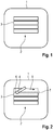
- a component 1 is shown on which a schematic printing pattern 2 is arranged.
- the print pattern 2 has individual substructures in the form of print strips 3, which are arranged close to one another. Clearances are arranged between the print strips 3, which are intended to clarify that the print strips 3 are not printed flush with one another during printing, but rather are printed at small distances from one another. Usually the attempt is made to choose the viscosity of the varnish so that the varnish runs or flows a little at the edges of the printing strips, thereby closing the free spaces.
- FIG 2 is an embodiment of the printing method according to the invention based on the in Figure 1 illustrated print pattern 2 illustrates.
- the individual print strips 3 are printed by means of a print head 4, which here has an exemplary rectangular shape.
- the print head 4 is moved from left to right (printing direction is indicated by arrow 5) and applies the print strips 3 in order from bottom to top.
- a treatment area 7 is shown between the uppermost and the print strip 3 arranged below it, which has at least the area between the two print strips 3 and also contains edge areas of the two print strips 3.
- the treatment area 7 can, for example, expediently be treated when printing the top printing strip 3 by means of an application head 6, which is arranged behind it with respect to the direction of movement 5 of the printing head 3 and is carried along during printing.
- the treatment in the treatment area 7 consequently takes place in pieces sliding from one side to the other side of the treatment area 7.
- the seam between the webs can be treated by means of the application head 6, so that the lacquer in Treatment area 7 can run better.
- the bottom three print strips are shown in FIG Figure 2 spaced apart, though the free spaces between these three printing strips 3 are closed or covered with lacquer, since corresponding treatment areas have already been irradiated with electromagnetic radiation and / or with ultrasound.
Landscapes
- Health & Medical Sciences (AREA)
- General Health & Medical Sciences (AREA)
- Toxicology (AREA)
- Physics & Mathematics (AREA)
- Engineering & Computer Science (AREA)
- Electromagnetism (AREA)
- Manufacturing & Machinery (AREA)
- Plasma & Fusion (AREA)
- Printing Methods (AREA)
- Application Of Or Painting With Fluid Materials (AREA)
- Ink Jet (AREA)
Abstract
Description
- Die vorliegende Erfindung betrifft ein Verfahren zum Bedrucken einer Oberfläche mit einem Druckmuster, insbesondere zum Bedrucken einer Fahrzeugkarosserie, sowie eine dazugehörige Druckvorrichtung, wobei beim Druckvorgang eine Glättung der Bereiche zwischen Teilstrukturen des Druckmusters vorgenommen wird.
- Es ist eine Technologie bekannt, die ähnlich wie ein konventioneller Drucker, gemäß welcher ein Muster auf eine Karosserie gedruckt werden kann, wobei es sich bei dem Muster etwa um Rallyestreifen handeln kann. Hierbei sei beispielhaft auf Druckschrift
DE 10 2014 221 103 A1 verwiesen, in der ein Verfahren zum mehrbahnigen Bedrucken von Automobilkarosserien offenbart ist. Bei Druckvorgängen dieser Art werden aufgrund der Form des Druckkopfes zu druckende flächige Muster in einzelnen Lackstreifen hinter- bzw. unter- oder übereinander gedruckt, ähnlich wie es bei einem gewöhnlichen Tintenstrahldrucker der Fall ist. Der Abstand zwischen den einzelnen Bahnen wird dabei derart gewählt, dass der Lack zwischen den Bahnen so verläuft, dass anschließend nach Aushärtung/Trocknung des Lacks eine geschlossene Farbfläche entsteht. Leider gestaltet sich das Auffinden optimaler Abstände zwischen den Streifen relativ schwierig, da das Fließverhalten des Lacks von vielen Parametern abhängig ist. Ein nicht optimal eingestellter Abstand zwischen den gedruckten Streifen kann dazu führen, dass die einzelnen Bahnen untereinander nicht geschlossen werden und/oder zu stark zerlaufen und es zur Bildung von Überlappbereichen kommt. Beide Effekte wirken sich negativ auf die Qualität des gedruckten Musters aus und sind daher zu vermeiden. - Ausgehend davon liegt der vorliegenden Erfindung die Aufgabe zu Grunde, ein Druckverfahren der eingangs genannten Art bereitzustellen, bei dem ein optimales Druckergebnis erreicht werden kann.
- Eine Lösung hierfür wird durch ein Verfahren zum Bedrucken einer Oberfläche und durch eine Vorrichtung zum Bedrucken einer Oberfläche gemäß den unabhängigen Patentansprüchen. Weitere Ausgestaltungen ergeben sich aus den abhängigen Patentansprüchen und der beiliegenden Beschreibung.
- Erfindungsgemäß weist das Verfahren zum Bedrucken einer Oberfläche mit einem Druckmuster Drucken einer ersten Teilstruktur des Druckmusters und Drucken einer zweiten Teilstruktur des Druckmusters in einem Abstand zu der ersten gedruckten Struktur auf. Ferner weist das Verfahren Behandeln mindestens eines Bereiches zwischen dem ersten Druckmuster und dem zweiten Druckmuster auf, indem dieser Bereich mit elektromagnetischen Wellen und/oder Schallwellen bestrahlt wird.
- Das erfindungsgemäße Verfahren kann insbesondere eingesetzt werden, um Lack auf Karosserieteile von Fahrzeugen, etwa Motorhauben oder Türen, anzubringen und so Druckmuster zu erzeugen. Das zu druckende Muster wird dabei in Teilstrukturen sequentiell gedruckt, wobei die Teilstrukturen eine nach der anderen in einem Abstand zueinander gedruckt werden. Der Abstand kann einige wenige Millimeter betragen. Ein bündiges Aneinanderreihen der Teilstrukturen wird nicht vorgenommen, da es dann meist zu den bereits erwähnten sichtbaren Überlagerungen des Lacks kommt und die Übergänge zwischen den Streifen somit nicht homogen sind. Bei dem erfindungsgemäßen Verfahren wird mindestens der Bereich zwischen der ersten Teilstruktur und der zweiten Teilstruktur nachbehandelt, indem er elektromagnetischer Strahlung und/oder Schallwellen ausgesetzt wird. Hierbei kann der behandelte Bereich zwischen der ersten Teilstruktur und der zweiten Teilstruktur selbstverständlich auch daran anliegende Randbereiche der beiden Teilstrukturen enthalten. Diese Tatsache spiegelt sich darin wieder, dass von der Behandlung mindestens des Bereiches zwischen den Teilstrukturen gesprochen wird. Mit anderen Worten ist bei dem Verfahren nicht beabsichtigt, ausschließlich den zwischen den gedruckten Teilstrukturen liegenden Bereich der Oberfläche zu behandeln, sondern auch die an diesen lackfreien Bereich anliegenden Randbereiche der Teilstrukturen. Aufgrund der üblicherweise kleinen räumlichen Abstände zwischen den gedruckten Teilstrukturen kann auch davon gesprochen werden, dass im Rahmen des erfindungsgemäßen Verfahrens die Naht zwischen einzelnen Druckbahnen behandelt wird.
- Das Bestrahlen des Behandlungsbereiches, also eines Bereiches der Oberfläche, in dem zwei Teilstrukturen nebeneinander angeordnet sind, mit elektromagnetischer Strahlung und/oder mit Schallwellen führt dazu, dass in diesem Bereich die Viskosität des Lacks erniedrigt wird. Diese Veränderung der Viskosität des Lacks ist bevorzugt lokal und temporär. Die Veränderung der Viskosität des Lacks geht mit einer Anpassung des Fließverhaltens des Lacks in dem Behandlungsbereich einher und kann insbesondere bewirken, dass der Lack entlang der Ränder von zwei durch eine Lücke getrennten Teilstrukturen zerläuft bzw. besser zerläuft und die Lücke so geschlossen wird. Anders ausgedrückt kann die Nachbehandlung mit elektromagnetischer und/oder akustischer Strahlung bewirken, dass zwei räumlich getrennte Teilstrukturen des Druckmusters entlang ihrer aneinander angrenzenden Ränder zusammengeführt werden. Das Fließverhalten des Lacks des gedruckten Musters kann dabei so gewählt werden, dass der Lack im Randbereich der Teilstrukturen ohne die Behandlung kaum oder gar nicht zerfließen würde und folglich die räumliche Trennung aufrecht erhalten werden würde. Insbesondere kann die Viskosität des verwendeten Lacks so gewählt werden, dass der Lack auf unebenen und/oder schräg gestellten Oberflächen gedruckt werden kann und dabei nicht von selbst zerfließt. Erst durch die lokale und temporäre Nachbehandlung mittels elektromagnetischen und/oder akustischen Wellen wird ein "Aufweichen" der Ränder der gedruckten Teilstrukturen herbeigeführt, was zum Schließen der Nahtstellen führt und ein gleichmäßiges Druckmuster ergibt.
- Ferner können im Rahmen des hier beschriebenen Verfahrens Lacke verwendet werden, welche keine Lösemittel aufweisen, um ein leichtes Zerfließen des Lacks herbeizuführen, nachdem auf die Oberfläche appliziert worden ist.
- Gemäß weiteren Ausführungsformen des Verfahrens kann das Behandeln des mindestens einen Bereiches zeitgleich mit dem Druckvorgang bzw. währenddessen erfolgen. Dabei kann der bestrahlte Bereich unmittelbar an den aktuellen Druckbereich angrenzen oder es kann zwischen den beiden Stellen ein Abstand vorliegen, welcher von zahlreichen Parametern wie Druckgeschwindigkeit, Lackdicke, Lacktrocknungszeit usw. abhängig sein und geeignet eingestellt werden kann. Unter dem aktuellen Druckbereich kann ein Bereich der Oberfläche verstanden werden, an dem zu dem betrachteten Zeitpunkt mittels eines Druckkopfes Lack auf die Oberfläche aufgebracht wird. Das Verfahren kann beispielsweise so eingerichtet sein, dass die durch eine entsprechende Strahlungsquelle bestrahlte Fläche innerhalb des Behandlungsbereiches dem aktuellen Druckbereich nachgeführt wird. So kann ein zwischen zwei Teilstrukturen liegender lackfreier Bereich samt angrenzenden Lackrändern behandelt werden, sobald die zweite Teilstruktur bzw. zweite Bahn von dem Druckkopf appliziert worden ist. Die bestrahlte Fläche innerhalb des Behandlungsbereiches kann dem aktuellen Druckbereich gleitend nachgeführt werden. Hierzu kann beispielsweise die entsprechende elektromagnetische und/oder akustische Strahlungsquelle einem Druckkopf eines Druckers nachgeführt werden.
- Gemäß weiteren Ausführungsformen des Verfahrens können die die elektromagnetischen Wellen im UV-Bereich und/oder IR-Bereich liegen. Die Bestrahlung mit elektromagnetischen Wellen kann allgemein zu einer thermischen bzw. optischen Anregung des Lacks führen. Die Bestrahlung mit Schallwellen kann als eine mechanische Anregung des Lacks im Behandlungsbereich aufgefasst werden und in etwa mit dem Effekt einer mikroskopischen Rüttelplatte veranschaulicht werden.
- Gemäß weiteren Ausführungsformen des Verfahrens kann der Lack, mittels welchem das Druckmuster gebildet wird, mindestens erste Farbpartikel bzw. und Additiv-Partikel aufweisen. Die Farbpartikel können für die Farbe des Lacks bestimmen. Die Wellenlänge der elektromagnetischen Wellen kann so gewählt werden, dass die Farbpartikel und/oder die Additiv-Partikel angeregt werden. Bei der Anregung mittels elektromagnetischer Strahlung kann es sich um eine optische bzw. eine thermische Anregung der Partikel und/oder der Additiv-Partikel handeln. Bei den Additiv-Partikeln kann es sich um Zusatzpartikel handeln, welche insbesondere für einen guten Energieeintrag in den Lack zu diesem hinzugefügt werden. Anders ausgedrückt können die Additiv-Partikel im Lack mittels auf diese abgestimmter elektromagnetischer Strahlung bestrahlt werden und so der Lack insgesamt erwärmt werden.
- Gemäß weiteren Ausführungsformen des Verfahrens kann es sich bei der ersten Teilstruktur und bei der zweiten Teilstruktur jeweils um einen Streifen handeln. Die Streifen können in Bahnen gedruckt werden, wobei eine Druckbahn einem Streifen entsprechen kann. Durch Aufdrucken einer Vielzahl von dicht aneinander angeordneten Streifen können ihre Nahtbereiche mittels der Nachbehandlung zusammengeführt werden und so beliebige größere Druckmuster erzeugt werden.
- In weiteren Ausführungsformen wird eine Vorrichtung zum Bedrucken einer Oberfläche mit einem Druckmuster bereitgestellt, wobei die Vorrichtung einen Druckkopf und einen Applikationskopf aufweist, welcher eine erste Abstrahlvorrichtung und eine zweite Abstrahlvorrichtung aufweist, wobei die erste Abstrahlvorrichtung zur Abstrahlung elektromagnetischer Wellen eingerichtet ist und die zweite Abstrahlvorrichtung zur Abstrahlung von Schallwellen eingerichtet ist. Die Vorrichtung kann zur Ausführung des erfindungsgemäßen Druckverfahrens verwendet werden.
- Gemäß weiteren Ausführungsformen der Druckvorrichtung kann der Applikationskopf an dem Druckkopf angeordnet sein. Der Applikationskopf kann beispielsweise derart seitlich am Druckkopf angeordnet sein, dass damit während eines stattfindenden Druckvorgangs ein dicht hinter dem aktuellen Druckbereich liegender Bereich bestrahlt wird. Ebenso kann der Applikationskopf in einem Abstand zu Druckkopf an diesen befestigt sein, so dass seine Bewegungsbahn an die Bewegungsbahn des Druckkopfes gekoppelt ist.
- Es versteht sich, dass die voranstehend genannten und die nachstehend noch zu erläuternden Merkmale nicht nur in der jeweils angegebenen Kombination, sondern auch in anderen Kombinationen oder in Alleinstellung verwendbar sind, ohne den Rahmen der vorliegenden Erfindung zu verlassen.
- Weitere Vorteile und Ausgestaltungen der Erfindung ergeben sich aus der Beschreibung und den beiliegenden Zeichnungen. Dabei zeigt
-
Figur 1 eine schematische Darstellung eins aus einzelnen Teilstrukturen aufgebautes Druckmuster. -
Figur 2 eine schematische Darstellung eins beispielhaften Druckvorgangs gemäß der Erfindung. - In
Figur 1 ist ein Bauteil 1 gezeigt, auf dem ein schematisches Druckmuster 2 angeordnet ist. Das Druckmuster 2 weist einzelne Teilstrukturen in Form von Druckstreifen 3 auf, welche dicht nebeneinander angeordnet sind. Zwischen den Druckstreifen 3 sind Freiräume angeordnet, welche verdeutlichen sollen, dass die Druckstreifen 3 beim Drucken nicht bündig aneinander, sondern in kleinen Abständen zueinander gedruckt werden. Üblicherweise wird versucht die Viskosität des Lacks so zu wählen, dass der Lack an den Rändern der Druckstreifen ein wenig zerläuft bzw. zerfließt und dadurch die Freiräume geschlossen werden. - In
Figur 2 ist ein Ausführungsbeispiel des erfindungsgemäßen Druckverfahrens auf Basis des inFigur 1 gezeigten Druckmusters 2 veranschaulicht. Die einzelnen Druckstreifen 3 werden mittels eines Druckkopfes 4 gedruckt, welcher hier eine beispielhaft rechteckige Form aufweist. Der Druckkopf 4 wird hierbei von links nach rechts bewegt (Druckrichtung ist mittels Pfeil 5 angedeutet) und appliziert die Druckstreifen 3 der Reihe nach von unten nach oben. Zwischen dem obersten und dem darunter angeordneten Druckstreifen 3 ist ein Behandlungsbereich 7 dargestellt, welcher mindestens den Bereich zwischen den beiden Druckstreifen 3 aufweist und auch Randbereiche der beiden Druckstreifen 3 enthält. Der Behandlungsbereich 7 kann beispielsweise zweckmäßigerweise beim Drucken des obersten Druckstreifens 3 behandelt werden mittels eines Applikationskopfes 6, welcher bezüglich der Bewegungsrichtung 5 des Druckkopfes 3 dahinter angeordnet ist und beim Drucken mitgeführt wird. Folglich erfolgt die Behandlung im Behandlungsbereich 7 stückweise gleitend von einer Seite zur anderen Seite des Behandlungsbereiches 7. Anders ausgedrückt kann, sobald eine zweite Lackbahn von dem Druckkopf 4 appliziert wird mittels des Applikationskopfes 6 die Naht zwischen den Bahnen behandelt werden, so dass der Lack im Behandlungsbereich 7 besser verlaufen kann. - Zur Veranschaulichung des Funktionsprinzips des erfindungsgemäßen Verfahrens sind die untersten drei Druckstreifen in
Figur 2 in einem Abstand zueinander angeordnet, obwohl die Freiräume zwischen diesen drei Druckstreifen 3 geschlossen bzw. mit Lack bedeckt sind, da entsprechenden Behandlungsbereiche bereits mit elektromagnetischer Strahlung und/oder mit Ultraschall bestrahlt worden sind.
Claims (8)
- Verfahren zum Bedrucken einer Oberfläche (1) mit einem Druckmuster (2), aufweisend:Drucken einer ersten Teilstruktur (3) des Druckmusters (2);Drucken einer zweiten Teilstruktur (3) des Druckmusters (2) in einem Abstand zu der ersten gedruckten Struktur;Behandeln mindestens eines Bereiches (7) zwischen dem ersten Druckmuster (3) und dem zweiten Druckmuster (3), indem dieser Bereich (7) mit elektromagnetischen Wellen und/oder Schallwellen bestrahlt wird.
- Verfahren gemäß Anspruch 1,
wobei durch die Bestrahlung des Bereiches (7) die Viskosität des Lacks in dem Bereich erniedrigt wird. - Verfahren gemäß Anspruch 1 oder 2,
wobei das Behandeln des mindestens einen Bereiches (3) zeitgleich mit dem Druckvorgang erfolgt. - Verfahren gemäß einem der Ansprüche 1 bis 3,
wobei die elektromagnetischen Wellen im UV-Bereich und/oder IR-Bereich liegen. - Verfahren gemäß einem der Ansprüche 1 bis 4,
wobei der Lack mindestens erste Farbpartikel und Additiv-Partikel aufweist; und wobei die Wellenlänge der elektromagnetischen Wellen geeignet ist, die Farbpartikel und/oder die Additiv-Partikel anzuregen. - Verfahren gemäß einem der Ansprüche 1 bis 5,
wobei es sich bei der ersten Teilstruktur und bei der zweiten Teilstruktur um einen Streifen (3) handelt. - Vorrichtung zum Bedrucken einer Oberfläche (1) mit einem Druckmuster (2), aufweisend:einen Druckkopf (4), undeinen Applikationskopf (6), welcher eine erste Abstrahlvorrichtung und eine zweite Abstrahlvorrichtung aufweist, wobei die erste Abstrahlvorrichtung zur Abstrahlung elektromagnetischer Wellen eingerichtet ist und die zweite Abstrahlvorrichtung zur Abstrahlung von Schallwellen eingerichtet ist.
- Vorrichtung gemäß Anspruch 8,
wobei der Applikationskopf (6) an dem Druckkopf (4) angeordnet ist.
Applications Claiming Priority (1)
| Application Number | Priority Date | Filing Date | Title |
|---|---|---|---|
| DE102019102247.9A DE102019102247A1 (de) | 2019-01-30 | 2019-01-30 | Verfahren zum Bedrucken einer Oberfläche mit einem Druckmuster und dazugehörige Druckvorrichtung |
Publications (2)
| Publication Number | Publication Date |
|---|---|
| EP3689619A1 true EP3689619A1 (de) | 2020-08-05 |
| EP3689619B1 EP3689619B1 (de) | 2024-03-27 |
Family
ID=68280671
Family Applications (1)
| Application Number | Title | Priority Date | Filing Date |
|---|---|---|---|
| EP19020576.5A Active EP3689619B1 (de) | 2019-01-30 | 2019-10-16 | Verfahren zum bedrucken einer oberfläche mit einem druckmuster und dazugehörige druckvorrichtung |
Country Status (4)
| Country | Link |
|---|---|
| US (1) | US11654706B2 (de) |
| EP (1) | EP3689619B1 (de) |
| CN (1) | CN111497479A (de) |
| DE (1) | DE102019102247A1 (de) |
Citations (3)
| Publication number | Priority date | Publication date | Assignee | Title |
|---|---|---|---|---|
| DE102007034877A1 (de) * | 2007-07-24 | 2009-01-29 | Schmid Rhyner Ag | Verfahren und Vorrichtung zum Auftrag von Kunststoffbeschichtungen |
| US20120321816A1 (en) * | 2011-06-14 | 2012-12-20 | Xerox Corporation | Systems and methods for leveling inks |
| DE102014221103A1 (de) | 2013-11-19 | 2014-12-18 | Heidelberger Druckmaschinen Ag | Verfahren zum Erzeugen eines Aufdrucks auf einem Objekt mit einer gekrümmten Oberfläche |
Family Cites Families (13)
| Publication number | Priority date | Publication date | Assignee | Title |
|---|---|---|---|---|
| WO2001011426A1 (en) * | 1999-05-27 | 2001-02-15 | Patterning Technologies Limited | Method of forming a masking pattern on a surface |
| FR2862563B1 (fr) * | 2003-11-24 | 2007-01-19 | Centre Nat Rech Scient | Robot d'impression numerique grand format en trois dimensions sur une surface fixe et procede d'impression mettant en oeuvre au moins un tel robot |
| DE102007034866A1 (de) | 2007-07-24 | 2009-01-29 | Evonik Degussa Gmbh | Ungesättigte Polyester |
| DE102008056237B4 (de) | 2007-12-07 | 2019-04-25 | Heidelberger Druckmaschinen Ag | Verfahren zum Trocknen von Druckfarbe und Druckfarbe |
| US8617667B2 (en) * | 2010-04-21 | 2013-12-31 | Xerox Corporation | Methods of leveling ink on substrates and apparatuses useful in printing |
| US8628177B2 (en) * | 2011-08-01 | 2014-01-14 | Xerox Corporation | Methods, apparatus, and systems for spreading radiation curable gel ink |
| US9150032B2 (en) * | 2011-08-31 | 2015-10-06 | Xerox Corporation | Methods, apparatus, and systems for controlling an initial line width of radiation curable gel ink |
| DE102012006371A1 (de) * | 2012-03-29 | 2012-07-05 | Heidelberger Druckmaschinen Aktiengesellschaft | Verfahren zum Bedrucken eines Objekts |
| JP2013256075A (ja) * | 2012-06-13 | 2013-12-26 | Fujifilm Corp | インクジェット記録装置及びその制御方法 |
| DE102012017538A1 (de) * | 2012-09-05 | 2014-03-06 | Heidelberger Druckmaschinen Ag | Verfahren zum Bebildern und/oder Lackieren der Oberfläche von Gegenständen |
| EP2848421B1 (de) * | 2013-09-12 | 2016-07-13 | Agfa Graphics Nv | Objekttintenstrahldruck auf großen quaderförmigen Körpern |
| US20160185128A1 (en) * | 2013-09-12 | 2016-06-30 | Agfa Graphics Nv | Large cuboid shaped object inkjet printing |
| JP6343944B2 (ja) * | 2014-01-30 | 2018-06-20 | セイコーエプソン株式会社 | インクジェット記録方法及び記録装置 |
-
2019
- 2019-01-30 DE DE102019102247.9A patent/DE102019102247A1/de active Pending
- 2019-10-16 EP EP19020576.5A patent/EP3689619B1/de active Active
-
2020
- 2020-01-22 CN CN202010075134.5A patent/CN111497479A/zh active Pending
- 2020-01-30 US US16/776,567 patent/US11654706B2/en active Active
Patent Citations (3)
| Publication number | Priority date | Publication date | Assignee | Title |
|---|---|---|---|---|
| DE102007034877A1 (de) * | 2007-07-24 | 2009-01-29 | Schmid Rhyner Ag | Verfahren und Vorrichtung zum Auftrag von Kunststoffbeschichtungen |
| US20120321816A1 (en) * | 2011-06-14 | 2012-12-20 | Xerox Corporation | Systems and methods for leveling inks |
| DE102014221103A1 (de) | 2013-11-19 | 2014-12-18 | Heidelberger Druckmaschinen Ag | Verfahren zum Erzeugen eines Aufdrucks auf einem Objekt mit einer gekrümmten Oberfläche |
Also Published As
| Publication number | Publication date |
|---|---|
| DE102019102247A1 (de) | 2020-07-30 |
| CN111497479A (zh) | 2020-08-07 |
| US20200238729A1 (en) | 2020-07-30 |
| US11654706B2 (en) | 2023-05-23 |
| EP3689619B1 (de) | 2024-03-27 |
Similar Documents
| Publication | Publication Date | Title |
|---|---|---|
| EP2707173B1 (de) | Verfahren und vorrichtung zum mechanischen entschichten beschichteter platinen unter verwendung einer presse und einem schabemesser | |
| AT512061B1 (de) | Tintenstrahldrucker und druckverfahren zum drucken eines bildes mit matten und glänzenden bildbereichen | |
| WO2007147376A1 (de) | Verfahren zur oberflächenstrukturierung eines pressbleches oder eines endlosbandes | |
| EP1990206B1 (de) | Verfahren und Vorrichtung zum Bedrucken eines Bauteils mit zwei zueinander geneigten Oberflächenbereichen mittels eines digitalen Druckverfahrens | |
| DE112013004555T5 (de) | Beschichtungsverfahren und Beschichtungsvorrichtung | |
| EP0845370A2 (de) | Verfahren zum Aufbringen von Markierungen, Beschriftungen und Strukturierungen auf die Oberfläche einer Ausweiskarte oder eineranderen Karte | |
| EP3689619B1 (de) | Verfahren zum bedrucken einer oberfläche mit einem druckmuster und dazugehörige druckvorrichtung | |
| DE102006012373B3 (de) | Breitschlitzdüse und Verfahren zum Auftragen von hochviskosem Material | |
| EP3547221B1 (de) | Verfahren zum bedrucken der oberfläche eines objekts | |
| DE4403243A1 (de) | Spritzvorrichtung zum Aufspritzen eines flüssigen Bindemittels | |
| DE102020210403A1 (de) | Fertigungseinrichtung und Verfahren zum additiven Fertigen von Bauteilen aus einem Pulvermaterial | |
| WO2018130536A1 (de) | Verfahren und vorrichtung zur herstellung von freilassungen in der beschichtung von transparenten bauteilen einer beleuchtungseinrichtung | |
| DE202021102425U1 (de) | Beschichter und Beschichteraufhängung | |
| AT521998B1 (de) | Verfahren zum Bedrucken von länglichen Profilleisten und Profilleisten | |
| EP1040916B1 (de) | Verfahren und Vorrichtung eines Druckwerkzeugs | |
| DE102017101719A1 (de) | Druckmaschine sowie verfahren zum bedrucken von werkstücken | |
| DE3704364C1 (de) | Verfahren zur Schnittkantenbehandlung von Zuschnitten aus bandlackiertem Material fuer Blechgehaeuseteile | |
| DE4410613C1 (de) | Vorrichtung zum Abtragen von Schichten einer Oberfläche mittels Laserstrahlung | |
| EP3928982B1 (de) | Verfahren zum gravieren einer intaglio-stichtiefdruckplatte, intaglio-stichtiefdruckplatte und druckverfahren | |
| DE102019211647A1 (de) | Verfahren zur Herstellung einer Lötverbindung durch Laserstrahllöten | |
| DE102022116426A1 (de) | Verfahren zur Bearbeitung einer Oberfläche eines Presswerkzeugs | |
| EP3254864B1 (de) | Merkmal und verfahren zu dessen herstellung | |
| DE202007017471U1 (de) | Strukturaggregat | |
| EP2189227B1 (de) | Verfahren und Vorrichtung zum Bestrahlen eines Körpers mit elektromagnetischer Strahlung | |
| EP3090874A1 (de) | Verfahren zum falzen eines lackierten, bahn- oder bogenförmigen bedruckstoffes |
Legal Events
| Date | Code | Title | Description |
|---|---|---|---|
| PUAI | Public reference made under article 153(3) epc to a published international application that has entered the european phase |
Free format text: ORIGINAL CODE: 0009012 |
|
| STAA | Information on the status of an ep patent application or granted ep patent |
Free format text: STATUS: THE APPLICATION HAS BEEN PUBLISHED |
|
| AK | Designated contracting states |
Kind code of ref document: A1 Designated state(s): AL AT BE BG CH CY CZ DE DK EE ES FI FR GB GR HR HU IE IS IT LI LT LU LV MC MK MT NL NO PL PT RO RS SE SI SK SM TR |
|
| AX | Request for extension of the european patent |
Extension state: BA ME |
|
| STAA | Information on the status of an ep patent application or granted ep patent |
Free format text: STATUS: REQUEST FOR EXAMINATION WAS MADE |
|
| 17P | Request for examination filed |
Effective date: 20210205 |
|
| RBV | Designated contracting states (corrected) |
Designated state(s): AL AT BE BG CH CY CZ DE DK EE ES FI FR GB GR HR HU IE IS IT LI LT LU LV MC MK MT NL NO PL PT RO RS SE SI SK SM TR |
|
| STAA | Information on the status of an ep patent application or granted ep patent |
Free format text: STATUS: EXAMINATION IS IN PROGRESS |
|
| 17Q | First examination report despatched |
Effective date: 20220617 |
|
| P01 | Opt-out of the competence of the unified patent court (upc) registered |
Effective date: 20230526 |
|
| REG | Reference to a national code |
Ref country code: DE Ref legal event code: R079 Free format text: PREVIOUS MAIN CLASS: B41J0003407000 Ipc: B05D0001400000 Ref country code: DE Ref legal event code: R079 Ref document number: 502019010874 Country of ref document: DE Free format text: PREVIOUS MAIN CLASS: B41J0003407000 Ipc: B05D0001400000 |
|
| GRAP | Despatch of communication of intention to grant a patent |
Free format text: ORIGINAL CODE: EPIDOSNIGR1 |
|
| STAA | Information on the status of an ep patent application or granted ep patent |
Free format text: STATUS: GRANT OF PATENT IS INTENDED |
|
| RIC1 | Information provided on ipc code assigned before grant |
Ipc: B41J 11/00 20060101ALI20231115BHEP Ipc: B41J 3/407 20060101ALI20231115BHEP Ipc: B41M 7/00 20060101ALI20231115BHEP Ipc: B41M 3/00 20060101ALI20231115BHEP Ipc: B05D 3/06 20060101ALI20231115BHEP Ipc: B05D 1/40 20060101AFI20231115BHEP |
|
| INTG | Intention to grant announced |
Effective date: 20231205 |
|
| GRAS | Grant fee paid |
Free format text: ORIGINAL CODE: EPIDOSNIGR3 |
|
| GRAA | (expected) grant |
Free format text: ORIGINAL CODE: 0009210 |
|
| STAA | Information on the status of an ep patent application or granted ep patent |
Free format text: STATUS: THE PATENT HAS BEEN GRANTED |
|
| AK | Designated contracting states |
Kind code of ref document: B1 Designated state(s): AL AT BE BG CH CY CZ DE DK EE ES FI FR GB GR HR HU IE IS IT LI LT LU LV MC MK MT NL NO PL PT RO RS SE SI SK SM TR |
|
| REG | Reference to a national code |
Ref country code: GB Ref legal event code: FG4D Free format text: NOT ENGLISH |
|
| REG | Reference to a national code |
Ref country code: CH Ref legal event code: EP |
|
| REG | Reference to a national code |
Ref country code: DE Ref legal event code: R096 Ref document number: 502019010874 Country of ref document: DE |
|
| REG | Reference to a national code |
Ref country code: IE Ref legal event code: FG4D Free format text: LANGUAGE OF EP DOCUMENT: GERMAN |
|
| REG | Reference to a national code |
Ref country code: SK Ref legal event code: T3 Ref document number: E 43955 Country of ref document: SK |
|
| PG25 | Lapsed in a contracting state [announced via postgrant information from national office to epo] |
Ref country code: LT Free format text: LAPSE BECAUSE OF FAILURE TO SUBMIT A TRANSLATION OF THE DESCRIPTION OR TO PAY THE FEE WITHIN THE PRESCRIBED TIME-LIMIT Effective date: 20240327 |
|
| REG | Reference to a national code |
Ref country code: LT Ref legal event code: MG9D |
|
| PG25 | Lapsed in a contracting state [announced via postgrant information from national office to epo] |
Ref country code: GR Free format text: LAPSE BECAUSE OF FAILURE TO SUBMIT A TRANSLATION OF THE DESCRIPTION OR TO PAY THE FEE WITHIN THE PRESCRIBED TIME-LIMIT Effective date: 20240628 |
|
| PG25 | Lapsed in a contracting state [announced via postgrant information from national office to epo] |
Ref country code: HR Free format text: LAPSE BECAUSE OF FAILURE TO SUBMIT A TRANSLATION OF THE DESCRIPTION OR TO PAY THE FEE WITHIN THE PRESCRIBED TIME-LIMIT Effective date: 20240327 Ref country code: RS Free format text: LAPSE BECAUSE OF FAILURE TO SUBMIT A TRANSLATION OF THE DESCRIPTION OR TO PAY THE FEE WITHIN THE PRESCRIBED TIME-LIMIT Effective date: 20240627 |
|
| PG25 | Lapsed in a contracting state [announced via postgrant information from national office to epo] |
Ref country code: RS Free format text: LAPSE BECAUSE OF FAILURE TO SUBMIT A TRANSLATION OF THE DESCRIPTION OR TO PAY THE FEE WITHIN THE PRESCRIBED TIME-LIMIT Effective date: 20240627 Ref country code: NO Free format text: LAPSE BECAUSE OF FAILURE TO SUBMIT A TRANSLATION OF THE DESCRIPTION OR TO PAY THE FEE WITHIN THE PRESCRIBED TIME-LIMIT Effective date: 20240627 Ref country code: LT Free format text: LAPSE BECAUSE OF FAILURE TO SUBMIT A TRANSLATION OF THE DESCRIPTION OR TO PAY THE FEE WITHIN THE PRESCRIBED TIME-LIMIT Effective date: 20240327 Ref country code: HR Free format text: LAPSE BECAUSE OF FAILURE TO SUBMIT A TRANSLATION OF THE DESCRIPTION OR TO PAY THE FEE WITHIN THE PRESCRIBED TIME-LIMIT Effective date: 20240327 Ref country code: GR Free format text: LAPSE BECAUSE OF FAILURE TO SUBMIT A TRANSLATION OF THE DESCRIPTION OR TO PAY THE FEE WITHIN THE PRESCRIBED TIME-LIMIT Effective date: 20240628 Ref country code: FI Free format text: LAPSE BECAUSE OF FAILURE TO SUBMIT A TRANSLATION OF THE DESCRIPTION OR TO PAY THE FEE WITHIN THE PRESCRIBED TIME-LIMIT Effective date: 20240327 Ref country code: BG Free format text: LAPSE BECAUSE OF FAILURE TO SUBMIT A TRANSLATION OF THE DESCRIPTION OR TO PAY THE FEE WITHIN THE PRESCRIBED TIME-LIMIT Effective date: 20240327 |
|
| REG | Reference to a national code |
Ref country code: NL Ref legal event code: MP Effective date: 20240327 |
|
| PG25 | Lapsed in a contracting state [announced via postgrant information from national office to epo] |
Ref country code: SE Free format text: LAPSE BECAUSE OF FAILURE TO SUBMIT A TRANSLATION OF THE DESCRIPTION OR TO PAY THE FEE WITHIN THE PRESCRIBED TIME-LIMIT Effective date: 20240327 Ref country code: LV Free format text: LAPSE BECAUSE OF FAILURE TO SUBMIT A TRANSLATION OF THE DESCRIPTION OR TO PAY THE FEE WITHIN THE PRESCRIBED TIME-LIMIT Effective date: 20240327 |
|
| PG25 | Lapsed in a contracting state [announced via postgrant information from national office to epo] |
Ref country code: NL Free format text: LAPSE BECAUSE OF FAILURE TO SUBMIT A TRANSLATION OF THE DESCRIPTION OR TO PAY THE FEE WITHIN THE PRESCRIBED TIME-LIMIT Effective date: 20240327 |
|
| PG25 | Lapsed in a contracting state [announced via postgrant information from national office to epo] |
Ref country code: NL Free format text: LAPSE BECAUSE OF FAILURE TO SUBMIT A TRANSLATION OF THE DESCRIPTION OR TO PAY THE FEE WITHIN THE PRESCRIBED TIME-LIMIT Effective date: 20240327 |
|
| PG25 | Lapsed in a contracting state [announced via postgrant information from national office to epo] |
Ref country code: IS Free format text: LAPSE BECAUSE OF FAILURE TO SUBMIT A TRANSLATION OF THE DESCRIPTION OR TO PAY THE FEE WITHIN THE PRESCRIBED TIME-LIMIT Effective date: 20240727 |
|
| PG25 | Lapsed in a contracting state [announced via postgrant information from national office to epo] |
Ref country code: PT Free format text: LAPSE BECAUSE OF FAILURE TO SUBMIT A TRANSLATION OF THE DESCRIPTION OR TO PAY THE FEE WITHIN THE PRESCRIBED TIME-LIMIT Effective date: 20240729 Ref country code: SM Free format text: LAPSE BECAUSE OF FAILURE TO SUBMIT A TRANSLATION OF THE DESCRIPTION OR TO PAY THE FEE WITHIN THE PRESCRIBED TIME-LIMIT Effective date: 20240327 |
|
| PG25 | Lapsed in a contracting state [announced via postgrant information from national office to epo] |
Ref country code: ES Free format text: LAPSE BECAUSE OF FAILURE TO SUBMIT A TRANSLATION OF THE DESCRIPTION OR TO PAY THE FEE WITHIN THE PRESCRIBED TIME-LIMIT Effective date: 20240327 |
|
| PG25 | Lapsed in a contracting state [announced via postgrant information from national office to epo] |
Ref country code: EE Free format text: LAPSE BECAUSE OF FAILURE TO SUBMIT A TRANSLATION OF THE DESCRIPTION OR TO PAY THE FEE WITHIN THE PRESCRIBED TIME-LIMIT Effective date: 20240327 Ref country code: CZ Free format text: LAPSE BECAUSE OF FAILURE TO SUBMIT A TRANSLATION OF THE DESCRIPTION OR TO PAY THE FEE WITHIN THE PRESCRIBED TIME-LIMIT Effective date: 20240327 |
|
| PG25 | Lapsed in a contracting state [announced via postgrant information from national office to epo] |
Ref country code: PL Free format text: LAPSE BECAUSE OF FAILURE TO SUBMIT A TRANSLATION OF THE DESCRIPTION OR TO PAY THE FEE WITHIN THE PRESCRIBED TIME-LIMIT Effective date: 20240327 |
|
| PG25 | Lapsed in a contracting state [announced via postgrant information from national office to epo] |
Ref country code: SM Free format text: LAPSE BECAUSE OF FAILURE TO SUBMIT A TRANSLATION OF THE DESCRIPTION OR TO PAY THE FEE WITHIN THE PRESCRIBED TIME-LIMIT Effective date: 20240327 Ref country code: RO Free format text: LAPSE BECAUSE OF FAILURE TO SUBMIT A TRANSLATION OF THE DESCRIPTION OR TO PAY THE FEE WITHIN THE PRESCRIBED TIME-LIMIT Effective date: 20240327 Ref country code: PT Free format text: LAPSE BECAUSE OF FAILURE TO SUBMIT A TRANSLATION OF THE DESCRIPTION OR TO PAY THE FEE WITHIN THE PRESCRIBED TIME-LIMIT Effective date: 20240729 Ref country code: PL Free format text: LAPSE BECAUSE OF FAILURE TO SUBMIT A TRANSLATION OF THE DESCRIPTION OR TO PAY THE FEE WITHIN THE PRESCRIBED TIME-LIMIT Effective date: 20240327 Ref country code: IS Free format text: LAPSE BECAUSE OF FAILURE TO SUBMIT A TRANSLATION OF THE DESCRIPTION OR TO PAY THE FEE WITHIN THE PRESCRIBED TIME-LIMIT Effective date: 20240727 Ref country code: ES Free format text: LAPSE BECAUSE OF FAILURE TO SUBMIT A TRANSLATION OF THE DESCRIPTION OR TO PAY THE FEE WITHIN THE PRESCRIBED TIME-LIMIT Effective date: 20240327 Ref country code: EE Free format text: LAPSE BECAUSE OF FAILURE TO SUBMIT A TRANSLATION OF THE DESCRIPTION OR TO PAY THE FEE WITHIN THE PRESCRIBED TIME-LIMIT Effective date: 20240327 Ref country code: CZ Free format text: LAPSE BECAUSE OF FAILURE TO SUBMIT A TRANSLATION OF THE DESCRIPTION OR TO PAY THE FEE WITHIN THE PRESCRIBED TIME-LIMIT Effective date: 20240327 |
|
| PG25 | Lapsed in a contracting state [announced via postgrant information from national office to epo] |
Ref country code: IT Free format text: LAPSE BECAUSE OF FAILURE TO SUBMIT A TRANSLATION OF THE DESCRIPTION OR TO PAY THE FEE WITHIN THE PRESCRIBED TIME-LIMIT Effective date: 20240327 |
|
| PG25 | Lapsed in a contracting state [announced via postgrant information from national office to epo] |
Ref country code: IT Free format text: LAPSE BECAUSE OF FAILURE TO SUBMIT A TRANSLATION OF THE DESCRIPTION OR TO PAY THE FEE WITHIN THE PRESCRIBED TIME-LIMIT Effective date: 20240327 |
|
| REG | Reference to a national code |
Ref country code: DE Ref legal event code: R097 Ref document number: 502019010874 Country of ref document: DE |
|
| PG25 | Lapsed in a contracting state [announced via postgrant information from national office to epo] |
Ref country code: DK Free format text: LAPSE BECAUSE OF FAILURE TO SUBMIT A TRANSLATION OF THE DESCRIPTION OR TO PAY THE FEE WITHIN THE PRESCRIBED TIME-LIMIT Effective date: 20240327 |
|
| PG25 | Lapsed in a contracting state [announced via postgrant information from national office to epo] |
Ref country code: DK Free format text: LAPSE BECAUSE OF FAILURE TO SUBMIT A TRANSLATION OF THE DESCRIPTION OR TO PAY THE FEE WITHIN THE PRESCRIBED TIME-LIMIT Effective date: 20240327 |
|
| PLBE | No opposition filed within time limit |
Free format text: ORIGINAL CODE: 0009261 |
|
| STAA | Information on the status of an ep patent application or granted ep patent |
Free format text: STATUS: NO OPPOSITION FILED WITHIN TIME LIMIT |
|
| 26N | No opposition filed |
Effective date: 20250103 |
|
| PG25 | Lapsed in a contracting state [announced via postgrant information from national office to epo] |
Ref country code: SI Free format text: LAPSE BECAUSE OF FAILURE TO SUBMIT A TRANSLATION OF THE DESCRIPTION OR TO PAY THE FEE WITHIN THE PRESCRIBED TIME-LIMIT Effective date: 20240327 |
|
| REG | Reference to a national code |
Ref country code: CH Ref legal event code: PL |
|
| PG25 | Lapsed in a contracting state [announced via postgrant information from national office to epo] |
Ref country code: MC Free format text: LAPSE BECAUSE OF FAILURE TO SUBMIT A TRANSLATION OF THE DESCRIPTION OR TO PAY THE FEE WITHIN THE PRESCRIBED TIME-LIMIT Effective date: 20240327 |
|
| PG25 | Lapsed in a contracting state [announced via postgrant information from national office to epo] |
Ref country code: BE Free format text: LAPSE BECAUSE OF NON-PAYMENT OF DUE FEES Effective date: 20241031 Ref country code: LU Free format text: LAPSE BECAUSE OF NON-PAYMENT OF DUE FEES Effective date: 20241016 |
|
| PG25 | Lapsed in a contracting state [announced via postgrant information from national office to epo] |
Ref country code: CH Free format text: LAPSE BECAUSE OF NON-PAYMENT OF DUE FEES Effective date: 20241031 |
|
| REG | Reference to a national code |
Ref country code: BE Ref legal event code: MM Effective date: 20241031 |
|
| PG25 | Lapsed in a contracting state [announced via postgrant information from national office to epo] |
Ref country code: IE Free format text: LAPSE BECAUSE OF NON-PAYMENT OF DUE FEES Effective date: 20241016 |
|
| REG | Reference to a national code |
Ref country code: AT Ref legal event code: MM01 Ref document number: 1669417 Country of ref document: AT Kind code of ref document: T Effective date: 20241016 |
|
| PGFP | Annual fee paid to national office [announced via postgrant information from national office to epo] |
Ref country code: DE Payment date: 20251029 Year of fee payment: 7 |
|
| PGFP | Annual fee paid to national office [announced via postgrant information from national office to epo] |
Ref country code: GB Payment date: 20251022 Year of fee payment: 7 |
|
| PG25 | Lapsed in a contracting state [announced via postgrant information from national office to epo] |
Ref country code: AT Free format text: LAPSE BECAUSE OF NON-PAYMENT OF DUE FEES Effective date: 20241016 |
|
| PGFP | Annual fee paid to national office [announced via postgrant information from national office to epo] |
Ref country code: FR Payment date: 20251030 Year of fee payment: 7 |
|
| PGFP | Annual fee paid to national office [announced via postgrant information from national office to epo] |
Ref country code: SK Payment date: 20251008 Year of fee payment: 7 |
|
| PG25 | Lapsed in a contracting state [announced via postgrant information from national office to epo] |
Ref country code: CY Free format text: LAPSE BECAUSE OF FAILURE TO SUBMIT A TRANSLATION OF THE DESCRIPTION OR TO PAY THE FEE WITHIN THE PRESCRIBED TIME-LIMIT; INVALID AB INITIO Effective date: 20191016 |
|
| PG25 | Lapsed in a contracting state [announced via postgrant information from national office to epo] |
Ref country code: HU Free format text: LAPSE BECAUSE OF FAILURE TO SUBMIT A TRANSLATION OF THE DESCRIPTION OR TO PAY THE FEE WITHIN THE PRESCRIBED TIME-LIMIT; INVALID AB INITIO Effective date: 20191016 |
|
| PG25 | Lapsed in a contracting state [announced via postgrant information from national office to epo] |
Ref country code: TR Free format text: LAPSE BECAUSE OF FAILURE TO SUBMIT A TRANSLATION OF THE DESCRIPTION OR TO PAY THE FEE WITHIN THE PRESCRIBED TIME-LIMIT Effective date: 20240327 |