EP3689528A2 - System und verfahren zum laserbohren von geformten kühllöchern - Google Patents
System und verfahren zum laserbohren von geformten kühllöchern Download PDFInfo
- Publication number
- EP3689528A2 EP3689528A2 EP19216207.1A EP19216207A EP3689528A2 EP 3689528 A2 EP3689528 A2 EP 3689528A2 EP 19216207 A EP19216207 A EP 19216207A EP 3689528 A2 EP3689528 A2 EP 3689528A2
- Authority
- EP
- European Patent Office
- Prior art keywords
- laser
- component
- focal plane
- laser source
- spherical lens
- Prior art date
- Legal status (The legal status is an assumption and is not a legal conclusion. Google has not performed a legal analysis and makes no representation as to the accuracy of the status listed.)
- Granted
Links
Images


Classifications
-
- B—PERFORMING OPERATIONS; TRANSPORTING
- B23—MACHINE TOOLS; METAL-WORKING NOT OTHERWISE PROVIDED FOR
- B23K—SOLDERING OR UNSOLDERING; WELDING; CLADDING OR PLATING BY SOLDERING OR WELDING; CUTTING BY APPLYING HEAT LOCALLY, e.g. FLAME CUTTING; WORKING BY LASER BEAM
- B23K26/00—Working by laser beam, e.g. welding, cutting or boring
- B23K26/02—Positioning or observing the workpiece, e.g. with respect to the point of impact; Aligning, aiming or focusing the laser beam
- B23K26/06—Shaping the laser beam, e.g. by masks or multi-focusing
- B23K26/064—Shaping the laser beam, e.g. by masks or multi-focusing by means of optical elements, e.g. lenses, mirrors or prisms
- B23K26/0648—Shaping the laser beam, e.g. by masks or multi-focusing by means of optical elements, e.g. lenses, mirrors or prisms comprising lenses
-
- B—PERFORMING OPERATIONS; TRANSPORTING
- B23—MACHINE TOOLS; METAL-WORKING NOT OTHERWISE PROVIDED FOR
- B23K—SOLDERING OR UNSOLDERING; WELDING; CLADDING OR PLATING BY SOLDERING OR WELDING; CUTTING BY APPLYING HEAT LOCALLY, e.g. FLAME CUTTING; WORKING BY LASER BEAM
- B23K26/00—Working by laser beam, e.g. welding, cutting or boring
- B23K26/36—Removing material
- B23K26/38—Removing material by boring or cutting
- B23K26/382—Removing material by boring or cutting by boring
- B23K26/384—Removing material by boring or cutting by boring of specially shaped holes
-
- B—PERFORMING OPERATIONS; TRANSPORTING
- B23—MACHINE TOOLS; METAL-WORKING NOT OTHERWISE PROVIDED FOR
- B23K—SOLDERING OR UNSOLDERING; WELDING; CLADDING OR PLATING BY SOLDERING OR WELDING; CUTTING BY APPLYING HEAT LOCALLY, e.g. FLAME CUTTING; WORKING BY LASER BEAM
- B23K26/00—Working by laser beam, e.g. welding, cutting or boring
- B23K26/02—Positioning or observing the workpiece, e.g. with respect to the point of impact; Aligning, aiming or focusing the laser beam
- B23K26/06—Shaping the laser beam, e.g. by masks or multi-focusing
- B23K26/073—Shaping the laser spot
-
- B—PERFORMING OPERATIONS; TRANSPORTING
- B23—MACHINE TOOLS; METAL-WORKING NOT OTHERWISE PROVIDED FOR
- B23K—SOLDERING OR UNSOLDERING; WELDING; CLADDING OR PLATING BY SOLDERING OR WELDING; CUTTING BY APPLYING HEAT LOCALLY, e.g. FLAME CUTTING; WORKING BY LASER BEAM
- B23K26/00—Working by laser beam, e.g. welding, cutting or boring
- B23K26/36—Removing material
- B23K26/38—Removing material by boring or cutting
- B23K26/382—Removing material by boring or cutting by boring
- B23K26/389—Removing material by boring or cutting by boring of fluid openings, e.g. nozzles, jets
-
- B—PERFORMING OPERATIONS; TRANSPORTING
- B23—MACHINE TOOLS; METAL-WORKING NOT OTHERWISE PROVIDED FOR
- B23P—METAL-WORKING NOT OTHERWISE PROVIDED FOR; COMBINED OPERATIONS; UNIVERSAL MACHINE TOOLS
- B23P15/00—Making specific metal objects by operations not covered by a single other subclass or a group in this subclass
- B23P15/02—Making specific metal objects by operations not covered by a single other subclass or a group in this subclass turbine or like blades from one piece
-
- F—MECHANICAL ENGINEERING; LIGHTING; HEATING; WEAPONS; BLASTING
- F01—MACHINES OR ENGINES IN GENERAL; ENGINE PLANTS IN GENERAL; STEAM ENGINES
- F01D—NON-POSITIVE DISPLACEMENT MACHINES OR ENGINES, e.g. STEAM TURBINES
- F01D5/00—Blades; Blade-carrying members; Heating, heat-insulating, cooling or antivibration means on the blades or the members
- F01D5/12—Blades
- F01D5/14—Form or construction
- F01D5/18—Hollow blades, i.e. blades with cooling or heating channels or cavities; Heating, heat-insulating or cooling means on blades
- F01D5/186—Film cooling
-
- F—MECHANICAL ENGINEERING; LIGHTING; HEATING; WEAPONS; BLASTING
- F01—MACHINES OR ENGINES IN GENERAL; ENGINE PLANTS IN GENERAL; STEAM ENGINES
- F01D—NON-POSITIVE DISPLACEMENT MACHINES OR ENGINES, e.g. STEAM TURBINES
- F01D5/00—Blades; Blade-carrying members; Heating, heat-insulating, cooling or antivibration means on the blades or the members
- F01D5/12—Blades
- F01D5/14—Form or construction
- F01D5/18—Hollow blades, i.e. blades with cooling or heating channels or cavities; Heating, heat-insulating or cooling means on blades
- F01D5/187—Convection cooling
-
- G—PHYSICS
- G02—OPTICS
- G02B—OPTICAL ELEMENTS, SYSTEMS OR APPARATUS
- G02B27/00—Optical systems or apparatus not provided for by any of the groups G02B1/00 - G02B26/00, G02B30/00
- G02B27/09—Beam shaping, e.g. changing the cross-sectional area, not otherwise provided for
- G02B27/0927—Systems for changing the beam intensity distribution, e.g. Gaussian to top-hat
-
- G—PHYSICS
- G02—OPTICS
- G02B—OPTICAL ELEMENTS, SYSTEMS OR APPARATUS
- G02B6/00—Light guides; Structural details of arrangements comprising light guides and other optical elements, e.g. couplings
- G02B6/04—Light guides; Structural details of arrangements comprising light guides and other optical elements, e.g. couplings formed by bundles of fibres
-
- G—PHYSICS
- G02—OPTICS
- G02B—OPTICAL ELEMENTS, SYSTEMS OR APPARATUS
- G02B6/00—Light guides; Structural details of arrangements comprising light guides and other optical elements, e.g. couplings
- G02B6/10—Light guides; Structural details of arrangements comprising light guides and other optical elements, e.g. couplings of the optical waveguide type
-
- B—PERFORMING OPERATIONS; TRANSPORTING
- B23—MACHINE TOOLS; METAL-WORKING NOT OTHERWISE PROVIDED FOR
- B23K—SOLDERING OR UNSOLDERING; WELDING; CLADDING OR PLATING BY SOLDERING OR WELDING; CUTTING BY APPLYING HEAT LOCALLY, e.g. FLAME CUTTING; WORKING BY LASER BEAM
- B23K2101/00—Articles made by soldering, welding or cutting
- B23K2101/001—Turbines
-
- B—PERFORMING OPERATIONS; TRANSPORTING
- B23—MACHINE TOOLS; METAL-WORKING NOT OTHERWISE PROVIDED FOR
- B23P—METAL-WORKING NOT OTHERWISE PROVIDED FOR; COMBINED OPERATIONS; UNIVERSAL MACHINE TOOLS
- B23P2700/00—Indexing scheme relating to the articles being treated, e.g. manufactured, repaired, assembled, connected or other operations covered in the subgroups
- B23P2700/06—Cooling passages of turbine components, e.g. unblocking or preventing blocking of cooling passages of turbine components
-
- F—MECHANICAL ENGINEERING; LIGHTING; HEATING; WEAPONS; BLASTING
- F05—INDEXING SCHEMES RELATING TO ENGINES OR PUMPS IN VARIOUS SUBCLASSES OF CLASSES F01-F04
- F05D—INDEXING SCHEME FOR ASPECTS RELATING TO NON-POSITIVE-DISPLACEMENT MACHINES OR ENGINES, GAS-TURBINES OR JET-PROPULSION PLANTS
- F05D2230/00—Manufacture
- F05D2230/10—Manufacture by removing material
- F05D2230/13—Manufacture by removing material using lasers
-
- F—MECHANICAL ENGINEERING; LIGHTING; HEATING; WEAPONS; BLASTING
- F05—INDEXING SCHEMES RELATING TO ENGINES OR PUMPS IN VARIOUS SUBCLASSES OF CLASSES F01-F04
- F05D—INDEXING SCHEME FOR ASPECTS RELATING TO NON-POSITIVE-DISPLACEMENT MACHINES OR ENGINES, GAS-TURBINES OR JET-PROPULSION PLANTS
- F05D2250/00—Geometry
- F05D2250/10—Two-dimensional
- F05D2250/18—Two-dimensional patterned
- F05D2250/185—Two-dimensional patterned serpentine-like
-
- F—MECHANICAL ENGINEERING; LIGHTING; HEATING; WEAPONS; BLASTING
- F05—INDEXING SCHEMES RELATING TO ENGINES OR PUMPS IN VARIOUS SUBCLASSES OF CLASSES F01-F04
- F05D—INDEXING SCHEME FOR ASPECTS RELATING TO NON-POSITIVE-DISPLACEMENT MACHINES OR ENGINES, GAS-TURBINES OR JET-PROPULSION PLANTS
- F05D2260/00—Function
- F05D2260/20—Heat transfer, e.g. cooling
- F05D2260/202—Heat transfer, e.g. cooling by film cooling
-
- F—MECHANICAL ENGINEERING; LIGHTING; HEATING; WEAPONS; BLASTING
- F05—INDEXING SCHEMES RELATING TO ENGINES OR PUMPS IN VARIOUS SUBCLASSES OF CLASSES F01-F04
- F05D—INDEXING SCHEME FOR ASPECTS RELATING TO NON-POSITIVE-DISPLACEMENT MACHINES OR ENGINES, GAS-TURBINES OR JET-PROPULSION PLANTS
- F05D2260/00—Function
- F05D2260/20—Heat transfer, e.g. cooling
- F05D2260/221—Improvement of heat transfer
- F05D2260/2214—Improvement of heat transfer by increasing the heat transfer surface
- F05D2260/22141—Improvement of heat transfer by increasing the heat transfer surface using fins or ribs
-
- G—PHYSICS
- G02—OPTICS
- G02B—OPTICAL ELEMENTS, SYSTEMS OR APPARATUS
- G02B3/00—Simple or compound lenses
- G02B2003/0093—Simple or compound lenses characterised by the shape
-
- G—PHYSICS
- G02—OPTICS
- G02B—OPTICAL ELEMENTS, SYSTEMS OR APPARATUS
- G02B3/00—Simple or compound lenses
Definitions
- the present disclosure relates to a method for laser drilling, and more particularly to a method for laser hole drilling of shaped cooling holes for gas turbine engine components.
- Gas turbine engines typically include a compressor section to pressurize airflow, a combustor section to burn a hydrocarbon fuel in the presence of the pressurized air, and a turbine section to extract energy from the resultant combustion gases.
- Gas path components such as turbine blades, often include cooling that may be accomplished by external film cooling, internal air impingement, and forced convection either separately or in combination.
- forced convection cooling compressor bleed air flows through internal chambers to continuously remove thermal energy. The compressor bleed air enters the internal chambers through one or more inlets to the internal chambers, which then discharge though various hole exits.
- the cooling air holes are drilled in pre-determined patterns and are contoured to ensure adequate cooling of the airfoil.
- the cooling air holes duct cooling air from passages on the interior of the airfoil through the hot walls to the exterior.
- the cooling air provides transpiration cooling as the air passes through the wall and, after the air is discharged from the airfoil, provides film cooling with a film of air on the exterior.
- the film of cooling air provides a barrier between the airfoil and the hot, working medium gasses.
- One process to drill the holes utilizes a laser beam that burns through the wall of the airfoil to form a hole that provides a satisfactory conduit for cooling air.
- Laser hole drilling is performed by focusing a laser (typically 1026 nm) onto the gas turbine component.
- Shaped cooling holes typically include a meter hole with a portion that may not penetrate through the wall. Shaped cooling holes are produced through the use of machining processes such as EDM, which is of a significantly higher cost than laser hole drilling. This issue may drive component design to avoid shaped cooling holes.
- a laser hole drilling system includes a laser source that generates a laser beam along an optical axis; a spherical lens along the optical axis downstream of the laser source; and a control system in communication with the spherical lens and the laser source, the control system operable to position the spherical lens with respect to the laser source to produce a light distribution based on polar coordinates of a real portion of the Fourier Transform of a laser plane at the laser source to generate an asymmetric teardrop shaped energy distribution at a focal plane.
- a further aspect of the present disclosure includes, wherein the spherical lens is located coaxial with respect to the optical axis.
- a further aspect of the present disclosure includes, wherein the focal plane is located at a surface of a turbine component.
- a component for a gas turbine engine includes a surface with a laser drilled asymmetric teardrop shaped cooling hole.
- a further aspect of the present disclosure includes, wherein the surface is a wall of a turbine blade.
- a laser hole drilling system includes a laser matrix of fiber waveguide lasers arranged in an array; and a control system in communication with the laser matrix, the control system operable to control a laser distribution and intensity between nodes in the array produce a light distribution based on polar coordinates of a real portion of the Fourier Transform of a laser plane at the laser source to generate an asymmetric teardrop shaped energy distribution at a focal plane.
- a further aspect of the present disclosure includes, wherein the focal plane is located at a surface of a turbine component.
- a further aspect of the present disclosure includes, wherein the surface is a wall of a turbine blade.
- a method for laser drilling an asymmetric teardrop shaped cooling hole in a component for a gas turbine engine includes locating a component with respect to a focal plane of a laser; producing a light distribution based on polar coordinates of a real portion of a Fourier Transform of a laser plane at the laser source to generate an asymmetric teardrop shaped energy distribution at the focal plane; and drilling an asymmetric teardrop shaped cooling hole in the component at the focal plane.
- a further aspect of the present disclosure includes, wherein the focal plane is located at a surface of a turbine component.
- FIG. 1 schematically illustrates an example blade 100 for a gas turbine engine such as a turbine blade.
- the blade 100 generally includes a root 102, a platform 104 and an airfoil 106 (also shown in FIG. 2 and 3 ).
- the platform 104 separates a gas path side inclusive of the airfoil 106 and a non-gas path side inclusive of the root 102.
- the platform 104 generally separates the root 102 and the airfoil 106 to define an inner boundary of a gas path.
- the airfoil 106 defines a blade chord between a leading edge 120, which may include various forward and/or aft sweep configurations, and a trailing edge 122.
- a first wall 130 may be convex to define a suction side, and a second wall 132 may be concave to define a pressure side are joined at the leading edge and at the axially spaced trailing edge.
- a blade tip 140 extends between the walls 130, 132 opposite the platform 104. It should be appreciated that the tip 140 may include a recessed portion.
- each blade 100 may be formed by casting to include an array of internal passageways 108 (also shown schematically in FIG. 2 ) that communicate with a multiple of holes 110 (illustrated schematically) that direct cooling air over an outer surface of the airfoil 106, here exemplified by the leading edge 120 (also shown schematically in FIG. 3 ).
- a blade 100 with cooling holes will be described and illustrated in detail as one example, other components including, but not limited to, vanes, turbine shrouds, end walls and other components will also benefit herefrom.
- the array of internal passageways 108 includes a feed passage 112 that communicates airflow into a multiple of leading edge chambers 114 within the blade 100.
- the feed passage 112 generally receives cooling flow through at least one inlet 116 within a base 118 of the root 102.
- the multiple of leading edge chambers 114 of a leading edge cavity 122 generally receives cooling flow from the feed passage 112 through respective crossover passages 150.
- the multiple of holes 110 provide for cooling air egress to an external surface of the blade 100. It should be appreciated that although particular features are delineated within certain general areas, the features may be otherwise arranged or intermingled and still not depart from the disclosure herein. It should also be appreciated that various feed passage architectures; cavities and internal feature arrangements, e.g., pedestals, chevrons, pin fins, chevrons, etc., for the array of internal passageways 108 may also be provided.
- the multiple of holes 110 may include a multiple of shaped cooling holes 170 that communicate the cooling airflow from the internal cooling circuit through the wall of the blade 100 to provide external film cooling which allow exit of the internal cooling flow used in forced convection cooling.
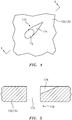
- the shaped cooling holes 170 include a metering hole 172 and a trailing portion 174 that may not penetrate and/or may be angled with regard the walls 130, 132 of the blade 100 to form an asymmetric teardrop shape ( FIG. 4 and 5 ).
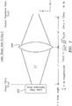
- a laser hole drilling system 200 includes a laser source 202, a spherical lens 204 along an optical axis L, and a control system 206 therefore.
- the spherical lens 204 may be positioned by an articulatable support 208 in response to the control system 206 ( FIG. 7 ).
- the control system 206 includes a processor 210, a memory 212, and an interface 214.
- the processor 210 may be any type of known microprocessor having desired performance characteristics.
- the memory 212 may be any computer readable medium which stores data and control algorithms such as the logic 300 as described herein.
- the interface 214 facilitates communication with other components such as the laser source 202 and the articulatable support 208.
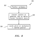
- the functions of the logic 300 are disclosed in terms of functional block diagrams in FIG. 8 , and it should be appreciated that these functions may be enacted in either dedicated hardware circuitry or programmed software routines capable of execution in a microprocessor-based electronics control embodiment.
- an example method 300 for laser drilling the shaped cooling hole 170 With reference to FIG. 8 , an example method 300 for laser drilling the shaped cooling hole 170.
- the steps of the method 300 are schematically disclosed in terms of functional block diagrams as a flowchart of steps. It should be appreciated that alternative of addition steps may be provided without departing from the teaching herein.
- a component such as the blade 100
- the light distribution will be the Fourier Transform of the input of the light to the spherical lens 204.
- the spherical lens 204 which is in a coaxial arrangement with the laser source 202, will produce a light distribution in polar coordinates of the real portion of the Fourier Transform at the Fourier Transform plane. That is, the laser plane at the laser source 202 is converted by the position of the spherical lens 204 to define the Fourier Transform plane (304) and thus the shaped cooling hole 170.
- Parallel rays that are off the optical axis L will map to a non-polar symmetric energy distribution. That is, the laser beam propagates through the spherical lens 204 thereby introducing an asymmetric teardrop shaped energy distribution at a focal plane to drill the shaped cooling hole 170 at the desired position (306). The asymmetric teardrop shaped energy distribution thereby drills the teardrop shape cooling hole 170 at the focal plane.
- the focal plane By controlling the focal plane the breakthrough of the respective wall 130, 132 forming the metering hole 172 while the trailing portion 174 does not breakthrough the wall 130, 132.
- the laser source 202 may be a laser matrix of fiber waveguide lasers in an array format controlled by the control system 206.
- the laser matrix is controlled in laser distribution and intensity between nodes (pixels) in the array.
- the output of the array can be de-magnified and imaged directly onto the work piece to form the shaped cooling hole 170. That is the direct computer control of the laser matrix controls the shape of the hole to be drilled. If greater laser intensity is required, the array may be controlled to produce a pattern corresponding to the inverse Fourier Transform of the desired shape.
- the array energy is then directly focused (not imaged), onto the work piece. The resulting energy distribution will correspond directly to the shape of the hole to be produced.
- the method for laser drilling the shaped cooling hole is inexpensive and readily incorporated into existing and future components.
Landscapes
- Physics & Mathematics (AREA)
- Engineering & Computer Science (AREA)
- Optics & Photonics (AREA)
- Mechanical Engineering (AREA)
- Plasma & Fusion (AREA)
- General Physics & Mathematics (AREA)
- General Engineering & Computer Science (AREA)
- Turbine Rotor Nozzle Sealing (AREA)
- Laser Beam Processing (AREA)
Applications Claiming Priority (1)
| Application Number | Priority Date | Filing Date | Title |
|---|---|---|---|
| US16/220,415 US12042881B2 (en) | 2018-12-14 | 2018-12-14 | System and method for laser drilling of shaped cooling holes |
Publications (3)
| Publication Number | Publication Date |
|---|---|
| EP3689528A2 true EP3689528A2 (de) | 2020-08-05 |
| EP3689528A3 EP3689528A3 (de) | 2020-11-11 |
| EP3689528B1 EP3689528B1 (de) | 2024-01-24 |
Family
ID=68917382
Family Applications (1)
| Application Number | Title | Priority Date | Filing Date |
|---|---|---|---|
| EP19216207.1A Active EP3689528B1 (de) | 2018-12-14 | 2019-12-13 | System und verfahren zum laserbohren von geformten kühllöchern |
Country Status (2)
| Country | Link |
|---|---|
| US (2) | US12042881B2 (de) |
| EP (1) | EP3689528B1 (de) |
Families Citing this family (1)
| Publication number | Priority date | Publication date | Assignee | Title |
|---|---|---|---|---|
| CN115657294B (zh) * | 2022-12-26 | 2023-04-11 | 中国航天三江集团有限公司 | 螺旋可调式高功率激光液冷截止光阑 |
Family Cites Families (22)
| Publication number | Priority date | Publication date | Assignee | Title |
|---|---|---|---|---|
| JP2004335575A (ja) | 2003-05-01 | 2004-11-25 | Canon Inc | 露光装置 |
| JP4929761B2 (ja) | 2006-03-02 | 2012-05-09 | リコープリンティングシステムズ株式会社 | 光走査装置及びこれを使用した画像形成装置 |
| JP2009072789A (ja) | 2007-09-18 | 2009-04-09 | Hamamatsu Photonics Kk | レーザ加工装置 |
| WO2010053911A2 (en) | 2008-11-04 | 2010-05-14 | Massachusetts Institute Of Technology | External-cavity one-dimensional multi-wavelength beam combining of two-dimensional laser elements |
| US8119949B2 (en) * | 2008-11-26 | 2012-02-21 | Honeywell International Inc. | Laser cutting shaped holes by trepanning on the fly |
| US8525073B2 (en) | 2010-01-27 | 2013-09-03 | United Technologies Corporation | Depth and breakthrough detection for laser machining |
| WO2011109753A1 (en) | 2010-03-05 | 2011-09-09 | TeraDiode, Inc. | Wavelength beam combining based pump / pulsed lasers |
| US8461480B2 (en) | 2010-11-30 | 2013-06-11 | Electro Scientific Industries, Inc. | Orthogonal integrated cleaving device |
| US9093822B1 (en) | 2010-12-20 | 2015-07-28 | TeraDiode, Inc. | Multi-band co-bore-sighted scalable output power laser system |
| CN103340017B (zh) | 2011-01-28 | 2015-04-22 | 首尔半导体株式会社 | Led驱动电路封装 |
| US9250390B2 (en) * | 2011-12-09 | 2016-02-02 | Lumentum Operations Llc | Varying beam parameter product of a laser beam |
| US20150367451A1 (en) | 2014-06-19 | 2015-12-24 | Ipg Photonics Corporation | High power fiber laser effusion hole drilling apparatus and method of using same |
| US9598979B2 (en) * | 2012-02-15 | 2017-03-21 | United Technologies Corporation | Manufacturing methods for multi-lobed cooling holes |
| US9823480B2 (en) | 2012-02-22 | 2017-11-21 | TeraDiode, Inc. | Wavelength beam combining laser systems with micro-optics |
| DE102013212665B4 (de) * | 2013-06-28 | 2015-06-25 | Laser Zentrum Hannover E.V. | Verfahren zum Laserbohren oder Laserschneiden eines Werkstücks |
| JP5833093B2 (ja) | 2013-12-26 | 2015-12-16 | シャープ株式会社 | 加工装置 |
| US20160214208A1 (en) * | 2015-01-22 | 2016-07-28 | General Electric Company | System and method for forming passages in an airfoil |
| US10668654B2 (en) * | 2015-01-30 | 2020-06-02 | Raytheon Technologies Corporation | Method for disposing a blocking material |
| JP2018009550A (ja) | 2016-07-15 | 2018-01-18 | 川崎重工業株式会社 | ガスタービンエンジンの冷却構造およびその製造方法 |
| US10310246B2 (en) * | 2016-09-28 | 2019-06-04 | SCREEN Holdings Co., Ltd. | Converter, illuminator, and light sheet fluorescence microscope |
| CN110167755B (zh) | 2017-01-05 | 2022-04-08 | Ipg光子公司 | 增材激光加工系统和方法 |
| US20180238173A1 (en) | 2017-02-22 | 2018-08-23 | General Electric Company | Method of manufacturing turbine airfoil and tip component thereof |
-
2018
- 2018-12-14 US US16/220,415 patent/US12042881B2/en active Active
-
2019
- 2019-12-13 EP EP19216207.1A patent/EP3689528B1/de active Active
-
2024
- 2024-06-21 US US18/750,822 patent/US20260048454A1/en active Pending
Also Published As
| Publication number | Publication date |
|---|---|
| US20260048454A1 (en) | 2026-02-19 |
| EP3689528A3 (de) | 2020-11-11 |
| US20200189041A1 (en) | 2020-06-18 |
| US12042881B2 (en) | 2024-07-23 |
| EP3689528B1 (de) | 2024-01-24 |
Similar Documents
| Publication | Publication Date | Title |
|---|---|---|
| US7056093B2 (en) | Gas turbine aerofoil | |
| US11021969B2 (en) | Turbine blade | |
| US11448076B2 (en) | Engine component with cooling hole | |
| US4672727A (en) | Method of fabricating film cooling slot in a hollow airfoil | |
| US6099251A (en) | Coolable airfoil for a gas turbine engine | |
| US20050135920A1 (en) | Cooled turbine vane platform | |
| US10519780B2 (en) | Dual-walled components for a gas turbine engine | |
| US10370978B2 (en) | Turbine blade | |
| JP2004003459A (ja) | ガスタービンエンジンのノズル組立体を冷却する方法及び装置 | |
| US20260048454A1 (en) | System and method for laser drilling of shaped cooling holes | |
| US11480058B2 (en) | Engine component with set of cooling holes | |
| US20190186272A1 (en) | Engine component with cooling hole | |
| US11053809B2 (en) | Turbine engine airfoil | |
| US20210310362A1 (en) | Cooled airfoil and method of making | |
| CN106884683A (zh) | 利用薄膜冷却的发动机构件 | |
| US10563518B2 (en) | Gas turbine engine trailing edge ejection holes | |
| WO2017074404A1 (en) | Turbine airfoil with offset impingement cooling at leading edge | |
| EP3683001B1 (de) | System und verfahren zum laserbohren von geformten kühllöchern | |
| CN108213628A (zh) | 用于硬钎焊的发动机构件的方法及设备 | |
| US10668654B2 (en) | Method for disposing a blocking material | |
| JP2025093861A (ja) | 先端冷却通路を有するエアフォイルを修理する方法 | |
| EP3159481A1 (de) | Prallkühlung für endspitzen einer gasturbinenschaufel | |
| Naik et al. | GT36 turbine aero-thermal development and validation | |
| Searle et al. | Novel Additively-Manufactured and Internally-Cooled Airfoils for Increasing Small Industrial Gas Turbine Efficiency | |
| US12497896B2 (en) | Airfoil assembly with platform film holes |
Legal Events
| Date | Code | Title | Description |
|---|---|---|---|
| PUAI | Public reference made under article 153(3) epc to a published international application that has entered the european phase |
Free format text: ORIGINAL CODE: 0009012 |
|
| STAA | Information on the status of an ep patent application or granted ep patent |
Free format text: STATUS: THE APPLICATION HAS BEEN PUBLISHED |
|
| AK | Designated contracting states |
Kind code of ref document: A2 Designated state(s): AL AT BE BG CH CY CZ DE DK EE ES FI FR GB GR HR HU IE IS IT LI LT LU LV MC MK MT NL NO PL PT RO RS SE SI SK SM TR |
|
| AX | Request for extension of the european patent |
Extension state: BA ME |
|
| PUAL | Search report despatched |
Free format text: ORIGINAL CODE: 0009013 |
|
| AK | Designated contracting states |
Kind code of ref document: A3 Designated state(s): AL AT BE BG CH CY CZ DE DK EE ES FI FR GB GR HR HU IE IS IT LI LT LU LV MC MK MT NL NO PL PT RO RS SE SI SK SM TR |
|
| AX | Request for extension of the european patent |
Extension state: BA ME |
|
| RIC1 | Information provided on ipc code assigned before grant |
Ipc: B23K 101/00 20060101ALN20201002BHEP Ipc: B23K 26/384 20140101ALI20201002BHEP Ipc: B23K 26/06 20140101AFI20201002BHEP Ipc: B23K 26/073 20060101ALI20201002BHEP Ipc: B23K 26/382 20140101ALI20201002BHEP |
|
| RAP1 | Party data changed (applicant data changed or rights of an application transferred) |
Owner name: RAYTHEON TECHNOLOGIES CORPORATION |
|
| STAA | Information on the status of an ep patent application or granted ep patent |
Free format text: STATUS: REQUEST FOR EXAMINATION WAS MADE |
|
| 17P | Request for examination filed |
Effective date: 20210511 |
|
| RBV | Designated contracting states (corrected) |
Designated state(s): AL AT BE BG CH CY CZ DE DK EE ES FI FR GB GR HR HU IE IS IT LI LT LU LV MC MK MT NL NO PL PT RO RS SE SI SK SM TR |
|
| RIC1 | Information provided on ipc code assigned before grant |
Ipc: B23K 101/00 20060101ALN20220902BHEP Ipc: B23K 26/382 20140101ALI20220902BHEP Ipc: B23K 26/384 20140101ALI20220902BHEP Ipc: B23K 26/073 20060101ALI20220902BHEP Ipc: B23K 26/06 20140101AFI20220902BHEP |
|
| RIC1 | Information provided on ipc code assigned before grant |
Ipc: B23K 101/00 20060101ALN20221005BHEP Ipc: B23K 26/382 20140101ALI20221005BHEP Ipc: B23K 26/384 20140101ALI20221005BHEP Ipc: B23K 26/073 20060101ALI20221005BHEP Ipc: B23K 26/06 20140101AFI20221005BHEP |
|
| STAA | Information on the status of an ep patent application or granted ep patent |
Free format text: STATUS: EXAMINATION IS IN PROGRESS |
|
| 17Q | First examination report despatched |
Effective date: 20221207 |
|
| GRAP | Despatch of communication of intention to grant a patent |
Free format text: ORIGINAL CODE: EPIDOSNIGR1 |
|
| STAA | Information on the status of an ep patent application or granted ep patent |
Free format text: STATUS: GRANT OF PATENT IS INTENDED |
|
| RIC1 | Information provided on ipc code assigned before grant |
Ipc: B23K 101/00 20060101ALN20230621BHEP Ipc: B23K 26/382 20140101ALI20230621BHEP Ipc: B23K 26/384 20140101ALI20230621BHEP Ipc: B23K 26/073 20060101ALI20230621BHEP Ipc: B23K 26/06 20140101AFI20230621BHEP |
|
| RIC1 | Information provided on ipc code assigned before grant |
Ipc: B23K 101/00 20060101ALN20230704BHEP Ipc: B23K 26/382 20140101ALI20230704BHEP Ipc: B23K 26/384 20140101ALI20230704BHEP Ipc: B23K 26/073 20060101ALI20230704BHEP Ipc: B23K 26/06 20140101AFI20230704BHEP |
|
| INTG | Intention to grant announced |
Effective date: 20230718 |
|
| RIN1 | Information on inventor provided before grant (corrected) |
Inventor name: WINTER, MICHAEL |
|
| RAP3 | Party data changed (applicant data changed or rights of an application transferred) |
Owner name: RTX CORPORATION |
|
| GRAS | Grant fee paid |
Free format text: ORIGINAL CODE: EPIDOSNIGR3 |
|
| GRAA | (expected) grant |
Free format text: ORIGINAL CODE: 0009210 |
|
| STAA | Information on the status of an ep patent application or granted ep patent |
Free format text: STATUS: THE PATENT HAS BEEN GRANTED |
|
| AK | Designated contracting states |
Kind code of ref document: B1 Designated state(s): AL AT BE BG CH CY CZ DE DK EE ES FI FR GB GR HR HU IE IS IT LI LT LU LV MC MK MT NL NO PL PT RO RS SE SI SK SM TR |
|
| REG | Reference to a national code |
Ref country code: GB Ref legal event code: FG4D |
|
| REG | Reference to a national code |
Ref country code: CH Ref legal event code: EP |
|
| REG | Reference to a national code |
Ref country code: IE Ref legal event code: FG4D |
|
| REG | Reference to a national code |
Ref country code: DE Ref legal event code: R096 Ref document number: 602019045519 Country of ref document: DE |
|
| REG | Reference to a national code |
Ref country code: LT Ref legal event code: MG9D |
|
| REG | Reference to a national code |
Ref country code: NL Ref legal event code: MP Effective date: 20240124 |
|
| PG25 | Lapsed in a contracting state [announced via postgrant information from national office to epo] |
Ref country code: NL Free format text: LAPSE BECAUSE OF FAILURE TO SUBMIT A TRANSLATION OF THE DESCRIPTION OR TO PAY THE FEE WITHIN THE PRESCRIBED TIME-LIMIT Effective date: 20240124 |
|
| PG25 | Lapsed in a contracting state [announced via postgrant information from national office to epo] |
Ref country code: NL Free format text: LAPSE BECAUSE OF FAILURE TO SUBMIT A TRANSLATION OF THE DESCRIPTION OR TO PAY THE FEE WITHIN THE PRESCRIBED TIME-LIMIT Effective date: 20240124 |
|
| PG25 | Lapsed in a contracting state [announced via postgrant information from national office to epo] |
Ref country code: IS Free format text: LAPSE BECAUSE OF FAILURE TO SUBMIT A TRANSLATION OF THE DESCRIPTION OR TO PAY THE FEE WITHIN THE PRESCRIBED TIME-LIMIT Effective date: 20240524 |
|
| PG25 | Lapsed in a contracting state [announced via postgrant information from national office to epo] |
Ref country code: LT Free format text: LAPSE BECAUSE OF FAILURE TO SUBMIT A TRANSLATION OF THE DESCRIPTION OR TO PAY THE FEE WITHIN THE PRESCRIBED TIME-LIMIT Effective date: 20240124 |
|
| PG25 | Lapsed in a contracting state [announced via postgrant information from national office to epo] |
Ref country code: GR Free format text: LAPSE BECAUSE OF FAILURE TO SUBMIT A TRANSLATION OF THE DESCRIPTION OR TO PAY THE FEE WITHIN THE PRESCRIBED TIME-LIMIT Effective date: 20240425 |
|
| REG | Reference to a national code |
Ref country code: AT Ref legal event code: MK05 Ref document number: 1651804 Country of ref document: AT Kind code of ref document: T Effective date: 20240124 |
|
| PG25 | Lapsed in a contracting state [announced via postgrant information from national office to epo] |
Ref country code: HR Free format text: LAPSE BECAUSE OF FAILURE TO SUBMIT A TRANSLATION OF THE DESCRIPTION OR TO PAY THE FEE WITHIN THE PRESCRIBED TIME-LIMIT Effective date: 20240124 Ref country code: RS Free format text: LAPSE BECAUSE OF FAILURE TO SUBMIT A TRANSLATION OF THE DESCRIPTION OR TO PAY THE FEE WITHIN THE PRESCRIBED TIME-LIMIT Effective date: 20240424 |
|
| PG25 | Lapsed in a contracting state [announced via postgrant information from national office to epo] |
Ref country code: ES Free format text: LAPSE BECAUSE OF FAILURE TO SUBMIT A TRANSLATION OF THE DESCRIPTION OR TO PAY THE FEE WITHIN THE PRESCRIBED TIME-LIMIT Effective date: 20240124 |
|
| PG25 | Lapsed in a contracting state [announced via postgrant information from national office to epo] |
Ref country code: AT Free format text: LAPSE BECAUSE OF FAILURE TO SUBMIT A TRANSLATION OF THE DESCRIPTION OR TO PAY THE FEE WITHIN THE PRESCRIBED TIME-LIMIT Effective date: 20240124 |
|
| PG25 | Lapsed in a contracting state [announced via postgrant information from national office to epo] |
Ref country code: RS Free format text: LAPSE BECAUSE OF FAILURE TO SUBMIT A TRANSLATION OF THE DESCRIPTION OR TO PAY THE FEE WITHIN THE PRESCRIBED TIME-LIMIT Effective date: 20240424 Ref country code: NO Free format text: LAPSE BECAUSE OF FAILURE TO SUBMIT A TRANSLATION OF THE DESCRIPTION OR TO PAY THE FEE WITHIN THE PRESCRIBED TIME-LIMIT Effective date: 20240424 Ref country code: LT Free format text: LAPSE BECAUSE OF FAILURE TO SUBMIT A TRANSLATION OF THE DESCRIPTION OR TO PAY THE FEE WITHIN THE PRESCRIBED TIME-LIMIT Effective date: 20240124 Ref country code: IS Free format text: LAPSE BECAUSE OF FAILURE TO SUBMIT A TRANSLATION OF THE DESCRIPTION OR TO PAY THE FEE WITHIN THE PRESCRIBED TIME-LIMIT Effective date: 20240524 Ref country code: HR Free format text: LAPSE BECAUSE OF FAILURE TO SUBMIT A TRANSLATION OF THE DESCRIPTION OR TO PAY THE FEE WITHIN THE PRESCRIBED TIME-LIMIT Effective date: 20240124 Ref country code: GR Free format text: LAPSE BECAUSE OF FAILURE TO SUBMIT A TRANSLATION OF THE DESCRIPTION OR TO PAY THE FEE WITHIN THE PRESCRIBED TIME-LIMIT Effective date: 20240425 Ref country code: FI Free format text: LAPSE BECAUSE OF FAILURE TO SUBMIT A TRANSLATION OF THE DESCRIPTION OR TO PAY THE FEE WITHIN THE PRESCRIBED TIME-LIMIT Effective date: 20240124 Ref country code: ES Free format text: LAPSE BECAUSE OF FAILURE TO SUBMIT A TRANSLATION OF THE DESCRIPTION OR TO PAY THE FEE WITHIN THE PRESCRIBED TIME-LIMIT Effective date: 20240124 Ref country code: BG Free format text: LAPSE BECAUSE OF FAILURE TO SUBMIT A TRANSLATION OF THE DESCRIPTION OR TO PAY THE FEE WITHIN THE PRESCRIBED TIME-LIMIT Effective date: 20240124 Ref country code: AT Free format text: LAPSE BECAUSE OF FAILURE TO SUBMIT A TRANSLATION OF THE DESCRIPTION OR TO PAY THE FEE WITHIN THE PRESCRIBED TIME-LIMIT Effective date: 20240124 |
|
| PG25 | Lapsed in a contracting state [announced via postgrant information from national office to epo] |
Ref country code: PL Free format text: LAPSE BECAUSE OF FAILURE TO SUBMIT A TRANSLATION OF THE DESCRIPTION OR TO PAY THE FEE WITHIN THE PRESCRIBED TIME-LIMIT Effective date: 20240124 Ref country code: PT Free format text: LAPSE BECAUSE OF FAILURE TO SUBMIT A TRANSLATION OF THE DESCRIPTION OR TO PAY THE FEE WITHIN THE PRESCRIBED TIME-LIMIT Effective date: 20240524 |
|
| PG25 | Lapsed in a contracting state [announced via postgrant information from national office to epo] |
Ref country code: SE Free format text: LAPSE BECAUSE OF FAILURE TO SUBMIT A TRANSLATION OF THE DESCRIPTION OR TO PAY THE FEE WITHIN THE PRESCRIBED TIME-LIMIT Effective date: 20240124 Ref country code: PT Free format text: LAPSE BECAUSE OF FAILURE TO SUBMIT A TRANSLATION OF THE DESCRIPTION OR TO PAY THE FEE WITHIN THE PRESCRIBED TIME-LIMIT Effective date: 20240524 Ref country code: PL Free format text: LAPSE BECAUSE OF FAILURE TO SUBMIT A TRANSLATION OF THE DESCRIPTION OR TO PAY THE FEE WITHIN THE PRESCRIBED TIME-LIMIT Effective date: 20240124 Ref country code: LV Free format text: LAPSE BECAUSE OF FAILURE TO SUBMIT A TRANSLATION OF THE DESCRIPTION OR TO PAY THE FEE WITHIN THE PRESCRIBED TIME-LIMIT Effective date: 20240124 |
|
| PG25 | Lapsed in a contracting state [announced via postgrant information from national office to epo] |
Ref country code: DK Free format text: LAPSE BECAUSE OF FAILURE TO SUBMIT A TRANSLATION OF THE DESCRIPTION OR TO PAY THE FEE WITHIN THE PRESCRIBED TIME-LIMIT Effective date: 20240124 |
|
| PG25 | Lapsed in a contracting state [announced via postgrant information from national office to epo] |
Ref country code: SM Free format text: LAPSE BECAUSE OF FAILURE TO SUBMIT A TRANSLATION OF THE DESCRIPTION OR TO PAY THE FEE WITHIN THE PRESCRIBED TIME-LIMIT Effective date: 20240124 |
|
| PG25 | Lapsed in a contracting state [announced via postgrant information from national office to epo] |
Ref country code: EE Free format text: LAPSE BECAUSE OF FAILURE TO SUBMIT A TRANSLATION OF THE DESCRIPTION OR TO PAY THE FEE WITHIN THE PRESCRIBED TIME-LIMIT Effective date: 20240124 Ref country code: CZ Free format text: LAPSE BECAUSE OF FAILURE TO SUBMIT A TRANSLATION OF THE DESCRIPTION OR TO PAY THE FEE WITHIN THE PRESCRIBED TIME-LIMIT Effective date: 20240124 |
|
| REG | Reference to a national code |
Ref country code: DE Ref legal event code: R097 Ref document number: 602019045519 Country of ref document: DE |
|
| PG25 | Lapsed in a contracting state [announced via postgrant information from national office to epo] |
Ref country code: SK Free format text: LAPSE BECAUSE OF FAILURE TO SUBMIT A TRANSLATION OF THE DESCRIPTION OR TO PAY THE FEE WITHIN THE PRESCRIBED TIME-LIMIT Effective date: 20240124 |
|
| PG25 | Lapsed in a contracting state [announced via postgrant information from national office to epo] |
Ref country code: SM Free format text: LAPSE BECAUSE OF FAILURE TO SUBMIT A TRANSLATION OF THE DESCRIPTION OR TO PAY THE FEE WITHIN THE PRESCRIBED TIME-LIMIT Effective date: 20240124 Ref country code: SK Free format text: LAPSE BECAUSE OF FAILURE TO SUBMIT A TRANSLATION OF THE DESCRIPTION OR TO PAY THE FEE WITHIN THE PRESCRIBED TIME-LIMIT Effective date: 20240124 Ref country code: RO Free format text: LAPSE BECAUSE OF FAILURE TO SUBMIT A TRANSLATION OF THE DESCRIPTION OR TO PAY THE FEE WITHIN THE PRESCRIBED TIME-LIMIT Effective date: 20240124 Ref country code: EE Free format text: LAPSE BECAUSE OF FAILURE TO SUBMIT A TRANSLATION OF THE DESCRIPTION OR TO PAY THE FEE WITHIN THE PRESCRIBED TIME-LIMIT Effective date: 20240124 Ref country code: DK Free format text: LAPSE BECAUSE OF FAILURE TO SUBMIT A TRANSLATION OF THE DESCRIPTION OR TO PAY THE FEE WITHIN THE PRESCRIBED TIME-LIMIT Effective date: 20240124 Ref country code: CZ Free format text: LAPSE BECAUSE OF FAILURE TO SUBMIT A TRANSLATION OF THE DESCRIPTION OR TO PAY THE FEE WITHIN THE PRESCRIBED TIME-LIMIT Effective date: 20240124 |
|
| PLBE | No opposition filed within time limit |
Free format text: ORIGINAL CODE: 0009261 |
|
| STAA | Information on the status of an ep patent application or granted ep patent |
Free format text: STATUS: NO OPPOSITION FILED WITHIN TIME LIMIT |
|
| PG25 | Lapsed in a contracting state [announced via postgrant information from national office to epo] |
Ref country code: IT Free format text: LAPSE BECAUSE OF FAILURE TO SUBMIT A TRANSLATION OF THE DESCRIPTION OR TO PAY THE FEE WITHIN THE PRESCRIBED TIME-LIMIT Effective date: 20240124 |
|
| PG25 | Lapsed in a contracting state [announced via postgrant information from national office to epo] |
Ref country code: IT Free format text: LAPSE BECAUSE OF FAILURE TO SUBMIT A TRANSLATION OF THE DESCRIPTION OR TO PAY THE FEE WITHIN THE PRESCRIBED TIME-LIMIT Effective date: 20240124 |
|
| 26N | No opposition filed |
Effective date: 20241025 |
|
| PG25 | Lapsed in a contracting state [announced via postgrant information from national office to epo] |
Ref country code: SI Free format text: LAPSE BECAUSE OF FAILURE TO SUBMIT A TRANSLATION OF THE DESCRIPTION OR TO PAY THE FEE WITHIN THE PRESCRIBED TIME-LIMIT Effective date: 20240124 |
|
| PG25 | Lapsed in a contracting state [announced via postgrant information from national office to epo] |
Ref country code: MC Free format text: LAPSE BECAUSE OF FAILURE TO SUBMIT A TRANSLATION OF THE DESCRIPTION OR TO PAY THE FEE WITHIN THE PRESCRIBED TIME-LIMIT Effective date: 20240124 |
|
| REG | Reference to a national code |
Ref country code: CH Ref legal event code: PL |
|
| PG25 | Lapsed in a contracting state [announced via postgrant information from national office to epo] |
Ref country code: LU Free format text: LAPSE BECAUSE OF NON-PAYMENT OF DUE FEES Effective date: 20241213 |
|
| REG | Reference to a national code |
Ref country code: BE Ref legal event code: MM Effective date: 20241231 |
|
| PG25 | Lapsed in a contracting state [announced via postgrant information from national office to epo] |
Ref country code: BE Free format text: LAPSE BECAUSE OF NON-PAYMENT OF DUE FEES Effective date: 20241231 |
|
| PG25 | Lapsed in a contracting state [announced via postgrant information from national office to epo] |
Ref country code: CH Free format text: LAPSE BECAUSE OF NON-PAYMENT OF DUE FEES Effective date: 20241231 |
|
| PG25 | Lapsed in a contracting state [announced via postgrant information from national office to epo] |
Ref country code: IE Free format text: LAPSE BECAUSE OF NON-PAYMENT OF DUE FEES Effective date: 20241213 |
|
| PGFP | Annual fee paid to national office [announced via postgrant information from national office to epo] |
Ref country code: DE Payment date: 20251126 Year of fee payment: 7 |
|
| PGFP | Annual fee paid to national office [announced via postgrant information from national office to epo] |
Ref country code: GB Payment date: 20251119 Year of fee payment: 7 |
|
| PGFP | Annual fee paid to national office [announced via postgrant information from national office to epo] |
Ref country code: FR Payment date: 20251120 Year of fee payment: 7 |