EP3689190B1 - Besteckspender - Google Patents
Besteckspender Download PDFInfo
- Publication number
- EP3689190B1 EP3689190B1 EP20164317.8A EP20164317A EP3689190B1 EP 3689190 B1 EP3689190 B1 EP 3689190B1 EP 20164317 A EP20164317 A EP 20164317A EP 3689190 B1 EP3689190 B1 EP 3689190B1
- Authority
- EP
- European Patent Office
- Prior art keywords
- cutlery
- dispenser
- utensils
- front cover
- skewer
- Prior art date
- Legal status (The legal status is an assumption and is not a legal conclusion. Google has not performed a legal analysis and makes no representation as to the accuracy of the status listed.)
- Active
Links
Images







Classifications
-
- A—HUMAN NECESSITIES
- A47—FURNITURE; DOMESTIC ARTICLES OR APPLIANCES; COFFEE MILLS; SPICE MILLS; SUCTION CLEANERS IN GENERAL
- A47F—SPECIAL FURNITURE, FITTINGS, OR ACCESSORIES FOR SHOPS, STOREHOUSES, BARS, RESTAURANTS OR THE LIKE; PAYING COUNTERS
- A47F1/00—Racks for dispensing merchandise; Containers for dispensing merchandise
- A47F1/04—Racks or containers with arrangements for dispensing articles, e.g. by means of gravity or springs
- A47F1/08—Racks or containers with arrangements for dispensing articles, e.g. by means of gravity or springs dispensing from bottom
- A47F1/10—Racks or containers with arrangements for dispensing articles, e.g. by means of gravity or springs dispensing from bottom having mechanical dispensing means, e.g. with buttons or handles
-
- A—HUMAN NECESSITIES
- A47—FURNITURE; DOMESTIC ARTICLES OR APPLIANCES; COFFEE MILLS; SPICE MILLS; SUCTION CLEANERS IN GENERAL
- A47F—SPECIAL FURNITURE, FITTINGS, OR ACCESSORIES FOR SHOPS, STOREHOUSES, BARS, RESTAURANTS OR THE LIKE; PAYING COUNTERS
- A47F1/00—Racks for dispensing merchandise; Containers for dispensing merchandise
- A47F1/04—Racks or containers with arrangements for dispensing articles, e.g. by means of gravity or springs
- A47F1/12—Racks or containers with arrangements for dispensing articles, e.g. by means of gravity or springs dispensing from the side of an approximately horizontal stack
-
- A—HUMAN NECESSITIES
- A47—FURNITURE; DOMESTIC ARTICLES OR APPLIANCES; COFFEE MILLS; SPICE MILLS; SUCTION CLEANERS IN GENERAL
- A47F—SPECIAL FURNITURE, FITTINGS, OR ACCESSORIES FOR SHOPS, STOREHOUSES, BARS, RESTAURANTS OR THE LIKE; PAYING COUNTERS
- A47F1/00—Racks for dispensing merchandise; Containers for dispensing merchandise
- A47F1/04—Racks or containers with arrangements for dispensing articles, e.g. by means of gravity or springs
- A47F1/12—Racks or containers with arrangements for dispensing articles, e.g. by means of gravity or springs dispensing from the side of an approximately horizontal stack
- A47F1/125—Racks or containers with arrangements for dispensing articles, e.g. by means of gravity or springs dispensing from the side of an approximately horizontal stack with an article-pushing device
-
- A—HUMAN NECESSITIES
- A47—FURNITURE; DOMESTIC ARTICLES OR APPLIANCES; COFFEE MILLS; SPICE MILLS; SUCTION CLEANERS IN GENERAL
- A47F—SPECIAL FURNITURE, FITTINGS, OR ACCESSORIES FOR SHOPS, STOREHOUSES, BARS, RESTAURANTS OR THE LIKE; PAYING COUNTERS
- A47F1/00—Racks for dispensing merchandise; Containers for dispensing merchandise
- A47F1/04—Racks or containers with arrangements for dispensing articles, e.g. by means of gravity or springs
- A47F1/08—Racks or containers with arrangements for dispensing articles, e.g. by means of gravity or springs dispensing from bottom
- A47F1/10—Racks or containers with arrangements for dispensing articles, e.g. by means of gravity or springs dispensing from bottom having mechanical dispensing means, e.g. with buttons or handles
- A47F2001/103—Racks or containers with arrangements for dispensing articles, e.g. by means of gravity or springs dispensing from bottom having mechanical dispensing means, e.g. with buttons or handles for cutlery
Definitions
- the present disclosure relates to a cutlery dispenser for dispensing cutlery utensils.
- Restaurants and other types of retail outlets often provide disposable cutlery utensils in open self-serve dispensing bins.
- a cutlery utensil such as a fork, a spoon, a knife, a spork, and the like
- Such open dispensing bins may have at least the appearance of being somewhat unhygienic because the cutlery utensils may not be enclosed or wrapped.
- consumers may react negatively because the remaining cutlery utensils may be touched or otherwise contacted while a selected cutlery utensil is being removed from the dispensing bin.
- Cutlery utensils may be placed and stored in a utensil compartment of the dispenser and may be dispensed therefrom one at a time on command.
- cutlery dispensers may operate via gravity or via a dispensing lever, a rotating belt, and/or other types of dispensing mechanisms. The mechanics of such dispensing mechanisms, however, may be complex and hence may be subject to malfunction. Further, such cutlery dispensers typically may be somewhat bulky and may occupy a significant footprint on an already crowded countertop and the like.
- an improved cutlery dispenser for cutlery utensils.
- such an improved cutlery dispenser may be easy and hygienic to load and to dispense the cutlery utensils therefrom and may provide a reduced overall footprint and simplified dispensing mechanics.
- Further cutlery dispensers are disclosed in US 2015/289 679 A1 and US 2015/ 041 484 A1 .
- the cutlery dispenser may include a housing and a cover for dispensing the loaded cutlery utensils from the interior space and an open position for loading the cutlery utensils into the interior space.
- the cover may include a slot or other opening configured to receive a skewer to facilitate loading of the cutlery utensils into the interior space.
- the present disclosure includes example embodiments of cutlery dispensers and related methods for dispensing cutlery utensils to address one or more of the concerns discussed above.
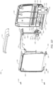
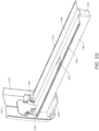
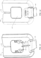
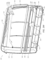
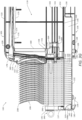
- FIGS. 1A-1S show an example embodiment of a cutlery dispenser 100 as may be described herein.
- the cutlery dispenser 100 may have a generally rectangular shape configured to be oriented in an upright manner, as shown in FIG. 1A , although other suitable shapes and configurations of the cutlery dispenser 100 may be used in other embodiments.
- the cutlery dispenser 100 may be oriented in the upright manner and positioned on a countertop or other support surface in a particular working environment, such as a restaurant, although other suitable orientations and positions of the cutlery dispenser 100 may be used.
- the cutlery dispenser 100 may be configured to be free-standing and portable, such that the cutlery dispenser 100 may be placed on any countertop or other support surface and may be easily moved from one position to another position thereon.
- the cutlery dispenser 100 may be configured to be temporarily or permanently mounted and fixed to a countertop or other support surface.
- the cutlery dispenser 100 may be mounted to a base or other support structure to securely maintain a desired orientation and position of the cutlery dispenser 100 with respect to the countertop or other support structure.
- the cutlery dispenser 100 may be configured to dispense a number of cutlery utensils 200 therefrom one at a time on demand.
- FIGS. 2A and 2B show an example cutlery utensil 200 that may be used with the cutlery dispenser 100.
- the cutlery utensil 200 is shown as a fork in FIGS. 2A and 2B
- the utensil 200 may be any type of cutlery utensil, including, for example, a fork, a spoon, a knife, or a spork.
- the cutlery utensil 200 may be disposable and may be constructed of a moldable material, although other suitable materials may be used.
- the moldable material may include a plastic, a combination of plastics, or other materials suitable for use in forming cutlery utensils.
- the moldable material may include one or more of polystyrene, polyethylene, and polypropylene.
- the cutlery utensil 200 may be constructed of recyclable and/or compostable materials.
- the cutlery utensil 200 may include a functional head 202, a handle 204, and a neck 206.
- the functional head 202 may extend from a first end of the cutlery utensil 200 and may be configured to perform a function to assist a user in the consumption of food.
- the functional head 202 may be configured to cut, pierce, and/or scoop certain types of food for consumption.
- the handle 204 may extend from an opposite second end of the cutlery utensil 200 and may be configured to be grasped by the user for holding and/or manipulating the utensil 200.
- the neck 204 may be positioned between and connect the functional head 202 and the handle 204 and may provide a smooth transition therebetween.
- the cutlery utensil 200 may not include the neck 206, such that the handle 204 is connected to and extends directly from the functional head 202.
- the cutlery utensil 200 may be shaped and contoured as shown in FIGS. 2A and 2B , although other shapes and contours of the utensil 200 may be used.
- the cutlery utensil 200 may include a skewer aperture 208 extending therethrough from a front surface 210 to a back surface 212 of the utensil 200.
- the skewer aperture 208 may be configured to receive a skewer 240 or other type of joinder member or loading member therethrough to facilitate loading of a number of the cutlery utensils 200 into the cutlery dispenser 100, as described below.
- the skewer aperture 208 may be defined in the handle 204 of the cutlery utensil 200 and spaced apart from the second end of the utensil 200, although other suitable locations of the skewer aperture 220 may be used.
- the skewer aperture 208 may have an elongated shape having a length extending along the length of the cutlery utensil 200 and a width extending along the width of the cutlery utensil 200. In certain embodiments, as shown, the skewer aperture 208 may have an elongated racetrack shape having rounded ends, although other shapes of the skewer aperture 208 may be used.
- a thickness T of the handle 204 of the cutlery utensil 200 may vary along the length of the handle 204.
- the handle 204 may include a first portion 214 having a constant or substantially constant thickness T along the length of the first portion 214, and a second portion 216 having a varying thickness T along the length of the second portion 216.
- the front and back surfaces of the handle 204 may be parallel or substantially parallel to one another along the length of the first portion 214, and the front and back surfaces of the handle 204 may be oriented at an acute angle ⁇ relative to one another along the length of the second portion 216.
- the angled shape of the second portion 216 may assist in allowing a number of the cutlery utensils 200 to be fanned when positioned within the cutlery dispenser 100, which may allow a user to easily grasp and dispense a leading cutlery utensil 200.
- the acute angle ⁇ between the front and back surfaces of the handle 204 along the second portion may be between one (1) degree and forty-five (45) degrees, between one (1) degree and thirty (30) degrees, between one (1) degree and twenty (20) degrees, between one (1) degree and ten (10) degrees, or between one (1) degree and six (6) degrees, depending on the degree of fanning desired, although other values of the acute angle ⁇ may be used. It will be appreciated that various types and configurations of cutlery utensils other than the type and configuration of the cutlery utensil 200 shown in FIGS. 2A and 2B may be used with the cutlery dispenser 100.
- a wrapper 230 may enclose at least a portion of the cutlery utensil 200.
- the wrapper 230 may enclose the functional head 202 and at least a portion of the neck 206 of the cutlery utensil 200.
- the wrapper 230 may enclose only the functional head 202 or at least an end portion thereof.
- the wrapper 230 may enclose the entire cutlery utensil 200.
- the wrapper 230 may protect the enclosed portion of the utensil 200 from contamination prior to and during dispensing of the utensil 200 from the cutlery dispenser 100. It will be appreciated that in those embodiments in which the wrapper 230 encloses the entire cutlery utensil 200 or at least covers the portion about the skewer aperture 208, the wrapper 230 will include a corresponding aperture (not shown) therein so as to allow a skewer or the like to pass therethrough.
- the wrapper 230 may be constructed of a thin layer of disposable packaging material, which may be at least substantially sealed to contain the enclosed portion of the cutlery utensil 200 therein.
- the wrapper 230 may be constructed of a plastic, including, for example, polyethylene, and the sealed portions of the wrapper 230 may be formed by heat sealing or glue sealing the plastic around the enclosed portion of the cutlery utensil 200. Other suitable materials of construction may be used to form the wrapper 230, and other suitable methods of forming the sealed regions may be used. It is also contemplated that each of the cutlery utensil embodiments contemplated by the present invention may be wrapper free. In other words, the cutlery dispenser 100 may be used to dispense a cutlery utensil 200 that does not have a wrapper 230 enclosing any portion of the utensil 200.
- FIGS. 2E and 2F show an example skewer 240 that may be used with a number of the cutlery utensils 200 and the cutlery dispenser 100 to facilitate loading of the utensils 200 into the dispenser 100 and/or unloading of the utensils 200 from the dispenser 100.
- the skewer 240 may have an elongated shape and may include a retainer head 242, a handle 244, and a shank 246.
- the retainer head 242 may extend from a first end of the skewer 240 and may be configured to be inserted through the skewer apertures 208 of the cutlery utensils 200 and to releasably retain the utensils 200 on the skewer 240.
- the retainer head 242 may include a pair of retainer arms 248 spaced apart from one another and configured to deflect towards one another when the retainer head 242 is inserted through the skewer aperture 208 of the cutlery utensil 200.
- Each retainer arm 248 may include a barb 250 positioned at or near the free end of the retainer arm 248 and configured to releasably retain the cutlery utensil 200 on the skewer 240 when the retainer head 242 is inserted within the skewer aperture 208 of the utensil 200.
- the handle 244 may extend from an opposite second end of the skewer 240 and may be configured to be grasped by a user for holding and/or manipulating the skewer 240.
- the cross-sectional shape of the handle 244 may be larger than the cross-sectional shape of the skewer aperture 208 of the cutlery utensil 200, such that the handle 244 is prevented from being inserted into the skewer aperture 208.
- the shank 246 may be positioned between and connect the retainer head 242 and the handle 244 and may be configured to be inserted through the skewer apertures 208 of the cutlery utensils 200.
- the skewer 240 may be shaped and contoured as shown in FIGS.
- the skewer 240 may have a more complex configuration than the illustrated embodiment and/or may include multiple components configured to interact with the cutlery utensils 200 and the cutlery dispenser 100.
- FIG. 2G shows the skewer 240 with a number of the cutlery utensils 200 positioned thereon in a stack, such that the utensils 200 are arranged in a nested manner. Although twenty (20) cutlery utensils 200 are shown positioned on the skewer 240 in the illustrated embodiment, the skewer 240 may be configured to retain any suitable number of cutlery utensils 200.
- the skewer 240 may be inserted through the skewer apertures 208 of the cutlery utensils 200, such that the shank 246 and at least a portion of the retainer head 242 are positioned therethrough and the retainer arms 248 retain the cutlery utensils 200 on the skewer 240.
- the corresponding cross-sectional shapes of the shank 246 and the skewer apertures 208 may prevent or restrict the cutlery utensils 200 from rotating relative to the skewer 240, such that all of the cutlery utensils 200 are retained in a common orientation.
- the cutlery utensils 200 may be loaded onto the skewer 240 by inserting the retainer head 242 through the skewer apertures 208 of the utensils 200 and advancing the utensils along the shank 246 toward the handle 244. As the barbs 250 pass through each skewer aperture 208, the retainer arms 248 may deflect towards one another and then assume their relaxed state after the barbs 250 pass through the skewer aperture 208. In this manner, the cutlery utensils 200 may be retained on the shank 246 and/or the retainer head 242 of the skewer 240.
- the cutlery utensils 200 may be removed from the skewer 240 by restraining the relative position of the utensils 200, for example by one or more components of the cutlery dispenser 100 contacting one or more of the utensils 200, and pulling the handle 244 of the skewer 240 away from the utensils 200.
- the handle 244 may be pulled with sufficient force to cause the retainer arms 248 to deflect towards one another such that the barbs 250 may pass through the skewer apertures 208 of the utensils 200.
- the cutlery utensils 200 may be removed from the shank 246 and the retainer head 242 of the skewer 240.
- the skewer 240 may be used to load the stack of the cutlery utensils 200 into the cutlery dispenser 100 in an easy and efficient manner.
- the skewer 240 also may be used to unload a number of the cutlery utensils 200 from the cutlery dispenser 100 in an opposite manner, as described below.
- the cutlery dispenser 100 may have a front 102, a back 104, a top 106, a bottom 108, a first side 110, and a second side 112. It will be appreciated that the nomenclature associated with these sides of the cutlery dispenser 100 are with respect to the upright orientation shown in FIGS. 1A-1D , and that the dispenser 100 may be used in other orientations. As shown, the cutlery dispenser 100 may include a housing 114 that includes a number of walls and defines an interior space 116 therein, inward from the walls of the housing 114.
- the interior space 116 may be configured to receive a number of the cutlery utensils 200 therein and to contain various components of the cutlery dispenser 100 therein.
- the housing 114 may include a number of portions that are separately formed and attached to one another.
- the housing 114 may include a first housing portion 118, a second housing portion 120, and a top cover 122 that are separately formed and attached to one another.
- the first housing portion 118 and the second housing portion 120 may be mirror images or substantially mirror images of one another.
- the first housing portion 118 may define at least a portion of each of the front 102, the back 104, the top 106, the bottom 108, and the first side 110 of the cutlery dispenser 100
- the second housing portion 120 may define at least a portion of each of the front 102, the back 104, the top 106, the bottom 108, and the second side 112 of the cutlery dispenser 100.
- the first housing portion 118 and the second housing portion 120 each may include one or more feet 124 or other leveling features positioned along the bottom thereof and configured to support the cutlery dispenser 100 on a countertop or other support surface in the upright orientation.
- first housing portion 118 and the second housing portion 120 each may include one or more mounting tabs 126 positioned along the bottom surface thereof and configured to securely engage mating receptacles of a base or platform on which the cutlery dispenser 100 may be mounted.
- the mounting tabs 126 may be configured to form a snap fit with the mating receptacles to securely mount the cutlery dispenser 100 to the base or platform.
- the first housing portion 118 and the second housing portion 120 may be securely attached to one another by one or more fasteners 128, such as screws, although other attachment mechanisms may be used.
- the top cover 122 may be positioned over and attached to each of the first housing portion 118 and the second housing portion 120.
- the top cover 122 may define at least a portion of each of the front 102, the back 104, the top 106, the first side 110, and the second side 112 of the cutlery dispenser 100.
- the housing 114 may be constructed of any suitable type of substantially rigid material including thermoplastics, such as polypropylene, metals, such as aluminum, composite materials, or other suitable materials. It will be appreciated that various shapes and configurations of the housing 114 may be used with the cutlery dispenser 100.
- the cutlery dispenser 100 also may include a front cover 130 and a trough 132 attached to the front cover 130.
- the front cover 130 and the trough 132 may be separately formed and attached to one another.
- the front cover 130 and the trough 132 may be attached to one another by one or more fasteners 134, such as screws, although other attachment mechanisms may be used.
- the front cover 130 and the trough 132 may be integrally formed with one another as a single component.
- the front cover 130 and the trough 132 may be configured to move relative to the housing 114 between a closed position, as shown in FIG.
- the front cover 130 and the trough 132 may be configured to slide or translate relative to the housing 114 between the closed position and an open position. It will be appreciated that the front cover 130 and the trough 132 may have a number of open positions, depending on the extent to which the front cover 130 and the trough 132 are moved relative to the housing 114.
- the front cover 130 When the front cover 130 and the trough 132 are in the closed position, the front cover 130 may partially enclose the interior space 116, such that a dispensing opening 136 of the cutlery dispenser 100 is defined between respective portions of the front cover 130 and the housing 114.
- a leading cutlery utensil 200 i.e., the cutlery utensil 200 positioned closest to the dispensing opening 136 and within the interior space 116 of the housing 114
- front cover 130 is positioned along a bottom portion of the front 102 of the cutlery dispenser 100
- the dispensing opening 136 is positioned along a top portion of the front 102 of the dispenser 100.
- the front cover 130 may include an indicator portion 137 positioned along the front of the cover 130 and visible to a user.
- the indicator portion 137 may include an indicator, such as a symbol, a word, or a braille pattern, which indicates the type of cutlery utensil 200 contained within the cutlery dispenser 100 and/or provides a decorative feature for branding or marketing purposes.
- the indicator portion 137 may be removably attached to a remainder of the front cover 130, for example by a snap-fit connection. In this manner, the indicator portion 137 may be removed and replaced with a different indicator portion 137 when the type of cutlery utensil 200 to be dispensed from the dispenser 100 is changed.
- the front cover 130 may include a locking tab 138, which may be positioned along the bottom of the front cover 130 and may be configured to releasably engage a locking receptacle 140 defined in the housing 114 when the front cover 130 is in the closed position.
- the locking tab 138 and the locking receptacle 140 may form a releasable lock to prevent the front cover 130 from inadvertently moving from the closed position to an open position.
- the locking tab 138 may be disengaged from the locking receptacle 140 by deflecting the locking tab 138 away from the locking receptacle 140, thereby allowing the front cover 130 to be moved to an open position.
- the front cover 130 includes a skewer slot 141 defined therein and configured to allow a portion of the skewer 240 to be received within the slot 141.
- the skewer slot 141 facilitates alignment of the skewer 420 relative to the front cover 130 and the overall cutlery dispenser 100 during loading of the cutlery utensils 200 into the dispenser 100 via the skewer 240.
- the skewer slot 141 may extend vertically from the top of the front cover 130, although other orientations and positions of the skewer slot 141 may be used.
- the front cover 130 also may include a wedge protrusion 142 positioned along the vertical interior surface of the front cover 130 and extending inward therefrom.
- the wedge protrusion 142 may be configured to engage a portion of the leading cutlery utensil 200, such as a portion of the handle 204 of the leading cutlery utensil 200, such that the leading cutlery utensil 200 is tilted forward (i.e., toward the front 102 of the dispenser 100) from an upright position to a tilted position and a portion of the leading cutlery utensil 200, such as the functional head 202 of the leading cutlery utensil 200, extends at least partially through the dispensing opening 136 and outside of the interior space 116.
- the wedge protrusion 142 may cause the leading cutlery utensil 200 and a number of subsequent cutlery utensils 200 (i.e., cutlery utensils 200 positioned further from the dispensing opening 136 than the leading cutlery utensil 200) to assume a fanned arrangement, with the functional heads 202 of these utensils 200 spaced apart from one another to facilitate dispensing.
- the wedge protrusion 142 may include one or more contact surfaces 144 configured to engage the front surface of the handle 204 of the leading cutlery utensil 200 such that the leading cutlery utensil 200 is tilted from the upright position to the tilted position.
- the trough 132 may extend inward from the front cover 130 and may move therewith when the front cover 130 is moved between the closed position and an open position.
- the trough 132 may have an elongated shape and may include a base 146 having a U-shaped cross-sectional shape, and a pair of flanges 148 extending laterally from the base 146.
- the base 146 may be configured to receive a portion of each of the cutlery utensils 200 in the cutlery dispenser 100.
- the base 146 may be configured to receive a portion of the handle 204 of each of the cutlery utensils 200 therein.
- the base 146 may be configured to receive a portion of the functional head 202 of each of the cutlery utensils 200 therein.
- each of the flanges 148 may be movably received between a pair of guide rails 150 of the housing 114.
- the guide rails 150 may guide the sliding horizontal movement of the trough 132 relative to the housing 114 and may prevent or restrict vertical movement of the trough 132 relative to the housing 114.
- the trough 132 may include a stop tab 152 configured to engage a stop protrusion 154 of the housing 114 to limit the sliding movement of the trough 132 relative to the housing 114.
- the stop tab 152 may be positioned on one of the flanges 148 of the trough 132, although other positions of the stop tab 152 may be used.
- the stop tab 152 effectively may define a fully open position of the front cover 130 and the trough 132 relative to the housing 114. In this manner, the stop tab 152 may prevent or restrict the trough 132 from being completely removed from the interior space 116 of the housing 114.
- the trough 132 also may include a stop wall 155 positioned at or near the end of the trough 132 opposite the front cover 130 and extending vertically along the height of the base 146.
- the cutlery dispenser 100 also may include a pushing assembly 156 movably positioned within the interior space 116 of the dispenser 100 and configured to push or advance the cutlery utensils 200 toward the front 102 of the dispenser 100.
- the pusher assembly 156 may include a support member 158 and one or more biasing members 160.
- the support member 158 may be configured to translate or slide relative to the housing 114 in a direction extending from the front 102 of the dispenser 100 to the back 104 of the dispenser 100, and the biasing member 160 may be configured to bias the support member 158 toward the front 102 of the dispenser 100 and into engagement with the trailing cutlery utensil 200 loaded in the dispenser 100.
- the support member 158 may include a contact surface 162 positioned along the front of the support member 158 and configured to engage the back surface of the trailing cutlery utensil 200.
- the support member 158 also may include a number of arms 164 extending laterally and configured to movably engage respective guide rails 166 of the housing 114. In this manner, the guide rails 166 may guide the sliding horizontal movement of the support member 158 relative to the housing 114 and may prevent or restrict vertical movement of the support member 158 relative to the housing 114.
- the support member 158 also may include a guide post 168 extending vertically upward and configured to movably engage a follower arm 170 of the cutlery dispenser 100.
- the follower arm 170 may include a number of indicators 178 configured to indicate a fill level of the cutlery utensils 200 loaded within the interior space 116 of the cutlery dispenser 100 and/or to indicate whether additional cutlery utensils 200 may be loaded into the interior space 116 of the dispenser 100.
- the follower arm 170 may include three (3) indicators 178, although any number of the indicators 178 may be used.
- a first indicator 178a may indicate that the dispenser 100 is full or nearly full
- a second indicator 178b may indicate that the dispenser 100 is partially full
- a third indicator 178c may indicate that the dispenser 100 is empty or nearly empty.
- the indicators 178 may be colored-coded, with each indicator 178 being a different color.
- the first indicator 178a may be green
- the second indicator 178b may be yellow
- the third indicator 178c may be red, although other colors may be used for the indicators 178.
- the indicators 178 may indicate whether an additional stack of the cutlery utensils 200 (i.e., the number of the cutlery utensils 200 that may be loaded on the skewer 240 at once) may be loaded into the dispenser 100.
- the first indicator 178a may indicate that no additional full stacks of the utensils 200 may be loaded into the dispenser 100
- the second indicator 178b may indicate that one additional stack of the utensils 200 may be loaded into the dispenser 100
- the third indicator 178c may indicate that two additional stacks of the utensils 200 may be loaded into the dispenser 100.
- the indicators 178 may provide any type of visual indication, such as colors, symbols, numbers, or words. During use of the cutlery dispenser 100, one of the indicators 178 may be visible through an indicator window 180 of the housing 114, while the remaining indicators 178 are hidden from view. Other configurations may allow for a transition between two of the indicators 178.
- the indicator window 180 may be positioned along the front 102 of the dispenser 100, although other positions of the indicator window 180, such as along the top 106 or one of the sides 110, 112 of the dispenser 100, may be used.
- the indicator 178 that is visible through the indicator window 180 may allow a user to determine the fill level of the cutlery utensils 200 loaded within the interior space 116 of the cutlery dispenser 100 and/or whether additional utensils 200 may be loaded into the interior space 116 of the dispenser 100.
- the indicators 178 are shown as being part of the follower arm 170 in the illustrated embodiment, the indicators 178 alternatively may be part of the support member 158, and the indicator window 180 may be configured to allow the different indicators 178 to be viewed as the support member 158 translates relative to the housing 114.
- each sweeper arm 182 may include a barb 184 positioned along a front end of the sweeper arm 182 and configured to engage the cutlery utensils 200.
- the barb 184 may include a lead-in surface 186 configured to engage the back surface of a cutlery utensil 200 as the utensil 200 is inserted between the sweeper arms 182, and a contact surface 188 configured to engage the front surface of the cutlery utensil 200 after the utensil 200 is inserted past the barb 184.
- the sweeper arms 182 may be spaced apart and configured to deflect away from one another when the cutlery utensil 200 engages the lead-in surfaces 186 and then return to their original, relaxed position after the utensil 200 is inserted past the barb 184.
- the cutlery utensil 200 subsequently may be biased into engagement with the contact surfaces 188 by the pushing assembly 156.
- the sweeper arms 182 may engage the leading cutlery utensil 200 and maintain the loaded cutlery utensils 200 within the interior space 116 of the dispenser 100 when the front cover 130 is in an open position and may disengage (i.e., be spaced apart from and not in contact with) the leading cutlery utensil 200 when the front cover 130 is in the closed position.
- FIGS. 3A-3D illustrate an example method of loading a number of the cutlery utensils 200 into the cutlery dispenser 100 and dispensing the loaded cutlery utensils 200 (i.e., the utensils 200 positioned within the interior space 116 of the housing 114) from the cutlery dispenser 100.
- the front cover 130 may be moved relative to the housing 114 from the closed position to an open position, as shown in FIG. 3A .
- the locking tab 138 of the front cover 130 may be depressed to disengage the locking receptacle 140 of the housing 114, and the front cover 130 may be pulled away from the front of the housing 114 along with the trough 132.
- the front cover 130 may be pulled until the stop tab 152 of the trough 132 engages the stop protrusion 154 of the housing 114, such that the front cover 130 and the trough 132 are in the fully open position, as shown.
- the handles 204 of the cutlery utensils 200 may be inserted into the base 146 of the trough 132, as shown.
- the cutlery utensils 200 may be oriented in an upright or substantially upright manner with the functional heads 202 of the utensils 200 positioned above the handles 204 of the utensils 200.
- This orientation of the cutlery utensils 200 advantageously may allow the cutlery dispenser 100 to receive and dispense any suitable type of utensil 200 (e.g., forks, spoons, knives, sporks, etc.) having a handle 204 configured to be received within the trough 132 and a body that is sized to functionally fit within the dispenser 100.
- the front cover 130 and the trough 132 may be moved relative to the housing 114 from the open position to the closed position, as shown in FIG. 3C .
- the cutlery utensils 200 may pass between the sweeper arms 182 and into the interior space 116 of the dispenser 100, each utensil 200 engaging the lead-in surfaces 186 of the barbs 184 and deflecting the sweeper arms 182 away from one another as the utensil 200 is inserted therebetween.
- the trailing cutlery utensil 200 should engage the contact surface 162 of the support member 158, thereby moving the support member 158 toward the back 104 of the dispenser 100 and unfurling the biasing member 160 toward the back 104 of the dispenser 100.
- the biasing member 160 may bias the support member 158 toward the front 102 of the dispenser 100 such that the contact surface 162 maintains engagement with the back surface of the trailing cutlery utensil 200.
- the guide post 168 of the support member 158 may move along the contoured contact surface 174 of the follower arm 170 such that the follower arm 170 pivots upward relative to the housing 114 and the visible indicator 178 indicates the fill level of the cutlery utensils 200 loaded in the dispenser 100 or available capacity of the dispenser 100.
- the locking tab 138 of the front cover 130 may engage the locking receptacle 140 of the housing 114, thereby preventing the front cover 130 from being inadvertently moved toward an open position.
- the skewer 240 may be removed from the skewer apertures 208 of the cutlery utensils 200, via the skewer slot 141 of the front cover 130, and from the overall cutlery dispenser 100.
- the skewer 240 may be removed from the skewer apertures 208 and the skewer slot 141 by pulling the skewer 240 away from the front cover 130, via the handle 244, while the cutlery utensils 200 are restrained by the sweeper arms 182 and/or the front cover 130.
- the pushing assembly 156 may move the cutlery utensils 200 toward the front 102 of the dispenser 100 and into engagement with the wedge protrusion 142, as shown in FIG. 3D .
- the biasing member 160 is shown biasing the support member 158 against the trailing cutlery utensil 200 such that the cutlery utensils 200 are compressed together and the leading cutlery utensil 200 engages the wedge protrusion 142.
- the front surface of the handle 204 of the leading cutlery utensil 200 engages the wedge protrusion 142 such that the leading cutlery utensil 200 is tilted toward the front 102 of the dispenser 100 and at least a portion of the functional head 202 of the leading cutlery utensil 200 extends through the dispensing opening 136 and out of the dispenser 100.
- the handle 204 of the leading cutlery utensil 200 engages the wedge protrusion 142
- the handle 204 desirably is disengaged and spaced apart from the sweeper arms 182.
- the handle 204 of the leading cutlery utensil 200 no longer engages the contact surfaces 188 of the sweeper arms 182 when the front cover 130 is closed.
- the angled shape of the wedge protrusion 142 and the angled shape of the second portions 216 of the cutlery utensils 200 may cause the leading cutlery utensil 200 and a number of the subsequent cutlery utensils 200 to assume a fanned arrangement, as shown in FIG. 3D , with portions of the handles 204 of such utensils 200 abutting one another and the functional heads 202 of such utensils 200 spaced apart from one another.
- the fanned arrangement of the cutlery utensils 200 may allow a user to easily grasp and pull the functional head 202 of the leading cutlery utensil 200, such that the leading cutlery utensil 200 may be removed from the cutlery dispenser 100.
- the biasing member 160 may move the support member 158 toward the front 102 of the dispenser 100 such that the contact surface 162 of the support member 158 maintains engagement with the back surface of the trailing cutlery utensil 200 and all of the cutlery utensils 200 move into position for a subsequent dispense.
- FIGS. 3E-3G illustrate the function of the sweeper arms 182 when the front cover 130 is moved to an open position while a number of the cutlery utensils 200 remain loaded in the cutlery dispenser 100.
- the cutlery utensils 200 may move toward the front 102 of the dispenser 100 such that the leading loaded cutlery utensil 200 engages the contact surfaces 188 of the sweeper arms 182 and the cutlery utensils 200 assume an upright position.
- additional cutlery utensils 200 may be loaded into the cutlery dispenser 182 via the skewer 240, as shown in FIG. 3G .
- Loading of the additional cutlery utensils 200 may be carried out in the manner described above with respect to FIGS. 3A-3D .
- the skewer 240 also may be used to facilitate removal of the loaded cutlery utensils 200 from the cutlery dispenser 100.
- the skewer 240 may be inserted through the skewer slot 141 of the front cover 130 and through the skewer apertures 208 of the loaded cutlery utensils 200, such that the utensils 200 are retained by the skewer 240.
- the front cover 130 then may be moved to an open position, and the cutlery utensils 200 may be pulled out of the interior space 116 of the housing 114 via the skewer 240. If more utensils remain than can be removed on one skewer, the process may be repeated until all utensils are removed.
Landscapes
- Table Equipment (AREA)
Claims (5)
- Besteckspender (100) zum Ausgeben von Besteckutensilien (200), wobei der Spender (100) umfasst:ein Gehäuse (114), das einen Innenraum (116) umfasst, der konfiguriert ist, um eine Vielzahl von darin geladenen Besteckutensilien (200) aufzunehmen;eine vordere Abdeckung (130), die einen Abschnitt des Innenraums (116) umschließt und konfiguriert ist, um sich in Bezug zum Gehäuse (114) zwischen einer geschlossenen Position zum Ausgeben der geladenen Besteckutensilien (200) aus dem Innenraum (116), und einer offenen Position zum Laden der Besteckutensilien (200) in den Innenraum (116) zu bewegen;und eine Ausgabeöffnung, die durch das Gehäuse (114) und die vordere Abdeckung (130) definiert ist und konfiguriert ist, um zu ermöglichen, dass die geladenen Besteckutensilien (200) dort hindurch ausgegeben werden,wobei die vordere Abdeckung (130) entlang eines unteren Abschnitts einer Vorderseite (102) des Besteckspenders (100) positioniert ist und die Ausgabeöffnung (136) entlang eines oberen Abschnitts der Vorderseite (102) des Besteckspenders (100) positioniert ist,wobei die Abdeckung (130) einen Spießschlitz (141) umfasst, der sich von einer Oberseite der vorderen Abdeckung (130) erstreckt und konfiguriert ist, um einen Spieß (240) aufzunehmen, um Laden der Besteckutensilien (200) in den Innenraum (116) zu erleichtern, wobei der Spießschlitz (141) angepasst ist, um die Ausrichtung eines Spießes (420) in Bezug zur vorderen Abdeckung (130) und dem Besteckspender (100) beim Laden der Besteckutensilien (200) in den Besteckspender (100) über den Spieß (240) zu erleichtern .
- Besteckspender (100) nach Anspruch 1, wobei sich der Spießschlitz (141) vertikal erstreckt.
- Besteckspender (100) nach einem der Ansprüche 1 bis 2, wobei die vordere Abdeckung (130) einen Indikatorabschnitt (137) beinhaltet, der entlang der Vorderseite der vorderen Abdeckung (130) und für einen Benutzer sichtbar positioniert ist, wobei der Indikatorabschnitt (137) eine Angabe beinhaltet, die die Art des im Besteckspender (100) enthaltenen Besteckutensils (200) angibt.
- Besteckspender (100) nach einem der Ansprüche 1 bis 3, wobei die vordere Abdeckung (130) eine Verriegelungslasche (138) beinhaltet, die entlang der Unterseite der vorderen Abdeckung (130) positioniert ist und konfiguriert ist, um lösbar in einen im Gehäuse (114) definierten Verriegelungsbehälter (140) einzugreifen, wenn die vordere Abdeckung (130) in der geschlossenen Position ist.
- Besteckspender (100) nach einem der Ansprüche 1 bis 4, wobei die vordere Abdeckung (130) einen Keilvorsprung (142) beinhalten kann, der entlang der vertikalen Innenfläche der vorderen Abdeckung (130) positioniert ist und sich von dieser nach innen erstreckt.
Applications Claiming Priority (3)
| Application Number | Priority Date | Filing Date | Title |
|---|---|---|---|
| US201662349559P | 2016-06-13 | 2016-06-13 | |
| PCT/US2017/037233 WO2017218521A1 (en) | 2016-06-13 | 2017-06-13 | Cutlery dispenser |
| EP17813926.7A EP3468421B1 (de) | 2016-06-13 | 2017-06-13 | Besteckspender |
Related Parent Applications (2)
| Application Number | Title | Priority Date | Filing Date |
|---|---|---|---|
| EP17813926.7A Division-Into EP3468421B1 (de) | 2016-06-13 | 2017-06-13 | Besteckspender |
| EP17813926.7A Division EP3468421B1 (de) | 2016-06-13 | 2017-06-13 | Besteckspender |
Publications (2)
| Publication Number | Publication Date |
|---|---|
| EP3689190A1 EP3689190A1 (de) | 2020-08-05 |
| EP3689190B1 true EP3689190B1 (de) | 2025-01-01 |
Family
ID=60573461
Family Applications (2)
| Application Number | Title | Priority Date | Filing Date |
|---|---|---|---|
| EP20164317.8A Active EP3689190B1 (de) | 2016-06-13 | 2017-06-13 | Besteckspender |
| EP17813926.7A Active EP3468421B1 (de) | 2016-06-13 | 2017-06-13 | Besteckspender |
Family Applications After (1)
| Application Number | Title | Priority Date | Filing Date |
|---|---|---|---|
| EP17813926.7A Active EP3468421B1 (de) | 2016-06-13 | 2017-06-13 | Besteckspender |
Country Status (5)
| Country | Link |
|---|---|
| US (1) | US10327567B2 (de) |
| EP (2) | EP3689190B1 (de) |
| CN (1) | CN109310220B (de) |
| MX (1) | MX2018015632A (de) |
| WO (1) | WO2017218521A1 (de) |
Families Citing this family (12)
| Publication number | Priority date | Publication date | Assignee | Title |
|---|---|---|---|---|
| WO2018017782A1 (en) * | 2016-07-20 | 2018-01-25 | Jade Group International Llc | Skewer for loading cutlery |
| US10842293B2 (en) | 2018-01-24 | 2020-11-24 | Gpcp Ip Holdings Llc | Utensil dispensers having improved prime mechanism |
| US10631665B2 (en) * | 2018-01-24 | 2020-04-28 | Gpcp Ip Holdings Llc | Cutlery dispensing assemblies and methods |
| US10779661B2 (en) | 2018-01-24 | 2020-09-22 | Gpcp Ip Holdings Llc | Utensil dispensers with glide mechanism for loading |
| US10881220B2 (en) * | 2018-01-24 | 2021-01-05 | Gpcp Ip Holdings Llc | Utensil dispensers with interlock mechanism |
| US11147393B2 (en) | 2018-01-24 | 2021-10-19 | Gpcp Ip Holdings Llc | Utensil dispenser with rail system |
| US10881221B2 (en) | 2018-01-24 | 2021-01-05 | Gpcp Ip Holdings Llc | Utensil dispensers with stack gauge |
| EP4527256A3 (de) | 2018-09-21 | 2025-06-04 | GPCP IP Holdings LLC | Spender für einwegutensilien |
| WO2020172699A1 (en) * | 2019-02-26 | 2020-09-03 | Take it Once Pty Ltd | Stackable cutlery utensil, cutlery dispenser and system for dispensing cutlery utensils |
| USD920052S1 (en) * | 2019-08-30 | 2021-05-25 | Kolor Magnetic (Shenzhen) Co., Ltd. | Utensil dispenser |
| DE102020205378A1 (de) | 2020-04-28 | 2021-10-28 | GastroGast Gruber e.K. | Besteckaufbewahrungsvorrichtung |
| DE102020122534A1 (de) | 2020-08-28 | 2022-03-03 | Shahin Farzin | Besteckspender zur Ausgabe von Besteckteilen |
Family Cites Families (61)
| Publication number | Priority date | Publication date | Assignee | Title |
|---|---|---|---|---|
| US1560938A (en) | 1924-03-08 | 1925-11-10 | John T Lund | Ingot carrier |
| US2431121A (en) | 1944-11-09 | 1947-11-18 | Melmoth W Hunter | Token or like dispensing device |
| US2646874A (en) | 1947-08-08 | 1953-07-28 | Gillette Co | Blade dispensing magazine |
| US2503741A (en) | 1948-02-21 | 1950-04-11 | Johnson Andrew | Ammunition dispensing device |
| US2671555A (en) | 1949-12-15 | 1954-03-09 | Gillette Co | Blade dispenser with used blade compartment |
| US3180489A (en) | 1963-11-29 | 1965-04-27 | Fmc Corp | Seal assembly |
| US3749234A (en) | 1968-10-25 | 1973-07-31 | Distefano D | Cigarette dispensing package |
| US3679096A (en) | 1970-04-22 | 1972-07-25 | Malcolm E Musser | Bag holder and opening apparatus |
| US3861563A (en) | 1973-04-12 | 1975-01-21 | Levelator Corp | Self-leveling dispenser with article separator |
| US4005801A (en) | 1976-01-14 | 1977-02-01 | Musser Malcolm E | Bag storing and dispensing apparatus |
| PL116223B1 (en) | 1977-08-05 | 1981-05-30 | Akad Rolnicza | Process for the preparation of subsoil for plant growing |
| US4530445A (en) * | 1982-09-28 | 1985-07-23 | Decker David E | Paper clip holder |
| USD305709S (en) | 1987-02-24 | 1990-01-30 | Blignaut James C | Combined key storage stand and carrier |
| US4798319A (en) | 1987-09-25 | 1989-01-17 | James Jr Virtious | Ball caddy |
| US5131562A (en) | 1991-01-28 | 1992-07-21 | Brown Anthony P | Dispenser for soft drink lids and the like |
| US5263596A (en) | 1991-12-02 | 1993-11-23 | Williams David R | Medication dispenser station sub-assembly |
| US6257443B1 (en) * | 1998-08-31 | 2001-07-10 | Alwin Manufacturing Co. | Napkin holder |
| IT1307781B1 (it) | 1999-07-16 | 2001-11-19 | Stefano Casebasse | Una confezione per una pluralita' di palette per gelato ed altro,manipolabili per rifornire distributori di palette. |
| IT1307782B1 (it) * | 1999-07-16 | 2001-11-19 | Stefano Casebasse | Dispositivo distributore di palette (o cucchiaini) a perdere pergelati ed altro, con congegno per l'estrazione a scorrimento della |
| US6250498B1 (en) | 1999-10-26 | 2001-06-26 | Scott Lovejoy | Spoon dispenser |
| AU2003272162A1 (en) | 2002-09-26 | 2004-04-19 | Benedykt Prusecki | Method of disposable cutlery dispensing, stack of cutlery and dispenser therefor |
| US6832694B2 (en) * | 2002-11-07 | 2004-12-21 | Fort James Corporation | Dispenser for cutlery utensils |
| US7900797B1 (en) | 2004-01-12 | 2011-03-08 | Daryl Dean Witcraft | Lid separator and dispensing device |
| AU2004319268B2 (en) * | 2004-05-07 | 2010-10-28 | Sca Hygiene Products Ab | Apparatus for serially dispensing folded sheet products |
| US7669732B2 (en) | 2005-10-25 | 2010-03-02 | Imi Cornelius Inc. | Cup lid dispenser |
| FR2893166B1 (fr) | 2005-11-08 | 2007-12-21 | Philippe Leonetti | Distributeur de produits alimentaires notamment de boissons. |
| US20070131705A1 (en) | 2005-12-09 | 2007-06-14 | Behravesh Casey B | Object dispenser |
| CN101053471A (zh) * | 2006-04-14 | 2007-10-17 | 郭永利 | 餐具移送机构及具有此移送机构的餐具供给装置 |
| US7424957B1 (en) | 2006-05-24 | 2008-09-16 | Henschel-Steinau, Inc. | Front-loading display and dispensing apparatus |
| ITRE20060068A1 (it) | 2006-06-05 | 2007-12-06 | Ducale Macchine Da Caffe | ¿sistema per l¿erogazione automatica di posate¿ |
| JP2010508993A (ja) * | 2006-11-07 | 2010-03-25 | ディクシー コンスーマー プロダクツ エルエルシー | カトラリー分配装置およびカトラリー分配方法 |
| USD584084S1 (en) | 2007-07-11 | 2009-01-06 | Terence Tucker | Refillable cutlery dispenser magazine |
| USD607245S1 (en) | 2007-07-11 | 2010-01-05 | Terence Tucker | Slidable cutlery dispenser magazine |
| US7690518B2 (en) | 2007-07-17 | 2010-04-06 | Sonoco Development, Inc. | Front-loading rack for displaying and first-in, first-out dispensing of products |
| US20090194557A1 (en) | 2008-01-30 | 2009-08-06 | Van Deursen Gary E | Blade dispenser |
| US8360273B2 (en) * | 2008-10-08 | 2013-01-29 | Dixie Consumer Products Llc | Cutlery utensil dispenser |
| US8701932B2 (en) * | 2008-10-08 | 2014-04-22 | Dixie Consumer Products Llc | Cutlery dispenser trays |
| US20100147869A1 (en) | 2008-12-12 | 2010-06-17 | The Stanley Works | Blade dispenser |
| US8272533B1 (en) * | 2010-07-07 | 2012-09-25 | D Amelia Anthony | No touch utensil dispenser |
| US11083316B1 (en) | 2010-07-07 | 2021-08-10 | Waddington North America, Inc. | Recyclable and dispensable cutlery utensil |
| US9049949B1 (en) | 2011-05-06 | 2015-06-09 | James M. Taylor | Drink container lid dispenser |
| US9439518B2 (en) * | 2011-08-19 | 2016-09-13 | Dixie Consumer Products Llc | Cutlery dispenser |
| US9049948B2 (en) * | 2012-01-27 | 2015-06-09 | Us Foods, Inc. | Utensil dispenser |
| US9226598B1 (en) | 2012-04-24 | 2016-01-05 | William J Knope | Single-serve sanitary module dispensing system |
| US9986876B2 (en) | 2012-09-06 | 2018-06-05 | Sca Hygiene Products Ab | Dispenser for sheet products |
| EP3030501B1 (de) | 2013-08-08 | 2018-12-05 | GPCP IP Holdings LLC | Frontbeschickbarer besteckspender |
| US9332861B2 (en) * | 2013-08-19 | 2016-05-10 | Dixie Consumer Products Llc | Cutlery dispenser and methods of use |
| US9560920B2 (en) * | 2014-04-11 | 2017-02-07 | Dixie Consumer Products Llc | Forward advancing cutlery dispenser |
| CN203828595U (zh) | 2014-04-21 | 2014-09-17 | 宁波家联塑料科技有限公司 | 一种餐具高速自动分发器 |
| CN103919422B (zh) | 2014-04-21 | 2015-07-08 | 宁波家联塑料科技有限公司 | 一种餐具叉子分发器 |
| CN203828512U (zh) * | 2014-04-21 | 2014-09-17 | 宁波家联塑料科技有限公司 | 一种一次性餐具自动分发盒 |
| CN103960919B (zh) | 2014-04-21 | 2017-02-08 | 宁波家联塑料科技有限公司 | 一种一次性餐具自动分发盒 |
| CN203828584U (zh) * | 2014-04-21 | 2014-09-17 | 宁波家联塑料科技有限公司 | 一种餐具刀具分发器 |
| US9700153B2 (en) | 2014-09-30 | 2017-07-11 | Gadsden Coffee Company, Inc. | Automated hygienic cutlery dispenser |
| CN204617801U (zh) | 2015-04-02 | 2015-09-09 | 谢文龙 | 自动餐具盒 |
| CN204617815U (zh) * | 2015-05-13 | 2015-09-09 | 台州富岭塑胶有限公司 | 一种餐具分配机构 |
| USD783303S1 (en) | 2015-07-20 | 2017-04-11 | Dixie Consumer Products Llc | Cutlery dispenser |
| WO2017139525A1 (en) | 2016-02-10 | 2017-08-17 | Jade Group International Llc | Band for loading cutlery |
| ES2929042T3 (es) | 2016-04-05 | 2022-11-24 | Waddington North America Inc | Sistema y método de apilado de cubertería |
| WO2018006062A1 (en) | 2016-06-30 | 2018-01-04 | Jade Group International Llc | Cutlery dispenser |
| CN110325079B (zh) | 2017-05-22 | 2021-03-23 | R·F·哈伯德 | 器皿分配器系统 |
-
2017
- 2017-06-13 MX MX2018015632A patent/MX2018015632A/es unknown
- 2017-06-13 CN CN201780036630.6A patent/CN109310220B/zh active Active
- 2017-06-13 EP EP20164317.8A patent/EP3689190B1/de active Active
- 2017-06-13 WO PCT/US2017/037233 patent/WO2017218521A1/en not_active Ceased
- 2017-06-13 EP EP17813926.7A patent/EP3468421B1/de active Active
- 2017-06-13 US US15/621,247 patent/US10327567B2/en active Active
Also Published As
| Publication number | Publication date |
|---|---|
| US10327567B2 (en) | 2019-06-25 |
| CN109310220A (zh) | 2019-02-05 |
| EP3468421B1 (de) | 2024-08-07 |
| EP3468421A4 (de) | 2020-01-22 |
| CA3025872A1 (en) | 2017-12-21 |
| EP3468421A1 (de) | 2019-04-17 |
| EP3689190A1 (de) | 2020-08-05 |
| CN109310220B (zh) | 2021-03-19 |
| US20170354270A1 (en) | 2017-12-14 |
| WO2017218521A1 (en) | 2017-12-21 |
| MX2018015632A (es) | 2019-09-27 |
Similar Documents
| Publication | Publication Date | Title |
|---|---|---|
| EP3689190B1 (de) | Besteckspender | |
| EP3128874B1 (de) | Besteckspender mit vorschub | |
| EP3030501B1 (de) | Frontbeschickbarer besteckspender | |
| USRE48104E1 (en) | Utensil dispenser | |
| US20190119023A1 (en) | Cutlery dispenser and related methods | |
| US10413089B2 (en) | Cutlery dispenser | |
| US7784625B2 (en) | Storage article organizer | |
| WO2017139527A1 (en) | Skewer for loading cutlery | |
| US6722526B1 (en) | Cookie/cracker dispenser | |
| CA3025872C (en) | Cutlery dispenser | |
| HK40007556B (en) | Cutlery dispenser | |
| HK40007556A (en) | Cutlery dispenser | |
| US20240415297A1 (en) | Wood cutlery dispenser for wooden cutleries | |
| US12116199B2 (en) | Dispenser assembly for disposable lids | |
| US5860562A (en) | Package dispenser | |
| US5503298A (en) | Bagel dispenser | |
| HK1231342B (zh) | 向前前进的餐具分配器 |
Legal Events
| Date | Code | Title | Description |
|---|---|---|---|
| PUAI | Public reference made under article 153(3) epc to a published international application that has entered the european phase |
Free format text: ORIGINAL CODE: 0009012 |
|
| STAA | Information on the status of an ep patent application or granted ep patent |
Free format text: STATUS: THE APPLICATION HAS BEEN PUBLISHED |
|
| AC | Divisional application: reference to earlier application |
Ref document number: 3468421 Country of ref document: EP Kind code of ref document: P |
|
| AK | Designated contracting states |
Kind code of ref document: A1 Designated state(s): AL AT BE BG CH CY CZ DE DK EE ES FI FR GB GR HR HU IE IS IT LI LT LU LV MC MK MT NL NO PL PT RO RS SE SI SK SM TR |
|
| STAA | Information on the status of an ep patent application or granted ep patent |
Free format text: STATUS: REQUEST FOR EXAMINATION WAS MADE |
|
| 17P | Request for examination filed |
Effective date: 20210203 |
|
| RBV | Designated contracting states (corrected) |
Designated state(s): AL AT BE BG CH CY CZ DE DK EE ES FI FR GB GR HR HU IE IS IT LI LT LU LV MC MK MT NL NO PL PT RO RS SE SI SK SM TR |
|
| STAA | Information on the status of an ep patent application or granted ep patent |
Free format text: STATUS: EXAMINATION IS IN PROGRESS |
|
| 17Q | First examination report despatched |
Effective date: 20210628 |
|
| P01 | Opt-out of the competence of the unified patent court (upc) registered |
Effective date: 20230528 |
|
| GRAP | Despatch of communication of intention to grant a patent |
Free format text: ORIGINAL CODE: EPIDOSNIGR1 |
|
| STAA | Information on the status of an ep patent application or granted ep patent |
Free format text: STATUS: GRANT OF PATENT IS INTENDED |
|
| INTG | Intention to grant announced |
Effective date: 20240229 |
|
| GRAJ | Information related to disapproval of communication of intention to grant by the applicant or resumption of examination proceedings by the epo deleted |
Free format text: ORIGINAL CODE: EPIDOSDIGR1 |
|
| STAA | Information on the status of an ep patent application or granted ep patent |
Free format text: STATUS: EXAMINATION IS IN PROGRESS |
|
| INTC | Intention to grant announced (deleted) | ||
| GRAP | Despatch of communication of intention to grant a patent |
Free format text: ORIGINAL CODE: EPIDOSNIGR1 |
|
| STAA | Information on the status of an ep patent application or granted ep patent |
Free format text: STATUS: GRANT OF PATENT IS INTENDED |
|
| INTG | Intention to grant announced |
Effective date: 20240904 |
|
| GRAS | Grant fee paid |
Free format text: ORIGINAL CODE: EPIDOSNIGR3 |
|
| GRAA | (expected) grant |
Free format text: ORIGINAL CODE: 0009210 |
|
| STAA | Information on the status of an ep patent application or granted ep patent |
Free format text: STATUS: THE PATENT HAS BEEN GRANTED |
|
| AC | Divisional application: reference to earlier application |
Ref document number: 3468421 Country of ref document: EP Kind code of ref document: P |
|
| AK | Designated contracting states |
Kind code of ref document: B1 Designated state(s): AL AT BE BG CH CY CZ DE DK EE ES FI FR GB GR HR HU IE IS IT LI LT LU LV MC MK MT NL NO PL PT RO RS SE SI SK SM TR |
|
| REG | Reference to a national code |
Ref country code: GB Ref legal event code: FG4D |
|
| REG | Reference to a national code |
Ref country code: DE Ref legal event code: R096 Ref document number: 602017087172 Country of ref document: DE |
|
| REG | Reference to a national code |
Ref country code: CH Ref legal event code: EP |
|
| REG | Reference to a national code |
Ref country code: IE Ref legal event code: FG4D |
|
| REG | Reference to a national code |
Ref country code: LT Ref legal event code: MG9D |
|
| REG | Reference to a national code |
Ref country code: NL Ref legal event code: MP Effective date: 20250101 |
|
| REG | Reference to a national code |
Ref country code: AT Ref legal event code: MK05 Ref document number: 1755358 Country of ref document: AT Kind code of ref document: T Effective date: 20250101 |
|
| PG25 | Lapsed in a contracting state [announced via postgrant information from national office to epo] |
Ref country code: NL Free format text: LAPSE BECAUSE OF FAILURE TO SUBMIT A TRANSLATION OF THE DESCRIPTION OR TO PAY THE FEE WITHIN THE PRESCRIBED TIME-LIMIT Effective date: 20250101 |
|
| PG25 | Lapsed in a contracting state [announced via postgrant information from national office to epo] |
Ref country code: FI Free format text: LAPSE BECAUSE OF FAILURE TO SUBMIT A TRANSLATION OF THE DESCRIPTION OR TO PAY THE FEE WITHIN THE PRESCRIBED TIME-LIMIT Effective date: 20250101 |
|
| PG25 | Lapsed in a contracting state [announced via postgrant information from national office to epo] |
Ref country code: PL Free format text: LAPSE BECAUSE OF FAILURE TO SUBMIT A TRANSLATION OF THE DESCRIPTION OR TO PAY THE FEE WITHIN THE PRESCRIBED TIME-LIMIT Effective date: 20250101 |
|
| PGFP | Annual fee paid to national office [announced via postgrant information from national office to epo] |
Ref country code: DE Payment date: 20250402 Year of fee payment: 9 |
|
| PG25 | Lapsed in a contracting state [announced via postgrant information from national office to epo] |
Ref country code: ES Free format text: LAPSE BECAUSE OF FAILURE TO SUBMIT A TRANSLATION OF THE DESCRIPTION OR TO PAY THE FEE WITHIN THE PRESCRIBED TIME-LIMIT Effective date: 20250101 |
|
| PGFP | Annual fee paid to national office [announced via postgrant information from national office to epo] |
Ref country code: GB Payment date: 20250401 Year of fee payment: 9 |
|
| PG25 | Lapsed in a contracting state [announced via postgrant information from national office to epo] |
Ref country code: IS Free format text: LAPSE BECAUSE OF FAILURE TO SUBMIT A TRANSLATION OF THE DESCRIPTION OR TO PAY THE FEE WITHIN THE PRESCRIBED TIME-LIMIT Effective date: 20250501 Ref country code: NO Free format text: LAPSE BECAUSE OF FAILURE TO SUBMIT A TRANSLATION OF THE DESCRIPTION OR TO PAY THE FEE WITHIN THE PRESCRIBED TIME-LIMIT Effective date: 20250401 |
|
| PG25 | Lapsed in a contracting state [announced via postgrant information from national office to epo] |
Ref country code: HR Free format text: LAPSE BECAUSE OF FAILURE TO SUBMIT A TRANSLATION OF THE DESCRIPTION OR TO PAY THE FEE WITHIN THE PRESCRIBED TIME-LIMIT Effective date: 20250101 |
|
| PG25 | Lapsed in a contracting state [announced via postgrant information from national office to epo] |
Ref country code: PT Free format text: LAPSE BECAUSE OF FAILURE TO SUBMIT A TRANSLATION OF THE DESCRIPTION OR TO PAY THE FEE WITHIN THE PRESCRIBED TIME-LIMIT Effective date: 20250502 Ref country code: LV Free format text: LAPSE BECAUSE OF FAILURE TO SUBMIT A TRANSLATION OF THE DESCRIPTION OR TO PAY THE FEE WITHIN THE PRESCRIBED TIME-LIMIT Effective date: 20250101 |
|
| PGFP | Annual fee paid to national office [announced via postgrant information from national office to epo] |
Ref country code: FR Payment date: 20250401 Year of fee payment: 9 |
|
| PG25 | Lapsed in a contracting state [announced via postgrant information from national office to epo] |
Ref country code: BG Free format text: LAPSE BECAUSE OF FAILURE TO SUBMIT A TRANSLATION OF THE DESCRIPTION OR TO PAY THE FEE WITHIN THE PRESCRIBED TIME-LIMIT Effective date: 20250101 Ref country code: GR Free format text: LAPSE BECAUSE OF FAILURE TO SUBMIT A TRANSLATION OF THE DESCRIPTION OR TO PAY THE FEE WITHIN THE PRESCRIBED TIME-LIMIT Effective date: 20250402 |
|
| PG25 | Lapsed in a contracting state [announced via postgrant information from national office to epo] |
Ref country code: AT Free format text: LAPSE BECAUSE OF FAILURE TO SUBMIT A TRANSLATION OF THE DESCRIPTION OR TO PAY THE FEE WITHIN THE PRESCRIBED TIME-LIMIT Effective date: 20250101 |
|
| PG25 | Lapsed in a contracting state [announced via postgrant information from national office to epo] |
Ref country code: CZ Free format text: LAPSE BECAUSE OF FAILURE TO SUBMIT A TRANSLATION OF THE DESCRIPTION OR TO PAY THE FEE WITHIN THE PRESCRIBED TIME-LIMIT Effective date: 20250101 |
|
| PG25 | Lapsed in a contracting state [announced via postgrant information from national office to epo] |
Ref country code: SE Free format text: LAPSE BECAUSE OF FAILURE TO SUBMIT A TRANSLATION OF THE DESCRIPTION OR TO PAY THE FEE WITHIN THE PRESCRIBED TIME-LIMIT Effective date: 20250101 |
|
| REG | Reference to a national code |
Ref country code: DE Ref legal event code: R097 Ref document number: 602017087172 Country of ref document: DE |
|
| PG25 | Lapsed in a contracting state [announced via postgrant information from national office to epo] |
Ref country code: SM Free format text: LAPSE BECAUSE OF FAILURE TO SUBMIT A TRANSLATION OF THE DESCRIPTION OR TO PAY THE FEE WITHIN THE PRESCRIBED TIME-LIMIT Effective date: 20250101 |
|
| PG25 | Lapsed in a contracting state [announced via postgrant information from national office to epo] |
Ref country code: DK Free format text: LAPSE BECAUSE OF FAILURE TO SUBMIT A TRANSLATION OF THE DESCRIPTION OR TO PAY THE FEE WITHIN THE PRESCRIBED TIME-LIMIT Effective date: 20250101 |
|
| PG25 | Lapsed in a contracting state [announced via postgrant information from national office to epo] |
Ref country code: IT Free format text: LAPSE BECAUSE OF FAILURE TO SUBMIT A TRANSLATION OF THE DESCRIPTION OR TO PAY THE FEE WITHIN THE PRESCRIBED TIME-LIMIT Effective date: 20250101 |
|
| PG25 | Lapsed in a contracting state [announced via postgrant information from national office to epo] |
Ref country code: EE Free format text: LAPSE BECAUSE OF FAILURE TO SUBMIT A TRANSLATION OF THE DESCRIPTION OR TO PAY THE FEE WITHIN THE PRESCRIBED TIME-LIMIT Effective date: 20250101 |
|
| PG25 | Lapsed in a contracting state [announced via postgrant information from national office to epo] |
Ref country code: RO Free format text: LAPSE BECAUSE OF FAILURE TO SUBMIT A TRANSLATION OF THE DESCRIPTION OR TO PAY THE FEE WITHIN THE PRESCRIBED TIME-LIMIT Effective date: 20250101 |
|
| PG25 | Lapsed in a contracting state [announced via postgrant information from national office to epo] |
Ref country code: SK Free format text: LAPSE BECAUSE OF FAILURE TO SUBMIT A TRANSLATION OF THE DESCRIPTION OR TO PAY THE FEE WITHIN THE PRESCRIBED TIME-LIMIT Effective date: 20250101 |
|
| PLBE | No opposition filed within time limit |
Free format text: ORIGINAL CODE: 0009261 |
|
| STAA | Information on the status of an ep patent application or granted ep patent |
Free format text: STATUS: NO OPPOSITION FILED WITHIN TIME LIMIT |
|
| REG | Reference to a national code |
Ref country code: CH Ref legal event code: L10 Free format text: ST27 STATUS EVENT CODE: U-0-0-L10-L00 (AS PROVIDED BY THE NATIONAL OFFICE) Effective date: 20251112 |
|
| 26N | No opposition filed |
Effective date: 20251002 |
|
| REG | Reference to a national code |
Ref country code: CH Ref legal event code: H13 Free format text: ST27 STATUS EVENT CODE: U-0-0-H10-H13 (AS PROVIDED BY THE NATIONAL OFFICE) Effective date: 20260127 |
|
| PG25 | Lapsed in a contracting state [announced via postgrant information from national office to epo] |
Ref country code: MC Free format text: LAPSE BECAUSE OF FAILURE TO SUBMIT A TRANSLATION OF THE DESCRIPTION OR TO PAY THE FEE WITHIN THE PRESCRIBED TIME-LIMIT Effective date: 20250101 |
|
| PG25 | Lapsed in a contracting state [announced via postgrant information from national office to epo] |
Ref country code: LU Free format text: LAPSE BECAUSE OF NON-PAYMENT OF DUE FEES Effective date: 20250613 |
|
| REG | Reference to a national code |
Ref country code: BE Ref legal event code: MM Effective date: 20250630 |
|
| PG25 | Lapsed in a contracting state [announced via postgrant information from national office to epo] |
Ref country code: IE Free format text: LAPSE BECAUSE OF NON-PAYMENT OF DUE FEES Effective date: 20250613 |
|
| PG25 | Lapsed in a contracting state [announced via postgrant information from national office to epo] |
Ref country code: BE Free format text: LAPSE BECAUSE OF NON-PAYMENT OF DUE FEES Effective date: 20250630 |
|
| PG25 | Lapsed in a contracting state [announced via postgrant information from national office to epo] |
Ref country code: CH Free format text: LAPSE BECAUSE OF NON-PAYMENT OF DUE FEES Effective date: 20250630 |