EP3687448B1 - Intraokularlinsen mit anterior-vorgespanntem optischem design - Google Patents
Intraokularlinsen mit anterior-vorgespanntem optischem design Download PDFInfo
- Publication number
- EP3687448B1 EP3687448B1 EP18842744.7A EP18842744A EP3687448B1 EP 3687448 B1 EP3687448 B1 EP 3687448B1 EP 18842744 A EP18842744 A EP 18842744A EP 3687448 B1 EP3687448 B1 EP 3687448B1
- Authority
- EP
- European Patent Office
- Prior art keywords
- lens
- optic
- range
- curvature
- anterior surface
- Prior art date
- Legal status (The legal status is an assumption and is not a legal conclusion. Google has not performed a legal analysis and makes no representation as to the accuracy of the status listed.)
- Active
Links
Images


Classifications
-
- A—HUMAN NECESSITIES
- A61—MEDICAL OR VETERINARY SCIENCE; HYGIENE
- A61F—FILTERS IMPLANTABLE INTO BLOOD VESSELS; PROSTHESES; DEVICES PROVIDING PATENCY TO, OR PREVENTING COLLAPSING OF, TUBULAR STRUCTURES OF THE BODY, e.g. STENTS; ORTHOPAEDIC, NURSING OR CONTRACEPTIVE DEVICES; FOMENTATION; TREATMENT OR PROTECTION OF EYES OR EARS; BANDAGES, DRESSINGS OR ABSORBENT PADS; FIRST-AID KITS
- A61F2/00—Filters implantable into blood vessels; Prostheses, i.e. artificial substitutes or replacements for parts of the body; Appliances for connecting them with the body; Devices providing patency to, or preventing collapsing of, tubular structures of the body, e.g. stents
- A61F2/02—Prostheses implantable into the body
- A61F2/14—Eye parts, e.g. lenses or corneal implants; Artificial eyes
- A61F2/16—Intraocular lenses
- A61F2/1613—Intraocular lenses having special lens configurations, e.g. multipart lenses; having particular optical properties, e.g. pseudo-accommodative lenses, lenses having aberration corrections, diffractive lenses, lenses for variably absorbing electromagnetic radiation, lenses having variable focus
- A61F2/1624—Intraocular lenses having special lens configurations, e.g. multipart lenses; having particular optical properties, e.g. pseudo-accommodative lenses, lenses having aberration corrections, diffractive lenses, lenses for variably absorbing electromagnetic radiation, lenses having variable focus having adjustable focus; power activated variable focus means, e.g. mechanically or electrically by the ciliary muscle or from the outside
- A61F2/1627—Intraocular lenses having special lens configurations, e.g. multipart lenses; having particular optical properties, e.g. pseudo-accommodative lenses, lenses having aberration corrections, diffractive lenses, lenses for variably absorbing electromagnetic radiation, lenses having variable focus having adjustable focus; power activated variable focus means, e.g. mechanically or electrically by the ciliary muscle or from the outside for changing index of refraction, e.g. by external means or by tilting
-
- A—HUMAN NECESSITIES
- A61—MEDICAL OR VETERINARY SCIENCE; HYGIENE
- A61F—FILTERS IMPLANTABLE INTO BLOOD VESSELS; PROSTHESES; DEVICES PROVIDING PATENCY TO, OR PREVENTING COLLAPSING OF, TUBULAR STRUCTURES OF THE BODY, e.g. STENTS; ORTHOPAEDIC, NURSING OR CONTRACEPTIVE DEVICES; FOMENTATION; TREATMENT OR PROTECTION OF EYES OR EARS; BANDAGES, DRESSINGS OR ABSORBENT PADS; FIRST-AID KITS
- A61F2/00—Filters implantable into blood vessels; Prostheses, i.e. artificial substitutes or replacements for parts of the body; Appliances for connecting them with the body; Devices providing patency to, or preventing collapsing of, tubular structures of the body, e.g. stents
- A61F2/02—Prostheses implantable into the body
- A61F2/14—Eye parts, e.g. lenses or corneal implants; Artificial eyes
- A61F2/16—Intraocular lenses
- A61F2/1613—Intraocular lenses having special lens configurations, e.g. multipart lenses; having particular optical properties, e.g. pseudo-accommodative lenses, lenses having aberration corrections, diffractive lenses, lenses for variably absorbing electromagnetic radiation, lenses having variable focus
- A61F2/1637—Correcting aberrations caused by inhomogeneities; correcting intrinsic aberrations, e.g. of the cornea, of the surface of the natural lens, aspheric, cylindrical, toric lenses
- A61F2/164—Aspheric lenses
-
- A—HUMAN NECESSITIES
- A61—MEDICAL OR VETERINARY SCIENCE; HYGIENE
- A61F—FILTERS IMPLANTABLE INTO BLOOD VESSELS; PROSTHESES; DEVICES PROVIDING PATENCY TO, OR PREVENTING COLLAPSING OF, TUBULAR STRUCTURES OF THE BODY, e.g. STENTS; ORTHOPAEDIC, NURSING OR CONTRACEPTIVE DEVICES; FOMENTATION; TREATMENT OR PROTECTION OF EYES OR EARS; BANDAGES, DRESSINGS OR ABSORBENT PADS; FIRST-AID KITS
- A61F2/00—Filters implantable into blood vessels; Prostheses, i.e. artificial substitutes or replacements for parts of the body; Appliances for connecting them with the body; Devices providing patency to, or preventing collapsing of, tubular structures of the body, e.g. stents
- A61F2/02—Prostheses implantable into the body
- A61F2/14—Eye parts, e.g. lenses or corneal implants; Artificial eyes
- A61F2/16—Intraocular lenses
- A61F2002/1681—Intraocular lenses having supporting structure for lens, e.g. haptics
-
- A—HUMAN NECESSITIES
- A61—MEDICAL OR VETERINARY SCIENCE; HYGIENE
- A61F—FILTERS IMPLANTABLE INTO BLOOD VESSELS; PROSTHESES; DEVICES PROVIDING PATENCY TO, OR PREVENTING COLLAPSING OF, TUBULAR STRUCTURES OF THE BODY, e.g. STENTS; ORTHOPAEDIC, NURSING OR CONTRACEPTIVE DEVICES; FOMENTATION; TREATMENT OR PROTECTION OF EYES OR EARS; BANDAGES, DRESSINGS OR ABSORBENT PADS; FIRST-AID KITS
- A61F2/00—Filters implantable into blood vessels; Prostheses, i.e. artificial substitutes or replacements for parts of the body; Appliances for connecting them with the body; Devices providing patency to, or preventing collapsing of, tubular structures of the body, e.g. stents
- A61F2/02—Prostheses implantable into the body
- A61F2/14—Eye parts, e.g. lenses or corneal implants; Artificial eyes
- A61F2/16—Intraocular lenses
- A61F2002/1696—Having structure for blocking or reducing amount of light transmitted, e.g. glare reduction
-
- A—HUMAN NECESSITIES
- A61—MEDICAL OR VETERINARY SCIENCE; HYGIENE
- A61F—FILTERS IMPLANTABLE INTO BLOOD VESSELS; PROSTHESES; DEVICES PROVIDING PATENCY TO, OR PREVENTING COLLAPSING OF, TUBULAR STRUCTURES OF THE BODY, e.g. STENTS; ORTHOPAEDIC, NURSING OR CONTRACEPTIVE DEVICES; FOMENTATION; TREATMENT OR PROTECTION OF EYES OR EARS; BANDAGES, DRESSINGS OR ABSORBENT PADS; FIRST-AID KITS
- A61F2230/00—Geometry of prostheses classified in groups A61F2/00 - A61F2/26 or A61F2/82 or A61F9/00 or A61F11/00 or subgroups thereof
- A61F2230/0002—Two-dimensional shapes, e.g. cross-sections
- A61F2230/0004—Rounded shapes, e.g. with rounded corners
Definitions
- the present disclosure relates generally ophthalmic lenses and, more particularly, to intraocular lenses having an anterior-biased optical design.
- existing IOLs may function acceptably well in many patients, they also have certain shortcomings.
- existing IOL may have bi-convex optical designs and may be formed of a material having a refractive index that necessitates anterior surface curvatures in a range known to cause reflections. This phenomenon is sometimes referred to a "glint" or "scary eye.”
- an ophthalmic lens includes an optic having an anterior surface with an anterior surface radius of curvature (R 1 ) and a posterior surface with a posterior surface radius of curvature (R 2 ).
- the shape factor (X) corresponds to a curve defining shape factor (X) as a function of lens power (P), the curve monotonically decreasing with increased lens power (P).
- IOLs having the above-described anterior-biased optical design may reduce the prevalence of "glint," a phenomenon in which an external observer sees a reflection from an IOL implanted in a patient's eye.
- Human eye model simulations have shown that the intensity of the reflection depends on the anterior surface radius of curvature of the IOL, the intensity of the reflection being strongest in a certain range of radii of curvature that more closely match the curvature of the wavefront incident on the IOL (e.g., radii of curvature in the range of 18-40 mm).
- IOLs having the above-described anterior-biased optical design may result in anterior surface radii of curvature across a broad range of IOL powers that are outside the range known to cause the highest intensity reflections, thereby reducing the prevalence of glint.
- IOLs having the above-described anterior-biased optical design may result in a stable effective lens position (ELP) across a broad range of IOL powers due to the fact that the distance between the IOL principal plane and the IOL haptic plane remains substantially constant across the power range.
- ELP effective lens position
- This stability of ELP across the IOL power range may minimize A-constant variation, which may result in better and/or more predictable refractive outcomes.
- IOLs having the above-described anterior-biased optical design may be less sensitive to misalignment (e.g., decentration and tilt). More particularly, the above described IOLs have a positive shape factor, meaning they have a relatively high anterior surface curvature.
- the relatively high anterior surface curvature means that light rays incident on and outgoing from the anterior surface have a small average angle from normal directions such that the Gaussian optics formula deviates from Snell's law by a small amount, decreasing sensitivity to decentration.
- IOLs having the above-described anterior-biased optical design may result in better refractive outcomes.
- IOLs having the above-described anterior-biased optical design may reduce the incidence of negative dysphotopsia post-implantation.
- One reason for the reduction in the incidence of negative dysphotopsia is that the amount of posterior shift of the iris after cataract surgery may be reduced for IOLs having the above-described anterior-biased optical design. Because it is hypothesized that posterior iris shift may result in the patient experiencing negative dysphotopsia due to light hitting or missing different parts of the retina, reducing such shift may reduce the incidence of negative dysphotopsia.
- the present disclosure relates to an IOL having an anterior-biased optical design, the IOL including an optic having an anterior surface with an anterior surface radius of curvature (R 1 ) and a posterior surface with a posterior surface radius of curvature (R 2 ).
- the shape factor (X) corresponds to a curve defining shape factor (X) as a function of lens power (P), the curve monotonically decreasing with increased lens power (P).
- An IOL having the above-described anterior-biased optical design may reduce the prevalence of glint by maintaining anterior curvatures across a broad range of IOL powers that are outside a range of curvatures known to cause reflections. Additionally, an IOL having the above-described anterior-biased optical design may result in better and/or more predictable refractive outcomes by (1) providing a substantially constant distance between the IOL principal plane and IOL haptic plane across a broad range of IOL powers, thereby providing stable ELP and reduced A-constant variation across the power range, and (2) reducing sensitivity to misalignment (e.g., decentration and tilt).
- misalignment e.g., decentration and tilt
- FIGS. 1-2 illustrate an exemplary ophthalmic lens 100 (referred to below as IOL 100) having an optic 102 and a plurality of haptics 104.
- IOL 100 exemplary ophthalmic lens 100
- FIG. 1 illustrates a top view of IOL 100
- FIG. 2 illustrates a cross-sectional view of the optic 102of the IOL 100 (along line A-A of FIG. 1 ).
- the optic 102 of an IOL 100 can be formed of a variety of biocompatible polymeric materials.
- suitable biocompatible materials include, without limitation, soft acrylic polymeric materials, hydrogel materials, polymethymethacrylate, or polysulfone, or polystyrene-containing copolymeric materials, or other biocompatible materials.
- the optic 102 may be formed of a soft acrylic hydrophobic copolymer such as those described in U.S. Patent Nos. 5,290,892 ; 5,693,095 ; 8,449,610 ; or 8,969,429 .
- the haptics 104 of the IOL 100 can also be formed of suitable biocompatible materials, such as those discussed above. While in some cases, the optic 102 and haptics 104 of an IOL can be fabricated as an integral unit, in other cases they can be formed separately and joined together utilizing techniques known in the art.
- Optic 102 may include an anterior surface 106, a posterior surface 108, an optical axis 110, and an optic edge 112.
- Anterior surface 106 and/or posterior surface 108 may include any suitable surface profiles for correcting a patient's vision.
- anterior surface 106 and/or posterior surface 108 may be spheric, aspheric, toric, refractive, diffractive, or any suitable combination thereof.
- optic 102 may be one or more of a spheric lens, an aspheric lens, a toric lens, a multifocal lens (refractive or diffractive), an extended depth of focus lens, any suitable combination of the foregoing, or any other suitable type of lens.
- Anterior surface 106 may have an anterior surface diameter 114 between 4.5 mm and 7.0 mm. In one specific embodiment, anterior surface diameter 114 may be approximately 6 mm. Additionally, anterior surface 106 may comprise a full surface optic, meaning that the optic portion of anterior surface 106 extends to the optic edge 112. Alternatively, anterior surface 106 may include one or more transition regions (not depicted) between an edge of the optic region of anterior surface 106 and the optic edge 112.
- Posterior surface 108 may have a posterior surface diameter 116 between 4.5 mm and 7.0 mm. In one specific embodiment, posterior surface diameter 116 may be approximately 6.15 mm (or may vary, depending on lens power, within a range including 6.15 mm). Additionally, posterior surface 108 may comprise a full surface optic, meaning that the optic portion of posterior surface 108 extends to the optic edge 112. Alternatively, posterior surface 108 may include one or more transition regions (not depicted) between an edge of the optic region of posterior surface 108 and the optic edge 112.
- Optic edge 112 may extend between anterior surface 106 and posterior surface 108 and may comprise one or more curved surfaces, one or more flat surfaces, or any suitable combination thereof.
- optic edge 112 may comprise a continuously curved surface extending between anterior surface 106 and posterior surface 108.
- the continuously curved surface may not include any tangents parallel to optical axis 110, which may advantageously reduce the incidence of positive dysphotopsia results, at least in part, from edge glare.
- the thickness at optic edge 112 may be constant across the entire IOL power range (e.g., 6-35 diopters). As a result, a center thickness of IOL 100 (i.e., the thickness along optical axis 110) may vary across the IOL power range. As one example, the thickness at optic edge 112 may be approximately 0.25mm across the entire IOL power range.
- Haptics 104 may each include a gusset region 118, an elbow region 120, and a distal region 122.
- Gusset region 118 may extend from the periphery of the optic 102 and may span an angle of the periphery of optic 102 (e.g. an angle greater than or equal to 50 degrees).
- Elbow region 120 may couple gusset region 118 and distal region 122 and may comprise a portion of the haptic 104 having the minimum width (e.g., between 0.40 mm and 0.65 mm.
- elbow region 128 may create a hinge allowing haptic 104 to flex while minimizing buckling and vaulting of optic 102.
- Distal region 130 may extend from elbow region 128 and may have a length in the range of 6 mm to 7.5mm. Although a particular number of haptics 104 having a particular configuration are depicted and described, the present disclosure contemplates that IOL 100 may include any suitable number of haptics 104 having any suitable configuration.
- the refractive index of the optic (n 2 ) may be in a range of 1.42 to 1.7. In certain embodiments, the refractive index of the optic (n 2 ) may be in a range of 1.42 to 1.56. In certain embodiments, the refractive index of the optic (n 2 ) may be approximately 1.498.
- the shape factor (X) of the optic 102 is greater than zero, meaning that the posterior surface radius of curvature (R 2 ) is greater than the anterior surface radius of curvature (R 2 ) (i.e., the anterior surface curvature is greater than the posterior surface curvature).
- the shape factor (X) falls in the range of 0.20 to 1.0 for IOLs 100 having lens powers (P) in the range of 6 to 35 diopters.
- the shape factor (X) corresponds to a curve defining shape factor (X) as a function of lens power (P), the curve monotonically decreasing with increased lens power (P). Due to manufacturing constraints or other manufacturing considerations, the shape factor (X) may not be equal to the value defined by the curve for a given lens power (P). The shape factor (X), however, may nevertheless be selected to correspond to the curve. For example, the shape factor (X) may correspond to the curve in that, for any given lens power (P), the shape factor (X) does not deviate from the curve by more than 0.2.
- X 0 is in the range of 0.75 to 1.5
- X 1 is a negative value in the range of -0.11 to -0.05
- X 2 is in the range of 0.0017 to 0.0035
- X 3 is in the range of -.0.000042 to 0.00002.
- X 0 is approximately 1.068
- X 1 is approximately -0.075
- X 2 is approximately 0.0025
- X 3 is approximately -0.00003.
- the curve to which the shape factor (X) corresponds is depicted in FIG. 3 .
- the shape factor (X) may not be equal to the value defined by the depicted curve for all lens powers (P) but may nevertheless be selected to correspond to the curve (e.g., the shape factor (X) may not deviate from the curve by more than 0.2).
- the radius of curvature of the anterior surface (R 1 ) and the radius of curvature of the posterior surface (R 2 ) may correspond to the curves depicted in FIG. 4 .
- the anterior surface power (P 1 ) and the posterior surface power (P 2 ) may correspond to the curves depicted in FIG. 5 .
- the surface radii and/or powers may not be equal to the curves depicted in FIGS. 4-5 .
- the surface radii and/or powers may nevertheless correspond to the curves in that they do not deviate from the curves by more than a certain amount (e.g., the anterior surface radius of curvature (R 1 ) may not deviate from the curve by more than 2mm).
- anterior surface 106 and the posterior surface may be aspheric.
- the constants of Eq. (9) (k, a 4 , and a 6 ) may be selected such that a target spherical aberration for IOL 100 is achieved.
- An IOL 100 having the above-described anterior-biased optical design may reduce the prevalence of "glint," a phenomenon in which an external observer sees a reflection from an IOL implanted in a patient's eye.
- glint a phenomenon in which an external observer sees a reflection from an IOL implanted in a patient's eye.
- Human eye model simulations have shown that the intensity of the reflection depends on the anterior surface radius of curvature of the IOL, the intensity of the reflection being strongest in a certain range of radii of curvature that more closely match the curvature of the wavefront incident on the IOL (e.g., 18-40 mm).
- An IOL 100 having the above-described anterior-biased optical design may result in anterior surface radii of curvature across a broad range of lens powers (P) (e.g., lens powers (P) in the range of 12 to 35 diopters) that are outside the range known to cause the highest intensity reflections, thereby reducing the prevalence of glint.
- P lens powers
- an IOL 100 having the above-described anterior-biased optical design may result in a stable effective lens position (ELP) across a broad range of IOL powers due to the fact that the distance between the IOL principal plane and the IOL haptic plane ( ⁇ PP , described below) remains substantially constant across the power range.
- ELP effective lens position
- This stability of ELP across the IOL power range may minimize A-constant variation, which may result in better and/or more predictable refractive outcomes
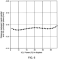
- FIG. 6 depicts the distance between the IOL haptic plane and IOL principal plane ( ⁇ PP ) versus lens power (P) for an IOL 100 having shape factors (X) and anterior/posterior radii of curvature (R 1 /R 2 ) as depicted in FIGS. 3 and 4 respectively.
- FIG. 7 illustrates the power shift resulting from the distance between the IOL haptic plane and IOL principal plane ( ⁇ PP ) plotted in FIG. 6 .
- FIGS. 6-7 illustrate ⁇ PP and corresponding power shift for lenses having shape factors (X) and radii of curvature (R 1 /R 2 ) equal to the curves depicted in FIGS 3-4
- the present disclosure contemplates that, due to the above-described deviation of shape factors (X) and radii of curvature (R 1 /R 2 ) from the curves depicted in FIGS 3-4 resulting from manufacturing constraints or other manufacturing considerations, there may be corresponding deviation from the curves depicted in FIGS. 6-7 .
- the amount of acceptable variation in ⁇ PP between any two lenses of different lens powers (P) may decrease with increased lens power (P).
- the amount of acceptable variation at various lens powers (P) mat be as follows: IOL Power (D) Range of acceptable variation (mm) 6 0.29 10 0.17 20 0.08 30 0.05 34 0.04
- an IOL 100 having the above-described anterior-biased optical design may be less sensitive to misalignment (e.g., decentration and tilt). More particularly, the above-described IOLs 100 have a positive shape factor, meaning they have a relatively high anterior surface curvature.
- the relatively high anterior surface curvature means that light rays incident on and outgoing from the anterior surface have a small average angle from normal directions such that the Gaussian optics formula deviates from Snell's law by a small amount, decreasing sensitivity to decentration.
- IOLs 100 having the above-described anterior-biased optical design may result in better refractive outcomes.
- an IOL 100 having the above-described anterior-biased optical design may reduce the incidence of negative dysphotopsia post-implantation.
- shape factors (X) as depicted in FIG. 3
- R 1 /R 2 anterior/posterior radii of curvature
Landscapes
- Health & Medical Sciences (AREA)
- Ophthalmology & Optometry (AREA)
- Cardiology (AREA)
- Oral & Maxillofacial Surgery (AREA)
- Transplantation (AREA)
- Engineering & Computer Science (AREA)
- Biomedical Technology (AREA)
- Heart & Thoracic Surgery (AREA)
- Vascular Medicine (AREA)
- Life Sciences & Earth Sciences (AREA)
- Animal Behavior & Ethology (AREA)
- General Health & Medical Sciences (AREA)
- Public Health (AREA)
- Veterinary Medicine (AREA)
- Prostheses (AREA)
- Eyeglasses (AREA)
Claims (15)
- Verfahren zum Herstellen einer Intraokularlinse, IOL, die eine Optik mit einer vorderen Oberfläche und einer hinteren Oberfläche umfasst, welche dazu konfiguriert ist, in ein Auge eines Patienten implantiert zu werden, wobei, für jede Linsenbrechkraft (P) in einem Bereich von Linsenbrechkräften von 6 bis 35 Dioptrien, das Verfahren Folgendes umfasst:Auswählen einer Krümmung der vorderen Oberfläche, wobei die vordere Oberfläche einen vorderen Oberflächenkrümmungsradius (R1) und eine vordere Oberflächenbrechkraft (P1) aufweist, wobei die vordere Oberflächenbrechkraft definiert ist als:
 Auswählen einer Krümmung der hinteren Oberfläche, wobei die hintere Oberfläche einen hinteren Oberflächenkrümmungsradius (R2) und eine hintere Oberflächenbrechkraft (P2) aufweist, wobei die hintere Oberflächenbrechkraft definiert ist als:
 n1 ein Brechungsindex von Kammerwasser eines Auges eines Patienten ist;n2 ein Brechungsindex der Optik ist; undAuswählen eines Formfaktors (X), wobei der Formfaktor (X) definiert ist als:
 wobei der Formfaktor (X) größer als null ist und einer Kurve entspricht, die einen Formfaktor (X) als eine Funktion der Linsenbrechkraft (P) definiert, wobei die Kurve mit zunehmender Linsenbrechkraft (P) monoton abnimmt, wobei die Kurve durch die folgende kubische Gleichung definiert ist: X = X 0 + X 1 P + X 2 P 2 + X 3 P 3;wobei X0, X1, X2 und X3 Konstanten mit Werten sind, die reale Zahlen sind.
 - Verfahren nach Anspruch 1, das Definieren der vorderen Oberflächenbrechkraft (P1) als eine Funktion einer Linsenbrechkraft (P) und eines Formfaktors (X) umfasst.
- Verfahren nach Anspruch 1, wobei die Kurve nichtlinear ist.
- Verfahren nach Anspruch 1, wobei der Brechungsindex der Optik in dem Bereich von 1,42 bis 1,56 liegt.
- Verfahren nach Anspruch 1, wobei:X0 in dem Bereich von 0,75 bis 1,5 liegt;X1 eine negative Zahl in dem Bereich von -0,11 bis -0,05 ist;X2 in dem Bereich von 0,0017 bis 0,0035 liegt; undX3 in dem Bereich von -0,000042 bis 0,00002 liegt.
- Verfahren nach Anspruch 1, wobei:
der Formfaktor (X) in dem Bereich von 0,20 bis 1,0 liegt. - Verfahren nach Anspruch 1, das ferner Bereitstellen mehrerer Haptiken umfasst, die sich von einem Rand der Optik erstrecken und eine Haptikebene der ophthalmischen Linse definieren, wobei für alle Linsenbrechkräfte (P) größer als 10 Dioptrien eine Entfernung zwischen einer Hauptebene der Optik und der Haptikebene um einen Betrag kleiner als 0,2 mm variiert.
- Verfahren nach Anspruch 1, das ferner Bereitstellen mehrerer Haptiken umfasst, die sich von einem Rand der Optik erstrecken und eine Haptikebene der ophthalmischen Linse definieren, wobei für jede Linse mit einer Linsenbrechkraft (P) größer als 20 Dioptrien eine Entfernung zwischen einer Hauptebene der Optik und der Haptikebene um einen Betrag kleiner als 0,1 mm variiert.
- Verfahren nach Anspruch 1, wobei:X0 in dem Bereich von 0,75 bis 1,5 liegt;X1 eine negative Zahl in dem Bereich von -0,11 bis -0,05 ist;X2 in dem Bereich von 0,0017 bis 0,0035 liegt; undX3 in dem Bereich von -0,000042 bis 0,00002 liegt;der Formfaktor (X) in dem Bereich von 0,20 bis 1,0 für Linsenbrechkräfte (P) in dem Bereich von 6 bis 35 Dioptrien liegt; undBereitstellen mehrerer Haptiken, die sich von dem Optikrand erstrecken.
- Verfahren nach Anspruch 9, die vordere Oberflächenbrechkraft (P1) eine Funktion einer Linsenbrechkraft (P) und eines Formfaktors (X) ist.
- Verfahren nach Anspruch 4 oder Verfahren nach Anspruch 9, wobei:X0 näherungsweise 1,068 ist;X1 näherungsweise -0,075 ist;X2 näherungsweise 0,0025 ist; undX3 näherungsweise -0,00003 ist.
- Verfahren nach Anspruch 1 oder Verfahren nach Anspruch 9, wobei der Brechungsindex der Optik näherungsweise gleich 1,498 ist.
- Verfahren nach Anspruch 1 oder Verfahren nach Anspruch 9, wobei die vordere Oberfläche eine asphärische Oberfläche ist, und welches ferner Definieren der Pfeilhöhe der asphärischen Oberfläche wie folgt umfasst:
 r eine radiale Entfernung von der optischen Achse ist;c eine Basiskrümmung der vorderen Oberfläche entsprechend dem vorderen Oberflächenkrümmungsradius (R1) ist;k eine konische Konstante ist; unda4 eine Verformungskonstante vierter Ordnung ist; unda6 eine Verformungskonstante sechster Ordnung ist, und wobei k, a4 und a6 so gewählt werden können, dass eine sphärische Zielaberration für eine IOL erzielt wird.
 - Verfahren nach Anspruch 1 oder Anspruch 9, wobei für jede Linse mit einer Linsenbrechkraft (P) größer als 12 Dioptrien der vordere Oberflächenkrümmungsradius (R1) kleiner als 18 mm ist.
- Verfahren nach Anspruch 9, das ferner Bereitstellen der mehreren Haptiken gemäß einem oder mehreren des Folgenden umfasst:(i) wobei die mehreren Haptiken eine Haptikebene der Intraokularlinse definieren; und, für alle Linsenbrechkräfte (P) größer als 10 Dioptrien, eine Entfernung zwischen einer Hauptebene der Optik und der Haptikebene um einen Betrag kleiner als 0,2 mm variiert;(ii) wobei die mehreren Haptiken eine Haptikebene der Intraokularlinse definieren; und, für alle Linsenbrechkräfte (P) größer als 20 Dioptrien, eine Entfernung zwischen einer Hauptebene der Optik und der Haptikebene um einen Betrag kleiner als 0,1 mm variiert.
Applications Claiming Priority (2)
| Application Number | Priority Date | Filing Date | Title |
|---|---|---|---|
| US201762608037P | 2017-12-20 | 2017-12-20 | |
| PCT/IB2018/060467 WO2019123390A2 (en) | 2017-12-20 | 2018-12-20 | Intraocular lenses having an anterior-biased optical design |
Publications (2)
| Publication Number | Publication Date |
|---|---|
| EP3687448A2 EP3687448A2 (de) | 2020-08-05 |
| EP3687448B1 true EP3687448B1 (de) | 2025-03-26 |
Family
ID=65276236
Family Applications (1)
| Application Number | Title | Priority Date | Filing Date |
|---|---|---|---|
| EP18842744.7A Active EP3687448B1 (de) | 2017-12-20 | 2018-12-20 | Intraokularlinsen mit anterior-vorgespanntem optischem design |
Country Status (9)
| Country | Link |
|---|---|
| US (1) | US20190183636A1 (de) |
| EP (1) | EP3687448B1 (de) |
| JP (1) | JP7455744B2 (de) |
| KR (1) | KR102706823B1 (de) |
| CN (1) | CN111511312A (de) |
| AU (1) | AU2018389854C1 (de) |
| CA (1) | CA3081205A1 (de) |
| TW (1) | TW201927262A (de) |
| WO (1) | WO2019123390A2 (de) |
Families Citing this family (4)
| Publication number | Priority date | Publication date | Assignee | Title |
|---|---|---|---|---|
| JP7550760B2 (ja) * | 2018-12-21 | 2024-09-13 | アルコン インコーポレイティド | 眼用レンズ用の多重曲率エッジ |
| JP2023509361A (ja) * | 2019-12-17 | 2023-03-08 | アルコン インコーポレイティド | 光学直径が増した眼内レンズ |
| CA3212291A1 (en) * | 2021-03-09 | 2022-09-15 | Tatvum LLC | Intraocular lens providing extended depth of focus |
| CN116035762A (zh) * | 2023-02-22 | 2023-05-02 | 南开大学 | 一种矫正周边视场像差的人工晶状体 |
Family Cites Families (13)
| Publication number | Priority date | Publication date | Assignee | Title |
|---|---|---|---|---|
| US5290892A (en) | 1990-11-07 | 1994-03-01 | Nestle S.A. | Flexible intraocular lenses made from high refractive index polymers |
| ES2183953T3 (es) | 1995-06-07 | 2003-04-01 | Alcon Lab Inc | Materiales mejorados de lentes oftalmicas de alto indice de refraccion. |
| WO2004090611A2 (en) * | 2003-03-31 | 2004-10-21 | Bausch & Lomb Incorporated | Intraocular lens and method for reducing aberrations in an ocular system |
| EP1771756B1 (de) * | 2004-07-23 | 2015-05-06 | The Regents of The University of California | Metamaterialien |
| EP1753372B1 (de) * | 2005-04-05 | 2009-07-01 | Alcon, Inc. | Verfahren zur gestaltung von linsen für das menschliche auge unter verwendung optimaler formfaktoren |
| US8801781B2 (en) * | 2005-10-26 | 2014-08-12 | Abbott Medical Optics Inc. | Intraocular lens for correcting corneal coma |
| US8974526B2 (en) * | 2007-08-27 | 2015-03-10 | Amo Groningen B.V. | Multizonal lens with extended depth of focus |
| JP4659846B2 (ja) * | 2008-02-14 | 2011-03-30 | 日本電信電話株式会社 | 光信号処理装置 |
| TWI473823B (zh) | 2010-06-21 | 2015-02-21 | Novartis Ag | 具有經降低的閃光之高折射率、丙烯酸系眼科裝置材料 |
| TWI517861B (zh) | 2011-02-08 | 2016-01-21 | 諾華公司 | 低黏度疏水性眼科裝置材料 |
| US9901441B2 (en) * | 2011-08-04 | 2018-02-27 | Graham Barrett | Extended depth of focus intraocular lens and associated methods |
| EP4445870A3 (de) * | 2014-04-21 | 2024-12-25 | Amo Groningen B.V. | Ophthalmische vorrichtungen, system und verfahren zur verbesserung der peripheren sicht |
| AU2017369966A1 (en) * | 2016-11-30 | 2019-06-06 | Amo Groningen B.V. | IOL with reduced pupillary reflections |
-
2018
- 2018-12-17 TW TW107145456A patent/TW201927262A/zh unknown
- 2018-12-20 US US16/227,045 patent/US20190183636A1/en not_active Abandoned
- 2018-12-20 CN CN201880082212.5A patent/CN111511312A/zh active Pending
- 2018-12-20 AU AU2018389854A patent/AU2018389854C1/en active Active
- 2018-12-20 JP JP2020530560A patent/JP7455744B2/ja active Active
- 2018-12-20 CA CA3081205A patent/CA3081205A1/en active Pending
- 2018-12-20 EP EP18842744.7A patent/EP3687448B1/de active Active
- 2018-12-20 WO PCT/IB2018/060467 patent/WO2019123390A2/en not_active Ceased
- 2018-12-20 KR KR1020207016233A patent/KR102706823B1/ko active Active
Also Published As
| Publication number | Publication date |
|---|---|
| KR20200101343A (ko) | 2020-08-27 |
| JP2021507734A (ja) | 2021-02-25 |
| CA3081205A1 (en) | 2019-06-27 |
| KR102706823B1 (ko) | 2024-09-12 |
| RU2020121586A (ru) | 2022-01-20 |
| AU2018389854A1 (en) | 2020-05-14 |
| AU2018389854C1 (en) | 2025-05-01 |
| EP3687448A2 (de) | 2020-08-05 |
| JP7455744B2 (ja) | 2024-03-26 |
| TW201927262A (zh) | 2019-07-16 |
| CN111511312A (zh) | 2020-08-07 |
| RU2020121586A3 (de) | 2022-01-31 |
| WO2019123390A3 (en) | 2019-08-01 |
| WO2019123390A2 (en) | 2019-06-27 |
| BR112020010261A2 (pt) | 2020-11-10 |
| US20190183636A1 (en) | 2019-06-20 |
| AU2018389854B2 (en) | 2024-11-14 |
Similar Documents
| Publication | Publication Date | Title |
|---|---|---|
| EP1785106B1 (de) | Multizonale monofokale Intraokularlinse | |
| US10265162B2 (en) | Multizonal lens with enhanced performance | |
| EP2512372B1 (de) | Ophthalmische linse mit winkeliger veränderlicher phasenverzögerung | |
| EP2611386B1 (de) | Mikroinzisionslinse | |
| US12427011B2 (en) | Intraocular lens platform having improved haptic force distribution | |
| EP3687448B1 (de) | Intraokularlinsen mit anterior-vorgespanntem optischem design | |
| RU2785137C2 (ru) | Интраокулярные линзы, имеющие смещенную вперед оптическую конструкцию | |
| BR112020010261B1 (pt) | Método para fabricar uma lente intraocular |
Legal Events
| Date | Code | Title | Description |
|---|---|---|---|
| STAA | Information on the status of an ep patent application or granted ep patent |
Free format text: STATUS: UNKNOWN |
|
| STAA | Information on the status of an ep patent application or granted ep patent |
Free format text: STATUS: THE INTERNATIONAL PUBLICATION HAS BEEN MADE |
|
| PUAI | Public reference made under article 153(3) epc to a published international application that has entered the european phase |
Free format text: ORIGINAL CODE: 0009012 |
|
| STAA | Information on the status of an ep patent application or granted ep patent |
Free format text: STATUS: REQUEST FOR EXAMINATION WAS MADE |
|
| 17P | Request for examination filed |
Effective date: 20200430 |
|
| AK | Designated contracting states |
Kind code of ref document: A2 Designated state(s): AL AT BE BG CH CY CZ DE DK EE ES FI FR GB GR HR HU IE IS IT LI LT LU LV MC MK MT NL NO PL PT RO RS SE SI SK SM TR |
|
| AX | Request for extension of the european patent |
Extension state: BA ME |
|
| DAV | Request for validation of the european patent (deleted) | ||
| DAX | Request for extension of the european patent (deleted) | ||
| STAA | Information on the status of an ep patent application or granted ep patent |
Free format text: STATUS: EXAMINATION IS IN PROGRESS |
|
| 17Q | First examination report despatched |
Effective date: 20221212 |
|
| P01 | Opt-out of the competence of the unified patent court (upc) registered |
Effective date: 20230507 |
|
| GRAP | Despatch of communication of intention to grant a patent |
Free format text: ORIGINAL CODE: EPIDOSNIGR1 |
|
| STAA | Information on the status of an ep patent application or granted ep patent |
Free format text: STATUS: GRANT OF PATENT IS INTENDED |
|
| INTG | Intention to grant announced |
Effective date: 20241015 |
|
| GRAS | Grant fee paid |
Free format text: ORIGINAL CODE: EPIDOSNIGR3 |
|
| GRAA | (expected) grant |
Free format text: ORIGINAL CODE: 0009210 |
|
| STAA | Information on the status of an ep patent application or granted ep patent |
Free format text: STATUS: THE PATENT HAS BEEN GRANTED |
|
| AK | Designated contracting states |
Kind code of ref document: B1 Designated state(s): AL AT BE BG CH CY CZ DE DK EE ES FI FR GB GR HR HU IE IS IT LI LT LU LV MC MK MT NL NO PL PT RO RS SE SI SK SM TR |
|
| REG | Reference to a national code |
Ref country code: GB Ref legal event code: FG4D |
|
| REG | Reference to a national code |
Ref country code: CH Ref legal event code: EP |
|
| REG | Reference to a national code |
Ref country code: DE Ref legal event code: R096 Ref document number: 602018080540 Country of ref document: DE |
|
| REG | Reference to a national code |
Ref country code: IE Ref legal event code: FG4D |
|
| REG | Reference to a national code |
Ref country code: NL Ref legal event code: FP |
|
| PG25 | Lapsed in a contracting state [announced via postgrant information from national office to epo] |
Ref country code: RS Free format text: LAPSE BECAUSE OF FAILURE TO SUBMIT A TRANSLATION OF THE DESCRIPTION OR TO PAY THE FEE WITHIN THE PRESCRIBED TIME-LIMIT Effective date: 20250626 |
|
| PG25 | Lapsed in a contracting state [announced via postgrant information from national office to epo] |
Ref country code: FI Free format text: LAPSE BECAUSE OF FAILURE TO SUBMIT A TRANSLATION OF THE DESCRIPTION OR TO PAY THE FEE WITHIN THE PRESCRIBED TIME-LIMIT Effective date: 20250326 |
|
| REG | Reference to a national code |
Ref country code: LT Ref legal event code: MG9D |
|
| PG25 | Lapsed in a contracting state [announced via postgrant information from national office to epo] |
Ref country code: NO Free format text: LAPSE BECAUSE OF FAILURE TO SUBMIT A TRANSLATION OF THE DESCRIPTION OR TO PAY THE FEE WITHIN THE PRESCRIBED TIME-LIMIT Effective date: 20250626 |
|
| PG25 | Lapsed in a contracting state [announced via postgrant information from national office to epo] |
Ref country code: HR Free format text: LAPSE BECAUSE OF FAILURE TO SUBMIT A TRANSLATION OF THE DESCRIPTION OR TO PAY THE FEE WITHIN THE PRESCRIBED TIME-LIMIT Effective date: 20250326 |
|
| PG25 | Lapsed in a contracting state [announced via postgrant information from national office to epo] |
Ref country code: LV Free format text: LAPSE BECAUSE OF FAILURE TO SUBMIT A TRANSLATION OF THE DESCRIPTION OR TO PAY THE FEE WITHIN THE PRESCRIBED TIME-LIMIT Effective date: 20250326 |
|
| PG25 | Lapsed in a contracting state [announced via postgrant information from national office to epo] |
Ref country code: GR Free format text: LAPSE BECAUSE OF FAILURE TO SUBMIT A TRANSLATION OF THE DESCRIPTION OR TO PAY THE FEE WITHIN THE PRESCRIBED TIME-LIMIT Effective date: 20250627 Ref country code: BG Free format text: LAPSE BECAUSE OF FAILURE TO SUBMIT A TRANSLATION OF THE DESCRIPTION OR TO PAY THE FEE WITHIN THE PRESCRIBED TIME-LIMIT Effective date: 20250326 |
|
| PG25 | Lapsed in a contracting state [announced via postgrant information from national office to epo] |
Ref country code: SE Free format text: LAPSE BECAUSE OF FAILURE TO SUBMIT A TRANSLATION OF THE DESCRIPTION OR TO PAY THE FEE WITHIN THE PRESCRIBED TIME-LIMIT Effective date: 20250326 |
|
| REG | Reference to a national code |
Ref country code: AT Ref legal event code: MK05 Ref document number: 1778297 Country of ref document: AT Kind code of ref document: T Effective date: 20250326 |
|
| PG25 | Lapsed in a contracting state [announced via postgrant information from national office to epo] |
Ref country code: SM Free format text: LAPSE BECAUSE OF FAILURE TO SUBMIT A TRANSLATION OF THE DESCRIPTION OR TO PAY THE FEE WITHIN THE PRESCRIBED TIME-LIMIT Effective date: 20250326 |
|
| PG25 | Lapsed in a contracting state [announced via postgrant information from national office to epo] |
Ref country code: PT Free format text: LAPSE BECAUSE OF FAILURE TO SUBMIT A TRANSLATION OF THE DESCRIPTION OR TO PAY THE FEE WITHIN THE PRESCRIBED TIME-LIMIT Effective date: 20250728 Ref country code: ES Free format text: LAPSE BECAUSE OF FAILURE TO SUBMIT A TRANSLATION OF THE DESCRIPTION OR TO PAY THE FEE WITHIN THE PRESCRIBED TIME-LIMIT Effective date: 20250326 |
|
| PG25 | Lapsed in a contracting state [announced via postgrant information from national office to epo] |
Ref country code: PL Free format text: LAPSE BECAUSE OF FAILURE TO SUBMIT A TRANSLATION OF THE DESCRIPTION OR TO PAY THE FEE WITHIN THE PRESCRIBED TIME-LIMIT Effective date: 20250326 Ref country code: IT Free format text: LAPSE BECAUSE OF FAILURE TO SUBMIT A TRANSLATION OF THE DESCRIPTION OR TO PAY THE FEE WITHIN THE PRESCRIBED TIME-LIMIT Effective date: 20250326 |
|
| PG25 | Lapsed in a contracting state [announced via postgrant information from national office to epo] |
Ref country code: AT Free format text: LAPSE BECAUSE OF FAILURE TO SUBMIT A TRANSLATION OF THE DESCRIPTION OR TO PAY THE FEE WITHIN THE PRESCRIBED TIME-LIMIT Effective date: 20250326 |
|
| PG25 | Lapsed in a contracting state [announced via postgrant information from national office to epo] |
Ref country code: EE Free format text: LAPSE BECAUSE OF FAILURE TO SUBMIT A TRANSLATION OF THE DESCRIPTION OR TO PAY THE FEE WITHIN THE PRESCRIBED TIME-LIMIT Effective date: 20250326 |
|
| PG25 | Lapsed in a contracting state [announced via postgrant information from national office to epo] |
Ref country code: RO Free format text: LAPSE BECAUSE OF FAILURE TO SUBMIT A TRANSLATION OF THE DESCRIPTION OR TO PAY THE FEE WITHIN THE PRESCRIBED TIME-LIMIT Effective date: 20250326 |
|
| PG25 | Lapsed in a contracting state [announced via postgrant information from national office to epo] |
Ref country code: SK Free format text: LAPSE BECAUSE OF FAILURE TO SUBMIT A TRANSLATION OF THE DESCRIPTION OR TO PAY THE FEE WITHIN THE PRESCRIBED TIME-LIMIT Effective date: 20250326 |
|
| PG25 | Lapsed in a contracting state [announced via postgrant information from national office to epo] |
Ref country code: IS Free format text: LAPSE BECAUSE OF FAILURE TO SUBMIT A TRANSLATION OF THE DESCRIPTION OR TO PAY THE FEE WITHIN THE PRESCRIBED TIME-LIMIT Effective date: 20250726 |
|
| PGFP | Annual fee paid to national office [announced via postgrant information from national office to epo] |
Ref country code: NL Payment date: 20251126 Year of fee payment: 8 |
|
| PGFP | Annual fee paid to national office [announced via postgrant information from national office to epo] |
Ref country code: DE Payment date: 20251119 Year of fee payment: 8 |
|
| PGFP | Annual fee paid to national office [announced via postgrant information from national office to epo] |
Ref country code: GB Payment date: 20251120 Year of fee payment: 8 |
|
| PG25 | Lapsed in a contracting state [announced via postgrant information from national office to epo] |
Ref country code: DK Free format text: LAPSE BECAUSE OF FAILURE TO SUBMIT A TRANSLATION OF THE DESCRIPTION OR TO PAY THE FEE WITHIN THE PRESCRIBED TIME-LIMIT Effective date: 20250326 |
|
| PGFP | Annual fee paid to national office [announced via postgrant information from national office to epo] |
Ref country code: FR Payment date: 20251124 Year of fee payment: 8 |
|
| PG25 | Lapsed in a contracting state [announced via postgrant information from national office to epo] |
Ref country code: CZ Free format text: LAPSE BECAUSE OF FAILURE TO SUBMIT A TRANSLATION OF THE DESCRIPTION OR TO PAY THE FEE WITHIN THE PRESCRIBED TIME-LIMIT Effective date: 20250326 |
|
| PGFP | Annual fee paid to national office [announced via postgrant information from national office to epo] |
Ref country code: IE Payment date: 20251126 Year of fee payment: 8 |
|
| PLBE | No opposition filed within time limit |
Free format text: ORIGINAL CODE: 0009261 |
|
| STAA | Information on the status of an ep patent application or granted ep patent |
Free format text: STATUS: NO OPPOSITION FILED WITHIN TIME LIMIT |
|
| REG | Reference to a national code |
Ref country code: CH Ref legal event code: L10 Free format text: ST27 STATUS EVENT CODE: U-0-0-L10-L00 (AS PROVIDED BY THE NATIONAL OFFICE) Effective date: 20260211 |