EP3686545A1 - Caseless weapon (variants) - Google Patents
Caseless weapon (variants) Download PDFInfo
- Publication number
- EP3686545A1 EP3686545A1 EP17925445.3A EP17925445A EP3686545A1 EP 3686545 A1 EP3686545 A1 EP 3686545A1 EP 17925445 A EP17925445 A EP 17925445A EP 3686545 A1 EP3686545 A1 EP 3686545A1
- Authority
- EP
- European Patent Office
- Prior art keywords
- disposed
- hole
- protrusion
- spring
- cylindrical
- Prior art date
- Legal status (The legal status is an assumption and is not a legal conclusion. Google has not performed a legal analysis and makes no representation as to the accuracy of the status listed.)
- Pending
Links
- 238000009527 percussion Methods 0.000 claims abstract description 184
- MFOUDYKPLGXPGO-UHFFFAOYSA-N propachlor Chemical compound ClCC(=O)N(C(C)C)C1=CC=CC=C1 MFOUDYKPLGXPGO-UHFFFAOYSA-N 0.000 claims abstract description 166
- 238000010304 firing Methods 0.000 claims abstract description 118
- 230000007246 mechanism Effects 0.000 claims abstract description 118
- 230000003993 interaction Effects 0.000 claims description 60
- 230000001154 acute effect Effects 0.000 claims description 22
- 238000009423 ventilation Methods 0.000 claims description 18
- 239000011819 refractory material Substances 0.000 claims description 6
- 230000007704 transition Effects 0.000 claims description 4
- 239000007789 gas Substances 0.000 description 59
- 239000012634 fragment Substances 0.000 description 25
- 239000003380 propellant Substances 0.000 description 25
- 238000000034 method Methods 0.000 description 17
- 230000008569 process Effects 0.000 description 17
- 239000007788 liquid Substances 0.000 description 12
- 230000014759 maintenance of location Effects 0.000 description 12
- 239000007787 solid Substances 0.000 description 12
- 238000009434 installation Methods 0.000 description 11
- 230000009471 action Effects 0.000 description 10
- 230000006870 function Effects 0.000 description 8
- 230000001934 delay Effects 0.000 description 7
- 239000004576 sand Substances 0.000 description 7
- XLYOFNOQVPJJNP-UHFFFAOYSA-N water Substances O XLYOFNOQVPJJNP-UHFFFAOYSA-N 0.000 description 7
- 102220498641 Protein LRATD2_F41A_mutation Human genes 0.000 description 6
- 239000000428 dust Substances 0.000 description 6
- 239000000843 powder Substances 0.000 description 6
- 230000002441 reversible effect Effects 0.000 description 5
- 230000008859 change Effects 0.000 description 4
- 238000005096 rolling process Methods 0.000 description 4
- 230000000903 blocking effect Effects 0.000 description 3
- 238000006073 displacement reaction Methods 0.000 description 3
- 230000008030 elimination Effects 0.000 description 3
- 238000003379 elimination reaction Methods 0.000 description 3
- 230000007774 longterm Effects 0.000 description 3
- 239000000463 material Substances 0.000 description 3
- 238000003825 pressing Methods 0.000 description 3
- 230000008439 repair process Effects 0.000 description 3
- 230000004075 alteration Effects 0.000 description 2
- 238000006243 chemical reaction Methods 0.000 description 2
- 238000001816 cooling Methods 0.000 description 2
- -1 dirt Substances 0.000 description 2
- 230000000694 effects Effects 0.000 description 2
- 238000010438 heat treatment Methods 0.000 description 2
- 210000003127 knee Anatomy 0.000 description 2
- 239000002245 particle Substances 0.000 description 2
- 230000009467 reduction Effects 0.000 description 2
- 238000009825 accumulation Methods 0.000 description 1
- 230000000712 assembly Effects 0.000 description 1
- 238000000429 assembly Methods 0.000 description 1
- 102220353721 c.122T>G Human genes 0.000 description 1
- 239000002775 capsule Substances 0.000 description 1
- 238000011109 contamination Methods 0.000 description 1
- 238000005520 cutting process Methods 0.000 description 1
- 230000006378 damage Effects 0.000 description 1
- 230000004907 flux Effects 0.000 description 1
- 230000006872 improvement Effects 0.000 description 1
- 238000005304 joining Methods 0.000 description 1
- 239000011499 joint compound Substances 0.000 description 1
- 239000002184 metal Substances 0.000 description 1
- 238000005498 polishing Methods 0.000 description 1
- 230000004044 response Effects 0.000 description 1
- 230000000284 resting effect Effects 0.000 description 1
- 230000009834 selective interaction Effects 0.000 description 1
- 230000002269 spontaneous effect Effects 0.000 description 1
- 230000006641 stabilisation Effects 0.000 description 1
- 238000011105 stabilization Methods 0.000 description 1
- 230000003068 static effect Effects 0.000 description 1
- 238000003860 storage Methods 0.000 description 1
- 210000003813 thumb Anatomy 0.000 description 1
Images


Classifications
-
- F—MECHANICAL ENGINEERING; LIGHTING; HEATING; WEAPONS; BLASTING
- F41—WEAPONS
- F41A—FUNCTIONAL FEATURES OR DETAILS COMMON TO BOTH SMALLARMS AND ORDNANCE, e.g. CANNONS; MOUNTINGS FOR SMALLARMS OR ORDNANCE
- F41A3/00—Breech mechanisms, e.g. locks
- F41A3/12—Bolt action, i.e. the main breech opening movement being parallel to the barrel axis
- F41A3/14—Rigid bolt locks, i.e. having locking elements rigidly mounted on the bolt or bolt handle and on the barrel or breech-housing respectively
- F41A3/16—Rigid bolt locks, i.e. having locking elements rigidly mounted on the bolt or bolt handle and on the barrel or breech-housing respectively the locking elements effecting a rotary movement about the barrel axis, e.g. rotating cylinder bolt locks
- F41A3/18—Rigid bolt locks, i.e. having locking elements rigidly mounted on the bolt or bolt handle and on the barrel or breech-housing respectively the locking elements effecting a rotary movement about the barrel axis, e.g. rotating cylinder bolt locks hand-operated
- F41A3/20—Straight-pull operated bolt locks, i.e. the operating hand effecting only a straight movement parallel to the barrel axis
-
- F—MECHANICAL ENGINEERING; LIGHTING; HEATING; WEAPONS; BLASTING
- F41—WEAPONS
- F41A—FUNCTIONAL FEATURES OR DETAILS COMMON TO BOTH SMALLARMS AND ORDNANCE, e.g. CANNONS; MOUNTINGS FOR SMALLARMS OR ORDNANCE
- F41A3/00—Breech mechanisms, e.g. locks
- F41A3/64—Mounting of breech-blocks; Accessories for breech-blocks or breech-block mountings
- F41A3/66—Breech housings or frames; Receivers
-
- F—MECHANICAL ENGINEERING; LIGHTING; HEATING; WEAPONS; BLASTING
- F41—WEAPONS
- F41A—FUNCTIONAL FEATURES OR DETAILS COMMON TO BOTH SMALLARMS AND ORDNANCE, e.g. CANNONS; MOUNTINGS FOR SMALLARMS OR ORDNANCE
- F41A11/00—Assembly or disassembly features; Modular concepts; Articulated or collapsible guns
-
- F—MECHANICAL ENGINEERING; LIGHTING; HEATING; WEAPONS; BLASTING
- F41—WEAPONS
- F41A—FUNCTIONAL FEATURES OR DETAILS COMMON TO BOTH SMALLARMS AND ORDNANCE, e.g. CANNONS; MOUNTINGS FOR SMALLARMS OR ORDNANCE
- F41A15/00—Cartridge extractors, i.e. devices for pulling cartridges or cartridge cases at least partially out of the cartridge chamber; Cartridge ejectors, i.e. devices for throwing the extracted cartridges or cartridge cases free of the gun
- F41A15/12—Cartridge extractors, i.e. devices for pulling cartridges or cartridge cases at least partially out of the cartridge chamber; Cartridge ejectors, i.e. devices for throwing the extracted cartridges or cartridge cases free of the gun for bolt-action guns
- F41A15/16—Cartridge extractors, i.e. devices for pulling cartridges or cartridge cases at least partially out of the cartridge chamber; Cartridge ejectors, i.e. devices for throwing the extracted cartridges or cartridge cases free of the gun for bolt-action guns the ejector being mounted on the breech housing or frame
-
- F—MECHANICAL ENGINEERING; LIGHTING; HEATING; WEAPONS; BLASTING
- F41—WEAPONS
- F41A—FUNCTIONAL FEATURES OR DETAILS COMMON TO BOTH SMALLARMS AND ORDNANCE, e.g. CANNONS; MOUNTINGS FOR SMALLARMS OR ORDNANCE
- F41A15/00—Cartridge extractors, i.e. devices for pulling cartridges or cartridge cases at least partially out of the cartridge chamber; Cartridge ejectors, i.e. devices for throwing the extracted cartridges or cartridge cases free of the gun
- F41A15/20—Cartridge extractors, i.e. devices for pulling cartridges or cartridge cases at least partially out of the cartridge chamber; Cartridge ejectors, i.e. devices for throwing the extracted cartridges or cartridge cases free of the gun specially adapted for caseless-ammunition duds
-
- F—MECHANICAL ENGINEERING; LIGHTING; HEATING; WEAPONS; BLASTING
- F41—WEAPONS
- F41A—FUNCTIONAL FEATURES OR DETAILS COMMON TO BOTH SMALLARMS AND ORDNANCE, e.g. CANNONS; MOUNTINGS FOR SMALLARMS OR ORDNANCE
- F41A17/00—Safety arrangements, e.g. safeties
- F41A17/46—Trigger safeties, i.e. means for preventing trigger movement
-
- F—MECHANICAL ENGINEERING; LIGHTING; HEATING; WEAPONS; BLASTING
- F41—WEAPONS
- F41A—FUNCTIONAL FEATURES OR DETAILS COMMON TO BOTH SMALLARMS AND ORDNANCE, e.g. CANNONS; MOUNTINGS FOR SMALLARMS OR ORDNANCE
- F41A19/00—Firing or trigger mechanisms; Cocking mechanisms
- F41A19/06—Mechanical firing mechanisms, e.g. counterrecoil firing, recoil actuated firing mechanisms
- F41A19/16—Adjustable firing mechanisms; Trigger mechanisms with adjustable trigger pull
-
- F—MECHANICAL ENGINEERING; LIGHTING; HEATING; WEAPONS; BLASTING
- F41—WEAPONS
- F41A—FUNCTIONAL FEATURES OR DETAILS COMMON TO BOTH SMALLARMS AND ORDNANCE, e.g. CANNONS; MOUNTINGS FOR SMALLARMS OR ORDNANCE
- F41A19/00—Firing or trigger mechanisms; Cocking mechanisms
- F41A19/06—Mechanical firing mechanisms, e.g. counterrecoil firing, recoil actuated firing mechanisms
- F41A19/42—Mechanical firing mechanisms, e.g. counterrecoil firing, recoil actuated firing mechanisms having at least one hammer
- F41A19/43—Mechanical firing mechanisms, e.g. counterrecoil firing, recoil actuated firing mechanisms having at least one hammer in bolt-action guns
-
- F—MECHANICAL ENGINEERING; LIGHTING; HEATING; WEAPONS; BLASTING
- F41—WEAPONS
- F41A—FUNCTIONAL FEATURES OR DETAILS COMMON TO BOTH SMALLARMS AND ORDNANCE, e.g. CANNONS; MOUNTINGS FOR SMALLARMS OR ORDNANCE
- F41A21/00—Barrels; Gun tubes; Muzzle attachments; Barrel mounting means
- F41A21/12—Cartridge chambers; Chamber liners
-
- F—MECHANICAL ENGINEERING; LIGHTING; HEATING; WEAPONS; BLASTING
- F41—WEAPONS
- F41A—FUNCTIONAL FEATURES OR DETAILS COMMON TO BOTH SMALLARMS AND ORDNANCE, e.g. CANNONS; MOUNTINGS FOR SMALLARMS OR ORDNANCE
- F41A21/00—Barrels; Gun tubes; Muzzle attachments; Barrel mounting means
- F41A21/32—Muzzle attachments or glands
- F41A21/36—Muzzle attachments or glands for recoil reduction ; Stabilisators; Compensators, e.g. for muzzle climb prevention
-
- F—MECHANICAL ENGINEERING; LIGHTING; HEATING; WEAPONS; BLASTING
- F41—WEAPONS
- F41A—FUNCTIONAL FEATURES OR DETAILS COMMON TO BOTH SMALLARMS AND ORDNANCE, e.g. CANNONS; MOUNTINGS FOR SMALLARMS OR ORDNANCE
- F41A3/00—Breech mechanisms, e.g. locks
- F41A3/12—Bolt action, i.e. the main breech opening movement being parallel to the barrel axis
- F41A3/14—Rigid bolt locks, i.e. having locking elements rigidly mounted on the bolt or bolt handle and on the barrel or breech-housing respectively
- F41A3/16—Rigid bolt locks, i.e. having locking elements rigidly mounted on the bolt or bolt handle and on the barrel or breech-housing respectively the locking elements effecting a rotary movement about the barrel axis, e.g. rotating cylinder bolt locks
- F41A3/26—Rigid bolt locks, i.e. having locking elements rigidly mounted on the bolt or bolt handle and on the barrel or breech-housing respectively the locking elements effecting a rotary movement about the barrel axis, e.g. rotating cylinder bolt locks semi-automatically or automatically operated, e.g. having a slidable bolt-carrier and a rotatable bolt
-
- F—MECHANICAL ENGINEERING; LIGHTING; HEATING; WEAPONS; BLASTING
- F41—WEAPONS
- F41C—SMALLARMS, e.g. PISTOLS, RIFLES; ACCESSORIES THEREFOR
- F41C23/00—Butts; Butt plates; Stocks
- F41C23/14—Adjustable stock or stock parts, i.e. adaptable to personal requirements, e.g. length, pitch, cast or drop
-
- F—MECHANICAL ENGINEERING; LIGHTING; HEATING; WEAPONS; BLASTING
- F41—WEAPONS
- F41C—SMALLARMS, e.g. PISTOLS, RIFLES; ACCESSORIES THEREFOR
- F41C23/00—Butts; Butt plates; Stocks
- F41C23/16—Forestocks; Handgrips; Hand guards
-
- F—MECHANICAL ENGINEERING; LIGHTING; HEATING; WEAPONS; BLASTING
- F41—WEAPONS
- F41C—SMALLARMS, e.g. PISTOLS, RIFLES; ACCESSORIES THEREFOR
- F41C7/00—Shoulder-fired smallarms, e.g. rifles, carbines, shotguns
-
- F—MECHANICAL ENGINEERING; LIGHTING; HEATING; WEAPONS; BLASTING
- F41—WEAPONS
- F41G—WEAPON SIGHTS; AIMING
- F41G1/00—Sighting devices
- F41G1/30—Reflecting-sights specially adapted for smallarms or ordnance
-
- F—MECHANICAL ENGINEERING; LIGHTING; HEATING; WEAPONS; BLASTING
- F42—AMMUNITION; BLASTING
- F42B—EXPLOSIVE CHARGES, e.g. FOR BLASTING, FIREWORKS, AMMUNITION
- F42B5/00—Cartridge ammunition, e.g. separately-loaded propellant charges
- F42B5/02—Cartridges, i.e. cases with charge and missile
- F42B5/10—Cartridges, i.e. cases with charge and missile with self-propelled bullet
-
- F—MECHANICAL ENGINEERING; LIGHTING; HEATING; WEAPONS; BLASTING
- F42—AMMUNITION; BLASTING
- F42B—EXPLOSIVE CHARGES, e.g. FOR BLASTING, FIREWORKS, AMMUNITION
- F42B5/00—Cartridge ammunition, e.g. separately-loaded propellant charges
- F42B5/02—Cartridges, i.e. cases with charge and missile
- F42B5/18—Caseless ammunition; Cartridges having combustible cases
Definitions
- Some functions of the claimed invention were used in previous firearms designs, more particularly, for example, weapons of Garand and Tokarev with a piston striker and a movable capsule.
- the weapon is divided into the next types: a pistol, a machine gun, an assault rifle, a light machine gun, an average machine gun, each with its ammunition, and each type of weapon has its optimal principles of automation, design of assemblies and mechanisms. Further reduction of the size and weight, an increase of the weapon power, the acquisition of new properties are possible only with the use of a new designs.
- the buffer fear is located in the inner cavity of the pistol grip, it contains a two-arm buffer lever, one arm of which is located on the displacement of the lock frame, and the second has the possibility to interact with a spring-loaded buffer installed in the body;
- the switch knob is a rod, ledges are made on the rod with the possibility of selective interaction with the response slots of different depths made in housing buffer, and in the lower part of the bolt is fixed on the axis of the spring-loaded rammer with the ability to rotate its working part, in the direction towards the cartridge in the store.
- the disadvantages of this invention are: the unhandiness, complexity of the embodiment with the abundance of rotating and moving parts, which consists of a large number of complex-shaped parts.
- a fighter with a weapon In combat conditions, a fighter with a weapon is often being situated in mud, dust, water, sand, which leads to contamination of ammunition, and if there is no forced supply of ammunition, there is a delay in shooting, which threatens the death of a fighter.
- the weapon should be configured with a forced supply of ammunition.
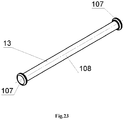
- the rod (13) is configured with the washer with the radial chamfer (107), which passes into cylindrical part (108), which passes into the washer with the radial chamfer (107).
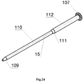
- the guide rod (15) is configured with the spherical head (109), which passes into cylindrical part (110), which via a conical transition (111) passes into cylindrical part (112) with bigger diameter, which passes into the washer with radial chamfer (107).
- the forward grip (4) comprising a body (351) in which a threaded cover (352) and a retainer spring-loaded with a spring of a locking pin (356) are mounted, and configured in the form of a locking pin (353), which is mounted in the body (351), and at the end of the locking pin (353) coming out of the body (351), a locking pin head (354) is mounted, which is fixed with a splint pin of the locking pin (355).
- the caseless semi-automatic weapon (1B) is additionally equipped with a bayonet-knife (427), which contains a front stop with a ring (428), a handle (431) with a slot (430) and a back stop with hook-shaped protrusion (429).
- a bayonet-knife (427) which contains a front stop with a ring (428), a handle (431) with a slot (430) and a back stop with hook-shaped protrusion (429).
- the caseless automatic weapon (1C) is additionally equipped with a bayonet-knife (427), which contains a front stop with a ring (428), a handle (431) with a slot (430) and a back stop with hook-shaped protrusion (429).
- a bayonet-knife (427) which contains a front stop with a ring (428), a handle (431) with a slot (430) and a back stop with hook-shaped protrusion (429).
- the multifunction switch increases the efficiency and accuracy of shooting.
- a container is arranged in the front handle, and the front handle body having two L-shaped ledges with a triangular groove for the wrench for removing or installing the flame arrester compensator and the barrel in field conditions, which has bigger functionality by having the front handle.
- Another claimed feature of the proposed weapon is the possibility to disassemble the magazine, semiautomatic and automatic caseless weapons to pieces to the factory level and then assemble it without any special tools in any conditions.
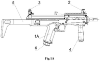
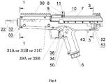
- Figure 4 show a side view of the weapon for magazine shot 1A
- Figure 6A is a longitudinal section of the weapon 1A
- Figure 7 is a fragment of a longitudinal section of the weapon 1A on the pusher of the magazine latch 35
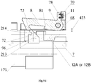
- Figure 8 is a cross-section 1-1 on Figure 4
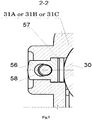
- Figure 9 is a cross-section 2-2 on Figure 5
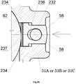
- Figure 13 is a cross-section 3-3 on Figure 4 of the weapon 1A.
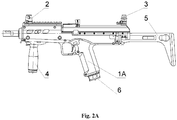
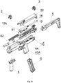
- Figure 15 is a disassembly of the semi-automatic weapon 1B on units (side view). Units comprising: the removable front sight 2, the removable dioptrical sight 3, the forward grip 4, the gunstock 5, the magazine 6, the cover of the receiver with mechanisms 60, the bolt carrier 12A with the bolt 61, the guide rod of a returnable spring 15, the returnable spring 16, the receiver with barrel and mechanisms 62, the trigger housing with mechanisms 63B, the multifunction latch 64.
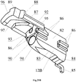
- Figure 20A is a front view of the bolt carrier 12A
- Figure 21A is a fragment of the rear part of the bolt carrier 12A
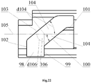
- Figure 22 is a bottom view on the cam slot 96 of the bolt carrier 12A or 12B.
- the bolt carrier 12A comprises the bar 82, the lower part of which has the form of the trapezoidal section 83.
- Enlargement 84 disposed in the rear part of the trapezoidal section 83.
- the guided ledges 86 disposed on the side surface of the bar 82, wherein said guided ledges 86 are configured to interact with the channel guide 178 of the receiver 30.
- the front upper part of the bar 82 shaped in the form of console 87.
- Figure 23 is a side view of the rod 13.
- the rod 13 has the washer with the radial chamfer 107, which passes into the cylindrical part 108, which passes into the washer with the radial chamfer 107.
- Said rod is element of the weapon 1A.
- Figure 23 showing all elements of the rod 13, their forms and interactions.
- Figure 24 is a side view of the guide rod 15.
- the guide rod 15 configured in the form of the spherical head 109, which passes into the cylindrical part 110, which via the conical transition 111 passes into the cylindrical part 112 with bigger diameter, which passes into the washer with the radial chamfer 107.
- Said guide rod is an element of the weapon 1B and 1C. Figure 24 showing all elements of the guide rod 15, their forms and interactions.
- Figure 25 is a side view of the bolt 61 and Figure 26 is a longitudinal section of the bolt 61.
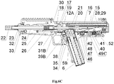
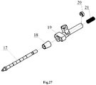
- the bolt 61 comprising: the percussion piston 17, the conical bushing of the bolt 18, shutter housing 19, the safety catch of the firing percussion 20, the spring of the firing percussion 21.
- Figure 27 is a detailing of the bolt 61 (side view). This configuration comprising: the percussion piston 17, the conical bushing of the bolt 18, shutter housing 19, the safety catch of the firing percussion 20, the spring of the firing percussion 21.
- Figure 29 is a side view of the percussion piston 17.
- the percussion piston 17 configured in stepped shaft form.
- the conical section 118 which passes into the cylindrical section with smaller diameter 119 disposed forepart, wherein the inclined ledge 120 disposed at the joint of the conical section 118 and the cylindrical section with smaller diameter 119.
- An angle of the ledge incline d120 to axis of the firing percussion 121 correlates to 30-45 degrees, which is optimal value to ensure peeling force of the ammunition 59 with the threaded bushing 166 of the multifunctional cartridge 26.
- the cylindrical section with smaller diameter 119 passes into the cylindrical section with bigger diameter 122, which passes into the cylindrical piston 123.
- the cylindrical piston 123 passes into the rod section with the grooves 124, wherein the rear groove configured for the safety catch of the firing percussion 20.
- Figure 29 showing all elements of the firing percussion 17, their forms and interactions.
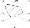
- the stepped ledge is disposed therein, which comprising the base 131 and the leading ledge 132, configured to interact with the cam slot 97 of the bolt carrier 12A or 12B.
- the leading ledge 132 has rear leading edge 133, side edge of the free running 134 and 135, rear radius chamfers 136, the external sideway forepart scarf 137 and the external radius section 138.
- Two cylindrical grooves with inclined sides 139 disposed on the base 131.
- the base 131 is disposed at angle to the locking lug 129.
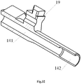
- the glazed area 140 for the conical bushing on the bolt 18 disposed at the end of the cylindrical head 127.
- the central cylindrical channel 141 for the percussion piston 17 disposed within the shutter housing 19.
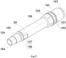
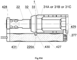
- Figure 34 is a detailing of the receiver with the barrel and mechanisms 62 (side view). This configuration comprising: the balancing gear 22, the spring washer of the balancing gear 23, the barrel 24 with smooth channel, the barrel latch 25, multifunctional cartridge 26, the conical bushing of the receiver 27, the extractor 28, the lock washer of the extractor 29, the receiver 30.
- Figure 36 is a front view of the spring washer of the balancing gear 23.
- the spring washer of the balancing gear 23 configured as the split ring 151 and the three-sided flange 152 on the internal side.
- the spring washer of the balancing gear 23 with their three-sided flange 152 abuts against threaded section 155 for balancing gear 23 when the balancing gear 23 is removed from barrel 24, which allows the balancing gear 23 to not be lost.
- the ends of the split ring 151 have a bias 153.
- the measure of bias T153 correlates 0.2D23, where D23 - is the outer diameter of the spring washer of the balancing gear 23. Said measure is optimal for performing a spring clamp function.
- Figure 36 showing all elements of the spring washer of the balancing gear 23, their forms and interactions.
- Figure 38 is a longitudinal section of the multifunctional cartridge 26.
- the multifunctional cartridge 26 comprising the threaded bushing 165, the internal smooth bushing 166, at least one middle bushing 167 and the external bushing with variable diameter 168, which has bigger diameter 169.
- the threaded bushing 165 and the inner smooth bushing 166 are made of carbide and refractory material.
- the threaded bushing 165 made of carbide and refractory material and has two or more threaded grooves. The pitchs and forms of grooves depends on applying ammunition.
- the bushings 165, 166, 167 and 168 are inserted into each other with tension and created the multifunctional cartridge 26. Outer surface of the bushings 165, 166, 167 and 168 are highly polished.
- the multifunctional cartridge 26 provide high pressure during firing, and high polishing ensures minimal heat loss in the hottest part.
- the polished surface reflecting the heat flux as a thermos.
- the carbide and refractory threaded groove 165, the inner smooth bushing 166 provide high reliability of the weapon during the high temperature of gases produced when the propellant is burnt.
- Figure 38 showing all elements of the spring washer of the multifunctional cartridge 26, their forms and interactions.
- the lower part of the receiver 181 configured in the form of a box-section figure, wherein the cam hole 183 for passage the cocking piece 49A or 49B and the magazine 6 is disposed on the bottom of lower part of the receiver 181.
- the channel guides 178 are fastened to the lower part of the receiver 181 and the barrel chamber 173 via the cap screws 184.
- the stop 185 for the trigger box 31A or 31B or 31C disposed on the rear part of lower part of the receiver 181.
- the stop 185 has the cross through hole 186, which configured to interact with the multifunction latch 64 and two vertical threaded holes 187, wherein said stop is mounted on the rear part of the receiver 181 below via screws 188.
- the rear swivel 189 is disposed on the stop 185.
- the receiver 30 also comprising the bracket 190 having the threaded holes 191 in the lower part for fastening the bracket 190 to the lower part of the receiver 181 and a longitudinal hole 193, which configured to interact with a ramrod 58.
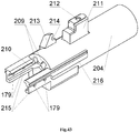
- FIG 43 is a side view of the barrel chamber 173 and Figure 44 is a longitudinal section of the barrel chamber 173.
- the barrel chamber 173 has a cylindrical part 204.
- a multistage cylindrical hole with a threaded section 205 is disposed, which configured to mounting the conical bushing of the receiver 27, to mounting the multifunctional cartridge 26 and to mounting the barrel 24.
- the cross threaded hole 206 is the inlet of the multistage cylindrical hole 205 with threaded section.
- the multistage cylindrical hole with threaded section 205 passes into the cylindrical groove 207, the lower part of which has a threaded hole 208 for the locking screw of the barrel chamber 174.
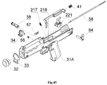
- Figure 47 is a detailing of the trigger housing with mechanisms 63C for automatic weapon 1C.
- the trigger housing with mechanisms 63C comprising: the trigger housing 31C, the big front screw 32, the front swivel 33, the magazine the latch 34, the safety catch 38, the trigger bar spring 41, the slide stop 50, the slide stop spring 51, the latch of ramrod 56, the spring of the latch of ramrod 57, the ramrod 58, the multifunction latch 64, the retainer mechanism 217, the firing mechanism for automatic shot 220, the percussion mechanism 222 for semi-automatic and automatic shot.
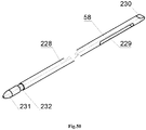
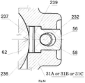
- Figure 51 is a side view of the latch of ramrod 56.
- the latch of ramrod 56 is configured in the form of a plate 233 with rounded ledges 234 on the lower part.
- the through semicircular hole 235 is disposed in the center of the plate 233.
- the semicircular slot 236 is disposed in the lower part of the through hole 235.
- Figure 51 showing all elements of the latch of ramrod 56, their forms and interactions.
- Figure 57A is a side view of the trigger housing 31A.
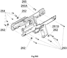
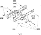
- the trigger housing 31A comprising: the right half of the trigger housing 260A and left half of the trigger housing 261A, lower ventilation bushings 262, which additionally function as the hinge for installation a trunnion for a tripod, that provid a precision shoot from a fixed position, cap screws 263, threaded bushings 264 for cap screws 263, threaded bushing with the splineway 265 for cap screw 263 in the gunstock 5 installation place.
- Figure 57B is a side view of the trigger housing 31B.
- the trigger housing 31B comprising: the right half of the trigger housing 260A and left half of the trigger housing 261B, lower ventilation bushings 262, which additionally function as the hinge for installation a trunnion for a tripod, that provid a precision shoot from a fixed position, cap screws 263, threaded bushings 264 for cap screws 263, threaded bushing with the splineway 265 for cap screw 263 in the gunstock 5 installation place.
- Figure 58A is a detailing of the trigger housing 31A (side view). This configuration comprising: the right half of the trigger housing 260A and left half of the trigger housing 261A, lower ventilation bushings 262, cap screws 263, threaded bushings 264, threaded bushing with the splineway 265.
- Figure 58B is a detailing of the trigger housing 31B (side view). This configuration comprising: the right half of the trigger housing 260A and left half of the trigger housing 261B, lower ventilation bushings 262, cap screws 263, threaded bushings 264, threaded bushing with the splineway 265.
- Figure 58C is a detailing of the trigger housing 31C side view). This configuration comprising: the right half of the trigger housing 260C and left half of the trigger housing 261B, lower ventilation bushings 262, cap screws 263, threaded bushings 264, threaded bushing with the splineway 265.
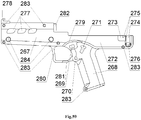
- Figure 59 is a side view of the outside of the left half of the trigger housing 261A or 261B
- Figure 60 is a side view of the inside of the left half of the trigger housing 261A or 261B.
- the threaded hole 266 for the big front nut 32 and the handguard 267 are disposed in the front part of the left half of the trigger housing 261A or 261B.
- the left half of the trigger housing 261A or 261B having the pistol grip 268 below in the middle.
- the rectangular hole 269 for the safety catch 38 and hole 270 for the magazine latch 34 are disposed in the pistol grip 268.
- the "T" shaped hole 271 for the slide stop 50 (only for the left half of the trigger housing 261B) is disposed on the pistol grip 268 .
- Slots 273, 274, which biasing with the inclined area 275 and complex-shaped hole 276 for the multifunction latch 64 are disposed in the rear part of the left half of the trigger housing 261A or 261B.
- Ventilative holes 277 and hook 278 for retention the front sight Picatinny-type rail 199 are disposed on the upper front part of the left half of the trigger housing 261A or 261B.
- the trigger guard 279 is disposed above the pistol grip 268 for the safety catch 38 protection, for the case of the weapon dropping.
- the pistol grip 268 and handguard 267 are fastened via the trigger guard 280, on which protrusions are mounted for magazine latch 34 for protection from accidental press.
- the cavity 291 for the cocking piece 49A or 49B is disposed at the beginning of the cavity 290.
- the cavity 292 configured for the stop 185.
- the rectangular hole 293, inlet conical hole 294, and slots for collecting dirt 295 are configured for the magazine 6.
- the hole 296 is configured for the cocking indicator, trigger 49A or 49B.
- the lower rectangular holes 297 and cylindrical hole 298 are configured for mounting the forward grip 4.
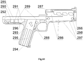
- Figure 61 is an exterior side view of the right half of the trigger housing 260A or 260C and Figure 62 is an interior side view inside of the right half of the trigger housing 260A or 260C.
- the right half of the trigger housing 260A or 260C having threaded hole 266 for the big front nut 32 and handguard 267 in the front part.
- the left half of the trigger housing 261A or 261B having the pistol grip 268 below in the middle.
- the pistol grip 268 having the rectangular hole 269 for safety catch 38 and the complex-shaped hole 299 for the magazine latch 34.
- the hole 301 for the multifunction latch 64 is disposed in the rear part 300 of the right half of the trigger housing 260A or 260C.
- Cross threaded holes 302 for the threaded bushings 264 and threaded bushing with the splineway 265 are disposed on the right half of the trigger housing 260A or 260C.
- the holes 284 for the lower ventilation grooves 262 disposed in the side walls of the handguard 267.
- the channel 285, cavity 286 and slot 287 for installation the receiver with the barrel and mechanisms 62 are disposed within the right half of the trigger housing 260A or 260C.
- the assembly holes 303 for the safety latch 37, safety spring retaining pin 36, magazine latch pusher 35 are disposed upper the pistol grip 268.
- the cavity 288 is configured for the magazine latch 34 as well.
- the cavity 289 is configured for hauling with the hook 39A or 39B and the cavity 290 is configured for the trigger bar spring 41.
- the cavity 291 for the cocking piece 49A or 49B is disposed at the beginning of the cavity 290.
- the rectangular hole 293, inlet conical hole 294, and slots for collecting dirt 295 are configured for the magazine 6.
- the protrusion 304 with the cross hole 305 for the latch of the ramrod 56 and the longitudinal hole 306 for the ramrod 58 are disposed outside on the handguard 267 near the trigger guard 280.
- the through groove 307 is configured for the multifunction latch 43 (only for the right half of the trigger housing 260C).
- the lower rectangular holes 297 and the cylindrical hole 298 are configured for fastening the front handle 4.
- the "T" shaped slot 308 for mounting the gunstock 5 is disposed in the rear part 300 of the right half of the trigger housing 260A or 260C.
- the slot 309 for the spring of the ramrod latch 57 is disposed at the beginning of the cavity 286.
- Figure 61 , Figure 62 showing all elements of the right half of the trigger housing 260A or 260C, their forms and interactions.
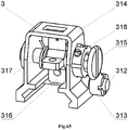
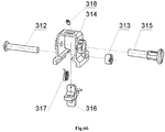
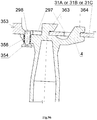
- Figure 64 is a detailing of the adjustable front sight 2 (side view). This configuration comprising: the front sight bracket 310, front sight 311, cap screw 312 and cylindrical nut 313 with the splineway for a screwdriver.
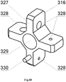
- Figure 68 is side view of the impeller with the diopter holes 316.
- the impeller with the diopter holes 316 having the blades 327 with the diopter holes 328 with the through axial hole 329.
- the retainer pin 330 is disposed on one of the impeller blades 327.
- Figure 68 showing all elements of the impeller with the diopter holes 316, their forms and interactions.
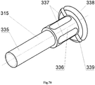
- Figure 69 is a side view of the front sight 311.
- the front sight 311 having the cylindrical section with the thread 331, which passes into a prismatic section 332, which passes into the cylindrical section 333.
- the through slot 334 is disposed in the cylindrical section with the thread 331.
- Figure 69 showing all elements of the front sight 311, their forms and interactions.
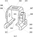
- Threaded hole 347 for the retainer screw 318 is disposed in the cylindrical protrusion 343 on the side surface of the protrusion for the thickness of the wall.
- Cross hole 349 for the adjustment screw 312 disposed in front on the side surface of the plate 340.
- the through longitudinal slot 350 is disposed in front of the wall of the clamp 341 on the entire wall thickness of the plate 340. Because of the through longitudinal slot 350 the front sight bracket 314 works as a spring clip that ensures reliable retention of the front sight bracket 314 to the front sight rail 199.
- Figure 71 showing all elements of the bracket 314, their forms and interactions.
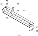
- Figure 72 is a side view of the forward grip 4.
- the forward grip 4 comprising: the body 351 with mounted threaded cover 352 and the retainer spring-loaded by the spring of the locking pin 356 and configured in the form of the locking pin 353, which is mounted in the body 351, the locking pin head 354 is fixed via splint pin of the locking pin 355 is mounted at the end of the locking pin 353 that comes out of the body 351 .
- Figure 73 is a detailing of the forward grip 4 (side view). This configuration comprising: the body 351, threaded cover 352, locking pin 353, locking pin head 354, splint pin of locking pin 355, spring of the locking pin 356.
- Figure 74 is a side view of the body 351.
- the body 351 having the plate 357.
- the holes 358, 359 for locking pin 353 and for spring of the locking pin 356 are disposed in front of the plate 357.
- the rear end of the plate 357 connected to the conical cylindrical part 360, inside of which the cavity 361 with thread 362 at the output for the threaded cover 352 is disposed thereon.
- Two "L" shaped protrusions 363, 364 with the slot 365 disposed on the upper surface in the middle of the plate 357.
- the body used as a wrench for the balancing gear 22 and barrel 24.
- Figure 75 showing all elements of the forward grip body 351 their forms and interactions.
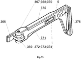
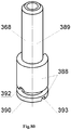
- FIG 75 is a side view of the gunstock 5.
- the gunstock 5 comprising: the bracket of the gunstock 366 having the bushing of the gunstock axis 367, in which the gunstock of the axis 368 spring-loaded with the spring of the gunstock axis 370 and fixed via pin of the gunstock axis 369 in the gunstock base 371 is mounted, the adjustment lever 372 is configured to swing on the axis of the adjustment lever 373 and interact with the gunstock body 375, the smooth recoil pad 376.
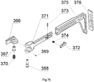
- Figure 76 is a detailing of the gunstock 5 (side view). This configuration comprising: the bracket of the gunstock 366, the bushing of the gunstock axis 367, the gunstock of the axis 368, the pin of the gunstock axis 369, the spring of the gunstock axis 370, the gunstock base 371, the adjustment lever 372, the axis of the adjustment lever 373, the spring of the adjustment lever 374, the gunstock body 375, the smooth recoil pad 376.
- the gunstock body 375 is put on the base of the gunstock 371 and configured to reciprocate along the base of the gunstock 371 and the smooth recoil pad 376 disposed in the gunstock body 375.
- Figure 77 is a front view of the bracket of the gunstock 366 and Figure 78 is a rear view of the bracket of the gunstock 366.
- the gunstock bracket 366 is configured in the form of "T" shaped section 377 with inclined slot 378, blind hole 379 for the multifunction latch 64 and with the locking protrusion 380.
- the complex-shaped protrusion 381 is disposed in the upper part on the other side of the "T" shaped section 377 in the form of the cylinder 382 and in the lower part in the form of the protrusion 383 with inclined sides 384, horizontal platform 385 and radius side 386.
- the through hole 387 for the gunstock of the axis 368 is disposed in the protrusion 381.
- Figure 77 , Figure 78 showing all elements of the bracket of the gunstock 366, their forms and interactions.
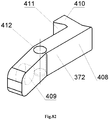
- Figure 82 is a side view of the adjustment lever 372.
- the gunstock adjustment lever 372 is configured in the form of the lever 408 with blind hole 409 on one side for the spring of adjustment lever 374.
- the protrusion 410 with the inclined surface 411 disposed on the other side of the lever 408.
- Through hole 412 for the axis of the adjustment lever 373 is disposed in the middle of the lever 408.
- Figure 82 showing all elements of the adjustment lever 372, their forms and interactions.
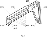
- Figure 83 is a side view of the gunstock body 375.
- the body of the gunstock 375 is configured in the form of the plate 413 with protrusion 414 in the form of a plate, which corresponds with the form of the smooth recoil pad 376.
- the guide "T" shaped blind slot 416 disposed in front of said plate 413 and configured to connect the gunstock body 375 with the gunstock base 371.
- Cross grooves 417 for the adjustment lever 372 are disposed in the guide "T” shaped blind slot 416.
- the first cross groove 417 configured with the chamfer 418 having negative incline 419.
- the rectangular hole 420 disposed in the protrusion 414 for the smooth recoil pad 376.
- Figure 83 showing all elements of the gunstock body 375, their forms and interactions.
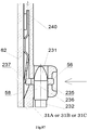
- Figure 86 is a fragment of a cross section of the latch of the ramrod 56 and Figure 87 is a fragment of a longitudinal section of the latch of the ramrod 56. Said figures are showing operation of the latch of the ramrod 56 in the on position. If the ramrod 58 is to be removed, press the latch of the ramrod 56. The front end of the flat spring 237 presses against the receiver with the barrel and mechanisms 62, and the semi-circular slot 236 comes out of the groove 232 of the ramrod 58, while the groove 232 will be located opposite the through semi-circular hole 235, which allows to remove the ramrod 58.
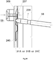
- Figure 88 is disassembly and assembly of the latch of the ramrod 56. If the the latch of the ramrod 56 is to be disassembled, press and hold the latch of the ramrod 56, which will press on the front end of the flat spring 237 and brings it out of the cavity 309 of the trigger housing 31A or 31B or 31C. At the same time, the ramrod 58 is inserted into the through hole 238 of the flat spring 237 and pushes the rear part 240 of the flat spring 237 out of the cavity 309 of the trigger housing 31A or 31B or 31C. At this point, the latch of the ramrod 56 is being disassembled without special tools. If the latch of the ramrod 56 is to be assembled, follow these steps in the reverse order.
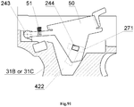
- Figure 89 is showing operation of the slide stop 50 in the off position (side view).
- the slide stop spring 51 pushes against the lever 242 of the slide stop 50.
- the slide stop 50 rotates relative to the hinge 243 and rests against the lower protrusion 246 on section 421, which is located in the cavity 422 of the trigger housing 31B or 31C.
- the plate 241 of the slide stop 50 tightly closes the cavity 422 in the trigger housing 31B or 31C and the cam through hole 271 of the trigger housing 31B or 31C and prevents the water, dirt, dust and sand entering weapons 1A or 1B. All the above mentioned provides reliable operation of the slide stop 50 and weapon 1A or 1B in general.
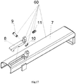
- Figure 92 showing an operation of the receiver cover 7 for the manual rearward movement.
- the bolt carrier 12A or 12B with the bolt 61, the returnable spring 16 and the guide rod of the recoil spring 15 are moved rearward, while the front stop 72 of the receiver cover 7 presses against the support platform 96 of the bolt 12A or 12B.
- enlargement 84 of the bolt carrier 12A or 12B cocks the cocking piece 49C.
- the returnable spring 16 is not involved in the reloading weapons 1B or 1C, thereby reducing the cocking force of weapons and allows to stop the cover of the receiver 7 in any position. This provides convenient access and elimination of light delays when using weapons 1B or 1C in combat conditions.
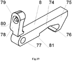
- FIG 93 showing an operation of the cocking lever 8 in the off position.
- the hook 75 of the cocking lever 8 extends beyond the inclined protrusion 213 of the barrel chamber 173 and forms a contact pad in the cylindrical slot 214.
- the inclined protrusion 81 of the cocking lever 8 creates the gap 425 with the bolt carrier of 12A or 12B.
- the cocking lever 8 rotates on the axis of the cocking lever 9 and being pressed by the spring of the cocking lever 11.
- the gap 426 is made between the support platform 96 of the bolt carrier 12A or 12B and the front stop 72 of the receiver cover 7.
- the receiver cover 7 remains stationary and does not have holes.
- Figure 94 showing an operation of the cocking lever 8 in the on position.
- the button 70 of the bracket 68 of the receiver cover 7 and the button 78 of the cocking lever 8 are pressed together.
- the cocking lever 8 rotates on the axis of the cocking lever 9 and the spring of the cocking lever 11 contracts, and the cocking lever 8 is fixed in the on position.
- the hook 75 of the cocking lever 8 extends from the cylindrical slot 214 of the inclined protrusion 213 of the barrel chamber 173.
- the gap 425 between the inclined protrusion 81 of the cocking lever 8 and the bolt carrier 12A or 12B increases.
- the support platform 96 of the slide frame 12A or 12B rests against the front stop 72 of the receiver cover 7.
- Figure 95 showing an operation of the cocking lever 8 for the forward movement.
- the button 70 of the bracket 68 of the receiver cover 7 is pushed forward without using button 78 of the cocking lever 8.
- the inclined protrusion 81 presses against the protrusion 88 of the bolt carrier 12A or 12B, which forces the bolt 61 to forcibly deliver the caseless ammunition 59, including contaminated, from the magazine 6 to the multifunctional cartridge 26.
- This increases the reliability of weapons 1A or 1B or 1C in combat conditions.
- the gap 426 is formed between the front stop 72 of the cover of the receiver 7 and the stop plate 96 of the slide frame 12A or 12B.
- FIG 96 Figure 97 showing assembly and disassembly of the forward grip 4 for the weapon 1A or 1B or 1C.
- the "L" shaped protrusions 363, 364 of the forward grip 4 are set against the lower rectangular holes 297 of the trigger housing 31A or 31B or 31C and press the front handle 4 up to the stop into the trigger housing 31A or 31B or 31C. Then the front handle 4 moves in the direction of the trigger guard 280, while the locking pin 353 of the forward grip 4 engaging with the cylindrical hole 298 of the trigger housing 31A or 31B or 31C.
- forward grip 4 If the forward grip 4 is to be disassemble it is needed to pull on the head of the locking pin 354, wherein said locking pin 353 of the forward grip 4 releases from the engagement with the cylindrical bore 298 of the trigger housing 31A or 31B or 31C, and then to perform the steps reverse to the installation. Easy assembly and disassembly of the forward grip 4 allow to change the configuration of the weapon 1A or 1B or 1C without special tools in any conditions.
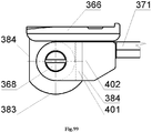
- FIG 98 Figure 99 showing a folding and unfolding of the gunstock 5 for the weapon 1A or 1B or 1C.
- push up the gunstock base 371 and the rectangular slot 402 of the gunstock base 371 coincide with the protrusion 383 of the gunstock bracket 366 and, without releasing it, rotate it at 180 degrees.
- the axis of the gunstock 368 in the gunstock bracket 366 compresses the spring of the gunstock axis 370.
- the gunstock base 371 should be released.
- the inclined platform 401 of the gunstock base 371 engages the gunstock side 384 of the gunstock bracket 366 and fixes the gunstock 5 in this position.
- the inclined platform 401 of the gunstock base 371 and the inclined side 384 of the gunstock bracket 366 are always spring-loaded with the spring of the gunstock axis 370. Due to this, the select of the gap between these sections occurs without assistance and during long-term operation the reliability of the gunstock 5 increases. Fast folding and unfolding of the gunstock 5 allow to change the length of weapons at any time.
- Figure 100 Figure 101 showing an alteration to the length of the gunstock 5 for the weapon 1A or 1B or 1C.
- the spring of the adjustment lever 374 of the gunstock base 371 presses the adjustment lever 372 of the gunstock base 371 and the protrusion 410 with inclined plane 411 of the adjustment lever 372 and said spring 374 enters the transverse grooves 417 of the gunstock body 375.
- the protrusion 410 of the adjustment lever 372 is fixed in the corresponding new transverse groove 417 of the gunstock body 375.
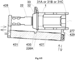
- FIG 106 showing an operation of the weapon 1A in the lock time for the magazine firing.
- the lock time 432 lasts from the beginning of an ignition of the propellant 433 (solid, liquid, gaseous) to the beginning of the piercing of the projectile 434 into the notches of the multifunctional cartridge 26. During this period the following processes occur:
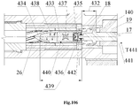
- FIG 107 showing an operation of the weapon 1B and 1C in the lock time for the semi-automatic shot and automatic shot.
- the lock time 432 lasts from the beginning of the ignition of the propellant 433 (solid, liquid, gaseous) to a beginning of the gripping of the projectile 434 into the notches of the multifunctional cartridge 26.
- the following processes occur: after striking the cocking piece 49B on the percussion piston 17, the percussion piston 17 breaks the primer with anvil 435 inside the igniter block 436 and the force flame 437 ignites the propellant 433 (solid, liquid, gaseous). Gases 438 begin to be exhausted with high temperature and pressure. Wherein said igniter block 436 under the action of gases 438 presses on the percussion piston 17.
- the percussion piston 17 moves and selects the gap 443 formed between the cylindrical piston 123 of the percussion piston 17 and the internal surface of the stout wall 116 of the conical bushing of the bolt 18.
- the thickness T443 of the gap 443 depends on many quantities and is set by calculation in each specific case, while the next condition, that the received impulse I should be sufficient for the operation of the weapon's automation is followed.
- the cylindrical piston 123 of the percussion piston 17 under the action of gases 438 will press the conical bushing of the bolt 18 to the glazed area 140 of the shutter housing 19, thereby blocking the leakage of gases 438 into the receiver 30.
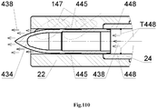
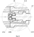
- FIG 111 , Figure 112 , Figure 113 showing an operation of the weapon in the transitional period 450.
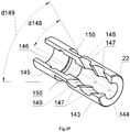
- the transitional period 450 lasts from the moment when the projectile 434 reached the inclined holes 147 of the balancing gear 22 until the gases 438 stop to exert force on the projectile 434. During this period, the following process occurs: The gases 438 passes through the inclined holes 147 of the balancing gear 22 to the outside. The projectile 434 reaches a higher initial velocity Vmax near twenty centimeters from the face of the muzzle of the balancing gear 22.
- the transitional period 450 ends when the gas pressure 438 on the projectile 434 is balanced with atmospheric pressure.
- the claimed new weapon easily adapts to the various types of weapons (pistol, submachine gun, assault rifle, light machine gun, medium machine gun), can be applied for the army, police, hunting, sport and works with maximum efficiency.
Abstract
Description
- Claimed invention relates to firearms, and more particularly to caseless weapons for magazine, semi-automatic, and automatic shot, and can be used to create the designs for shooting with caseless ammunition.
- Some functions of the claimed invention were used in previous firearms designs, more particularly, for example, weapons of Garand and Tokarev with a piston striker and a movable capsule.
- With the advent of modern materials and propellants, it became possible to increase the energy of a shot, while the weight and dimensions of the weapon are reducing. In traditional designs, the weapon is divided into the next types: a pistol, a machine gun, an assault rifle, a light machine gun, an average machine gun, each with its ammunition, and each type of weapon has its optimal principles of automation, design of assemblies and mechanisms. Further reduction of the size and weight, an increase of the weapon power, the acquisition of new properties are possible only with the use of a new designs.
- There are different designs of caseless ammunition, in which a bullet disposed inside the headspace of the propellant charge developed in Austria (1983-1994), France (1980-1986), Germany (1974-1987), the USA (1969-1975). The disadvantage of ammunition when a bullet is inside the headspace is the complicated designs of the weapons.
- In the weapon complex G-11 Germany (watch materials on the website: https://ru.wikipedia.org/wiki/HK G11), or in the LSAT the USA (watch materials on the website: https://ru.wikipedia.org/wiki/LSAT %28%D0%BF%D1%83%D0%BB%D0%B5%D 0%BC%D1%91%D1%82%29), which are known in the prior art, there is also a possibility of self-ignition of ammunition in the weapon chamber and magazines during the long shooting, wherein said weapons have next disadvantages: the insecurity of ammunition during transportation, loss of its features during long storage.
- Designs where the propellant charge disposed in the bullet, were developed in the USA for the weapon Volkanik 1860, Gyroyjet 1965, their disadvantages are the low power of the ammunition, which is no more than 250 J, and the lack of precision of the weapon. In the claimed invention, the propellant disposed within the ammunition. Due to this and to the embodiment features of the weapon and of the ammunition ensured a high power of ammunition up to 3500 J. This allows to develop the necessary energy for specific types of weapons and allows to have different types of weapons on one type of ammunition and one embodiment.
- From the prior art, the automatic caseless weapon system is known (Patent
RU No 2122170 - high friction in the units, which, at shooting can cause incomplete movement of the drum by the front part of the upper chamber to the obturating protrusion of the barrel, and incomplete movement of the obturating protrusion of the bolt to the rear part of the upper chamber;
- the complexity of the embodiment, which consists of a large number of components of complex configuration.
- From the prior art, weapon system with caseless ammunition is known (Patent
RU No 2499214 - at the shot, the weapon system has three joints: The joint between the barrel and the front end of the chamber (for propellants); joint between the rear end of the chamber (for propellants) and the front end of the chamber (for powder charges); joint between the front end of the chamber (for powder charges) and percussion device, in which a breakthrough powder gases can form. This reduces the power of the shot and the reliability of the system. Extremely low survivability of the joints with the obturation of powder gases is known;
- the unhandiness, the complexity of the embodiment with the abundance of rotating and moving parts, which consists of a large number of complex-shaped parts. All this reduces the survivability and reduces the reliability of the weapon. Such weapons can be used in artillery, but in small arms such is unacceptable.
- From the prior art, the automatic firearm is known (Patent
RU No 2478177 - The object of the claimed invention is to improve the design of caseless weapons (variants) that provides next improvement of performance: increase the reliability of the weapon in difficult conditions, reduce the weapons cocking force, provide ease of removing light delays and facilitate loading and unloading, ensure the reliability of weapons in combat conditions with the forced supply of ammunition, including polluted ones, will improve the stability of the projectile trajectory and provide improved accuracy of shots in the arms with a stable position and impromptu shooting.
- The second object of the invention is creating a new embodiment that provides to remove recoil in the magazine weapon and to reduce the effects of vibration during firing in automatic and semi-automatic weapons, increase the effectiveness of the shot, reduce heat loss, reduce the barrel heat and increase the safety of weapons and shooters.
- It is desirable to remove the recoil from the magazine weapon and to reduce the recoil and vibration in small arms when the automatic is working in automatic and semi-automatic weapons. Increase the efficiency of the shot, reduce heat loss and reduce the heating of the barrel, reduce weight and reduce the size of the weapon, improve the safety of the weapon and the shooter, improve the stability of flight projectile on the entire trajectory, to ensure the repair and replacement of parts in field conditions in case of weapon destruction.
- Commonly, it is necessary to cock the weapon, thereby overcoming the force of the mainspring and recoil spring when loading small arms, which can reach five kilograms and more, which is tedious for a fighter. It is advisable to reduce the cocking force.
- During conduct of the battle, it is often necessary to eliminate light delays and facilitate loading and unloading on site. Commonly, this occurs due to juggling of the lock frame, the lock frame is returned by a return spring. Wherein, if there is a delay due to the skew of the cartridge in the chamber and its jamming, then the elimination of the delay by juggling the slide frame will not help. The withdrawal of a fighter under the fire or partial disassembly of weapons under enemy fire is required. The weapon should be configured with the possibility to eliminate these kind of delays without disassembling the weapon.
- In combat conditions, a fighter with a weapon is often being situated in mud, dust, water, sand, which leads to contamination of ammunition, and if there is no forced supply of ammunition, there is a delay in shooting, which threatens the death of a fighter. The weapon should be configured with a forced supply of ammunition.
- It is advisable to have a reliable fixation, convenience, simplicity and speed in installing and removing the slide stop, the magazine latch, the ramrod, the latch on the receiver cover while using all types of small arms.
- The most frequent delays in shooting in difficult conditions arise due to dirt, water, dust and sand getting inside the weapon through all sorts of holes and slots. It is advisable to minimize the places through which dirt, water, dust, and sand can get into the weapon.
- As a result of the long-term operation of a folding adjustable gunstock, play appears in the gunstock fastening unit on the weapon, which reduces the accuracy of shooting. It is advisable to configure the gunstock with the self-removing play. Fighters with different anthropological characteristics use a weapon in a different position: standing, sitting, lying down with a knee. Each position requires its own optimal gunstock length and the ability to quickly mount it. The gunstock should be convenient in operation, folding and adjustable.
- To improve the accuracy of the sniper and hunting weapons shooting from stable positions and impromptu shooting, a gunstock should have a side branch. At the same time, the inconvenience of shooting from the left shoulder appears, which is eliminated by folding the gunstock and using sights with image stabilization.
- It is advisable to have a quick and convenient assembly and disassembly of the forward grip in the weapon, which has a firing forward grip.
- In traditional weapons systems, such as the M-16 system, AK-74, the modular system (Steyr) AUG, the newly developed LSAT system, it is advisable to have specialized weapons workshops in military, police and sportive departments with qualified personnel for complete disassembly and repair of weapons, which increases the cost of the weapon and eliminates disassembly and assembly of the weapon and repair of weapons by the shooter right in the field. Therefore, the weapon system should provide disassembly and assembly of the weapon without the special tools in the field.
- The tasks are solved by the fact that according to the first variant of the invention a caseless magazine weapon (1A), which contains a receiver cover (7), and interacts with a receiver (30), and a bolt carrier (12A) which is configured to reciprocate in a channel guide (178), in which a bolt is mounted (61), which is configured to reciprocate and rotate about an axis, wherein said receiver (30) mounted in a trigger housing (31A) and fixed by multifunction latch (64), a magazine (6) is mounted in the trigger housing (31A) and interacting with the magazine latch (34), and a conical bushing of the receiver (27) is mounted in the receiver (30) and a multifunctional cartridge (26) is mounted on said conical bushing of the receiver (27);
a barrel (24), at the front end of which spring-loaded washer of the balancing gear (23) is put on and the balancing gear (22) is screwed on, and the rear end is screwed in the receiver (30) and fixed with a barrel latch (25);
an extractor (28), fixed in the receiver (30) via lock washer of the extractor (29) and which has the possibility to swing in the receiver (30) about its axis and interacting with the bolt carrier (12A);
fixed forepart in the trigger housing (31A) a big front nut (32), with the front swivel (33) mounted on it,
a ramrod (58), fixed in the trigger housing (31A) and in the receiver (30), and interacting with the latch of the ramrod (56), which is spring-loaded by spring of the latch of the ramrod (57) and mounted in the trigger housing (31A);
a safety catch (38), spring-loaded through safety latch (37) by the safety latch spring (36), which is located in the trigger housing (31A), and configured to reciprocate;
a trigger bar for a semi-automatic weapon (39A), configured together with a sear (40) and affected by the spring of the trigger bar (41) has the possibility to reciprocate in the trigger housing (31A), wherein said spring of the trigger bar (41) is configured to compress and expand in the trigger housing (31A) ;
a percussion mechanism (221) for magazine shot is fixed in the trigger housing (31A), and comprising a bracket of the percussion mechanism (46), a cocking piece (49A) with a cocking indicator mounted on the axis of the cocking piece (47), and a spiral mainspring (48), wherein said cocking piece (49A) is spring-loaded with the spiral mainspring (48), and interacting with enlargement (84) of the bolt carrier (12A) and the sear (40) ;
a removable adjustable front sight (2), a removable adjustable dioptrical sight (3), a forward grip (4), a gunstock (5), wherein,
the receiver cover (7) has a box-section body (65), which contains a rear plate (66), and a bushing (67) is disposed inside of the internal side of said rear plate (66), the bushing configured to interact with a stock (13), and a bracket (68) for the cocking lever (8) is disposed on the external side in the front part of body (65), wherein the bracket (68) has the through hole (69) for the axis of the cocking lever (9), and a button (70) in the form of washer with blind hole (71) for the cocking lever spring (11) is disposed in the rear part of bracket (68), wherein a front stop (72) configured to interact with a support platform (96) of the bolt carrier (12A) and disposed within the top of the body (65), and inside of the body (65) protrusion with an interior chamfer (73) disposed outside and configured to interact with an inclined area (254) of multifunction latch (64), wherein the cocking lever (8), which is configured to interact with the receiver (30) and the bolt carrier (12A), mounted on the axis of the cocking lever (9), whichfixed by lock washer of the axis of the cocking lever (10);
the cocking lever (8) contains the lever (74), which has a hook (75) in the rear part, wherein hook has rounded end (76) and configured to interact with an inclined protrusion (213) and its cylindrical slot (214) of a barrel chamber (173), and a through hole (77) for the axis of the cocking lever (9) disposed in front lower part of said cocking lever (8), the protrusion in form of a button (78) with a blind hole (79) and a cylindrical protrusion (80) for the cocking lever spring (11) disposed in the front part of lever (74), wherein outer coil of the cocking lever spring (11) is pressed on the cylindrical protrusion (80), and between the hook (75) and through hole (77) inclined protrusion (81) with incline to the hook side (75) disposed therein and configured to interact with the protrusion (88) of the bolt carrier (12A);
magazine latch (34) configured to rotate and spring-loaded through magazine latch pusher (35) by safety spring retaining pin (36) ;
the bolt carrier (12A) comprises the bar, the lower part of which has the form of a trapezoidal section (83), and enlargement (84), which configured to interact with the cocking piece (49A) and disposed in the rear part of a trapezoidal section (83);
the guided protrusions (86) disposed on the side surface of a bar (82), wherein said guided protrusions (86) are configured to interact with a channel guide (178) of the receiver (30), wherein front upper part of the bar (82) shaped in the form of console (87), a protrusion (88) disposed at the top in front of said console (87) and configured to interact with an inclined protrusion (81) of the cocking lever (8), and a slot (89) disposed on the edge in front part of said console (87), wherein a blind hole (90) disposed inside of the lower part of the bar (82) and configured to reciprocate the shutter housing (19), a through hole (91) disposed on the bottom of the blind hole (90) and configured to reciprocate a percussion piston (17), wherein through hole (92) and blind hole (93) disposed within upper part of the bar (82), and said blind hole (93) configured to interaction between the operating rod spring (14) and the rod (13) ;
an inlet chamfer (94) disposed in front of the trapezoidal section (83) and configured to interact with caseless ammunition (59), the support platform (95) disposed at the beginning of the console (87) near with through hole (92), wherein a support platform (96) disposed on the front part of console (87) and configured to interact with the front stop (72) of receiver cover (7), wherein gap (426) disposed between the support platform (96) of the bolt carrier (12A) and the front stop (72) of receiver cover (7), and cam slot (97) disposed on the lower surface of console (87) and configured to interact with a leading protrusion (132) of the shutter housing (19), wherein said cam slot configured in form of a screwed groove, which has inlet slot (98), leading edge (99), edge (100) for rotation of the shutter housing (19), free running internal edge (101), the support platform (102), and external leading edge (103), wherein edge (100) and external leading edge (103) form an acute angle (104) to the axis of the bolt (105) and measure of an acute angle (d104) is equal to 30-45 degrees, and leading edge (99) and the axis of bolt (105) form a straight angle (106);
the bolt (61) comprises the percussion piston (17) mounted in a conical bushing (18) and put in the central cylinder channel (141) of the shutter housing (19) configured to reciprocate and spring-loaded by spring of the firing percussion (21) and fixed with the safety catch of the firing percussion (20) ;
the percussion piston (17) configured in stepped shaft form, which has the conical section (118) forepart, which passes into a cylindrical section with smaller diameter (119), wherein an inclined protrusion (120) disposed at the joint of the conical section (118) and the cylindrical section with smaller diameter (119), wherein angle of the protrusion incline (d120) to axis of the firing percussion (121) is equal to 30-45 degrees, and the cylindrical section with smaller diameter (119) passes into the cylindrical section with bigger diameter (122), which passes into the cylindrical piston (123), wherein said piston (123) passes into the rod section with grooves (124);
the conical bushing of the bolt (18) configured to rotate on the percussion piston (17) and pressed by the spring of the firing percussion (21) to a glazed area (140) at the end of a cylindrical head (127) of the shutter housing (19), wherein said conical bushing on the bolt (18) configured as a truncated cone (113) with a blind conical hole (114), which comes into a through hole (115), which forms the stout wall (116) at the outlet of big base of the truncated cone (113), and at inlet in the blind conical hole (114) figured not less than three protrusions (117), which are interacting with the caseless ammunition (59);
the shutter housing (19) has a cylindrical section (125), which passes into a thickened cylindrical section (126), which passes into a cylindrical head (127), and through passage from the cylindrical section (125) to the thickened cylindrical section (126), a chamfer (128) is disposed therein, wherein in junction point between the thickened cylindrical section (126) and the cylindrical head (127) a locking lug (129) is disposed thereon in the form of not less than two protrusions, ends of which configured as the radius surfaces (130), wherein in junction point between the cylindrical section (125) and the thickened cylindrical section (126) the stepped protrusion is disposed therein, which comprising the base (131) and the leading protrusion (132), configured to interact with cam slot (97) of the bolt carrier (12A), and the leading protrusion (132) has a rear leading edge (133), side edge of free running (134) and (135), rear radius chamfers (136), external sideway forepart scarf (137) and external radius section (138), wherein base (131) is at angle to the locking lug (129) and two cylindrical grooves with inclined sides (139) disposed on said base (131), and the glazed area (140) disposed at the end of cylindrical head (127);
a central cylindrical channel (141) disposed within the shutter housing (19) and configured to interact with percussion piston (17), and rear part of the central cylindrical channel (141) has a blind cylindrical hole (142) with bigger diameter, which configured to interact with the firing percussion spring (21) and the safety catch of the firing percussion (20);
a spring washer of the balancing gear (23) configured as a split ring (151) and a three-sided flange (152) on the internal side, and ends of the split ring (151) have bias (153), wherein the measure of bias (T153) is 0.2D23, where D23 - is the outer diameter of the spring washer of the balancing gear (23);
the barrel (24) has a smooth conical section (154), which passes into a threaded section (155), which passes into a slot (156), which passes into a cylindrical section with a splineway (157), which passes into the cylindrical section (158) which passes into a multifaceted area (159), which passes into a smooth cylindrical section with a groove (160), wherein the smooth cylindrical section with the groove (160) passes into a circular groove (161), which passes into a threaded section with a buttress thread (162), which passes into a smooth cylindrical section (163), and the internal channel (164) is smooth without rifling, wherein said barrel sections (24) have different thickness;
the multifunctional cartridge (26) comprising a threaded bushing (165), an internal smooth bushing (166), at least one middle bushing (167) and an external bushing with variable diameter (168), which has bigger diameter (169), wherein the threaded bushing (165) configured with two or more undercut grooves and bushings (165), (166), (167) and (168) are inserted into each other with tension;
the conical bushing of the receiver (27) has a cylindrical section (170) which passes into the smaller cylindrical section (171), and a conical hole (172) disposed inside of said conical bushing of the receiver (27) and configured to interact with the conical bushing of the bolt (18), the small base of which is located at the end of the cylindrical section (170);
wherein the receiver (30) comprising: - the barrel chamber (173) which is screwed in with a locking screw of barrel chamber (174) to the lower part of the receiver (181) ;
- a feed ramp (175) configured in the form of a plate with a threaded hole (176) in the middle, and screwed in with a fastening screw of the guide of the projectile (177) to the lower part of the receiver (181);
- channel guides (178) with threaded holes (179);
- the upper grooves (180), which are disposed on the external surface of the channel guides (178), and configured to interact with the receiver cover (7),
- and in the lower part of the receiver (181) holes disposed on the side walls (182), which configured to be fixed with the screws (184) of the barrel chamber (173) and the channel guides (178) ;
- the lower part of the receiver (181) configured in the form of a box-section figure, wherein cam hole (183) disposed on the bottom of the lower part of the receiver (181);
- a stop (185) with a rear swivel (189) and the cross through hole (186), which configured to interact with the multi-function latch (64) and two vertical threaded holes, wherein said stop is mounted on the rear part of the receiver (181) below via screws (188) ;
- the lower part of the bracket (190) containing threaded holes (191) for fastening the bracket (190) to the lower part of the receiver (181) with the screws (192) and a longitudinal hole (193), which configured to interact with a ramrod (58);
- a threaded hole disposed (194) on top of the bracket (190), for fastening the rear sight rail (196) with the screw (195);
- on a rear sight Picatinny-type rail (196) with a dovetail type slot (197), a hole (198) disposed in the middle of the slot (197) ;
- on a front sight Picatinny-type rail (196) with the dovetail type slot (197), the hole (198) disposed in the middle of the slot (197);
- a plate (200) on which a hole is disposed in the middle (201), which configured to interact with the extractor (28), and two threaded holes (202) disposed thereon at the edges, which configured for fastening the plate (200) to the lower part of the receiver (181) with screws (203);
- the barrel chamber (173) has a cylindrical part (204), and at the end of said cylindrical part (204) within which a multistage cylindrical hole with a threaded section (205) is disposed, which configured to mounting the conical bushing of the receiver (27), the multifunctional cartridge (26) and the barrel (24), wherein at the inlet of said multistage cylindrical hole (205) is a cross threaded hole (206) in the lower part, which is configured to mounting the barrel latch (25), wherein said multistage cylindrical hole (205) passes into the cylindrical groove (207), the lower part of which has a threaded hole (208) for the locking screw of the barrel chamber (174), and the cylindrical groove (207) passes into a complex-shaped section (209), which follows the shape of the front part of shutter housing (19), wherein on the inlet of the complex-shaped section (209) have two leading cylindrical guiding chamfers (210) disposed thereon, and in the middle at the top of the cylindrical section (204) the base with a dovetail-type protrusion (211) disposed therein, in which is disposed the threaded hole (212) for a screw (195) for fastening the front sight rail (199), wherein at the end of the cylindrical part (204) the inclined protrusion (213) disposed thereon, for interaction with the cocking lever (8), and a cylindrical groove (214) disposed on said inclined protrusion (213), wherein the rear end of the cylindrical part (204) has consoles (215) in the form of channel guides, which is configured to interact with the bolt carrier (12A) and the shutter housing (19), and in said consoles (215) in which the cross threaded holes (179) for cap screws (184) to connecting with the barrel chamber (173) with the lower part of the receiver (181), wherein the upper grooves (216) disposed on the external surface of the cylindrical part (204), configured to interact with the receiver cover (7);
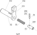
- a multifunction latch (64) contains a multifunction latch lever (52), within which a blind hole (258) is disposed, in which a spring of the lock pin splint (55) and a multifunctional latch stop (53) are mounted in series, wherein the lever of the multifunctional latch (52) within which a through cross hole (249) is disposed and the lock pin (54) is mounted, which has spherical ends (250) and a groove in the middle (251), and said lock pin (54) is disposed within the multifunction latch lever (52) and fixed in the through slot (259), the lock pin spring (55) and the multifunction latch stop (53), wherein the multifunction latch stop (53) and a lock pin (54) are configured to reciprocate in the multifunction latch lever (52), wherein the multifunction latch lever (52) is configured in the form of a rod (252), in front of which a lever (253) disposed therein, and protrusions, rear (256) and front (257) are disposed on the enlargement (255), which disposed at the end of the lever (253), wherein a blind hole (258) disposed in the rod (252) from the side of the lever (253) wherein the through slot (259) disposed in the rod (252);
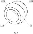
- a big front nut (32) on which the front swivel (33) is mounted thereon, has the possibility of rotation by 360 degrees relative to the axis of the big front nut (32) and is screwed in into the front of the trigger box (31A) to press the front swivel (33) to the trigger box (31A), wherein the big front nut (32) is configured in the form of a truncated cone (223), which passes into a cylindrical section with an external thread (224), and the through hole (225) disposed in said nut;
- a front swivel (33) is configured in the form of a ring (226), on the side of which the protrusion (226A) and a sling swivel (227) are disposed in the form of an oval ring;
- the latch of the ramrod (56) is configured in the form of a plate (233) with rounded protrusions (234) on the lower part, wherein a through semi-circular hole (235) disposed in the center of the plate (233), and a semi-circular slot (236) is disposed in the lower part of the through hole (235);
- the spring of the latch of the ramrod (57) is configured in the form of a flat spring (237), which has through hole (238) at the front end, wherein a bulge (239) is disposed in the middle of the flat spring, and the rear part (240) of the flat spring is rounded;
- the trigger box (31A) comprising the right half of the trigger box (260A) and left half of the trigger box (261A), which are connected to each other by the cap screws (263) with threaded bushings (264) and a threaded bushing with a splineway (265), and lower ventilation bushings (262) disposed on the sides of said trigger box (31A) in the lower part, wherein the right half of the trigger box (260A) and the left half of the trigger box (261A) form the pistol grip (268) of the trigger box (31A), and in the front part they form a threaded hole (266) for interaction with the big front nut (32) and a handguard (267);
- the removable adjustable front sight (2) contains a front sight bracket (310) into which the front sight is screwed in (311), wherein the front sight bracket (310) is mounted on the front sight Picatinny-type rail (199) by cap screw (312) and a cylindrical nut (313);
- the front sight bracket (310) contains a plate (319), which passes into a clamp (320), which is configured in the form of a curved plate of a trapezoidal shape, and a complex-shaped through slot (321) follows the shape of the sight Picatinny-type rail is disposed within the plate (319),
- and a hole (322) disposed on top in the middle of said clamp (320) configured for the thickness of the clamp wall (320), wherein light holes (323) are disposed on the side walls of the clamp (320) at the junction with the plate (319), wherein a threaded hole (324) is disposed on top in the middle of the plate (319), and a cross hole (325) is disposed at the back on the side surface of the plate (319), wherein a through longitudinal slot (326) is disposed behind the threaded hole (324) in front of the wall of the clamp (320) for the entire thickness of the wall plate (319);
- a removable adjustable diopter sight (3) contains a bracket (314) within which the adjustment screw (315) is mounted, on which an impeller with diopter holes (316) is put on, which has the possibility to rotate on the adjustment screw (315), and is constantly compressed by a conical spring (317), wherein the retainer screw (318), which is mounted in the bracket (314), fixes the adjustment screw (315) against rotation, wherein the bracket (314) is mounted on the rear sight Picatinny-type rail (196) via the adjustment screw (312) and the cylindrical nut (313) ;
- the adjustment screw (315) has a cylindrical section with a thread (335), which passes into a cylindrical section (336), along the perimeter of which the slots (337) are disposed, wherein the cylindrical section (336) passes into a washer (338), and through slot (339) is slotted in the washer (338) and in the cylindrical section (336);
- the impeller with diopter holes (316) is configured with the blades (327) with diopter holes (328) with a through axial hole (329), and a retainer pin (330) is disposed on one of the blades of the impeller (327);
- the bracket (314) is configured in the form of a plate (340), which passes into a clamp (341), which is configured in the form of a curved plate of a trapezoidal shape, wherein the complex-shaped through slot (321) is disposed in said plate (340) and follow the form of the sight Picatinny-type rail, wherein a cross hole (349) disposed in front on the side surface of the plate (340), and the hole (342) disposed in the center of the top of the clamp (341) for the thickness of the clamp wall, and on the side walls of the clamp (341) within which a cylindrical protrusion (343), which has a smooth hole (345), and a cylindrical protrusion (344), which has a threaded hole (346) are disposed thereon, and a threaded hole (347) is disposed in the cylindrical protrusion (343) on the side surface of the protrusion for the thickness of the wall, wherein in the side wall of the clamp (341) from the smooth hole side (345) four holes (348) disposed therein, which are at an angle of ninety degrees to each other, and the through longitudinal slot (350) is disposed in front of the wall of the clamp (341) on the entire wall thickness of the plate (340);
- wherein the gunstock (5) comprising:
- a bracket of the gunstock (366), in which a bushing of the gunstock axis (367) is mounted, in which the spring-loaded with spring of the gunstock axis (370) the gunstock of the axis (368) is mounted, which is fixed via pin of the gunstock axis (369) in the gunstock base (371);
- the gunstock axis (368), which combines the gunstock base (371) with the gunstock bracket (366) and allow the gunstock base (371) to fold, wherein the adjustment lever (372) spring-loaded with spring of adjustment lever (374) is mounted in the gunstock base (371) and configured to swing on the axis of the adjustment lever (373) and interacting with the gunstock body (375) ;
- the gunstock bracket (366) is configured in the form of a "T" shaped section (377) with an inclined slot (378), the blind hole (379) and with a locking protrusion (380), and a complex-shaped protrusion (381) is disposed in the upper part on the other side of the "T" shaped section (377) in the form of a cylinder (382) and in the lower part in the form of a protrusion (383), wherein the protrusion (383) configured with inclined sides (384), a horizontal platform (385) and a radius side (386), wherein a through hole (387) is disposed in the protrusion (381);
- the gunstock axis (368) is configured in the form of a rod (388), which passes into a rod with smaller diameter (389), while a circular groove (390) is disposed in the rod (388), and two slots at 180 degrees along the rod (388), the longitudinal slot (391) and the blind slot (392) are disposed after the circular groove (390), wherein a splineway (393) is disposed at the beginning of the rod (388);
- the gunstock base (371) is configured in the form of a complex-shaped bracket (394) with a "T" shaped protrusion (395), wherein said protrusion (395) has slots (396) for collecting dirt, and behind said protrusion (395) a rectangular slot is disposed therein (397) with the through hole (398) and the blind hole (399), wherein a cross through hole (400) is disposed in the middle of a rectangular slot (397), and at the beginning of the bracket (394) within which an inclined platform (401) and a rectangular slot (402) are disposed thereon, and the upper protrusion (403) and the lower protrusion (404) are mounted thereon, in which the through holes (405) and (406) are mounted, and a through hole (407) is disposed on the side of the lower protrusion (404) ;
- the gunstock adjustment lever (372) is configured in the form of a lever (408), which has a blind hole (409) on one side, and a protrusion (410) with an inclined surface (411) on another side of the lever (408), wherein a through hole (412) is disposed in the middle of the lever (408);
- the gunstock body (375) is put on the base of the gunstock (371) and configured to reciprocate along the base of the gunstock (371) and a smooth recoil pad (376) disposed in the gunstock body (375);
- the body of the gunstock (375) is configured in the form of an "L" plate (413) with a protrusion (414), in the rear part of the said plate (413), the complex-shaped hole (415) disposed in front of the protrusion (414), a guide "T" shaped blind slot (416) disposed in front of said plate (413) and has the cross grooves (417), wherein the first cross groove (417) configured with a chamfer (418), which has an negative incline (419), and a rectangular hole (420) disposed in the protrusion (414).
- The tasks are solved by the fact that according to the second variant of the invention a caseless magazine weapon (1B), which contains a receiver cover (7), and interacts with a receiver (30), and a bolt carrier (12A) which is configured to reciprocate in a channel guide (178) of the receiver (30), in which a bolt is mounted (61), which is configured to reciprocate and rotate about an axis, wherein said receiver (30) mounted in a trigger housing (31B) and fixed by multifunction latch (64), a magazine (6) is mounted in the trigger housing (31B) and interacting with the magazine latch (34), and a conical bushing of the receiver (27) is mounted in the receiver (30) and a multifunctional cartridge (26) is mounted on said conical bushing of the receiver (27);
a barrel (24), at the front end of it spring-loaded washer of a balancing gear (23) is put on and the balancing gear (22) is screwed on, and the rear end is screwed in the receiver (30) and fixed with a barrel latch (25);
an extractor (28), fixed in the receiver (30) via lock washer of the extractor (29) and which has the possibility to swing in the receiver (30) about its axis and interacts with the bolt carrier (12A);
fixed forepart in the trigger housing (31A) a big front screw (32), with the front swivel (33) mounted on it,
a ramrod (58), fixed in the trigger housing (31B) and in the receiver (30), and interacting with the latch of the ramrod (56), which is spring-loaded by spring of the latch of the ramrod (57) and mounted in the trigger housing (31B);
a safety catch (38), spring-loaded through safety latch (37) by the safety latch spring (36), which is located in the trigger housing (31B), and configured to reciprocate;
a trigger bar for a semi-automatic weapon (39A), configured together with a sear (40) and affected by the spring of the trigger bar (41) has the possibility to reciprocate in the trigger housing (31B), in which a single-shot sear (42) is disposed within, which is spring-loaded by trigger bar spring (45) ;
wherein said spring of the trigger bar (41) is configured to compress and expand in the trigger housing (31B);
a percussion mechanism (222) for semi-automatic and automatic shot is fixed in the trigger housing (31B), and comprising a bracket of the percussion mechanism (46), a cocking piece (49B) with a cocking indicator mounted on the axis of the cocking piece (47), and a spiral mainspring (48), wherein said cocking piece (49B) is spring-loaded with the spiral mainspring (48), and interacts with enlargement (84) of the bolt carrier (12A) the sear (40) and single-shot sear (42);
spring-loaded with spring of a slide stop (51), a slide stop (50), which is mounted in the trigger housing (31B), and has the possibility of angular bias, and interacting with locking lug (129) and the shutter housing (19);
a removable adjustable front sight (2), a removable adjustable dioptrical sight (3), a forward grip (4), a gunstock (5), wherein,
the receiver cover (7) has a box-section body (65), which contains a rear plate (66), and a bushing (67) is disposed inside of the internal side of said rear plate (66), the bushing configured to interact with the guide rod of a returnable spring (15), and a bracket (68) for the cocking lever (8) is disposed on the external side in the front part of body (65), wherein the bracket (68) has the through hole (69) for the axis of the cocking lever (9), and a button (70) in the form of washer with blind hole (71) for the cocking lever spring (11) is disposed in the rear part of bracket (68), wherein a front stop (72) configured to interact with a support platform (96) of the bolt carrier (12A) and disposed within the top of the body (65), and inside of the body (65) protrusion with an interior chamfer (73) disposed outside and configured to interact with an inclined area (254) of multifunction latch (64), wherein the cocking lever (8), which is configured to interact with the receiver (30) and the bolt carrier (12A), mounted on the axis of the cocking lever (9), which fixed by lock washer of the axis of the cocking lever (10);
the cocking lever (8) contains the lever (74), which has a hook (75) in the rear part, wherein hook has rounded end (76) and configured to interact with an inclined protrusion (213) and its cylindrical slot (214) of a barrel chamber (173), and a through hole (77) for the axis of the cocking lever (9) disposed in front lower part of said cocking lever (8), the protrusion in form of a button (78) with a blind hole (79) and a cylindrical protrusion (80) for the cocking lever spring (11) disposed in the front part of lever (74), wherein outer coil of the cocking lever spring (11) is pressed on the cylindrical protrusion (80), and between the hook (75) and through hole (77) inclined protrusion (81) with incline to the hook side (75) disposed therein and configured to interact with the protrusion (88) of the bolt carrier (12A);
magazine latch (34) configured to rotate and spring-loaded through magazine latch pusher (35) by safety spring retaining pin (36) ;
the bolt carrier (12A) comprises the bar, the lower part of which has the form of a trapezoidal section (83), and enlargement (84), which configured to interact with the cocking piece (49B) and disposed in the rear part of a trapezoidal section (83);
the guided protrusions (86) disposed on the side surface of a bar (82), wherein said guided protrusions (86) are configured to interact with a channel guide (178) of the receiver (30), wherein front upper part of the bar (82) shaped in the form of console (87), a protrusion (88) disposed at the top in front of said console (87) and configured to interact with an inclined protrusion (81) of the cocking lever (8), and a slot (89) disposed on the edge in front part of said console (87), wherein a blind hole (90) disposed inside of the lower part of the bar (82) and configured to reciprocate the shutter housing (19), a through hole (91) disposed on the bottom of the blind hole (90) and configured to reciprocate a percussion piston (17), wherein through hole (92) configured for the guide rod of a returnable spring (15) reciprocation and blind hole (93) disposed within upper part of the bar (82), and said blind hole (93) configured to interaction between the returnable spring (16) and guide rod of a returnable spring (15);
an inlet chamfer (94) disposed in front of the trapezoidal section (83) and configured to interact with caseless ammunition (59), the support platform (95) disposed at the beginning of the console (87) near with through hole (92), wherein a support platform (96) disposed on the front part of console (87) and configured to interact with the front stop (72) of receiver cover (7), wherein gap (426) disposed between the support platform (96) of the bolt carrier (12A) and the front stop (72) of receiver cover (7), and cam slot (97) disposed on the lower surface of console (87) and configured to interact with a leading protrusion (132) of the shutter housing (19), wherein said cam slot configured in form of a screwed groove, which has inlet slot (98), leading edge (99), edge (100) for rotation of the shutter housing (19), free running internal edge (101), the support platform (102) and external leading edge (103), wherein edge (100) and external leading edge (103) form an acute angle (104) to the axis of the bolt (105) and measure of an acute angle (d104) is equal to 30-45 degrees, and leading edge (99) and the axis of bolt (105) form a straight angle (106);
the bolt (61) comprises the percussion piston (17) mounted in a conical bushing (18) and put in the central cylinder channel (141) of the shutter housing (19) configured to reciprocate and spring-loaded by spring of the firing percussion (21) and fixed with the safety catch of the firing percussion (20) ;
the percussion piston (17) configured in stepped shaft form, which has the conical section (118) forepart, which passes into a cylindrical section with smaller diameter (119), wherein an inclined protrusion (120) disposed at the joint of the conical section (118) and the cylindrical section with smaller diameter (119), wherein angle of the protrusion incline (d120) to axis of the firing percussion (121) is equal to 30-45 degrees, and the cylindrical section with smaller diameter (119) passes into the cylindrical section with bigger diameter (122), which passes into the cylindrical piston (123), wherein said piston (123) passes into the rod section with grooves (124);
the percussion piston (17) is configured with a gap (443), which is made between cylindrical piston (123) of the percussion piston (17) and internal surface of stout wall (116) and conical bushing of the bolt (18);
the conical bushing of the bolt (18) configured to rotate on the percussion piston (17) and pressed by the spring of the firing percussion (21) to a glazed area (140) at the end of a cylindrical head (127) of the shutter housing (19), wherein said conical bushing on the bolt (18) configured as a truncated cone (113) with a blind conical hole (114), which comes into a through hole (115), which forms the stout wall (116) at the outlet of big base of the truncated cone (113), and at inlet in the blind conical hole (114) figured not less than three protrusions (117), which are interacting with the caseless ammunition (59);
the shutter housing (19) configured with a cylindrical section (125), which passes into a thickened cylindrical section (126), which passes into a cylindrical head (127), and through passage from the cylindrical section (125) to the thickened cylindrical section (126), a chamfer (128) is disposed therein, wherein in junction point between the thickened cylindrical section (126) and the cylindrical head (127) a locking lug (129) is disposed thereon in the form of not less than two protrusions, ends of which configured as the radius surfaces (130), wherein in the junction point between the cylindrical section (125) and the thickened cylindrical section (126) the stepped protrusion is disposed therein, which comprising the base (131) and the leading protrusion (132), configured to interact with cam slot (97) of the bolt carrier (12A), and the leading protrusion (132) has a rear leading edge (133), side edge of free running (134) and (135), rear radius chamfers (136), external sideway forepart scarf (137) and external radius section (138), wherein base (131) is at angle to the locking lug (129) and two cylindrical grooves with inclined sides (139) disposed on said base (131), and the glazed area (140) disposed at the end of cylindrical head (127);
a central cylindrical channel (141) disposed within the shutter housing (19) and configured to interact with percussion piston (17), and rear part of the central cylindrical channel (141) has a blind cylindrical hole (142) with bigger diameter, which configured to interact with the firing percussion spring (21) and the safety catch of the firing percussion (20);
a spring washer of the balancing gear (23) configured as a split ring (151) and a three-sided flange (152) on the internal side, and ends of the split ring (151) have bias (153), wherein the measure of bias (T153) is 0.2D23, where D23 - is the outer diameter of the spring washer of the balancing gear (23);
the barrel (24) has a smooth conical section (154), which passes into a threaded section (155), which passes into a slot (156), which passes into a cylindrical section with a splineway (157), which passes into the cylindrical section (158) which passes into a multifaceted area (159), which passes into a smooth cylindrical section with a groove (160), wherein the smooth cylindrical section with the groove (160) passes into a circular groove (161), which passes into a threaded section with a buttress thread (162), which passes into a smooth cylindrical section (163), and the internal channel (164) is smooth without rifling, wherein said barrel sections (24) have different thickness;
the multifunctional cartridge (26) comprising a threaded bushing (165), an internal smooth bushing (166), at least one middle bushing (167) and an external bushing with variable diameter (168), which has bigger diameter (169), wherein the threaded bushing (165) configured with two or more undercut grooves and bushings (165), (166), (167) and (168) are inserted into each other with tension;
the conical bushing of the receiver (27) has a cylindrical section (170) which passes into the smaller cylindrical section (171), and a conical hole (172) disposed inside of said conical bushing of the receiver (27) and configured to interact with the conical bushing of the bolt (18), the small base of which is located at the end of the cylindrical section (170);
wherein the receiver (30) comprising: - the barrel chamber (173) which is screwed in with a locking screw of barrel chamber (174) to the lower part of the receiver (181) ;
- a feed ramp (175) configured in the form of a plate with a threaded hole (176) in the middle, and screwed in with a fastening screw of the guide of the projectile (177) to the lower part of the receiver (181);
- channel guides (178) with threaded holes (179);
- the upper grooves (180), which are disposed on the external surface of the channel guides (178), and configured to interact with the receiver cover (7);
- and in the lower part of the receiver (181) holes disposed on the side walls (182), which configured to be fixed with the screws (184) of the barrel chamber (173) and the channel guides (178) ;
- the lower part of the receiver (181) configured in the form of a box-section figure, wherein cam hole (183) disposed on the bottom of lower part of the receiver (181);
- a stop (185) with a rear swivel (189) and the cross through hole (186), which configured to interact with the multi-function latch (64) and with two vertical threaded holes, wherein said stop is mounted on the rear part of the receiver (181) below via screws (188);
- the lower part of the bracket (190) containing threaded holes (191) for fastening the bracket (190) to the lower part of the receiver (181) via the screws (192) and a longitudinal hole (193), which configured to interact with a ramrod (58);
- a threaded hole disposed (194) on top of the bracket (190), for fastening the rear sight rail (196) via the screw (195);
- on a rear sight Picatinny-type rail (196) with a dovetail type slot (197), a hole (198) disposed in the middle of the slot (197) ;
- on a front sight Picatinny-type rail (196) with the dovetail type slot (197), the hole (198) disposed in the middle of the slot (197);
- a plate (200) on which a hole is disposed in the middle (201), which configured to interact with the extractor (28), and two threaded holes (202) disposed thereon at the edges, which configured for fastening the plate (200) to the lower part of the receiver (181) via screws (203);
- the barrel chamber (173) has a cylindrical part (204), and at the end of said cylindrical part (204) within which a multistage cylindrical hole with a threaded section (205) is disposed, which configured to mounting the conical bushing of the receiver (27), the multifunctional cartridge (26) and the barrel (24), wherein at the inlet of said multistage cylindrical hole (205) is a cross threaded hole (206) in the lower part, which is configured to mounting the barrel latch (25), wherein said multistage cylindrical hole (205) passes into the cylindrical groove (207), the lower part of which has a threaded hole (208) for the locking screw of the barrel chamber (174), and the cylindrical groove (207) passes into a complex-shaped section (209), which follows the shape of the front part of shutter housing (19), wherein on the inlet of the complex-shaped section (209) have two leading cylindrical guiding chamfers (210) disposed thereon, and in the middle at the top of the cylindrical section (204) the base with a dovetail-type protrusion (211) disposed therein, in which is disposed the threaded hole (212) for a screw (195) for fastening the front sight rail (199), wherein at the end of the cylindrical part (204) the inclined protrusion (213) disposed thereon, for interaction with the cocking lever (8), and a cylindrical groove (214) disposed on said inclined protrusion (213), wherein the rear end of the cylindrical part (204) has consoles (215) in the form of channel guides, which is configured to interact with the bolt carrier (12A) and the shutter housing (19), and in said consoles (215) in which the cross threaded holes (179) for cap screws (184) to connecting the barrel chamber (173) with the lower part of the receiver (181), wherein the upper grooves (216) disposed on the external surface of the cylindrical part (204), configured to interact with the receiver cover (7);
- the slide stop (50) configured in the form of a plate (241), in front upper part of which protrusion (242) with a hinge (243) in the form of the washer, is disposed therein, a "T" shaped protrusion (244) disposed on the external side of said plate (241), two protrusions upper protrusion (245) and lower protrusion (246) disposed at the end of said plate (241), and protrusion is disposed (247) on the internal side of said plate (241), wherein a hook (248) disposed on the internal side of lever (242);
- a multifunction latch (64) contains a multifunction latch lever (52), within which a blind hole (258) is disposed, in which a spring of the lock pin splint (55) and a multifunctional latch stop (53) are mounted in series, wherein the lever of the multifunctional latch (52) within which a through cross hole (249) is disposed and the lock pin (54) is mounted, which has spherical ends (250) and a groove in the middle (251), and said lock pin (54) is disposed within the multifunction latch lever (52) and fixed in the through slot (259), the lock pin spring (55) and the multifunction latch stop (53), wherein the multifunction latch stop (53) and a lock pin (54) are configured to reciprocate in the multifunction latch lever (52), wherein the multifunction latch lever (52) is configured in the form of a rod (252), in front of which a lever (253) is disposed therein, and protrusions, rear (256) and front (257) are disposed on the enlargement (255), which disposed at the end of the lever (253), wherein a blind hole (258) disposed in the rod (252) from the side of the lever (253) wherein the through slot (259) disposed in the rod (252);
- a big front nut (32) on which the front swivel (33) is mounted thereon, has the possibility of rotation by 360 degrees relative to the axis of the big front nut (32) and is screwed in into the front of the trigger box (31B) to press the front swivel (33) to the trigger box (31B), wherein the big front nut (32) is configured in the form of a truncated cone (223), which passes into a cylindrical section with an external thread (224), and the through hole (225) disposed in said nut;
- a front swivel (33) is configured in the form of a ring (226), on the side of which the protrusion (226A) and a sling swivel (227) are disposed in the form of an oval ring;
- the latch of the ramrod (56) is configured in the form of a plate (233) with rounded protrusions (234) on the lower part, wherein a through semi-circular hole (235) disposed in the center of the plate (233), and a semi-circular slot (236) is disposed in the lower part of the through hole (235);
- the spring of the latch of the ramrod (57) is configured in the form of a flat spring (237), which has through hole (238) at the front end, wherein a bulge (239) is disposed in the middle of the flat spring, and the rear part (240) of the flat spring is rounded;
- the trigger box (31B) comprising the right half of the trigger box (260A) and left half of the trigger box (261B), which are connected to each other by the cap screws (263) with threaded bushings (264) and a threaded bushing with a splineway (265), and lower ventilation bushings (262) disposed on the sides of said trigger box (31B) in the lower part, wherein the right half of the trigger box (260A) and the left half of the trigger box (261B) form the pistol grip (268) of the trigger box (31B), in which a "T" shaped hole is made (271) for interaction with the slide stop (50) and in the front part they form a threaded hole (266) for interaction with the big front nut (32) and a handguard (267);
- the removable adjustable front sight (2) contains a front sight bracket (310) into which the front sight is screwed in (311), wherein the front sight bracket (310) is mounted on the front sight Picatinny-type rail (199) via the cap screw (312) and a cylindrical nut (313);
- the front sight bracket (310) contains a plate (319), which passes into a clamp (320), which is configured in the form of a curved plate of a trapezoidal shape, and a complex-shaped through slot (321) follows the shape of the sight Picatinny-type rail is disposed within the plate (319),
- and a hole (322) disposed on top in the middle of said clamp (320) configured for the thickness of the clamp wall (320), wherein light holes (323) are disposed on the side walls of the clamp (320) at the junction with the plate (319), wherein a threaded hole (324) is disposed on top in the middle of the plate (319), and a cross hole (325) is disposed at the back on the side surface of the plate (319), wherein a through longitudinal slot (326) is disposed behind the threaded hole (324) in front of the wall of the clamp (320) for the entire thickness of the wall plate (319);
- a removable adjustable diopter sight (3) contains a bracket (314) within which the adjustment screw (315) is mounted, on which an impeller with diopter holes (316) is put on, which has the possibility to rotate on the adjustment screw (315), and is constantly compressed by a conical spring (317), wherein the retainer screw (318), which is mounted in the bracket (314), fixes the adjustment screw (315) against rotation, wherein the bracket (314) is mounted on the rear sight Picatinny-type rail (196) via the adjustment screw (312) and the cylindrical nut (313) ;
- the adjustment screw (315) has a cylindrical section with a thread (335), which passes into a cylindrical section (336), along the perimeter of which the slots (337) are disposed, wherein the cylindrical section (336) passes into a washer (338), and through slot (339) is slotted in the washer (338) and in the cylindrical section (336);
- the impeller with diopter holes (316) is configured with the blades (327) with diopter holes (328) with a through axial hole (329), and a retainer pin (330) is disposed on one of the blades of the impeller (327);
- the bracket (314) is configured in the form of a plate (340), which passes into a clamp (341), which is configured in the form of a curved plate of a trapezoidal shape, wherein the complex-shaped through slot (321) is disposed in said plate (340) and follow the form of the sight Picatinny-type rail, wherein a cross hole (349) disposed in front on the side surface of the plate (340), and the hole (342) disposed in the center of the top of the clamp (341) for the thickness of the clamp wall, and on the side walls of the clamp (341) within which a cylindrical protrusion (343), which has a smooth hole (345), and a cylindrical protrusion (344), which has a threaded hole (346) are disposed thereon, and a threaded hole (347) is disposed in the cylindrical protrusion (343) on the side surface of the protrusion for the thickness of the wall, wherein in the side wall of the clamp (341) from the smooth hole side (345) four holes (348) disposed therein, which are at an angle of ninety degrees to each other, and the through longitudinal slot (350) is disposed in front of the wall of the clamp (341) on the entire wall thickness of the plate (340);
- wherein the gunstock (5) comprising:
- a bracket of the gunstock (366), in which a bushing of the gunstock axis (367) is mounted, in which the spring-loaded with spring of the gunstock axis (370) the gunstock of the axis (368) is mounted, which is fixed via pin of the gunstock axis (369) in the gunstock base (371);
- the gunstock axis (368), which combines the gunstock base (371) with the gunstock bracket (366) and allows the gunstock base (371) to fold, wherein the adjustment lever (372) spring-loaded with spring of adjustment lever (374) is mounted in the gunstock base (371) and configured to swing on the axis of the adjustment lever (373) and interacting with the gunstock body (375) ;
- the gunstock bracket (366) is configured in the form of a "T" shaped section (377) with an inclined slot (378), the blind hole (379) and with a locking protrusion (380), and a complex-shaped protrusion (381) is disposed in the upper part on the other side of the "T" shaped section (377) in the form of a cylinder (382) and in the lower part in the form of a protrusion (383), wherein the protrusion (383) configured with inclined sides (384), a horizontal platform (385) and a radius side (386), wherein a through hole (387) is disposed in the protrusion (381);
- the gunstock axis (368) is configured in the form of a rod (388), which passes into a rod with smaller diameter (389), while a circular groove (390) is disposed in the rod (388), and two slots disposed at 180 degrees along the rod (388), the longitudinal slot (391) and the blind slot (392) are disposed after the circular groove (390), wherein a splineway (393) is disposed at the beginning of the rod (388);
- the gunstock base (371) is configured in the form of a complex-shaped bracket (394) with a "T" shaped protrusion (395), wherein said protrusion (395) has slots (396) for collecting dirt, and behind said protrusion (395) a rectangular slot is disposed therein (397) with the through hole (398) and the blind hole (399), wherein a cross through hole (400) is disposed in the middle of a rectangular slot (397), and at the beginning of the bracket (394) within which an inclined platform (401) and a rectangular slot (402) are disposed thereon, and the upper protrusion (403) and the lower protrusion (404) are mounted thereon, in which the through holes (405) and (406) are mounted, and a through hole (407) is disposed on the side of the lower protrusion (404) ;
- the gunstock adjustment lever (372) is configured in the form of a lever (408), which has a blind hole (409) on one side, and a protrusion (410) with an inclined surface (411) on another side of the lever (408), wherein a through hole (412) is disposed in the middle of the lever (408);
- the gunstock body (375) is put on the base of the gunstock (371) and configured to reciprocate along the base of the gunstock (371) and a smooth recoil pad (376) disposed in the gunstock body (375);
- the body of the gunstock (375) is configured in the form of an "L" plate (413) with a protrusion (414), in the rear part of the said plate (413), the complex-shaped hole (415) disposed in front of the protrusion (414), a guide "T" shaped blind slot (416) disposed in front of said plate (413) and has the cross grooves (417), wherein the first cross groove (417) configured with a chamfer (418), which has an negative incline (419), and a rectangular hole (420) disposed in the protrusion (414).
- The tasks are solved by the fact that according to the third variant of the invention a caseless magazine weapon (1C), which contains a receiver cover (7), and interacts with a receiver (30), and a bolt carrier (12B) which is configured to reciprocate in a channel guide (178) of the receiver (30), in which a bolt is mounted (61), which is configured to reciprocate and rotate about an axis, wherein said receiver (30) mounted in a trigger housing (31C) and fixed by multifunction latch (64), a magazine (6) is mounted in the trigger housing (31C) and interacting with the magazine latch (34), and a conical bushing of the receiver (27) is mounted in the receiver (30) and a multifunctional cartridge (26) is mounted on said conical bushing of the receiver (27);
a barrel (24), at the front end of it spring-loaded washer of the balancing gear (23) is put on and the balancing gear (22) is screwed on, and the rear end is screwed in the receiver (30) and fixed with a barrel latch (25);
an extractor (28), fixed in the receiver (30) via lock washer of the extractor (29) and which has the possibility to swing in the receiver (30) about its axis and interacts with the bolt carrier (12B);
fixed forepart in the trigger housing (31C) a big front nut (32), with the front swivel (33) mounted on it,
a ramrod (58), fixed in the trigger housing (31C) and in the receiver (30), and interacting with the latch of the ramrod (56), which is spring-loaded by spring of the latch of the ramrod (57) and mounted in the trigger housing (31C);
a safety catch (38), spring-loaded through safety latch (37) by the safety latch spring (36), which is located in the trigger housing (31C), and configured to reciprocate;
a trigger bar for a semi-automatic weapon (39B), configured together with a sear (40) and affected by the spring of the trigger bar (41) has the possibility to reciprocate in the trigger housing (31C), in which the multifunction switch (43) is disposed within, which is spring-loaded thtough the multifunction switch axis (44) by the trigger spring (45);
wherein said spring of the trigger bar (41) is configured to compress and expand in the trigger housing (31C);
a percussion mechanism (222) for semi-automatic and automatic shot is fixed in the trigger housing (31C), and comprising a bracket of the percussion mechanism (46), a cocking piece (49B) with a cocking indicator mounted on the axis of the cocking piece (47), and a spiral mainspring (48), wherein said cocking piece (49B) is spring-loaded with the spiral mainspring (48), and interacts with enlargement (84) of the bolt carrier (12B), the sear (40) and the multifunction switch (43);
spring-loaded with spring of a slide stop (51), a slide stop (50), which is mounted in the trigger housing (31C), and has the possibility of angular bias and interacting with locking lug (129) and the shutter housing (19);
a removable adjustable front sight (2) a removable adjustable dioptrical sight (3), a forward grip (4), a gunstock (5), wherein,
the receiver cover (7) has a box-section body (65), which contains a rear plate (66), and a bushing (67) is disposed inside of the internal side of said rear plate (66), the bushing configured to interact with the guide rod of a returnable spring (15), and a bracket (68) for the cocking lever (8) is disposed on the external side in the front part of body (65), wherein the bracket (68) has the through hole (69) for the axis of the cocking lever (9), and a button (70) in the form of washer with blind hole (71) for the cocking lever spring (11) is disposed in the rear part of bracket (68), wherein a front stop (72) configured to interact with a support platform (96) of the bolt carrier (12B) and disposed within the top of the body (65), and inside of the body (65) protrusion with an interior chamfer (73) disposed outside and configured to interact with an inclined area (254) of multifunction latch (64), wherein the cocking lever (8), which is configured to interact with the receiver (30) and the bolt carrier (12B), mounted on the axis of the cocking lever (9), which fixed by lock washer of the axis of the cocking lever (10);
the cocking lever (8) contains the lever (74), which has a hook (75) in the rear part, wherein hook has rounded end (76) and configured to interact with an inclined protrusion (213) and its cylindrical slot (214) of a barrel chamber (173), and a through hole (77) for the axis of the cocking lever (9) disposed in front lower part of said cocking lever (8), the protrusion in form of a button (78) with a blind hole (79) and a cylindrical protrusion (80) for the cocking lever spring (11) disposed in the front part of lever (74), wherein outer coil of the cocking lever spring (11) is pressed on the cylindrical protrusion (80), and between the hook (75) and through hole (77) inclined protrusion (81) with incline to the hook side (75) disposed therein and configured to interact with the protrusion (88) of the bolt carrier (12B);
magazine latch (34) configured to rotate and spring-loaded through magazine latch pusher (35) by safety spring retaining pin (36) ;
the bolt carrier (12B) comprises the bar, the lower part of which has the form of a trapezoidal section (83), and in the rear part of a trapezoidal section (83), in which the enlargement (84), which configured to interact with the cocking piece (49B) and a hook-shaped protrusion (85), which interacts with the multifunction switch (43) in the "automatic fire" mode are disposed therein;
the guided protrusions (86) disposed on the side surface of a bar (82), wherein said guided protrusions (86) are configured to interact with a channel guide (178) of the receiver (30), wherein front upper part of the bar (82) shaped in the form of console (87), a protrusion (88) disposed at the top in front of said console (87) and configured to interact with an inclined protrusion (81) of the cocking lever (8), and a slot (89) disposed on the edge in front part of said console (87), wherein a blind hole (90) disposed inside of the lower part of the bar (82) and configured to reciprocate the shutter housing (19), a through hole (91) disposed on the bottom of the blind hole (90) and configured to reciprocate a percussion piston (17), wherein through hole (92) configured for the guide rod of a returnable spring (15) reciprocation and blind hole (93) disposed within upper part of the bar (82), and said blind hole (93) configured to interaction between the returnable spring (16) and guide rod of a returnable spring (15);
an inlet chamfer (94) disposed in front of the trapezoidal section (83) and configured to interact with caseless ammunition (59), the support platform (95) disposed at the beginning of the console (87) near with through hole (92), wherein a support platform (96) disposed on the front part of console (87) and configured to interact with the front stop (72) of receiver cover (7), wherein gap (426) disposed between the support platform (96) of the bolt carrier (12B) and the front stop (72) of receiver cover (7), and cam slot (97) disposed on the lower surface of console (87) and configured to interact with a leading protrusion (132) of the shutter housing (19), wherein said cam slot configured in form of a screwed groove, which has inlet slot (98), leading edge (99), edge (100) for rotation of the shutter housing (19), free running internal edge (101), the support platform (102) and external leading edge (103), wherein edge (100) and external leading edge (103) form an acute angle (104) to the axis of the bolt (105) and measure of an acute angle (d104) is equal to 30-45 degrees, and leading edge (99) and the axis of bolt (105) form a straight angle (106);
the bolt (61) comprises the percussion piston (17) mounted in a conical bushing (18) and put in the central cylinder channel (141) of the shutter housing (19) configured to reciprocate and spring-loaded by spring of the firing percussion (21) and fixed with the safety catch of the firing percussion (20) ;
the percussion piston (17) configured in stepped shaft form, which has the conical section (118) forepart, which passes into a cylindrical section with smaller diameter (119), wherein an inclined protrusion (120) disposed at the joint of the conical section (118) and the cylindrical section with smaller diameter (119), wherein angle of the protrusion incline (d120) to axis of the firing percussion (121) is equal to 30-45 degrees, and the cylindrical section with smaller diameter (119) passes into the cylindrical section with bigger diameter (122), which passes into the cylindrical piston (123), wherein said piston (123) passes into the rod section with grooves (124);
the percussion piston (17) is configured with a gap (443), which is made between cylindrical piston (123) of the percussion piston (17) and internal surface of stout wall (116) and conical bushing of the bolt (18);
the conical bushing of the bolt (18) configured to rotate on the percussion piston (17) and pressed by the spring of the firing percussion (21) to a glazed area (140) at the end of a cylindrical head (127) of the shutter housing (19), wherein said conical bushing on the bolt (18) configured as a truncated cone (113) with a blind conical hole (114), which comes into a through hole (115), which forms the stout wall (116) at the outlet of big base of the truncated cone (113), and at inlet in the blind conical hole (114) figured not less than three protrusions (117), which are interacting with the caseless ammunition (59);
the shutter housing (19) has a cylindrical section (125), which passes into a thickened cylindrical section (126), which passes into a cylindrical head (127), and through passage from the cylindrical section (125) to the thickened cylindrical section (126), a chamfer (128) is disposed therein, wherein in junction point between the thickened cylindrical section (126) and the cylindrical head (127) a locking lug (129) is disposed thereon in the form of not less than two protrusions, ends of which configured as the radius surfaces (130), wherein in the junction point between the cylindrical section (125) and the thickened cylindrical section (126) the stepped protrusion is disposed therein, which comprising the base (131) and the leading protrusion (132), configured to interact with cam slot (97) of the bolt carrier (12B), and the leading protrusion (132) has a rear leading edge (133), side edge of free running (134) and (135), rear radius chamfers (136), external sideway forepart scarf (137) and external radius section (138), wherein base (131) is at angle to the locking lug (129) and two cylindrical grooves with inclined sides (139) disposed on said base (131), and the glazed area (140) disposed at the end of cylindrical head (127);
a central cylindrical channel (141) disposed within the shutter housing (19) and configured to interact with percussion piston (17), and rear part of the central cylindrical channel (141) has a blind cylindrical hole (142) with bigger diameter, which configured to interact with the firing percussion spring (21) and the safety catch of the firing percussion (20);
a spring washer of the balancing gear (23) configured as a split ring (151) and a three-sided flange (152) on the internal side, and ends of the split ring (151) have bias (153), wherein the measure of bias (T153) is 0.2D23, where D23 - is the outer diameter of the spring washer of the balancing gear (23);
the barrel (24) has a smooth conical section (154), which passes into a threaded section (155), which passes into a slot (156), which passes into a cylindrical section with a splineway (157), which passes into the cylindrical section (158) which passes into a multifaceted area (159), which passes into a smooth cylindrical section with a groove (160), wherein the smooth cylindrical section with the groove (160) passes into a circular groove (161), which passes into a threaded section with a buttress thread (162), which passes into a smooth cylindrical section (163), and the internal channel (164) is smooth without rifling, wherein said barrel sections (24) have different thickness;
the multifunctional cartridge (26) comprising a threaded bushing (165), an internal smooth bushing (166), at least one middle bushing (167) and an external bushing with variable diameter (168), which has bigger diameter (169), wherein the threaded bushing (165) configured with two or more undercut grooves and bushings (165), (166), (167) and (168) are inserted into each other with tension;
the conical bushing of the receiver (27) has a cylindrical section (170) which passes into the smaller cylindrical section (171), and a conical hole (172) disposed inside of said conical bushing of the receiver (27) and configured to interact with the conical bushing of the bolt (18), the small base of which is located at the end of the cylindrical section (170);
wherein the receiver (30) comprising: - the barrel chamber (173) which is screwed in with a locking screw of barrel chamber (174) to the lower part of the receiver (181) ;
- a feed ramp (175) configured in the form of a plate with a threaded hole (176) in the middle, and screwed in with a fastening screw of the guide of the projectile (177) to the lower part of the receiver (181);
- channel guides (178) with threaded holes (179);
- the upper grooves (180), which are disposed on the external surface of the channel guides (178), and configured to interact with the receiver cover (7);
- and in the lower part of the receiver (181) holes disposed on the side walls (182), which configured to be fixed with the screws (184) of the barrel chamber (173) and the channel guides (178) ;
- the lower part of the receiver (181) configured in the form of a box-section figure, wherein cam hole (183) disposed on the bottom of lower part of the receiver (181);
- a stop (185) with a rear swivel (189) and the cross through hole (186), which configured to interact with the multi-function latch (64) and with two vertical threaded holes, wherein said stop is mounted on the rear part of the receiver (181) below via screws (188);
- the lower part of the bracket (190) containing threaded holes (191) for fastening the bracket (190) to the lower part of the receiver (181) via the screws (192) and a longitudinal hole (193), which configured to interact with a ramrod (58);
- a threaded hole disposed (194) on top of the bracket (190), for fastening the rear sight rail (196) via the screw (195);
- on a rear sight Picatinny-type rail (196) with a dovetail type slot (197), a hole (198) disposed in the middle of the slot (197) ;
- on a front sight Picatinny-type rail (196) with the dovetail type slot (197), the hole (198) disposed in the middle of the slot (197);
- a plate (200) on which a hole is disposed in the middle (201), which configured to interact with the extractor (28), and two threaded holes (202) disposed thereon at the edges, which configured for fastening the plate (200) to the lower part of the receiver (181) via screws (203);
- the barrel chamber (173) has a cylindrical part (204), and at the end of said cylindrical part (204) within which a multistage cylindrical hole with a threaded section (205) is disposed, which configured to mounting the conical bushing of the receiver (27), the multifunctional cartridge (26) and the barrel (24), wherein at the inlet of said multistage cylindrical hole (205) is a cross threaded hole (206) in the lower part, which is configured to mounting the barrel latch (25), wherein said multistage cylindrical hole (205) passes into the cylindrical groove (207), the lower part of which has a threaded hole (208) for the locking screw of the barrel chamber (174), and the cylindrical groove (207) passes into a complex-shaped section (209), which follows the shape of the front part of shutter housing (19), wherein on the inlet of the complex-shaped section (209) have two leading cylindrical guiding chamfers (210) disposed thereon, and in the middle at the top of the cylindrical section (204) the base with a dovetail-type protrusion (211) disposed therein, in which is disposed the threaded hole (212) for a screw (195) for fastening the front sight rail (199), wherein at the end of the cylindrical part (204) the inclined protrusion (213) disposed thereon, for interaction with the cocking lever (8), and a cylindrical groove (214) disposed on said inclined protrusion (213), wherein the rear end of the cylindrical part (204) has consoles (215) in the form of channel guides, which is configured to interact with the bolt carrier (12B) and the shutter housing (19), and in said consoles (215) in which the cross threaded holes (179) for cap screws (184) to connecting the barrel chamber (173) with the lower part of the receiver (181), wherein the upper grooves (216) disposed on the external surface of the cylindrical part (204), configured to interact with the receiver cover (7);
- the slide stop (50) configured in the form of a plate (241), in front upper part of which protrusion (242) with a hinge (243) in the form of the washer, is disposed therein, a "T" shaped protrusion (244) disposed on the external side of said plate (241), two protrusions upper protrusion (245) and lower protrusion (246) disposed at the end of said plate (241), and protrusion is disposed (247) on the internal side of said plate (241), wherein a hook (248) disposed on the internal side of lever (242);
- a multifunction latch (64) contains a multifunction latch lever (52), within which a blind hole (258) is disposed, in which a spring of the lock pin splint (55) and a multifunctional latch stop (53) are mounted in series, wherein the lever of the multifunctional latch (52) within which a through cross hole (249) is disposed and the lock pin (54) is mounted, which has spherical ends (250) and a groove in the middle (251), and said lock pin (54) is disposed within the multifunction latch lever (52) and fixed in the through slot (259), the lock pin spring (55) and the multifunction latch stop (53), wherein the multifunction latch stop (53) and a lock pin (54) are configured to reciprocate in the multifunction latch lever (52), wherein the multifunction latch lever (52) is configured in the form of a rod (252), in front of which a lever (253) is disposed therein, and protrusions, rear (256) and front (257) are disposed on the enlargement (255), which disposed at the end of the lever (253), wherein a blind hole (258) disposed in the rod (252) from the side of the lever (253) wherein the through slot (259) disposed in the rod (252);
- a big front nut (32) on which the front swivel (33) is mounted thereon, has the possibility of rotation by 360 degrees relative to the axis of the big front nut (32) and is screwed in into the front of the trigger box (31C) to press the front swivel (33) to the trigger box (31C), wherein the big front nut (32) is configured in the form of a truncated cone (223), which passes into a cylindrical section with an external thread (224), and the through hole (225) disposed in said nut;
- a front swivel (33) is configured in the form of a ring (226), on the side of which the protrusion (226A) and a sling swivel (227) are disposed in the form of an oval ring;
- the latch of the ramrod (56) is configured in the form of a plate (233) with rounded protrusions (234) on the lower part, wherein a through semi-circular hole (235) disposed in the center of the plate (233), and a semi-circular slot (236) is disposed in the lower part of the through hole (235);
- the spring of the latch of the ramrod (57) is configured in the form of a flat spring (237), which has through hole (238) at the front end, wherein a bulge (239) is disposed in the middle of the flat spring, and the rear part (240) of the flat spring is rounded;
- the trigger box (31C) comprising the right half of the trigger box (260C) and left half of the trigger box (261B), which are connected to each other via the cap screws (263) with threaded bushings (264) and a threaded bushing with a splineway (265), and lower ventilation bushings (262) disposed on the sides of said trigger box (31C) in the lower part, wherein the right half of the trigger box (260B) and the left half of the trigger box (261C) form the pistol grip (268) of the trigger box (31C), in which a "T" shaped hole is made (271) for interaction with the slide stop (50) and a through slot (307), which is made for interaction with the multifunction switch (43), and in the front part they form a threaded hole (266) for interaction with the big front nut (32) and a handguard (267);
- the removable adjustable front sight (2) contains a front sight bracket (310) into which the front sight is screwed in (311), wherein the front sight bracket (310) is mounted on the front sight Picatinny-type rail (199) via the cap screw (312) and a cylindrical nut (313);
- the front sight bracket (310) contains a plate (319), which passes into a clamp (320), which is configured in the form of a curved plate of a trapezoidal shape, and a complex-shaped through slot (321) follows the shape of the sight Picatinny-type rail is disposed within the plate (319),
- and a hole (322) disposed on top in the middle of said clamp (320) configured for the thickness of the clamp wall (320), wherein light holes (323) are disposed on the side walls of the clamp (320) at the junction with the plate (319), wherein a threaded hole (324) is disposed on top in the middle of the plate (319), and a cross hole (325) is disposed at the back on the side surface of the plate (319), wherein a through longitudinal slot (326) is disposed behind the threaded hole (324) in front of the wall of the clamp (320) for the entire thickness of the wall plate (319);
- a removable adjustable diopter sight (3) contains a bracket (314) within which the adjustment screw (315) is mounted, on which an impeller with diopter holes (316) is put on, which has the possibility to rotate on the adjustment screw (315), and is constantly compressed by a conical spring (317), wherein the retainer screw (318), which is mounted in the bracket (314), fixes the adjustment screw (315) against rotation, wherein the bracket (314) is mounted on the rear sight Picatinny-type rail (196) via the adjustment screw (312) and the cylindrical nut (313) ;
- the adjustment screw (315) has a cylindrical section with a thread (335), which passes into a cylindrical section (336), along the perimeter of which the slots (337) are disposed, wherein the cylindrical section (336) passes into a washer (338), and through slot (339) is slotted in the washer (338) and in the cylindrical section (336) ;
- the impeller with diopter holes (316) is configured with the blades (327) with diopter holes (328) with a through axial hole (329), and a retainer pin (330) is disposed on one of the blades of the impeller (327);
- the bracket (314) is configured in the form of a plate (340), which passes into a clamp (341), which is configured in the form of a curved plate of a trapezoidal shape, wherein the complex-shaped through slot (321) is disposed in said plate (340) and follow the form of the sight Picatinny-type rail, wherein a cross hole (349) disposed in front on the side surface of the plate (340), and the hole (342) disposed in the center of the top of the clamp (341) for the thickness of the clamp wall, and on the side walls of the clamp (341) within which a cylindrical protrusion (343), which has a smooth hole (345), and a cylindrical protrusion (344), which has a threaded hole (346) are disposed thereon, and a threaded hole (347) is disposed in the cylindrical protrusion (343) on the side surface of the protrusion for the thickness of the wall, wherein in the side wall of the clamp (341) from the smooth hole side (345) four holes (348) disposed therein, which are at an angle of ninety degrees to each other, and the through longitudinal slot (350) is disposed in front of the wall of the clamp (341) on the entire wall thickness of the plate (340);
- wherein the gunstock (5) comprising:
- a bracket of the gunstock (366), in which a bushing of the gunstock axis (367) is mounted, in which the spring-loaded with spring of the gunstock axis (370) the gunstock of the axis (368) is mounted, which is fixed via pin of the gunstock axis (369) in the gunstock base (371);
- the gunstock axis (368), which combines the gunstock base (371) with the gunstock bracket (366) and allows the gunstock base (371) to fold, wherein the adjustment lever (372) spring-loaded with spring of adjustment lever (374) is mounted in the gunstock base (371) and configured to swing on the axis of the adjustment lever (373) and interacting with the gunstock body (375) ;
- the gunstock bracket (366) is configured in the form of a "T" shaped section (377) with an inclined slot (378), the blind hole (379) and with a locking protrusion (380), and a complex-shaped protrusion (381) is disposed in the upper part on the other side of the "T" shaped section (377) in the form of a cylinder (382) and in the lower part in the form of a protrusion (383), wherein the protrusion (383) configured with inclined sides (384), a horizontal platform (385) and a radius side (386), wherein a through hole (387) is disposed in the protrusion (381);
- the gunstock axis (368) is configured in the form of a rod (388), which passes into a rod with smaller diameter (389), while a circular groove (390) is disposed in the rod (388), and two slots disposed at 180 degrees along the rod (388), the longitudinal slot (391) and the blind slot (392) are disposed after the circular groove (390), wherein a splineway (393) is disposed at the beginning of the rod (388);
- the gunstock base (371) is configured in the form of a complex-shaped bracket (394) with a "T" shaped protrusion (395), wherein said protrusion (395) has slots (396) for collecting dirt, and behind said protrusion (395) a rectangular slot is disposed therein (397) with the through hole (398) and the blind hole (399), wherein a cross through hole (400) is disposed in the middle of a rectangular slot (397), and at the beginning of the bracket (394) within which an inclined platform (401) and a rectangular slot (402) are disposed thereon, and the upper protrusion (403) and the lower protrusion (404) are mounted thereon, in which the through holes (405) and (406) are mounted, and a through hole (407) is disposed on the side of the lower protrusion (404) ;
- the gunstock adjustment lever (372) is configured in the form of a lever (408), which has a blind hole (409) on one side, and a protrusion (410) with an inclined surface (411) on the other side of the lever (408), wherein a through hole (412) is disposed in the middle of the lever (408);
- the gunstock body (375) is put on the base of the gunstock (371) and configured to reciprocate along the base of the gunstock (371) and a smooth recoil pad (376) disposed in the gunstock body (375);
- the body of the gunstock (375) is configured in the form of an "L" plate (413) with a protrusion (414), in the rear part of the said plate (413), the complex-shaped hole (415) disposed in front of the protrusion (414), a guide "T" shaped blind slot (416) disposed in front of said plate (413) and has the cross grooves (417), wherein the first cross groove (417) configured with a chamfer (418), which has an negative incline (419), and a rectangular hole (420) disposed in the protrusion (414).
- Besides, the rod (13) is configured with the washer with the radial chamfer (107), which passes into cylindrical part (108), which passes into the washer with the radial chamfer (107).
- Besides, the guide rod (15) is configured with the spherical head (109), which passes into cylindrical part (110), which via a conical transition (111) passes into cylindrical part (112) with bigger diameter, which passes into the washer with radial chamfer (107).
- Besides, the balancing gear (22) is configured in the form of a cylinder (143), inside of which a smooth cylindrical section (144) is disposed, which passes into a conical section (145), which passes into a cylindrical groove with threaded section (146), and in the front of the cylinder (143) there inclined holes (147) are disposed with an acute angle (148) to the longitudinal axis, and slots (150) are disposed behind the inclined holes (147) on the outer part of the cylinder (143), wherein said inclined holes (147) in the cross-section between them formed an angle (149).
- Besides, the ramrod (58) is configured in the form of a rod (228), at the front end of which a slotted groove (229) is disposed, which passes into the flat end (230), a groove (232) is disposed in front of the rear end of the rod (228) which is configured in the form of a conical head (231).
- Besides, the front sight (311) has a cylindrical section with a thread (331), which passes into a prismatic section (332), which passes into a cylindrical section (333), and a through slot (334) is disposed in the cylindrical section with thread (331).
- Besides, the forward grip (4) comprising a body (351) in which a threaded cover (352) and a retainer spring-loaded with a spring of a locking pin (356) are mounted, and configured in the form of a locking pin (353), which is mounted in the body (351), and at the end of the locking pin (353) coming out of the body (351), a locking pin head (354) is mounted, which is fixed with a splint pin of the locking pin (355).
- Besides, the body (351) is configured with a plate (357), in front of which there are holes (358), (359), wherein the rear end of the plate (357) connected to the conical cylindrical part (360), in which a cavity (361) is formed with a thread (362) at the exit, and on the upper surface in the middle of the plate (357) there are two "L" protrusions (363) and (364) with a slot (365) .
- Preferably, the threaded bushing (165) and the inner smooth bushing (166) are made of carbide and refractory material.
- Besides, the caseless magazine weapon (1A) is additionally equipped with a knife-bayonet (427), which contains a front stop with a ring (428), a handle (431) with a slot (430) and a back stop with a hook-shaped protrusion (429).
- Besides, the caseless semi-automatic weapon (1B) is additionally equipped with a bayonet-knife (427), which contains a front stop with a ring (428), a handle (431) with a slot (430) and a back stop with hook-shaped protrusion (429).
- Besides, the caseless automatic weapon (1C) is additionally equipped with a bayonet-knife (427), which contains a front stop with a ring (428), a handle (431) with a slot (430) and a back stop with hook-shaped protrusion (429).
- Improving the reliability of the weapon's operation in difficult conditions (dirt, water, dust, sand) is achieved by the fact that: when the automatic equipment of the proposed weapon is working, the receiver cover is fixed in the closed state, has no open windows. The only open window for the cocking lever of the receiver cover is securely closed by the cocking lever itself.
- A reduction in the cocking force of the weapons, the convenience of eliminating light delays and facilitating loading and unloading in the claimed weapon is achieved by the fact that: when you manually rollback, the ledge of the receiver stays in place, wherein the cover of the receiver, the slide frame with the bolt and return mechanism are rolling back. At the same time, the recoil spring having a static position and does not participate in the rollback, which allows stopping the receiver cover over the entire length of the rollback. This provides convenient access to eliminate light delays in combat conditions. The recoil spring is not involved in reloading the weapon, thus reducing the cocking effort, and facilitates the loading and the unloading of the weapon.
- Ensuring the reliability of weapons with the forced supply of ammunition, including contaminated in combat conditions is achieved by the fact that: when manually feeding in front of the receiver cover, the cocking lever should be in the closed position. Wherein the cocking lever with its inclined ledge under the action of a spring descends and rests against the shoulder of the lock frame. The inclined ledge resting on the ledge of the lock frame leads forcibly to the lock frame, which ensures the forced supply of ammunition, including contaminated, from the magazine to the multifunctional cartridge. This increases the reliability of weapons in combat conditions.
- Ensuring ease of operation and firing accuracy when using the multifunction switch is achieved by the fact that: at the time of switching fire modes, the shooter does not lead the away from the aiming line, does not take his eyes off the aiming devices, and the switch is made with the thumb of any hand thus, the multifunction switch increases the efficiency and accuracy of shooting.
- In the claimed weapon the slide stop plate tightly closes the cavity with a hole and prevents getting dirt, sand and water inside of the weapon, which ensures reliable operation of the slide stop in difficult conditions.
- A distinctive feature of the proposed invention is the ammunition, which has surrounded by a large mass of metal (multilayer and multifunction cartridge, receiver, and bolt) when fired. The projectile has a wall thickness of 1.5-2 times more than the case wall in traditional weapons, which gives greater thermal inertia, and the free gap between the walls of the multifunctional cartridge and the walls of the projectile reduces the contact zone of heat transfer from the heated multifunctional cartridge to the projectile. Thus, the moment of spontaneous self-ignition of the projectile inside of the heated weapon is significantly distancing.
- Also in the claimed weapon, the ramrod is removed when pressing inside the ramrod latch. One end of the spring of the ramrod latch will press down on the receiver. The semi-circular slot of the ramrod latch will come out of the ramrod's circular groove, which with the conical head will slide into the ramrod latch through the semi-circular hole and can be completely removed from the weapon. It is necessary to press the ramrod latch by the conical head of the ramrod and fixed it in site when putting the ramrod back on the weapon. This simplifies and speeds up the attachment of the ramrod to the weapon in field conditions and provides a reliable fixation of the ramrod and ease of installation and removal of the ramrod.
- Another feature of the present invention is ensuring the reliability and ease of use of multifunctional latches. This is achieved by the fact that when the multifunction latch rotates counterclockwise approximately at 45 degrees and moves along the inclined surface of the trigger box, the ledge of the multifunction latch lever is removed from the blind hole of the bracket of the folding adjustable gunstock. At this point, the receiver cover and folding adjustable gunstock removed from the weapon. Attaching the folding adjustable gunstock back to the arms can be done by pressing on the ledge of the multifunctional latch with an inclined slot on the gunstock bracket.
- The use of the present invention provides adjustment and elimination of play, as well as easy operation of the folding adjustable gunstock. This is achieved by the fact that: due to the presence of the inclined area of the gunstock base and the inclined side edge of the gunstock bracket in combination with the constant spring pressure of the gunstock axis on the bracket of the gunstock and the gunstock base, there is an automatic selection of the gap between these areas, which appears as a result of long-term operation, which eliminates play unit and improves shooting accuracy. Rapid folding and unfolding of the adjustable gunstock allow resizing weapons following the need to solve various problems. You need to press down on the bottom rounded ledge of the gunstock base to fold or to unfold the adjustable gunstock. Then, without slackening the pressure on the gunstock base, turn the gunstock body through 180° and release the base. The ability to lengthen and shorten the length of the adjustable gunstock gives ease of use of the weapon when shooting while standing, sitting and lying, as well as using weapons by a shooter with different anthropological characteristics. It is necessary to press the gunstock adjustment lever and push the gunstock body to the desired length and to release the lever when adjustment of the gunstock base is completed. The gunstock with a side branch provided improving the accuracy of weapons shooting from stable positions and from impromptu shooting.
- Another feature of the present invention is to provide quick and easy assembly and disassembly of the front handle. This is achieved through the following actions: for installation, it is necessary to combine the front ledge and the rear ledge of the body with the lower ventilation holes on the trigger box with the handle and handguard. Next, push on the case to the full, and move the case in the direction of the trigger guard to the full. To disassembly, pull the head of the locking pin with the transverse hole on the handle, and move the handle forward to remove it.
- In claimed weapon, a container is arranged in the front handle, and the front handle body having two L-shaped ledges with a triangular groove for the wrench for removing or installing the flame arrester compensator and the barrel in field conditions, which has bigger functionality by having the front handle. Another claimed feature of the proposed weapon is the possibility to disassemble the magazine, semiautomatic and automatic caseless weapons to pieces to the factory level and then assemble it without any special tools in any conditions.
- The brief description of the drawings:
-
Figure 1A is a schematic side view of theweapon 1A. -
Figure 1B is a schematic side view of theweapon 1B. -
Figure 1C is a schematic side view of theweapon 1C. -
Figure 2A is a schematic side view of theweapon 1A. -
Figure 2B is a schematic side view of theweapon 1B. -
Figure 2C is a schematic side view of theweapon 1C. -
Figure 3A is a schematic side view of theweapon 1A with folded gunstock. -
Figure 3B is a schematic side view of the weapon 3B with folded gunstock. -
Figure 3C is a schematic side view of the weapon 3C with folded gunstock. -
Figure 4 is a side view of theweapon -
Figure 5 is a side view of the 1A or 1B or 1C. -
Figure 6A is a longitudinal section of theweapon 1A in magazine embodiment. -
Figure 6B is a longitudinal section of theweapon 1B in semi-automatic embodiment. -
Figure 6C is a longitudinal section of theweapon 1C in automatic embodiment. -
Figure 7 is a fragment of a longitudinal section of theweapon pusher 6 of themagazine latch 35. -
Figure 8 is a cross-section 1-1 onFigure 4 . -
Figure 9 is a cross-section 2-2 onFigure 5 . -
Figure 10 is a fragment of a longitudinal section of theweapon 1B on the single-shot sear 42. -
Figure 11 is a fragment of a longitudinal section of theweapon 1C on the themultifunction switch 43. -
Figure 12 is a fragment of a longitudinal section of theweapon slide stop 50. -
Figure 13 is a cross-section 3-3 onFigure 4 of theweapon -
Figure 14 is a disassembly of themagazine weapon 1A on units (side view). -
Figure 15 is a disassembly of thesemi-automatic weapon 1B on units (side view). -
Figure 16 is a disassembly of theautomatic weapon 1C on units (side view). -
Figure 17 is a detailing of thereceiver cover 7 with mechanisms 60 (side view). -
Figure 18 is a side view of thereceiver cover 7. -
Figure 19 is a side view of the cockinglever 8. -
Figure 20A is a front view of thebolt carrier 12A. -
Figure 20B is a front view of thebolt carrier 12B. -
Figure 21A is a fragment of the rear part of thebolt carrier 12A. -
Figure 21B is a fragment of the rear part of thebolt carrier 12B. -
Figure 22 is a bottom view on thecam slot 97 of thebolt carrier -
Figure 23 is a side view of therod 13. -
Figure 24 is a side view of theguide rod 15. -
Figure 25 is a side view of thebolt 61. -
Figure 26 is a longitudinal section of thebolt 61. -
Figure 27 is a detailing of the bolt 61 (side view). -
Figure 28 is a longitudinal section of the conical bushing of thebolt 18. -
Figure 29 is a side view of thepercussion piston 17. -
Figure 30 is a side view of theshutter housing 19. -
Figure 31 is a fragment of theshutter housing 19. -
Figure 32 is a longitudinal section of theshutter housing 19. -
Figure 33 is a longitudinal section of the leadingledge 132 of theshutter housing 19. -
Figure 34 is a detailing of the receiver with the barrel and mechanisms 62 (side view). -
Figure 35 is a side view of thebalancing gear 22. -
Figure 36 is a front view of the spring washer of thebalancing gear 23. -
Figure 37 is a side view of thebarrel 24. -
Figure 38 is a longitudinal section of themultifunctional cartridge 26. -
Figure 39 is a longitudinal section of the conical bushing ofreceiver 27. -
Figure 40 is a side view of thereceiver 30. -
Figure 41 is a longitudinal section of thereceiver 30. -
Figure 42 is a detailing of the receiver 30 (side view). -
Figure 43 is a side view of thebarrel chamber 173. -
Figure 44 is a longitudinal section of thebarrel chamber 173. -
Figure 45 is a detailing of the trigger housing with mechanisms 63A for automatic weapon. -
Figure 46 is a detailing of the trigger housing with mechanisms 63B for semi-automatic weapon. -
Figure 47 is a detailing of the trigger housing with mechanisms 63C for automatic weapon. -
Figure 48 is a side view of the bigfront nut 32. -
Figure 49 is a side view of the frontbig swivel 33. -
Figure 50 is a side view of theramrod 58. -
Figure 51 is a side view of the latch of theramrod 56. -
Figure 52 is a side view of the spring of thelock ramrod latch 57. -
Figure 53 is a side view of theslide stop 50. -
Figure 54 is a longitudinal section of themultifunction latch 64. -
Figure 55 is a detailing of the multifunction latch 64 (side view). -
Figure 56 is a longitudinal section of themultifunction latch lever 52. -
Figure 57A is a side view of thetrigger housing 31A. -
Figure 57B is a side view of thetrigger housing 31B. -
Figure 57C is a side view of thetrigger housing 31C. -
Figure 58A is a side view. Detailing of thetrigger housing 31A. -
Figure 58B is a side view. Detailing of thetrigger housing 31B. -
Figure 58C is a side view. Detailing of thetrigger housing 31C. -
Figure 59 is a side view outside of the left half of thetrigger housing -
Figure 60 is a side view inside of the left half of thetrigger housing -
Figure 61 is an exterior side view of the right half of thetrigger housing -
Figure 62 is an interior side view inside of the right half of thetrigger housing -
Figure 63 is a side view of theadjustable front sight 2. -
Figure 64 is a detailing of the adjustable front sight 2 (side view). -
Figure 65 is a side view of the adjustabledioptrical sight 3. -
Figure 66 is a detailing of the adjustable dioptrical sight 3 (side view). -
Figure 67 is a side view of thefront sight bracket 310. -
Figure 68 is a side view of the impeller with diopter holes 316. -
Figure 69 is a side view of thefront sight 311. -
Figure 70 is a side view of theadjustment screw 315. -
Figure 71 is a side view of thebracket 314. -
Figure 72 is a side view of theforward grip 4. -
Figure 73 is a side view. Detailing of theforward grip 4. -
Figure 74 is a side view of thebody 351. -
Figure 75 is a side view of thegunstock 5. -
Figure 76 is a detailing of the gunstock 5 (side view). -
Figure 77 is a front view of the bracket of thegunstock 366. -
Figure 78 is a rear view of the bracket of thegunstock 366. -
Figure 79 is a front view of thegunstock axis 368. -
Figure 80 is a rear view of thegunstock axis 368. -
Figure 81 is a side view of thegunstock base 371. -
Figure 82 is a side view of theadjustment lever 372. -
Figure 83 is a side view of thegunstock body 375. -
Figure 84 ,Figure 85 showing operation of the latch of theramrod 56 in the off position. -
Figure 84 is a fragment of a cross section of the latch of theramrod 56. -
Figure 85 is a fragment of a longitudinal section of the latch of theramrod 56. -
Figure 86 ,Figure 87 showing operation of the latch of theramrod 56 in the on position. -
Figure 86 is a fragment of a cross section of the latch of theramrod 56. -
Figure 87 is a fragment of a longitudinal section of the latch of theramrod 56. -
Figure 88 is disassembly and assembly of theramrod 56. -
Figure 89 showing an operation of theslide stop 50 in the off position (side view). -
Figure 90 showing an operation of theslide stop 50 in the on position (side view). -
Figure 91 is disassembly of the slide stop 50 (side view). -
Figure 92 showing an operation of thereceiver cover 7 for the manual rearward movement. -
Figure 93 showing an operation of the cockinglever 8 in the off position. -
Figure 94 showing an operation of the cockinglever 8 in the on position. -
Figure 95 showing an operation of the cockinglever 8 for the forward movement. -
Figure 96 ,Figure 97 showing assembly and disassembly of theforward grip 4 for theweapon -
Figure 98 ,Figure 99 showing an folding and unfolding of thegunstock 5 for theweapon -
Figure 100 ,Figure 101 showing an alteration to the length of thegunstock 5 for theweapon -
Figure 102 ,Figure 103 showing assembly and disassembly of thegunstock 5 for theweapon -
Figure 104 ,Figure 105 showing a mounting unit of the knife-bayonet 427 on theweapon -
Figure 106 showing an operation ofweapon 1A in the lock time for the magazine shot. -
Figure 107 showing an operation of theweapon -
Figure 108 showing an operation of theweapon ignition time 444. -
Figure 20 ,Figure 109 ,Figure 110 (where unit A is shown inFigure 109 ) showing operation of the weapon in thebarrel time 446. -
Figure 111 ,Figure 112 ,Figure 113 showing an operation of the weapon intransitional period 450. -
Figure 20A ,Figure 20B ,Figure 106 ,Figure 107 ,Figure 108 ,Figure 109 ,Figure 110 ,Figure 111 ,Figure 112 ,Figure 113 showing an operation of the caseless weapon when firing. - Designations used in the claimed invention:
- 1A - caseless magazine weapon;
- 1B - caseless semi-automatic weapon;
- 1C - caseless automatic weapon;
- 2 - removable adjustable front sight;
- 3 - removable adjustable dioptrical sight;
- 4 - forward grip;
- 5 - unfolded gunstock;
- 6 - magazine;
- 7 - receiver cover;
- 8 - cocking lever;
- 9 - cocking
lever 8 axis; - 10 - lock washer of the cocking
lever 9 axis; - 11 - spring of the cocking
lever 8; - 12A - bolt carrier for magazine and semi-automatic weapon;
- 12B - bolt carrier for automatic weapon;
- 13 - rod;
- 14 - spring of the
rod 13; - 15 - guide rod of a
returnable spring 16; - 16 - returnable spring;
- 17 - percussion piston;
- 18 - conical bushing of the
bolt 61; - 19 -
shutter housing 61; - 20 - safety catch of the firing
percussion 17; - 21 - spring of the firing
percussion 17; - 22 - balancing gear;
- 23 - spring washer of the
balancing gear 22; - 24 - barrel;
- 25 - latch of the
barrel 24; - 26 - multifunctional cartridge;
- 27 - conical bushing of
receiver 30; - 28 - extractor;
- 29 - lock washer of the
extractor 28; - 30 - receiver;
- 31A - trigger housing for
magazine weapon 1A; - 31B - trigger housing for
semi-automatic weapon 1B; - 31C - trigger housing for
automatic weapon 1C; - 32 - big front nut on
trigger housing - 33 - front swivel, which based on the big
front nut 32; - 34 - latch of the
magazine 6; - 35 -
magazine 34 latch pusher; - 36 - safety spring retaining pin;
- 37 - safety latch;
- 38 - safety catch of the trigger housing with mechanisms 63A or 63B or 63C;
- 39A - trigger bar for semi-automatic shot;
- 39B - trigger bar for automatic shot;
- 40 - sear;
- 41 - trigger bar spring of the trigger housing with mechanisms 63A or 63B or 63C ;
- 42 - single-shot sear;
- 43 - multifunction switch;
- 44 -
multifunction switch 43 axis; - 45 - trigger bar spring;
- 46 - bracket of the percussion mechanism;
- 47 - axis of the
cocking piece - 48 - spiral mainspring;
- 49A, 49B - cocking piece;
- 50 - slide stop;
- 51 - spring of the
slide stop 50; - 52 - lever of the
multifunction latch 64; - 53 - stop of the
multifunction latch 64; - 54 - lock pin splint;
- 55 - spring of the
lock pin splint 54; - 56 - latch of the ramrod of the trigger housing with mechanisms 63A or 63B or 63C;
- 57 - spring of the ramrod latch of the trigger housing with mechanisms 63A or 63B or 63C;
- 59 - caseless ammunition;
- 60 - cover of the receiver with mechanisms;
- 61 - bolt;
- 62 - receiver with barrel and mechanisms;
- 63A - trigger housing with mechanisms for
magazine weapon 1A; - 63B - trigger housing with mechanisms for
semi-automatic weapon 1B; - 63C - trigger housing with mechanisms for
automatic weapon 1C; - 64 - multifunction latch of the trigger housing with mechanisms 63A or 63B or 63C;
- 65 - body of the
receiver cover 30; - 66 - rear plate of
body 65; - 67 - bushing of the
rear plate 66; - 68 - bracket of the
body 65; - 69 - through hole in
bracket 68; - 70 - button on the
bracket 68; - 71 - blind hole on the
button 70; - 72 - front stop on the
body 65; - 73 - protrusion with interior chamfer on
body 65; - 74 - cocking
lever 8; - 75 - hook of the
lever 74; - 76 - rounded end of the
hook 75; - 77 - through hole in
lever 74; - 78 - protrusion on the form of the button in the front part of
lever 74; - 79 - blind hole on the
protrusion 78; - 80 - cylindrical protrusion on the
protrusion 78; - 81 - inclined protrusion on the
lever 74; - 82 - the bar of the
bolt carrier - 83 - trapezoidal section on the
bar 82; - 84 - enlargement in the rear part of
trapezoidal section 83; - 85 - hook shaped protrusion in the rear part of
trapezoidal section 83; - 86 - guided protrusions on the side surface of the
bar 82; - 87 - console of front part of the
bar 82; - 88 - protrusion on the
console 87; - 89 - slot in the front part of
console 87; - 90 - blind hole inside the lower part of
bar 82; - 91 - through hole on the bottom of
blind hole 90; - 92 - through hole in the upper part of the
bar 82; - 93 - blind hole in the upper part of the
bar 82; - 94 - inlet chamfer on the
trapezoidal section 83; - 95 - support platform in the beginning of
console 87; - 95 - support platform in the front part of
console 87; - 97 - cam slot on the lower surface of
console 87; - 98 - inlet slot on the
cam slot 97; - 99 - leading edge on the
cam slot 97; - 100 - edge on the
cam slot 97; - 101 - free-running internal edge on the
cam slot 97; - 102 - support platform on the
cam slot 97; - 103 - internal leading edge on the
cam slot 97; - 104 - acute angles of
edge 100 and internalleading edge 103; - d104 -measure of an acute angle;
- 105 -
bolt axis 61; - 106 - straight angle between the
leading edge 99 and thebolt axis 105; - d106 - measure of a straight angle;
- 107 - washer with radial chamfer of the
rod 13; - 108 - cylindrical part of
rod 13; - 109 - spherical head on the
guide rod 15; - 110 - cylindrical part on the
guide rod 15; - 111 - conical transition on the
guide rod 15; - 112 - cylindrical section on the
guide rod 15; - 113 - truncated cone on the conical bushing of the
bolt 18; - 114 - blind conical hole on the conical bushing of the
bolt 18; - 115 - through conical hole on the conical bushing of the
bolt 18; - 116 - stout wall on the big base output of
truncated cone 113; - 117 - protrusions on entrance in blind
conical hole 114; - 118 - conical section in front of
percussion piston 17; - 119 - cylindrical section with smaller diameter of
percussion piston 17; - 120 - inclined protrusion of
percussion piston 17; - d120 - angle of incline protrusion 120;
- 121 - axis of the
percussion piston 17; - 122 - cylindrical section of
percussion piston 17 with bigger diameter; - 123 - cylindrical piston of
percussion piston 17; - 124 - rod section with grooves of
percussion piston 17; - 125 - cylindrical section of body of the
bolt 19; - 126 - thickened cylindrical section of body of the
bolt 19; - 127 - cylindrical head of body of the
bolt 19; - 128 - chamfer on the body of the
bolt 19; - 129 - locking lug of body of the
bolt 19; - 130 - radius surfaces on a locking
lug 129; - 131 - base of step-shaped protrusion on the
bolt body 19; - 132 - leading protrusion of corbelling protrusion on the body of the
bolt 19; - 133 - rear leading edge on the leading
protrusion 132; - 134 - side edge of free running on the leading
protrusion 132; - 135 - side edge of free running on the leading
protrusion 132; - 136 - rear radius chamfer on the leading
protrusion 132; - 137 - external sideway forepart scarf on the leading
protrusion 132; - 138 - external radius section on the leading
protrusion 132; - 139 - two cylindrical grooving with inclined sides on the
base 131; - 140 - glazed area on the end of
cylindrical head 127; - 141 - central cylinder channel inside the
bolt body 19; - 142 - blind cylindrical hole in the
central cylinder channel 141; - 143 - cylinder of balancing
gear 22; - 144 - smooth cylindrical section inside the
cylinder 143; - 145 - conical section inside the
cylinder 143; - 146 - cylindrical groove with thread section inside the
cylinder 143; - 147 - inclined holes in front part of
cylinder 143; - 148 - acute angle of
inclined holes 147; - 149 - angle formed by
inclined holes 147 in cross-section; - 150 - slots on external part of
cylinder 143; - 151 - split ring of spring washer of the
balancing gear 23; - 152 - three-sided flange of spring washer of the
balancing gear 23; - 153 - displacement of the ends of the
split ring 151; - T153 - measure of the
displacement 153; - 154 - smooth conical section on the
barrel 24; - 155 - threaded section on the
barrel 24; - 156 - slot on the
barrel 24; - 157 - cylindrical section with a splineway for a wrench on the
barrel 24; - 158 - cylindrical section on the
barrel 24; - 159 - multifaceted area for a key on the
barrel 24; - 160 - smooth cylindrical section with groove on the
barrel 24; - 161 - circular groove on the
barrel 24; - 162 - threaded section with buttress thread on the
barrel 24; - 163 - plain cylindrical section on the
barrel 24; - 164 - internal channel of the
barrel 24; - 165 - threaded bushing of the
multifunctional cartridge 26 made of carbide and refractory material; - 166 - inner smooth bushing of the
multifunctional cartridge 26 made of carbide and refractory material; - 167 - middle bushing of the
multifunctional cartridge 26; - 168 - external bushing of
multifunctional cartridge 26 with variable diameter; - 169 - big diameter of the external bushing with
variable diameter 168; - 170 - cylindrical section of the conical bushing of the
receiver 27; - 171 - smaller cylindrical section of the conical bushing of the
receiver 27; - 172 - conical hole inside conical bushing of the
receiver 27; - 173 - barrel chamber of the
receiver 30; - 174 - locking screw of the
gun chamber 174; - 175 - feed ramp of the
receiver 30; - 176 - plate with threaded hole of the
feed ramp 175; - 177 - cap screw of the feed ramp of
receiver 30; - 178 - channel guide of the
receiver 30; - 179 - threaded holes of the
channel guide 178; - 180 - upper grooves on external surface of the
channel guide 178; - 181 - lower part of the receiver for
receiver 30; - 182 - holes on side walls of the lower part of the
receiver 181; - 183 - cam hole on the bottom of the lower part of the
receiver 181; - 184 - cap screw made for joining the
channel guide 178 with the lower part ofreceiver 30; - 185 - stop on the rear part of the lower part of
receiver 181; - 186 - cross through
hole stop 185; - 187 - two vertical threaded holes of the
stop 185; - 188 - screws of the
stop 185; - 189 - rear stock swivel on the
stop 185; - 190 - bracket of the
receiver 30; - 191 - threaded holes in the lower part of the
bracket 190; - 192 - screws in the lower part of the
bracket 190; - 193 - longitudinal hole in the lower part of the
bracket 190; - 194 - threaded hole on the top of the
bracket 190; - 195 - screws on the top of the
bracket 190; - 196 - rear sight rail of the
receiver 30; - 197 - slot of the
rear sight rail 196 and thefront sight rail 199; - 198 - hole inside of the
slot 197; - 199 - front sight rail of the
receiver 30; - 200 - plate of the
receiver 30; - 201 - hole in
plate 200; - 202 - two threaded holes along the edges of the
plate 200; - 203 - screws for fastening the
plate 200; - 204 - cylindrical part of
barrel chamber 173; - 205 - multi-layered cylindrical hole with threaded section of
cylindrical part 204; - 206 - cross threaded hole in the lower part on entry of multi-layered cylindrical hole with threaded
section 205; - 207 - cylindrical groove of the
cylindical part 204; - 208 - threaded hole of the
cylindrical groove 207; - 209 - complex-shaped section of the
cylindrical part 204; - 210 - two cylindrical guiding chamfer on inlet in complicated shaped
section 209; - 211 - base with protrusion type dovetail inside the upper part of
cylindrical part 204; - 212 - threaded hole of base with
dovetail type protrusion 211 forscrew 195; - 213 - inclined protrusion in the end of
cylindrical part 204; - 214 - cylindrical slot on
inclined protrusion 213; - 215 - consoles in the rear end of the
cylindrical part 204; - 216 - upper grooves on external surface of the
cylindrical part 204; - 217 - retainer mechanism of the trigger housing with mechanisms 63A or 63B or 63C;
- 218 - firing mechanism for magazine shot receiver with the mechanism 63A;
- 219 - firing mechanism for semi-automatic shot receiver with mechanism 63B;
- 220 - firing mechanism for automatic shot receiver with mechanism 63C;
- 221 - percussion mechanism of the receiver with mechanism 63A for magazine shot weapon;
- 222 - percussion mechanism of the receiver with mechanisms 63B or 63C for weapon with semi-automatic shot and automatic shot;
- 223 - truncated cone of the big
front nut 32; - 224 - cylindrical section with external thread of the big
front nut 32; - 225 - cross hole of the big
front nut 32; - 226 - ring of the
front sling swivel 33; - 226A - protrusion on the
ring 226; - 227 - sling swivel besides the
ring 226; - 228 - rod of
washer 58; - 229 - slotted slot at the front end of the
rod 228; - 230 - flat end of the
ramrod 58; - 231 - conical head of the rear end of the
rod 228; - 232 - groove in front of the
conical head 231; - 233 - plate of the latch of the
ramrod 56; - 234 - rounded protrusions of the
plate 223; - 235 - cross semicircular hole in centre of the
plate 233; - 236 - semicircular slot in the lower part of the
cross hole 235; - 237 - flat spring of the
locking ramrod spring 57; - 238 - cross hole on the front end of the
flat spring 237; - 239 - bulge in the middle of the
flat spring 237; - 240 - rear part of the
flat spring 237; - 241 -
slide stop 50 plate; - 242 - lever in the upper part of the
plate 241; - 243 - hinge of the
lever 242; - 244 - "T" shaped lever on the external side of the
plate 241; - 245 - uppper protrusion on the end of the
plate 241; - 246 - lower protrusion on the end of the
plate 241; - 247 - protrusion on the internal part of the
plate 241; - 248 - hook on the internal part of the
plate 242; - 249 - through cross hole of the
multifunctional latch stop 53; - 250 - spherical ends of the
lock pin splint 54; - 251 - groove in the middle of the
lock pin splint 54; - 252 - rod of the
multifunction latch lever 52; - 253 - lever on the front part of the
rod 252; - 254 - inclined area of the
lever 253; - 255 - enlargement on the end of the
lever 253; - 256 - rear protrusion on
enlargement 255; - 257 - front protrusion on
enlargement 255; - 258 - blind hole in the
rod 252; - 259 - through slot in the
rod 252; - 260A -right half of the
trigger housing 31A; - 260C -right half of the
trigger housing 31C; - 261A -left half of the
trigger housing 31A; - 261B -left half of the
trigger housing - 262 - bottom ventilative bushing of the
trigger housing - 263 - locking screw of the
trigger housing - 264 - threaded bushings for the
cap screw 263; - 265 - threaded bushing with splineway for the
cap screw 263; - 266 - threaded hole on the left half of the
trigger housing - 267 - handguard of the left half of the
trigger housing - 268 - pistol grip on the left half of the
trigger housing 261 or 261B; - 269 - rectangular hole for the
safety catch 38 inpistol grip 268; - 270 - hole for magazine latch in
pistol grip 268; - 271 - "T" shaped hole on
pistol grip 268; - 272 - rear part of the left half of the
trigger housing - 273 - slot in the
rear part 272; - 274 - slot in the
rear part 272; - 275 - inclined area with
slot - 276 - complex-shaped hole in the
rear part 272; - 277 - ventilative holes on the upper, front part of the left half of the
trigger housing - 278 - hook on the upper front part of the left half of the
trigger housing - 279 - trigger guard under
pistol grip 268; - 280 - trigger guard, which
fastening pistol grip 268 andhandguard 267; - 281 - protrusions of the
trigger guard 280; - 282 - protrusion in the upper part of the
handguard 267; - 283 - cross hole on the left half of the
trigger housing - 284 - holes in side walls of the
handguard 267; - 285 - channel inside the left half of the
trigger housing - 286 - cavity inside the left half of the
trigger housing - 287 - slot inside the left half of the
trigger housing - 288 - cavity for
magazine latch 34; - 289 - cavity for trigger bar with
hook - 290 - cavity for
trigger bar spring 41; - 291 - cavity inside the beginning of the
cavity 290 for cockingpiece - 292 - cavity for the
stop 185; - 293 - rectangular hole inside the left half of the
trigger housing - 294 - inlet conical hole inside the left half of the
trigger housing - 295 - grooves inside the left half of the
trigger housing - 296 - hole inside the left half of the
trigger housing - 297 - lower rectangular hole inside the left half of the
trigger housing - 298 - cylindrical hole inside the left half of the
trigger housing - 299 - complex-shaped hole in
pistol grip 268 formagazine latch 34; - 300 - rear part of the right half of the
trigger housing 260A or 260B ; - 301 - hole in
rear part 300 formultifunctional latch 64; - 302 - through threaded holes of the right half of the
trigger housing 260A or 260B ; - 303 - assembly hole upper in
pistol grip 268; - 304 - protrusion outside on the
handguard 267 near with thetrigger guard 280; - 305 - cross hole on the
protrusion 304; - 306 - longitudinal hole on the
protrusion 304; - 307 - through slot for
multifunction switch 43 for the right half of thetrigger housing 260C; - 308 - "T" shaped slot in the
rear part 300 of the right half of thetrigger housing gunstock 5; - 309 - slot in the
cavity 286 beginning for spring of the lockingramrod 57; - 310 - bracket of the removable
front sight 2; - 311 - front sight;
- 312 - cap screw of
front sight 2 anddioptrical sight 3; - 313 - cylindrical nut of the
front sight 2 anddioptrical sight 3; - 314 - bracket of the removable
adjustable diopter sight 3; - 315 - adjustment screw of the
diopter sight 3; - 316 - impeller with diopter holes of the
diopter sight 3; - 317 - conical spring of the
diopter sight 3; - 318 - retainer screw of the
diopter sight 3; - 319 - plate of the
front sight bracket 310; - 320 - clamp of the
front sight bracket 310; - 321 - complex-shaped through slot in
plates - 322 - hole in the middle of the top of the
clamp 320; - 323 - light holes on the side walls of the
clamp 320 at the junction with theplate 319; - 324 - threaded hole on top in the middle of the
plate 319 forfront sight 311; - 325 - cross hole at the back on the side surface of the
plate 319 forcap screw 312; - 326 - through longitudinal slot behind the threaded
hole 324 in front of the wall of theclamp 320 for the entire thickness of thewall plate 319; - 327 - blades of the
impeller 316; - 328 - dioptrical holes on the
blades 327; - 329 - through axial hole of the
impeller blade 316; - 330 - retainer pin on one of the blades of the
impeller 327; - 331 - cylindrical section with the thread of the
front sight 311; - 332 - prismatic section of the
front sight 311; - 333 - cylindrical section of the
front sight 311; - 334 - through hole in the cylindrical section with the
thread 331; - 335 - cylindrical section with the tread of the
adjustment screw 315; - 336 - cylindrical section of
adjustment screw 315; - 337 - slot on the perimeter of the
cylindrical section 336; - 338 - washer of the
adjustment screw 315; - 339 - slot in the
washer 338 and in thecylindrical section 336; - 340 - plate of the
bracket 314; - 341 - clamp of the
bracket 314; - 342 - hole in the center of the top of the
clamp 341; - 343 - cylindrical protrusions on the side walls of the
clamp 341; - 344 - cylindrical protrusions on the side walls of the
clamp 341; - 345 - smooth hole of the
protrusion 343; - 346 - threaded hole of the
protrusion 344; - 347 - threaded hole on the side surface of the
cylindrical protrusion 343; - 348 - holes on the side surface of the
clamp 341 fromsmooth hole side 343; - 349 - front cross hole on the side surface of the
plate 340 forcap screw 312; - 350 - through longitudinal slot in front of the
clamp wall 341 on the entire wall thickness of theplate 340; - 351 - body of the
forward grip 4; - 352 - cover with thread of the
forward grip 4; - 353 - lock pin of the
forward grip 4; - 354 - lock pin head of the
forward grip 4; - 355 - splint pin of locking pin of the
forward grip 4; - 356 - spring of the splint pin of the locking pin of the
forward grip 4; - 357 - plate of the
body 351; - 358 - holes in the forepart of the
plate 357; - 359 - holes in forepart of the
plate 357; - 360 - conical-cylindrical part connected with the rear end of the
plate 357; - 361 - cavity inside the conical-
cylindrical part 360; - 362 - thread of the
cavity 361; - 363 - «L» edge in the middle of the upper surface of
plate 357; - 364 - «L» protrusion in the middle of the upper surface of
plate 357; - 365 - slot on «L»
protrusions - 366 - bracket of the
gunstock 366; - 367 - bushing of the
gunstock axis 5; - 368 -
gunstock 5 axis; - 369 - pin of the
gunstock axis 5; - 370 - spring of
gunstock axis 5; - 371 -
gunstock base 5; - 372 - adjustment lever of the
gunstock 5; - 373 - axis of the adjustment lever of the
gunstock 5; - 374 - spring of the adjustment lever of the
gunstock 5; - 375 - body of the
gunstock 5; - 376 -
smooth gunstock plate 5; - 377 - "T" shaped section of the
gunstock bracket 366; - 378 - inclined slot of "T" shaped
section 377; - 379 - blind hole of "T" shaped
section 377; - 380 - locking protrusion of "T" shaped
section 377; - 381 - protrusion on another side of "T" shaped
section 377; - 382 - cylinder in the upper part of the
protrusion 381; - 383 - protrusion in the lower part of the
protrusion 381; - 384 - inclined sides on the
protrusion 381; - 385 - horizontal area on
protrusion 381; - 385 - radial side on
protrusion 381; - 387 - through hole on
protrusion 381 atgunstock axis 368; - 388 - rod of
gunstock axis 368; - 389 - rod with the smaller diameter of
gunstock axis 368; - 390 - circular groove in the
rod 388; - 391 - longitudinal slot in the
rod 388 aftercircular groove 390; - 392 - blind slot in the
rod 388 aftercircular groove 390; - 393 - splineway at the beginning of the
rod 388; - 394 - bracket of the
gunstock base 371; - 395 - "T" shaped protrusion of the base of
gunstock base 371; - 396 - slots in "T" shaped
protrusion 395; - 397 - rectangular slot behind "T" shaped
protrusion 395; - 398 - through hole on
rectangular slot 397; - 399 - blind hole on
rectangular slot 397; - 400 - cross through hole inside of the
rectangular slot 397; - 401 - inclined platform at the beginning of the
bracket 394; - 402 - rectangular slot at the beginning of the
bracket 394; - 403 - upper protrusion at the beginning of the
bracket 394; - 404 - lower protrusion at the beginning of the
bracket 394; - 405 - through hole in
upper protrusion 403 andlower protrusion 404 for thegunstock axis 368; - 406 - through hole in
upper protrusion 403 andlower protrusion 404 for thegunstock axis 368; - 407 - through hole on
lower protrusion side 404 for the pin of thegunstock axis 369; - 408 - lever of the adjustment lever of the
gunstock 372; - 409 - blind hole on one side of the
lever 408 for the spring ofadjustment lever 374; - 410 - protrusion on another side of the
lever 408; - 411 - incline plane of the
protrusion 410; - 412 - through hole inside the
lever 408; - 413 - plate of the
gunstock body 375; - 414- protrusion of the
plate 413; - 415 - complex-shaped hole in the rear part of
plate 413, in front ofprotrusion 414; - 416 - guide "T" shaped, blind slot in front of
plate 413; - 417 - cross grooves in "T" shaped, guide,
blind slot 416; - 418 - chamfer of the first cross groove at the beginning of "T" shaped,
blind slot 416; - 419 - negative incline of
chamfer 418; - 420 - rectangular hole in
protrusion 414; - 421 - section in the
cavity 422; - 422 - cavity of the
trigger housing - 423 - magazine platform of the
slide stop 50; - 424 - protrusion of the
magazine platform 423; - 425 - gap between the
inclined protrusion 81 of the cockinglever 8 andbolt carrier - 426 - gap between
support platform 96 ofbolt carrier front stop 72 of thereceiver cover 7; - 427 - knife-bayonet, which mounted on
weapon 1; - 428 - front stop with knife-
bayonet 427; - 429 - back stop with the hook-shaped protrusion of the knife-
bayonet 427; - 430 - slot of the
handle 431; - 431 - handle of the knife-
bayonet 427; - 432 - lock time;
- 433 - propellant;
- 434 - shell;
- 435 - primer with anvil;
- 436 - igniter block;
- 437 - fors flame, which makes igniter block 433 burnt;
- 438 - gases, which released when
igniter block 433 is being burnt; - 439 - projectile chamber;
- 440 - leading cylindrical part of the projectile 344;
- 441 - gap between cylindrical
rear part 442 of the projectile 434 and internal surface of themultifunctional cartridge 26; - T441 - thickness of the
gap 441; - 442 - rear cylindrical part of the projectile 434;
- 443 - gap between
cylindrical piston 123 of thepercussion piston 17 and the internal surface of thestout wall 116 of the conical bushing of thebolt 18; - T443 - thickness of the
gap 443; - 444 - ignition time;
- 445 - screw-type bore on the projectile 434;
- 446 - barrel time;
- 447 - gas blanket, created by the
gases 434 via thegap 448; - 448 - gap configured by rifling on the projectile 445;
- T448 - thickness of the
gap 448; - 449 - free running gap disposed between external
leading edge 103 of thecam slot 97 of thebolt carrier front scarf 137 on the leadingprotrusion 132 of thebolt body 19; - T449 - thickness of the
gap 449; - 450 - transitional period;
- 451 - incoming airflow from the projectile 434 which fly out of the
barrel 24; - 452 - reaction made by
incoming airflow 451. - The following is a detailed description of the drawings of the present invention.
-
Figure 1A ,Figure 2A ,Figure 3A show a side view of thecaseless weapon 1A. This configuration comprising: theweapon 1A, the removablefront sight 2, the removabledioptrical sight 3, theforward grip 4, thegunstock 5 and themagazine 6. -
Figure 1B ,Figure 2B ,Figure 3B show a side view of theweapon 1B for the semi-automatic shot. This configuration comprising: theweapon 1B, the removablefront sight 2, the removabledioptrical sight 3, theforward grip 4, thegunstock 5 and themagazine 6. -
Figure 1C ,Figure 2C ,Figure 3C show a side view of theweapon 1C for automatic shot. This configuration comprising: theweapon 1C, the removablefront sight 2, the removabledioptrical sight 3, theforward grip 4, thegunstock 5 and themagazine 6. -
Figure 4 ,Figure 5 show a side view of the weapon for magazine shot 1A,Figure 6A is a longitudinal section of theweapon 1A,Figure 7 is a fragment of a longitudinal section of theweapon 1A on the pusher of themagazine latch 35,Figure 8 is a cross-section 1-1 onFigure 4 ,Figure 9 is a cross-section 2-2 onFigure 5 , andFigure 13 is a cross-section 3-3 onFigure 4 of theweapon 1A. Weapon 1A comprising: the magazine 6, the receiver cover 7, the cocking lever 8, the cocking lever axis 9, the lock washer of the cocking lever axis 10, the spring of the cocking lever 11, the bolt carrier 12A, the rod 13, the spring of the rod 14, the percussion piston 17, the conical bushing of the bolt 18, the shutter housing 19, the safety catch of the firing percussion 20, the spring of the firing percussion 21, the balancing gear 22, the spring washer of the balancing gear 23, the barrel 24 with smooth channel, the barrel latch 25, multifunctional cartridge 26, the conical bushing of receiver 27, the extractor 28, the lock washer of the extractor 29, the receiver 30, the trigger housing 31A, the big front nut 32, the front swivel 33, the magazine latch 34, the magazine latch pusher 35, the safety latch spring 36, the safety latch 37, the safety catch 38, the trigger bar for semi-automatic shot 39A, the sear 40, the trigger bar spring 41, the bracket of the percussion mechanism 46, the axis of the cocking piece 47, the spiral mainspring 48, the cocking piece 49A, the multifunction latch lever 52, the stop of the multifunction latch 53, the lock pin splint 54, the spring of the lock pin splint 55, the latch of ramrod 56, the spring of the latch of ramrod 57, the ramrod 58, the caseless ammunition 59. -
Figure 4 ,Figure 5 show a side view of the weapon forsemi-automatic shot 1B,Figure 6B is longitudinal section of theweapon 1B in semi-automatic embodiment,Figure 7 is fragment of a longitudinal section of theweapon 1B on the pusher of themagazine latch 35,Figure 8 is cross-section 1-1 onFigure 4 ,Figure 9 is cross-section 2-2 onFigure 5 ,Figure 10 is fragment of longitudinal section of theweapon 1B on the single-shot sear 42,Figure 12 is fragment of longitudinal section of theweapon 1B on theslide stop 50, andFigure 13 is cross-section 3-3 onFigure 4 of theweapon 1B. Weapon 1B comprising: the magazine 6, the receiver cover 7, the cocking lever 8, the cocking lever axis 9, the lock washer of the cocking lever axis 10, the spring of cocking lever 11, the bolt carrier 12A, the guide rod of the returnable spring 15, the returnable spring 16, the percussion piston17, the conical bushing of the bolt 18, the shutter housing 19, the safety catch of the firing percussion 20, the spring of the firing percussion 21, the balancing gear 22, the spring washer of the balancing gear 23, the barrel 24 with smooth channel, the barrel latch 25, the multifunctional cartridge 26, the conical bushing of receiver 27, the extractor 28, the lock washer of the extractor 29, the receiver 30, the trigger housing 31B, the big front nut 32, the front swivel 33, the magazine latch 34, the magazine latch pusher 35, the safety latch spring 36, the safety latch 37, the safety catch 38, the trigger bar for semi-automatic shot 39A, the sear 40, the trigger bar spring 41, the single-shot sear 42, the trigger bar spring 45, bracket of the percussion mechanism 46, the axis of the cocking piece 47, the spiral mainspring 48, the cocking piece 49B, the slide stop 50, the slide stop spring 51, the multifunction latch lever 52, the stop of the multifunction latch 53, the lock pin splint 54, the spring of the lock pin splint 55, the latch of ramrod 56, the spring of the latch of ramrod 57, the ramrod 58, the caseless ammunition 59. -
Figure 4 ,Figure 5 show side view of the weapon forautomatic shot 1C,Figure 6C is longitudinal section of theweapon 1C,Figure 7 is fragment of a longitudinal section of theweapon 1C on the pusher of themagazine latch 35,Figure 8 is cross-section 1-1 onFigure 4 ,Figure 9 is cross-section 2-2 onFigure 5 ,Figure 11 is fragment of longitudinal section of theweapon 1C on themultifunction switch 43,Figure 12 is fragment of longitudinal section of theweapon 1C on theslide stop 50, andFigure 13 is cross-section 3-3 onFigure 4 of theweapon 1C. Weapon 1C comprising: the magazine 6, the receiver cover 7, the cocking lever 8, the cocking lever axis 9, the lock washer of the cocking lever axis 10, the spring of the cocking lever 11, the bolt carrier 12B, the guide rod of a returnable spring 15, the returnable spring 16, the percussion piston 17, the conical bushing of the bolt 18, the shutter housing 19, the safety catch of the firing percussion 20, the spring of the firing percussion 21, the balancing gear 22, the spring washer of balancing gear 23, the barrel 24 with smooth channel, the barrel latch 25, the multifunctional cartridge 26, the conical bushing of receiver 27, the extractor 28, the lock washer of the extractor 29, the receiver 30, the trigger housing 31C, the big front nut 32, the front swivel 33, the magazine latch 34, the magazine latch pusher 35, the safety latch spring 36, the safety latch 37, the safety catch 38, the trigger bar for the semi-automatic shot 39B, sear 40, the trigger bar spring 41, the multifunction switch 43, the multifunction switch axis 44, the trigger bar spring 45, the bracket of the percussion mechanism 46, the axis of the cocking piece 47, the spiral mainspring 48, the cocking piece 49B, the slide stop 50, the slide stop spring 51, the multifunction latch lever 52, the stop of the multifunction latch 53, the lock pin splint 54, the spring of the lock pin splint 55, the latch of ramrod 56, the spring of the latch of ramrod 57, the ramrod 58, the caseless ammunition 59. -
Figure 14 is a disassembly of themagazine weapon 1A on units (side view). Units compising: the removablefront sight 2, the removabledioptrical sight 3, theforward grip 4, thegunstock 5, themagazine 6, the cover of the receiver withmechanisms 60, thebolt carrier 12A with thebolt 61, therod 13, the spring of therod 14, the receiver with barrel andmechanisms 62, the trigger housing with mechanisms 63A, themultifunction latch 64. -
Figure 15 is a disassembly of thesemi-automatic weapon 1B on units (side view). Units comprising: the removablefront sight 2, the removabledioptrical sight 3, theforward grip 4, thegunstock 5, themagazine 6, the cover of the receiver withmechanisms 60, thebolt carrier 12A with thebolt 61, the guide rod of areturnable spring 15, thereturnable spring 16, the receiver with barrel andmechanisms 62, the trigger housing with mechanisms 63B, themultifunction latch 64. -
Figure 16 is a disassembly of theautomatic weapon 1C on units (side view). Units comprising: the removablefront sight 2, the removabledioptrical sight 3, theforward grip 4, thegunstock 5, themagazine 6, the cover of the receiver withmechanisms 60, thebolt carrier 12B with thebolt 61, the guide rod of areturnable spring 15, thereturnable spring 16, the receiver with barrel andmechanisms 62, the trigger housing with mechanisms 63C, themultifunction latch 64. -
Figure 17 is a detailing of the cover of the receiver with mechanisms 60 (side view). The cover of the receiver withmechanisms 60 comprising: thereceiver cover 7, the cockinglever 8, the cockinglever axis 9, the lock washer of the cockinglever axis 10, the spring of cockinglever 11. -
Figure 18 is a side view of thereceiver cover 7. Thereceiver cover 7 has a box-section body 65, which contains arear plate 66. Thebushing 67 is disposed in the middle of the internal side ofrear plate 66. Thebracket 68 for the cockinglever 8 is disposed on the external side in the front part ofbody 65. Thebracket 68 has the throughhole 69 for the axis of the cockinglever 9. Thebutton 70 is disposed in the rear part of thebracket 68. Thebutton 70 configured in the form of the washer with theblind hole 71 for the cockinglever spring 11. Thefront stop 72 disposed within the top of thebody 65. Inside of thebody 65 ledge with aninterior chamfer 73 disposed outside.Figure 18 showing all elements of thereceiver cover 7, their forms and interactions between them. -
Figure 19 is a side view of the cockinglever 8. The cockinglever 8 contains thelever 74, which has thehook 75 in the rear part, wherein the hook has roundedend 76. The throughhole 77 for the axis of the cockinglever 9 disposed in the front lower part. The ledge in form of abutton 78 with ablind hole 79 and acylindrical ledge 80 for the cockinglever spring 11 disposed in the front part oflever 74. Wherein outer coil of the cockinglever spring 11 is pressed on thecylindrical ledge 80 and because of it, outer coil of the cockinglever spring 11 is not flying away during disassembly the cockinglever 8. Between thehook 75 and throughhole 77inclined ledge 81 with incline to thehook side 75 disposed therein. Theinclined ledge 81 configured to interact with theledge 88 of thebolt carrier Figure 19 showing all elements of the cockinglever 11, their forms and interactions between them. -
Figure 20A is a front view of thebolt carrier 12A,Figure 21A is a fragment of the rear part of thebolt carrier 12A,Figure 22 is a bottom view on thecam slot 96 of thebolt carrier bolt carrier 12A comprises thebar 82, the lower part of which has the form of thetrapezoidal section 83.Enlargement 84 disposed in the rear part of thetrapezoidal section 83. The guidedledges 86 disposed on the side surface of thebar 82, wherein said guidedledges 86 are configured to interact with thechannel guide 178 of thereceiver 30. The front upper part of thebar 82 shaped in the form ofconsole 87. Theledge 88 disposed at the top in front of saidconsole 87 and configured to interact with aninclined ledge 81 of the cockinglever 8. Theslot 89 disposed on the edge in the front part of saidconsole 87. Theblind hole 90 disposed inside of the lower part of thebar 82 and configured to reciprocate theshutter housing 19. The throughhole 91 disposed on the bottom of theblind hole 90 and configured to reciprocate thepercussion piston 17. The throughhole 92 for the guide rod of thereturnable spring 15 and theblind hole 93 for thereturnable spring 16 are disposed within the upper part of thebar 82. Theinlet chamfer 94 disposed in front of thetrapezoidal section 83 and configured to interact with thecaseless ammunition 59. Thesupport platform 95 disposed at the beginning of theconsole 87 near with the throughhole 92. Thesupport platform 96 disposed in the front part of theconsole 87 and thecam slot 97 for the leadingledge 132 of theshutter housing 19 is disposed on the lower surface ofconsole 87. Thecam slot 97 configured in form of the screwed groove, which has theinlet slot 98, the leadingedge 99,edge 100 for rotation of theshutter housing 19, the free runninginternal edge 101, thesupport platform 102 and externalleading edge 103. Theedge 100 and externalleading edge 103 form anacute angle 104 to the axis of thebolt 105. A measure of an acute angle d104 correlates to 30-45 degrees, which is optimal for the correct opening and closing of theshutter housing 19. The leadingedge 99 and the axis ofbolt 105 form astraight angle 106. Measure d106 correlates to 90 degrees.Figure 20A ,Figure 21A ,Figure 22 showing all elements of thebolt carrier 12A, their forms and interactions. -
Figure 20B is a front view of thebolt carrier 12B,Figure 21B is a fragment of the rear part of thebolt carrier 12B,Figure 22 is a bottom view on thecam slot 96 of thebolt carrier bolt carrier 12A comprises thebar 82, the lower part of which has the form of atrapezoidal section 83. Theenlargement 84 and the hook-shapedledge 85, which interacts with themultifunction switch 43 in the "automatic fire" mode are disposed in the rear part of atrapezoidal section 83. The guidedledges 86 disposed on the side surface of thebar 82 and configured to interact with thechannel guide 178 of thereceiver 30. The front upper part of thebar 82 shaped in the form ofconsole 87. Theledge 88 disposed at the top in front of saidconsole 87 and configured to interact with theinclined ledge 81 of the cockinglever 8. Theslot 89 disposed on the edge in the front part of saidconsole 87. Theblind hole 90 disposed inside of the lower part of thebar 82 and configured to reciprocate theshutter housing 19. The throughhole 91 disposed on the bottom of theblind hole 90 and configured to reciprocate thepercussion piston 17. The throughhole 92 for guide rod of thereturnable spring 15 andblind hole 93 forreturnable spring 16 are disposed within upper part of thebar 82. Theinlet chamfer 94 disposed in front of thetrapezoidal section 83 and configured to interact with thecaseless ammunition 59. Thesupport platform 95 disposed at the beginning of theconsole 87 near with the throughhole 92. Thesupport platform 96 disposed in the front part ofconsole 87 and thecam slot 97 for the leadingledge 132 of theshutter housing 19 is disposed on the lower surface of theconsole 87. Thecam slot 97 configured in form of the screwed groove, which has theinlet slot 98, the leadingedge 99, theedge 100 for rotation of theshutter housing 19, the free runninginternal edge 101, thesupport platform 102 and the externalleading edge 103. Theedge 100 and the externalleading edge 103 form anacute angle 104 to the axis of thebolt 105. A measure of an acute angle d104 correlates to 30-45 degrees, which is optimal for the correct opening and closing of theshutter housing 19. The leadingedge 99 and the axis ofbolt 105 form astraight angle 106. Measure d106 correlates to 90 degrees.Figure 20B ,Figure 21B ,Figure 22 showing all elements of thebolt carrier 12B, their forms and interactions. -
Figure 23 is a side view of therod 13. Therod 13 has the washer with theradial chamfer 107, which passes into thecylindrical part 108, which passes into the washer with theradial chamfer 107. Said rod is element of theweapon 1A.Figure 23 showing all elements of therod 13, their forms and interactions. -
Figure 24 is a side view of theguide rod 15. Theguide rod 15 configured in the form of thespherical head 109, which passes into thecylindrical part 110, which via theconical transition 111 passes into thecylindrical part 112 with bigger diameter, which passes into the washer with theradial chamfer 107. Said guide rod is an element of theweapon Figure 24 showing all elements of theguide rod 15, their forms and interactions. -
Figure 25 is a side view of thebolt 61 andFigure 26 is a longitudinal section of thebolt 61. Thebolt 61 comprising: thepercussion piston 17, the conical bushing of thebolt 18, shutterhousing 19, the safety catch of the firingpercussion 20, the spring of the firingpercussion 21. -
Figure 27 is a detailing of the bolt 61 (side view). This configuration comprising: thepercussion piston 17, the conical bushing of thebolt 18, shutterhousing 19, the safety catch of the firingpercussion 20, the spring of the firingpercussion 21. -
Figure 28 is a longitudinal section of the conical bushing of thebolt 18. The conical bushing of thebolt 18 configured to rotate on thepercussion piston 17 and pressed by the spring of the firingpercussion 21 to the glazedarea 140 at the end of thecylindrical head 127 of theshutter housing 19.Figure 28 shows that the conical bushing on thebolt 18 configured as thetruncated cone 113 with the blindconical hole 114, which comes into the throughhole 115, which is formed thestout wall 116 at the outlet of the big base of thetruncated cone 113. Not less than threeledges 117 are configured at the inlet in the blindconical hole 114. Saidledges 117 fixed thecaseless ammunition 59 and protecting it from the inertial accumulation by thepercussion piston 17 in case the weapon dropping.Figure 28 showing all elements of the conical bushing of thebolt 18, their forms and interactions. -
Figure 29 is a side view of thepercussion piston 17. Thepercussion piston 17 configured in stepped shaft form. Theconical section 118 which passes into the cylindrical section withsmaller diameter 119 disposed forepart, wherein the inclined ledge 120 disposed at the joint of theconical section 118 and the cylindrical section withsmaller diameter 119. An angle of the ledge incline d120 to axis of the firingpercussion 121 correlates to 30-45 degrees, which is optimal value to ensure peeling force of theammunition 59 with the threadedbushing 166 of themultifunctional cartridge 26. The cylindrical section withsmaller diameter 119 passes into the cylindrical section withbigger diameter 122, which passes into thecylindrical piston 123. Thecylindrical piston 123 passes into the rod section with thegrooves 124, wherein the rear groove configured for the safety catch of the firingpercussion 20.Figure 29 showing all elements of the firingpercussion 17, their forms and interactions. -
Figure 30 is a side view of theshutter housing 19,Figure 31 is a fragment of theshutter housing 19,Figure 32 is a longitudinal section of theshutter housing 19,Figure 33 is a longitudinal section of the leadingledge 132 of theshutter housing 19. Theshutter housing 19 has thecylindrical section 125, which passes into the thickenedcylindrical section 126, which passes into thecylindrical head 127. Through passage from thecylindrical section 125 to the thickenedcylindrical section 126, thechamfer 128 is disposed therein. In the junction point between the thickenedcylindrical section 126 and thecylindrical head 127 the lockinglug 129 is disposed therein in the form of not less than two ledges, ends of which configured as the radius surfaces 130. Through passage from thecylindrical section 125 to the thickenedcylindrical section 126 the stepped ledge is disposed therein, which comprising thebase 131 and the leadingledge 132, configured to interact with thecam slot 97 of thebolt carrier ledge 132 has rearleading edge 133, side edge of thefree running sideway forepart scarf 137 and theexternal radius section 138. Two cylindrical grooves withinclined sides 139 disposed on thebase 131. Thebase 131 is disposed at angle to the lockinglug 129. Theglazed area 140 for the conical bushing on thebolt 18 disposed at the end of thecylindrical head 127. The centralcylindrical channel 141 for thepercussion piston 17 disposed within theshutter housing 19. The rear part of the centralcylindrical channel 141 has the blindcylindrical hole 142 with bigger diameter, which configured to interact with the firingpercussion spring 21 and the safety catch of the firingpercussion 20.Figure 30 ,Figure 31 ,Figure 32 ,Figure 33 showing all elements of theshutter housing 19, their forms and interactions. -
Figure 34 is a detailing of the receiver with the barrel and mechanisms 62 (side view). This configuration comprising: the balancinggear 22, the spring washer of thebalancing gear 23, thebarrel 24 with smooth channel, thebarrel latch 25,multifunctional cartridge 26, the conical bushing of thereceiver 27, theextractor 28, the lock washer of theextractor 29, thereceiver 30. -
Figure 35 is a side view of thebalancing gear 22. Thebalancing gear 22 configured in the form of acylinder 143, inside of which the smoothcylindrical section 144 is disposed, which passes into theconical section 145, which passes into the cylindrical groove with the threadedsection 146. Theinclined holes 147 with theacute angle 148 to the longitudinal axis disposed in the front part of thecylinder 143. Theinclined holes 147 in the cross-section between them formed anangle 149. Theslots 150 are made behind theinclined holes 147 on the outer part of thecylinder 143.Figure 35 showing all elements of thebalancing gear 22, their forms and interactions. -
Figure 36 is a front view of the spring washer of thebalancing gear 23. The spring washer of thebalancing gear 23 configured as thesplit ring 151 and the three-sided flange 152 on the internal side. The spring washer of thebalancing gear 23 with their three-sided flange 152 abuts against threadedsection 155 for balancinggear 23 when thebalancing gear 23 is removed frombarrel 24, which allows thebalancing gear 23 to not be lost. The ends of thesplit ring 151 have abias 153. The measure of bias T153 correlates 0.2D23, where D23 - is the outer diameter of the spring washer of thebalancing gear 23. Said measure is optimal for performing a spring clamp function.Figure 36 showing all elements of the spring washer of thebalancing gear 23, their forms and interactions. -
Figure 37 is a side view of thebarrel 24. Thebarrel 24 has the smoothconical section 154, which passes into the threadedsection 155, which passes into theslot 156, which passes into the cylindrical section with thesplineway 157 for a wrench, which passes into thecylindrical section 158 which passes into themultifaceted area 159 for a wrench, which passes into the smooth cylindrical section with thegroove 160 for thebarrel latch 25. The smooth cylindrical section with thegroove 160 passes into thecircular groove 161, which passes into the threaded section with the buttressthread 162, which passes into the smoothcylindrical section 163. Theinternal channel 164 is smooth without rifling. Saidbarrel sections 24 have different thickness, which are shown onFigure 36 ,Figure 37 . -
Figure 38 is a longitudinal section of themultifunctional cartridge 26. Themultifunctional cartridge 26 comprising the threadedbushing 165, the internalsmooth bushing 166, at least onemiddle bushing 167 and the external bushing withvariable diameter 168, which hasbigger diameter 169. The threadedbushing 165 and the innersmooth bushing 166 are made of carbide and refractory material. The threadedbushing 165 made of carbide and refractory material and has two or more threaded grooves. The pitchs and forms of grooves depends on applying ammunition. Thebushings multifunctional cartridge 26. Outer surface of thebushings multifunctional cartridge 26 provide high pressure during firing, and high polishing ensures minimal heat loss in the hottest part. The polished surface reflecting the heat flux as a thermos. The carbide and refractory threadedgroove 165, the innersmooth bushing 166 provide high reliability of the weapon during the high temperature of gases produced when the propellant is burnt.Figure 38 showing all elements of the spring washer of themultifunctional cartridge 26, their forms and interactions. -
Figure 39 is a longitudinal section of the conical bushing of thereceiver 27. The conical bushing of thereceiver 27 has thecylindrical section 170 which passes into the smallercylindrical section 171. Theconical hole 172 disposed inside of the conical bushing of thereceiver 27 the small base of which is located at the end of thecylindrical section 170.Figure 39 showing all elements of the conical bushing ofreceiver 27, their forms and interactions. -
Figure 40 is a side view of thereceiver 30 andFigure 41 is a longitudinal section of thereceiver 30. Thereceiver 30 comprising: - the
barrel chamber 173 which is screwed in with the locking screw of thebarrel chamber 174 to the lower part of thereceiver 181; - the
feed ramp 175 configured in the form of the plate with the threadedhole 176 in the middle, and screwed in with the fastening screw of the guide of the projectile 177 to the lower part of thereceiver 181; - the channel guides 178 with threaded
holes 179 for the passage of thebolt carrier shutter housing 19; - the
upper grooves 180, which are disposed on the external surface of the channel guides 178, and configured for thereceiver cover 7. - The holes disposed on the
side walls 182 in the lower part of thereceiver 181, and configured to be fixed with thescrews 184 of thebarrel chamber 173 and the channel guides 178. The lower part of thereceiver 181 configured in the form of a box-section figure, wherein thecam hole 183 for passage thecocking piece magazine 6 is disposed on the bottom of lower part of thereceiver 181. The channel guides 178 are fastened to the lower part of thereceiver 181 and thebarrel chamber 173 via the cap screws 184. Thestop 185 for thetrigger box receiver 181. Thestop 185 has the cross throughhole 186, which configured to interact with themultifunction latch 64 and two vertical threadedholes 187, wherein said stop is mounted on the rear part of thereceiver 181 below via screws 188. Therear swivel 189 is disposed on thestop 185. Thereceiver 30 also comprising thebracket 190 having the threadedholes 191 in the lower part for fastening thebracket 190 to the lower part of thereceiver 181 and alongitudinal hole 193, which configured to interact with aramrod 58. The threaded hole disposed 194 on top of thebracket 190, for connection therear sight rail 196 with thescrew 195. - On the rear sight Picatinny-
type rail 196 with thedovetail type slot 197, thehole 198 forscrews 195 disposed in the middle of theslot 197. On the front sight Picatinny-type rail 196 with thedovetail type slot 197, thehole 198 disposed in the middle of theslot 197. On theplate 200 on which thehole 201 is disposed in the middle, which configured to interact with theextractor 28, and two threadedholes 202 disposed thereon at the edges, which configured for fastening theplate 200 to the lower part of thereceiver 181 with thescrews 203.Figure 40 ,Figure 41 showing all elements of the spring washer of thereceiver 30, their forms and interactions. -
Figure 42 is a detailing of the receiver 30 (side view). This configuration comprising: thebarrel chamber 173, the locking screw of thegun chamber 174, thefeed ramp 175, thecap screw 177, thechannel guide 178, the lower part ofreceiver 181, thecap screw 184, thestop 185, thescrews 188, thebracket 190, thescrews 192, thescrews 195, therear sight rail 196, thefront sight rail 199, theplate 200, thescrews 203. -
Figure 43 is a side view of thebarrel chamber 173 andFigure 44 is a longitudinal section of thebarrel chamber 173. Thebarrel chamber 173 has acylindrical part 204. At the end ofcylindrical part 204 within which a multistage cylindrical hole with a threadedsection 205 is disposed, which configured to mounting the conical bushing of thereceiver 27, to mounting themultifunctional cartridge 26 and to mounting thebarrel 24. At the inlet of the multistagecylindrical hole 205 with threaded section is the cross threadedhole 206 in the lower part for mounting thebarrel latch 25. The multistage cylindrical hole with threadedsection 205 passes into thecylindrical groove 207, the lower part of which has a threadedhole 208 for the locking screw of thebarrel chamber 174. Thecylindrical groove 207 passes into a complex-shapedsection 209, which follows the shape of the front part of theshutter housing 19. On the inlet of the complex-shapedsection 209 is two leadingcylindrical guiding chamfers 210 disposed therein. In the middle at the top of thecylindrical section 204 the base with a dovetail-type ledge 211 disposed therein, in which the threadedhole 212 for ascrew 195 is disposed for fastening thefront sight rail 199. At the end of thecylindrical part 204 theinclined ledge 213 disposed therein, for interaction with the cockinglever 8. Thecylindrical groove 214 disposed oninclined ledge 213. The rear end of thecylindrical part 204 hasconsoles 215 in the form of channel guides, which is configured to interact with thebolt carrier shutter housing 19. The cross threadedholes 179 forcap screws 184 to connecting with thebarrel chamber 173 with the lower part of thereceiver 181 disposed in theconsoles 215. Theupper grooves 216 are disposed on the external surface of thecylindrical part 204, configured to interact with thereceiver cover 7.Figure 43 ,Figure 44 showing all elements of the spring washer of thebarrel chamber 173, their forms and interactions. -
Figure 45 is a detailing of the trigger housing with mechanisms 63A forautomatic weapon 1A. The trigger housing with mechanisms 63A comprising: thetrigger housing 31A, the bigfront screw 32, thefront swivel 33, themagazine latch 34, thesafety catch 38, thetrigger bar spring 41, the latch oframrod 56, the spring of the latch oframrod 57, theramrod 58, themultifunction latch 64, theretainer mechanism 217, the firing mechanism for magazine shot 218, thepercussion mechanism 221 for the magazine shot. -
Figure 46 is a detailing of the trigger housing with mechanisms 63B forsemi-automatic weapon 1B. The trigger housing with mechanisms 63B comprising: thetrigger housing 31B, the bigfront screw 32, thefront swivel 33, themagazine latch 34, thesafety catch 38, thetrigger bar spring 41, theslide stop 50, theslide stop spring 51, the latch oframrod 56, the spring of the latch oframrod 57, theramrod 58, themultifunction latch 64, theretainer mechanism 217, the firing mechanism forsemi-automatic shot 219, thepercussion mechanism 222 for semi-automatic shot and automatic shot. -
Figure 47 is a detailing of the trigger housing with mechanisms 63C forautomatic weapon 1C. The trigger housing with mechanisms 63C comprising: thetrigger housing 31C, the bigfront screw 32, thefront swivel 33, the magazine thelatch 34, thesafety catch 38, thetrigger bar spring 41, theslide stop 50, theslide stop spring 51, the latch oframrod 56, the spring of the latch oframrod 57, theramrod 58, themultifunction latch 64, theretainer mechanism 217, the firing mechanism forautomatic shot 220, thepercussion mechanism 222 for semi-automatic and automatic shot. -
Figure 48 is a side view of the bigfront nut 32. The bigfront nut 32 is configured in the form of atruncated cone 223, which passes into the cylindrical section with theexternal thread 224. The throughhole 225 disposed in said nut.Figure 48 showing all elements of the bigfront nut 32, their forms and interactions. -
Figure 49 is a side view of thefront swivel 33. Thefront swivel 33 is configured in the form of aring 226, on the side of which theledge 226A and thesling swivel 227 are disposed in the form of an oval ring.Figure 49 showing all elements of thefront swivel 33, their forms and interactions. -
Figure 50 is a side view of theramrod 58. Theramrod 58 configured in the form of arod 228, at the front end of which a slottedslot 229 is disposed, which passes into theflat end 230 in the form of a srewdriver. The rear end of therod 228 is configured in the form of aconical head 231, in front of which agroove 232 for retention of the latch oframrod 56 is disposed.Figure 50 showing all elements of theramrod 58, their forms and interactions. -
Figure 51 is a side view of the latch oframrod 56. The latch oframrod 56 is configured in the form of aplate 233 withrounded ledges 234 on the lower part. The throughsemicircular hole 235 is disposed in the center of theplate 233. Thesemicircular slot 236 is disposed in the lower part of the throughhole 235.Figure 51 showing all elements of the latch oframrod 56, their forms and interactions. -
Figure 52 is a side view of the spring of the latch oframrod 57. The spring of the latch oframrod 57 is configured in the form of theflat spring 237, which has throughhole 238 at the front end. Thebulge 239 is disposed in the middle of the flat spring. Therear part 240 of the flat spring is rounded.Figure 52 showing all elements of the spring of the latch oframrod 57, their forms and interactions. -
Figure 53 is a side view of theslide stop 50. Theslide stop 50 configured in the form of aplate 241, in front upper part of whichledge 242 with ahinge 243 in the form of the washer is disposed therein. The "T" shapedledge 244 is disposed on the external side ofplate 241. Two ledges are disposed at the end of saidplate 241,upper ledge 245 for retention the lockinglug 129 of thebolt body 19 andlower ledge 246 for stop it into thereceiver 30, because of this, theupper ledge 245 in upper position installed on the trajectory of the lockinglug 129 of thebolt body 19. The ledge for ledge 424 ofmagazine 6platform 423 is disposed 247 on the internal side ofplate 241. Thehook 248 disposed on the internal side of thelever 242 for the spring of theslide stop 51.Figure 53 showing all elements of theslide stop 50, their forms and interactions. -
Figure 54 is a longitudinal section of themultifunction latch 64. Themultifunction latch 64 comprising: themultifunction latch lever 52, themultifunctional latch stop 53 thelock pin splint 54, the spring of thelock pin splint 55. -
Figure 55 is a detailing of the multifunction latch 64 (side view). Themultifunction latch 64 comprising:multifunction latch lever 52, themultifunction latch lever 52 is configured in the form of therod 252, in front of which thelever 253 disposed therein withinclined area 254,multifunctional latch stop 53 within which a throughcross hole 249 is disposed for thelock pin 54, which hasspherical ends 250 and the groove in the middle 251, the spring of thelock pin splint 55. -
Figure 56 is a longitudinal section of themultifunction latch lever 52. Themultifunction latch lever 52 comprises therod 252 with thelever 253 in front part. The protrusions, rear 256 andfront 257 are disposed on theenlargement 255, which is disposed at the end of thelever 253. Therear protrusion 256 is configured for retention themultifunction latch lever 52 in thetrigger housing front protrusion 257 functions as a button for themultifunction latch lever 52. Theblind hole 258 is disposed in therod 252 from the side of thelever 253 against thelock pin spring 55 and themultifunction latch stop 53. Besides, in therod 252 the throughslot 259 forlock pin splint 54 is disposed. Wherein, themultifunction latch stop 53 and thelock pin 54 are configured to reciprocate in themultifunction latch lever 52.Figure 56 showing all elements of themultifunction latch lever 52, their forms and interactions. -
Figure 57A is a side view of thetrigger housing 31A. Thetrigger housing 31A comprising: the right half of thetrigger housing 260A and left half of thetrigger housing 261A,lower ventilation bushings 262, which additionally function as the hinge for installation a trunnion for a tripod, that provid a precision shoot from a fixed position,cap screws 263, threadedbushings 264 forcap screws 263, threaded bushing with thesplineway 265 forcap screw 263 in thegunstock 5 installation place. -
Figure 57B is a side view of thetrigger housing 31B. Thetrigger housing 31B comprising: the right half of thetrigger housing 260A and left half of thetrigger housing 261B,lower ventilation bushings 262, which additionally function as the hinge for installation a trunnion for a tripod, that provid a precision shoot from a fixed position,cap screws 263, threadedbushings 264 forcap screws 263, threaded bushing with thesplineway 265 forcap screw 263 in thegunstock 5 installation place. -
Figure 57C is a side view of thetrigger housing 31C. Thetrigger housing 31C comprising: the right half of thetrigger housing 260C and left half of thetrigger housing 261B,lower ventilation bushings 262, which additionally function as the hinge for installation a trunnion for a tripod, that provid a precision shoot from a fixed position,cap screws 263, threadedbushings 264 forcap screws 263, threaded bushing with asplineway 265 forcap screw 263 ingunstock 5 installation place. -
Figure 58A is a detailing of thetrigger housing 31A (side view). This configuration comprising: the right half of thetrigger housing 260A and left half of thetrigger housing 261A,lower ventilation bushings 262,cap screws 263, threadedbushings 264, threaded bushing with thesplineway 265. -
Figure 58B is a detailing of thetrigger housing 31B (side view). This configuration comprising: the right half of thetrigger housing 260A and left half of thetrigger housing 261B,lower ventilation bushings 262,cap screws 263, threadedbushings 264, threaded bushing with thesplineway 265. -
Figure 58C is a detailing of thetrigger housing 31C side view). This configuration comprising: the right half of thetrigger housing 260C and left half of thetrigger housing 261B,lower ventilation bushings 262,cap screws 263, threadedbushings 264, threaded bushing with thesplineway 265. -
Figure 59 is a side view of the outside of the left half of thetrigger housing Figure 60 is a side view of the inside of the left half of thetrigger housing hole 266 for the bigfront nut 32 and thehandguard 267 are disposed in the front part of the left half of thetrigger housing trigger housing pistol grip 268 below in the middle. Therectangular hole 269 for thesafety catch 38 andhole 270 for themagazine latch 34 are disposed in thepistol grip 268. The "T" shapedhole 271 for the slide stop 50 (only for the left half of thetrigger housing 261B) is disposed on thepistol grip 268 .Slots inclined area 275 and complex-shapedhole 276 for themultifunction latch 64 are disposed in the rear part of the left half of thetrigger housing type rail 199 are disposed on the upper front part of the left half of thetrigger housing trigger guard 279 is disposed above thepistol grip 268 for thesafety catch 38 protection, for the case of the weapon dropping. Thepistol grip 268 andhandguard 267 are fastened via thetrigger guard 280, on which protrusions are mounted formagazine latch 34 for protection from accidental press. Theprotrusion 282 is disposed in the upper part of thehandguard 267 behind theventilative holes 277 to provide the hermetization of thereceiver cover 7 in off position. Cross holes 283 for the cap screws 263 are disposed on the left half of thetrigger housing holes 284 for thelower ventilation grooves 262 are disposed in the side walls of thehandguard 267. The left half of thetrigger housing channel 285,cavity 286 and slot 287 for mounting the receiver with the barrel andmechanisms 62. Besides, thecavity 288 is configured for themagazine latch 34. Besides, thecavity 289 is configured for hauling with thehook cavity 290 for thetrigger bar spring 41. Thecavity 291 for thecocking piece cavity 290. Besides, thecavity 292 configured for thestop 185. Besides, therectangular hole 293, inletconical hole 294, and slots for collectingdirt 295 are configured for themagazine 6. Besides, thehole 296 is configured for the cocking indicator, trigger 49A or 49B. Besides, the lowerrectangular holes 297 andcylindrical hole 298 are configured for mounting theforward grip 4.Figure 59 ,Figure 60 showing all elements of the left half of thetrigger housing -
Figure 61 is an exterior side view of the right half of thetrigger housing Figure 62 is an interior side view inside of the right half of thetrigger housing trigger housing hole 266 for the bigfront nut 32 andhandguard 267 in the front part. The left half of thetrigger housing pistol grip 268 below in the middle. Thepistol grip 268 having therectangular hole 269 forsafety catch 38 and the complex-shapedhole 299 for themagazine latch 34. Thehole 301 for themultifunction latch 64 is disposed in therear part 300 of the right half of thetrigger housing trigger housing ventilative holes 277 and thehook 278 for retention the front sight Picatinny-type rail 199. Thetrigger guard 279 is disposed above thepistol grip 268 for thesafety catch 38 protection, for the case of the weapon dropping. Thepistol grip 268 andhandguard 267 are fastened via thetrigger guard 280, on which the protrusions are mounted for themagazine latch 34 for protection from accidental press. Theprotrusion 282 is disposed in the upper part of thehandguard 267 behind theventilative holes 277 to provide the hermetization of thereceiver cover 7 in off position. Cross threadedholes 302 for the threadedbushings 264 and threaded bushing with thesplineway 265 are disposed on the right half of thetrigger housing holes 284 for thelower ventilation grooves 262 disposed in the side walls of thehandguard 267. Thechannel 285,cavity 286 and slot 287 for installation the receiver with the barrel andmechanisms 62 are disposed within the right half of thetrigger housing safety latch 37, safetyspring retaining pin 36,magazine latch pusher 35 are disposed upper thepistol grip 268. Besides, thecavity 288 is configured for themagazine latch 34 as well. Besides, thecavity 289 is configured for hauling with thehook cavity 290 is configured for thetrigger bar spring 41. Thecavity 291 for thecocking piece cavity 290. Besides, therectangular hole 293, inletconical hole 294, and slots for collectingdirt 295 are configured for themagazine 6. Theprotrusion 304 with thecross hole 305 for the latch of theramrod 56 and thelongitudinal hole 306 for theramrod 58 are disposed outside on thehandguard 267 near thetrigger guard 280. Besides, the throughgroove 307 is configured for the multifunction latch 43 (only for the right half of thetrigger housing 260C). Also, the lowerrectangular holes 297 and thecylindrical hole 298 are configured for fastening thefront handle 4. The "T" shapedslot 308 for mounting thegunstock 5 is disposed in therear part 300 of the right half of thetrigger housing slot 309 for the spring of theramrod latch 57 is disposed at the beginning of thecavity 286.Figure 61 ,Figure 62 showing all elements of the right half of thetrigger housing -
Figure 63 is a side view of theadjustable front sight 2. Theadjustable front sight 2 comprises thefront sight bracket 310 into which thefront sight 311 is screwed in, wherein thefront sight bracket 310 is mounted on the front sight Picatinny-type rail 199 via thecap screw 312 andcylindrical nut 313. -
Figure 64 is a detailing of the adjustable front sight 2 (side view). This configuration comprising: thefront sight bracket 310,front sight 311,cap screw 312 andcylindrical nut 313 with the splineway for a screwdriver. -
Figure 65 is a side view of the adjustabledioptrical sight 3. The adjustabledioptrical sight 3 comprising: thebracket 314 within theadjustment screw 315 and the impeller withdiopter holes 316 is put on thebracket 314 and said impeller has the possibility to rotate on theadjustment screw 315 and constantly compressed by theconical spring 317. Theretainer screw 318 is mounted in thebracket 314 is fixing theadjustment screw 315 against rotation, wherein thebracket 314 is mounted on the rear sight Picatinny-type rail 196 via theadjustment screw 312 andcylindrical nut 313. -
Figure 66 is a detailing of the adjustable dioptrical sight 3 (side view). This configuration comprising: thebracket 314,adjustment screw 315, impeller with the diopter holes 316,conical spring 317,adjustment screw 312,cylindrical nut 313,retainer screw 318 with the splineway for a screwdriver. -
Figure 67 is a side view of thefront sight bracket 310. Thefront sight bracket 310 contains theplate 319, which passes into theclamp 320.Clamp 320 is configured in the form of the curved plate of trapezoidal shape. Theplate 319 having the complex-shaped throughslot 321 which follows the shape of the sight Picatinny-type rail. Thehole 322 disposed on top in the middle of theclamp 320 and configured for the thickness of theclamp wall 320. The light holes 323 are disposed on the side walls of theclamp 320 at the junction with theplate 319. The threadedhole 324 for thefront sight 311 is disposed on top in the middle of theplate 319. Thecross hole 325 for theadjustment screw 312 is disposed at the back on the side surface of theplate 319. Throughlongitudinal slot 326 is disposed behind the threadedhole 324 in front of the wall of theclamp 320 for the entire thickness of thewall plate 319. Because of the throughlongitudinal slot 326, thefront sight bracket 310 works as a spring clip that ensures reliable retention of thefront sight bracket 310 to therear sight rail 196.Figure 67 showing all elements of thefront sight bracket 310, their forms and interactions. -
Figure 68 is side view of the impeller with the diopter holes 316. The impeller with the diopter holes 316 having theblades 327 with the diopter holes 328 with the throughaxial hole 329. Theretainer pin 330 is disposed on one of theimpeller blades 327.Figure 68 showing all elements of the impeller with the diopter holes 316, their forms and interactions. -
Figure 69 is a side view of thefront sight 311. Thefront sight 311 having the cylindrical section with thethread 331, which passes into aprismatic section 332, which passes into thecylindrical section 333. The throughslot 334 is disposed in the cylindrical section with thethread 331.Figure 69 showing all elements of thefront sight 311, their forms and interactions. -
Figure 70 is a side view of theadjustment screw 315. Theadjustment screw 315 having the cylindrical section with thethread 335, which passes into thecylindrical section 336 along the perimeter of which theslots 337 are disposed, which configured for retention of theadjustment screw 315 viaretainer screw 318 in thebracket 314 of thedioptrical sight 3. Thecylindrical section 336 passes into thewasher 338. Throughslot 339 is slotted in thewasher 338 and in thecylindrical section 336. Thecylindrical section 336 andwasher 338 on section with theslot 339 are spring-loaded, which provids retention of theadjustment screw 315 in the set position.Figure 70 showing all elements of theadjustment screw 315, their forms and interactions. -
Figure 71 is a side view of thebracket 314. Thebracket 314 is configured in the form of theplate 340, which passes into theclamp 341. Theclamp 341 is configured in a form of a curved plate of trapezoidal shape. The complex-shaped throughslot 321 is disposed inplate 340 and follows the form of the sight Picatinny-type rail. Thehole 342 disposed in the center of the top of theclamp 341 for the thickness of the clamp wall. Theclamp 341 having thecylindrical protrusions cylindrical protrusion 343 having thesmooth hole 345, and theother protrusion 344 having the threadedhole 346. Theholes adjustment screw 315. Threadedhole 347 for theretainer screw 318 is disposed in thecylindrical protrusion 343 on the side surface of the protrusion for the thickness of the wall. In the side wall of theclamp 341 from thesmooth hole side 345 fourholes 348 disposed therein, which located at an angle of ninety degrees to each other for theretainer pin 330, which provides retention of the impeller to the diopter holes 316.Cross hole 349 for theadjustment screw 312 disposed in front on the side surface of theplate 340. The throughlongitudinal slot 350 is disposed in front of the wall of theclamp 341 on the entire wall thickness of theplate 340. Because of the throughlongitudinal slot 350 thefront sight bracket 314 works as a spring clip that ensures reliable retention of thefront sight bracket 314 to thefront sight rail 199.Figure 71 showing all elements of thebracket 314, their forms and interactions. -
Figure 72 is a side view of theforward grip 4. Theforward grip 4 comprising: thebody 351 with mounted threadedcover 352 and the retainer spring-loaded by the spring of thelocking pin 356 and configured in the form of thelocking pin 353, which is mounted in thebody 351, the lockingpin head 354 is fixed via splint pin of thelocking pin 355 is mounted at the end of thelocking pin 353 that comes out of thebody 351 . -
Figure 73 is a detailing of the forward grip 4 (side view). This configuration comprising: thebody 351, threadedcover 352, lockingpin 353, lockingpin head 354, splint pin of lockingpin 355, spring of thelocking pin 356. -
Figure 74 is a side view of thebody 351. Thebody 351 having theplate 357. Theholes pin 353 and for spring of thelocking pin 356 are disposed in front of theplate 357. The rear end of theplate 357 connected to the conicalcylindrical part 360, inside of which thecavity 361 withthread 362 at the output for the threadedcover 352 is disposed thereon. Two "L" shapedprotrusions slot 365 disposed on the upper surface in the middle of theplate 357. The body used as a wrench for thebalancing gear 22 andbarrel 24.Figure 75 showing all elements of theforward grip body 351 their forms and interactions. -
Figure 75 is a side view of thegunstock 5. Thegunstock 5 comprising: the bracket of thegunstock 366 having the bushing of thegunstock axis 367, in which the gunstock of theaxis 368 spring-loaded with the spring of thegunstock axis 370 and fixed via pin of thegunstock axis 369 in thegunstock base 371 is mounted, theadjustment lever 372 is configured to swing on the axis of theadjustment lever 373 and interact with thegunstock body 375, thesmooth recoil pad 376. -
Figure 76 is a detailing of the gunstock 5 (side view). This configuration comprising: the bracket of thegunstock 366, the bushing of thegunstock axis 367, the gunstock of theaxis 368, the pin of thegunstock axis 369, the spring of thegunstock axis 370, thegunstock base 371, theadjustment lever 372, the axis of theadjustment lever 373, the spring of theadjustment lever 374, thegunstock body 375, thesmooth recoil pad 376. Thegunstock body 375 is put on the base of thegunstock 371 and configured to reciprocate along the base of thegunstock 371 and thesmooth recoil pad 376 disposed in thegunstock body 375. -
Figure 77 is a front view of the bracket of thegunstock 366 andFigure 78 is a rear view of the bracket of thegunstock 366. Thegunstock bracket 366 is configured in the form of "T" shapedsection 377 withinclined slot 378,blind hole 379 for themultifunction latch 64 and with the lockingprotrusion 380. The complex-shapedprotrusion 381 is disposed in the upper part on the other side of the "T" shapedsection 377 in the form of thecylinder 382 and in the lower part in the form of theprotrusion 383 withinclined sides 384,horizontal platform 385 andradius side 386. The throughhole 387 for the gunstock of theaxis 368 is disposed in theprotrusion 381.Figure 77 ,Figure 78 showing all elements of the bracket of thegunstock 366, their forms and interactions. -
Figure 79 is a front view of thegunstock axis 368 andFigure 80 is a rear view of thegunstock axis 368. Thegunstock axis 368 is configured in the form of therod 388, which passes into the rod with thesmaller diameter 389. Thecircular groove 390 is disposed in therod 388. Two slots located at 180 degrees along therod 388, thelongitudinal slot 391 and theblind slot 392 are disposed after thecircular groove 390. These slots are configured for the pin of thegunstock axis 369. Thesplineway 393 for a screwdriver is disposed at the beginning of therod 388.Figure 79 ,Figure 80 showing all elements of thegunstock axis 368, their forms and interactions. -
Figure 81 is a side view of thegunstock base 371. Thegunstock base 371 is configured in the form of the complex-shapedbracket 394 with the "T" shapedprotrusion 395. The "T" shapedprotrusion 395 havingslots 396 for collecting dirt configured to provide reliable operation of thegunstock body 375. Behind the "T" shapedprotrusion 395 the rectangular slot is disposed therein 397 with the throughhole 398 for passage of theprotrusion 410,adjustment lever 372 and theblind hole 399 for the spring of theadjustment lever 374. The cross throughhole 400 for mounting the axis of theadjustment lever 373 is disposed in the middle of therectangular slot 397. At the beginning of thebracket 394 within which aninclined platform 401 and therectangular slot 402 are disposed therein and theupper protrusion 403 and thelower protrusion 404 are located therein. The throughholes gunstock axis 368 are disposed in theupper protrusion 403 andlower protrusion 404. The throughhole 407 for the pin of thegunstock axis 369 is disposed on the side of thelower protrusion 404.Figure 81 showing all elements of thegunstock base 371, their forms and interactions. -
Figure 82 is a side view of theadjustment lever 372. Thegunstock adjustment lever 372 is configured in the form of thelever 408 withblind hole 409 on one side for the spring ofadjustment lever 374. Theprotrusion 410 with theinclined surface 411 disposed on the other side of thelever 408. Throughhole 412 for the axis of theadjustment lever 373 is disposed in the middle of thelever 408.Figure 82 showing all elements of theadjustment lever 372, their forms and interactions. -
Figure 83 is a side view of thegunstock body 375. The body of thegunstock 375 is configured in the form of theplate 413 withprotrusion 414 in the form of a plate, which corresponds with the form of thesmooth recoil pad 376. The complex-shapedhole 415 for themultifaceted area 159 of thebarrel 24, disposed in front of theprotrusion 414 in the rear part of saidplate 413. The guide "T" shapedblind slot 416 disposed in front of saidplate 413 and configured to connect thegunstock body 375 with thegunstock base 371.Cross grooves 417 for theadjustment lever 372 are disposed in the guide "T" shapedblind slot 416. Thefirst cross groove 417 configured with thechamfer 418 havingnegative incline 419. Therectangular hole 420 disposed in theprotrusion 414 for thesmooth recoil pad 376.Figure 83 showing all elements of thegunstock body 375, their forms and interactions. -
Figure 84 is a fragment of a cross section of the latch of theramrod 56, andFigure 85 is a fragment of a longitudinal section of the latch of theramrod 56. Said figures are showing operation of the latch of theramrod 56 in the off position. Theflat spring 237 of theramrod latch 56 is in the loaded position due to thebulge 239, which is pressed to the receiver with the barrel andmechanisms 62, and therear part 240 of theflat spring 237 is clamped in thecavity 309 of thetrigger housing flat spring 237 pushes theramrod latch 56 while thesemicircular slot 236 of theramrod 56 enters thegroove 232 of theramrod 58 and latches it in a place. -
Figure 86 is a fragment of a cross section of the latch of theramrod 56 andFigure 87 is a fragment of a longitudinal section of the latch of theramrod 56. Said figures are showing operation of the latch of theramrod 56 in the on position. If theramrod 58 is to be removed, press the latch of theramrod 56. The front end of theflat spring 237 presses against the receiver with the barrel andmechanisms 62, and thesemi-circular slot 236 comes out of thegroove 232 of theramrod 58, while thegroove 232 will be located opposite the throughsemi-circular hole 235, which allows to remove theramrod 58. Theconical head 231 of theramrod 58 allows to insert theramrod 58 into the latch of theramrod 56 by direct pressing of theconical head 231 on the throughsemi-circular hole 235, which speeds up the whole process. The latch of theramrod 56 is held in thetrigger housing protrusions 234, while theramrod 58 is being removed. All above mentioned provides reliable retention, convenience, simplicity and speed of the installation and removal of theramrod 58 onweapons -
Figure 88 is disassembly and assembly of the latch of theramrod 56. If the the latch of theramrod 56 is to be disassembled, press and hold the latch of theramrod 56, which will press on the front end of theflat spring 237 and brings it out of thecavity 309 of thetrigger housing ramrod 58 is inserted into the throughhole 238 of theflat spring 237 and pushes therear part 240 of theflat spring 237 out of thecavity 309 of thetrigger housing ramrod 56 is being disassembled without special tools. If the latch of theramrod 56 is to be assembled, follow these steps in the reverse order. -
Figure 89 is showing operation of theslide stop 50 in the off position (side view). Whenmagazine 6 is loaded with thecaseless ammunition 59, theslide stop spring 51 pushes against thelever 242 of theslide stop 50. At this point, theslide stop 50 rotates relative to thehinge 243 and rests against thelower protrusion 246 onsection 421, which is located in thecavity 422 of thetrigger housing plate 241 of theslide stop 50 tightly closes thecavity 422 in thetrigger housing hole 271 of thetrigger housing sand entering weapons slide stop 50 andweapon -
Figure 90 showing an operation of theslide stop 50 in the on position (side view) . When themagazine 6 has run out of thecaseless ammunition 59, themagazine platform 423 will reach the top. The protrusion of the magazine platform 424 hits theprotrusion 247 of theslide stop 50 and raises theslide stop 50 up to the stop of thelower protrusion 246 in thereceiver 30. At the same time, theupper protrusion 245 gets in the way of the lockinglug 129 of theshutter housing 19, as a result of which, theshutter housing 19 is fixed in the rear position, and the spring of theslide stop 51 is compressed. When you press the "T" shapedlever 244 of theslide stop 50 theupper protrusion 245 releases from engagement with the lockinglug 129 of theshutter housing 19 and releases it. Wherein, theslide stop 50 rotates relative to thehinge 243 and goes lower. -
Figure 91 is a disassembly of the slide stop 50 (side view). When thereceiver 30 is removed, theslide stop 50 rotates upwards relative to thehinge 243 up to the stop in the cam throughhole 271, and the spring of theslide stop 51 opens. Then, the "T" shapedlever 244 of theslide stop 50 is pressed and theslide stop 50 is removed through the cam throughhole 271 from thecavity 422 of thetrigger housing slide stop 50 is disassembled without special tools in any conditions. If theslide stop 50 is to be disassembled follow these steps in the reverse order. -
Figure 92 showing an operation of thereceiver cover 7 for the manual rearward movement. When the cover of thereceiver 7 manually moved rearward, thebolt carrier bolt 61, thereturnable spring 16 and the guide rod of therecoil spring 15 are moved rearward, while thefront stop 72 of thereceiver cover 7 presses against thesupport platform 96 of thebolt enlargement 84 of thebolt carrier cocking piece 49C. Thereturnable spring 16 is not involved in the reloadingweapons receiver 7 in any position. This provides convenient access and elimination of light delays when usingweapons -
Figure 93 showing an operation of the cockinglever 8 in the off position. Thehook 75 of the cockinglever 8 extends beyond theinclined protrusion 213 of thebarrel chamber 173 and forms a contact pad in thecylindrical slot 214. At the same time, theinclined protrusion 81 of the cockinglever 8 creates thegap 425 with the bolt carrier of 12A or 12B. The cockinglever 8 rotates on the axis of the cockinglever 9 and being pressed by the spring of the cockinglever 11. Thegap 426 is made between thesupport platform 96 of thebolt carrier front stop 72 of thereceiver cover 7. During automatic shoot, thereceiver cover 7 remains stationary and does not have holes. The only hole in thereceiver cover 7 located under the cockinglever 8, which tightly overlaps it. This increases the reliability of theweapon -
Figure 94 showing an operation of the cockinglever 8 in the on position. Thebutton 70 of thebracket 68 of thereceiver cover 7 and thebutton 78 of the cockinglever 8 are pressed together. The cockinglever 8 rotates on the axis of the cockinglever 9 and the spring of the cockinglever 11 contracts, and the cockinglever 8 is fixed in the on position. Thehook 75 of the cockinglever 8 extends from thecylindrical slot 214 of theinclined protrusion 213 of thebarrel chamber 173. Thegap 425 between theinclined protrusion 81 of the cockinglever 8 and thebolt carrier support platform 96 of theslide frame front stop 72 of thereceiver cover 7. -
Figure 95 showing an operation of the cockinglever 8 for the forward movement. Thebutton 70 of thebracket 68 of thereceiver cover 7 is pushed forward without usingbutton 78 of the cockinglever 8. As the cockinglever 8 is pushed down by the action of thespring 11, theinclined protrusion 81 presses against theprotrusion 88 of thebolt carrier bolt 61 to forcibly deliver thecaseless ammunition 59, including contaminated, from themagazine 6 to themultifunctional cartridge 26. This increases the reliability ofweapons receiver cover 7 is closed, thegap 426 is formed between thefront stop 72 of the cover of thereceiver 7 and thestop plate 96 of theslide frame -
Figure 96 ,Figure 97 showing assembly and disassembly of theforward grip 4 for theweapon forward grip 4, the "L" shapedprotrusions forward grip 4 are set against the lowerrectangular holes 297 of thetrigger housing front handle 4 up to the stop into thetrigger housing front handle 4 moves in the direction of thetrigger guard 280, while thelocking pin 353 of theforward grip 4 engaging with thecylindrical hole 298 of thetrigger housing forward grip 4 is to be disassemble it is needed to pull on the head of thelocking pin 354, wherein said lockingpin 353 of theforward grip 4 releases from the engagement with thecylindrical bore 298 of thetrigger housing forward grip 4 allow to change the configuration of theweapon -
Figure 98 ,Figure 99 showing a folding and unfolding of thegunstock 5 for theweapon gunstock 5, push up thegunstock base 371 and therectangular slot 402 of thegunstock base 371 coincide with theprotrusion 383 of thegunstock bracket 366 and, without releasing it, rotate it at 180 degrees. During this process, the axis of thegunstock 368 in thegunstock bracket 366 compresses the spring of thegunstock axis 370. After thegunstock 5 is folded down, thegunstock base 371 should be released. At that moment, theinclined platform 401 of thegunstock base 371 engages thegunstock side 384 of thegunstock bracket 366 and fixes thegunstock 5 in this position. If the latch of thegunstock 5 is to be folded follow these steps in the reverse order. Theinclined platform 401 of thegunstock base 371 and theinclined side 384 of thegunstock bracket 366 are always spring-loaded with the spring of thegunstock axis 370. Due to this, the select of the gap between these sections occurs without assistance and during long-term operation the reliability of thegunstock 5 increases. Fast folding and unfolding of thegunstock 5 allow to change the length of weapons at any time. -
Figure 100 ,Figure 101 showing an alteration to the length of thegunstock 5 for theweapon adjustment lever 374 of thegunstock base 371 presses theadjustment lever 372 of thegunstock base 371 and theprotrusion 410 withinclined plane 411 of theadjustment lever 372 and saidspring 374 enters thetransverse grooves 417 of thegunstock body 375. To extend thegunstock 5, press and hold theadjustment lever 372 of thegunstock base 371 and extend the body of thegunstock 375 to the required length, then release theadjustment lever 372. Theprotrusion 410 of theadjustment lever 372 is fixed in the corresponding newtransverse groove 417 of thegunstock body 375. To extend thegunstock 5 in a different way, simply pull thegunstock body 375, and extension will happen automatically. Wherein thegunstock body 375 is not descended from thegunstock base 371, but locks in the firsttransverse groove 417. It occurs because theinclined plane 411 on theprotrusion 410 of theadjustment lever 372 and thechamfer 418 in thetransverse groove 417 create a self-locking lock. If thegunstock 5 is to be shortened follow these steps in the reverse order. This additional functionality allows shooters with different anthropological characteristics to useweapon -
Figure 102 ,Figure 103 showing assembly and disassembly of thegunstock 5 for theweapon gunstock 5, insert thegunstock bracket 366 into the "T" shapedslot 308 of thetrigger housing gunstock 5 up to the stop of the lockinglug 380 on thegunstock bracket 366 into thetrigger housing inclined slot 378 release themultifunction latch lever 52 automatically. To remove thegunstock 5, turn themultifunctional latch lever 52 by 45 degrees counterclockwise, while therear protrusion 256 at theenlargement 255 of themultifunctional latch lever 52 slides on theslot 274 through theinclined surface 275 into theslot 273 and removes therod 252 of themultifunctional latch lever 52 from the blind hole of thegunstock bracket 366, and then to remove thegunstock 5 fromweapon -
Figure 104 ,Figure 105 showing a mounting unit of the knife-bayonet 427 on theweapon ring 428 is placed on thebalancing gear 22. The rear stop with the hook-shapedprotrusion 429 is inserted into theventilative holes 277 of thetrigger housing protrusion 226 on thefront swivel 33 via its protrusion is inserted into theslot 430 of thehandle 431, thereby fixing the knife-bayonet 427. Screwing the frontbig nut 32 into thetrigger housing front swivel 33, thereby ensuring reliable retention of the knife-bayonet 427 onweapon -
Figure 106 showing an operation of theweapon 1A in the lock time for the magazine firing. Thelock time 432 lasts from the beginning of an ignition of the propellant 433 (solid, liquid, gaseous) to the beginning of the piercing of the projectile 434 into the notches of themultifunctional cartridge 26. During this period the following processes occur: - after striking the
cocking piece 49A on thepercussion piston 17, thepercussion piston 17 breaks the primer withanvil 435 inside theigniter block 436 and theforce flame 437 ignites the propellant 433 (solid, liquid, gaseous).Gases 438 begin to be exhausted with high temperature and pressure. The whole process takes place in the closed space of theprojectile chamber 439 for the propellant. Thecylindrical piston 123 of thepercussion piston 17 under the action ofgases 438 will press down the conical bushing of thebolt 18 to the glazedarea 140 of theshutter housing 19, thereby blocking the leakage ofgases 438 into thereceiver 30. When the gas pressure P0 reaches the forcing pressure, the projectile 434 by its leadingcylindrical part 440 starts to gripping into the notches of themultifunctional cartridge 26. At this moment, thegap 441 between the rearcylindrical part 442 of the projectile 434 and the inner surface of themultifunctional cartridge 26 begins to decrease and the projectile 434 begins to move forward. The thickness T441 of thegap 441 depends on many dimensions and is established by calculation in each particular ammunition. -
Figure 107 showing an operation of theweapon lock time 432 lasts from the beginning of the ignition of the propellant 433 (solid, liquid, gaseous) to a beginning of the gripping of the projectile 434 into the notches of themultifunctional cartridge 26. During this period the following processes occur:
after striking thecocking piece 49B on thepercussion piston 17, thepercussion piston 17 breaks the primer withanvil 435 inside theigniter block 436 and theforce flame 437 ignites the propellant 433 (solid, liquid, gaseous).Gases 438 begin to be exhausted with high temperature and pressure. Wherein saidigniter block 436 under the action ofgases 438 presses on thepercussion piston 17. Thepercussion piston 17 moves and selects thegap 443 formed between thecylindrical piston 123 of thepercussion piston 17 and the internal surface of thestout wall 116 of the conical bushing of thebolt 18. The thickness T443 of thegap 443 depends on many quantities and is set by calculation in each specific case, while the next condition, that the received impulse I should be sufficient for the operation of the weapon's automation is followed. After thegap 443 is selected, thecylindrical piston 123 of thepercussion piston 17 under the action ofgases 438 will press the conical bushing of thebolt 18 to the glazedarea 140 of theshutter housing 19, thereby blocking the leakage ofgases 438 into thereceiver 30. The impulse caused by moves of thepercussion piston 17 through thesafety catch 20 is transmitted to thebolt carrier 12A, which will operate a weapon automation. When the gas pressure P0 reaches the forcing pressure, the projectile 434 by its leadingcylindrical part 440 starts to gripping into the notches of themultifunctional cartridge 26. At this point, thegap 441 between the rearcylindrical part 442 of the projectile 434 and the internal surface of themultifunction cartridge 26 begins to decrease and the projectile 434 begins to move forward. The thickness T441 of thegap 441 depends on many dimensions and is established by calculation in each particular ammunition. -
Figure 108 showing an operation of theweapon ignition time 444. Theignition time 444 lasts from the beginning of the gripping of the leadingcylindrical part 440 of the projectile 434 in themultifunctional cartridge 26 to full output of the projectile 434 from themultifunctional cartridge 26. During this period following processes occur: - 1. Obturation. With a sharp increase of the pressure in the
projectile chamber 439 for propellant in the space of themultifunctional cartridge 26 thegases 438 under the high pressure press theigniter block 436 to thecylindrical piston 123. Thus, blockinggases 438 from breaking into the centralcylindrical channel 141 of theshutter housing 19. Thegases 438 bypass theigniter block 436 and enter the space formed by the blindconical hole 114 of theconical bushing 18 and thecylindrical piston 123. Since thegases 438 act in all directions, one part of thegases 438 presses thestout wall 116 of the conical bushing of thebolt 18 which is pressed against the glazedarea 140 of theshutter housing 19. This prevents the breakthrough of thegases 438 in the weapon. Another part of thegases 438 presses against the walls in the blindconical hole 114 of the conical bushing of thebolt 18 and on the conical bushing of thereceiver 27.Gases 438 press on thecylindrical piston 123, which with its end blocksgas leak 438 between thepercussion piston 17 and the throughhole 115 of the conical bushing of thebolt 18. - 2. Cutting. The projectile 434 passes through the notches of the
multifunctional cartridge 26, wherein thescrew channels 445 are gripping on the projectile 434. The projectile 434 receives the required speed rotation for stable flight. At the moment of the projectile 434 release beyond the threaded part of themultifunctional cartridge 26, the pressure P of thegas 438 has a maximum value, a maximum temperature T and 70% of the muzzle velocity V0 of the projectile. The burning process of the propellant 433 (solid, liquid, gaseous) will be completed. Under the action of thegas pressure 438, the walls of the projectile 434 deform and thegap 441 between the rearcylindrical part 442 of the projectile 434 and the internal surface of themultifunctional cartridge 26 is closed.Gases 438 in theprojectile chamber 439 for the propellant forge the walls of the projectile 434. The chips formed from the creation ofscrew channels 445 onprojectile 434, blown bygases 438 throughscrew channels 445 ofprojectile 434 and partially removed bygases 438 behindprojectile 434. Ifgas pressure 438 exceeds the allowable, the conical bushing of thebolt 18 cracks, allowing thegasses 438 to exhausted. This safety measure protects a weapon and a shooter. For further use of the weapon, it is necessary to replace the conical bushing of thebolt 18. The cracks are also possible in themultifunctional cartridge 26 when thegas pressure 438 is increased. For further use of the weapon, it is necessary to replace themultifunctional cartridge 26. -
Figure 20 ,Figure 109 ,Figure 110 (where unit A is shown inFigure 109 ) showing the operation of the weapon in thebarrel time 446. Thebarrel time 446 lasts from the exit of the projectile 434 from the threaded part of themultifunctional cartridge 26 to the rear part of the projectile 434 reached theinclined holes 147 of thebalancing gear 22. During this period, the following process occurs: - 1. For the
magazine weapon 1A, when the projectile 434 passes through the smooth channel of thebarrel 24, thegases 438 partially blow out the chips formed by gripping thescrew channels 445 of the projectile 434. Additionally, thegases 434 create the gas blanket 447 because of thegap 448 formed by notches on the projectile 445, reducing the friction of the projectile 434 on the smooth surface of the channel of thebarrel 24. The thickness T448 of thegap 448 is equal to the height of the notches on the projectile 434. In thebarrel time 446, the highly compressed andheated gases 438 expand and put the pressure on the projectile 434, increasing its velocity V446 up to 98% of the initial velocity V0 of the projectile 434. The decrease ingas pressure 438 in thebarrel time 446 occurs sharply with a curvilinear dependence. - 2. For the
semi-automatic weapon 1B, an impulse I received in thelock time 432 rolls back thebolt carrier 12A. The opening of theshutter housing 19 will occur only after thegas pressure 438 reaches a safe level by selecting thefree running gap 449 formed between the outerleading edge 103 of thecam slot 97 of thebolt carrier 12A and the outer sidewayfront scarf 137 on the leadingprotrusion 132 of theshutter housing 19. Wherein thisbolt carrier 12A unlocks theshutter housing 19, cocks thecocking piece 49B and fixes it on the sear of the single-shot sear 42, compresses thereturnable spring 16 on theguide rod 15 and locks in the rear position of thereceiver cover 7. Thenreturnable spring 16 expands and pushes thebolt carrier 12A. Thebolt carrier 12A by leadingedge 99 presses against the leadingprotrusion 132 of theshutter housing 19 and thebolt 61 entrains forward. Rolling occurs. At the same time, the conical bushing of thebolt 18 when passing through themagazine 6 captures the nextcaseless ammunition 59 and sends it to themultifunctional cartridge 26. Thebolt 61 stops in the extreme forward position, firstly left the leadingedge 99 of thebolt carrier 12A and falls on theedge 100 of thecam slot 97 of thebolt carrier 12A. Thebolt carrier 12A, with theedge 100 turns thebolt 61, while the locking lugs 129 of theshutter housing 19 enter thecylindrical groove 207 of thebarrel chamber 173 and lock thebolt 61. Wherein, thebolt carrier 12A continues to move forward, increasing thefree running gap 449, at the same time thecocking piece 49B is held on the sear of a single-shot sear 42 and the next shot will not occur. For the next shot, release and press the trigger bar forsemi-automatic fire 39A, then another shot will occur. The thickness T449 of thegap 449 depends on many dimensions and is established by calculation in each specific case. - 3. For
automatic weapon 1C in the mode of semi-automatic fire, an impulse I received in thelock time 432, rolls back thebolt carrier 12B. The opening of theshutter housing 19 will occur only after thegas pressure 438 reaches a safe level by selecting thefree running gap 449 formed between the outerleading edge 103 of thecam slot 97 of thebolt carrier 12B and the outer sidewayfront scarf 137 on the leadingprotrusion 132 of theshutter housing 19. When thisbolt carrier 12B unlocks theshutter housing 19, cocks thecocking piece 49B and fixes it on themultifunction switch 43, compresses thereturnable spring 16 on theguide rod 15 and locks in the rear position of thereceiver cover 7. Then, thereturnable spring 16 expands and pushes thebolt carrier 12B. Thebolt carrier 12B with leadingedge 99 presses against the leading protrusion of the slide of thebolt 132 and entrains theshutter housing 19 forward. Rolling occurs. Wherein, the conical bushing of thebolt 18, passing through themagazine 6, captures the nextcaseless ammunition 59 and delivers it to themultifunctional cartridge 26. Thebolt 61 stops in the extreme forward position, first moving from the leadingedge 99 of theslide frame 12B, and falls on theedge 100 of thecam slot 97 of thebolt 12B. Thebolt carrier 12B with theedge 100 rotates theshutter housing 19, while the locking lugs 129 of theshutter housing 19 enter in thecylindrical groove 207 of thebarrel chamber 173 and lock thebolt 61. Wherein, thebolt carrier 12B continues to move forward and increasing thefree running gap 449. Wherein, the hook-shapedprotrusion 85 of thebolt carrier 12B passes on the top of themultifunction switch 43. Wherein thecocking piece 49B is held on themultifunction switch 43 and the next shot will not occur. For the next shot, release and press the trigger bar forautomatic fire 39B and then another shot will occur. The thickness T449 of thegap 449 depends on many quantities and is established by calculation in each specific case, - 4. For the
automatic weapon 1C the impulse I, received in thelock time 432, rolls back thebolt carrier 12B. The opening of theshutter housing 19 will occur only after thegas pressure 438 reaches a safe level by selecting thefree running gap 449 formed between the outerleading edge 103 of thecam slot 97 of thebolt carrier 12B and the outer sidewayfront scarf 137 on the leadingprotrusion 132 of theshutter housing 19. Wherein, thebolt carrier 12B unlocks theshutter housing 19, cocks thecocking piece 49B and fixes it on themultifunction switch 43, compresses thereturnable spring 16 on theguide rod 15 and locks in the rear position of thereceiver cover 7. Then, thereturnable spring 16 expands and pushes thebolt carrier 12B. Thebolt carrier 12B with leadingedge 99 presses against the leading protrusion of the slide of thebolt 132 and entrains theshutter housing 19 forward. Rolling occurs. Wherein, the conical bushing of thebolt 18 when passing through themagazine 6 captures the nextcaseless ammunition 59 and delivers it to themultifunctional cartridge 26. Thebolt 61 stops in the extreme forward position, first moving from the leadingedge 99 of theslide frame 12B, and falls on theedge 100 of thecam slot 97 of thebolt 12B. Thebolt carrier 12B with theedge 100 rotates thebolt 61, while the locking lugs 129 of theshutter housing 19 enter in thecylindrical groove 207 of thebarrel chamber 173 and lock thebolt 61. Wherein, thebolt carrier 12B continues to move forward and increasing thefree running gap 449. Wherein, the hook-shapedprotrusion 85 of thebolt carrier 12B removes themultifunction switch 43 from the cockingpiece 49B and thecocking piece 49B strikes thepercussion piston 17 making another shot. The thickness T449 of thegap 449 depends on many dimensions and is established by calculation in each specific case. -
Figure 111 ,Figure 112 ,Figure 113 showing an operation of the weapon in thetransitional period 450. Thetransitional period 450 lasts from the moment when the projectile 434 reached theinclined holes 147 of thebalancing gear 22 until thegases 438 stop to exert force on the projectile 434. During this period, the following process occurs:
Thegases 438 passes through theinclined holes 147 of thebalancing gear 22 to the outside. The projectile 434 reaches a higher initial velocity Vmax near twenty centimeters from the face of the muzzle of thebalancing gear 22. Thetransitional period 450 ends when thegas pressure 438 on the projectile 434 is balanced with atmospheric pressure. After the ejection of the projectile 434 from thebarrel 24, theincoming airflow 451 enters thescrew channels 445 on the projectile 434, and passing through them at high speed and creates thereaction 452, which gives an additional rotation of the projectile 434 around its longitudinal axis. Thus, the stability of the projectile 434 is improved throughout the entire flight path. When thegases 438 exhausted from thebarrel 24, some of thegases 438 remaining in the space formed by the blindconical hole 114 on conical bushing of thebolt 18 and thecylindrical piston 123 will tear the igniter block 436 from thepercussion piston 17 and throw it out of thebarrel 24 after the projectile 434. -
Figure 20A ,Figure 20B ,Figure 106 ,Figure 107 ,Figure 108 ,Figure 109 ,Figure 110 ,Figure 111 ,Figure 112 ,Figure 113 showing an operation of the caseless weapon when firing, which allows in weapon: - 1. Completely remove recoil during magazine shooting. This is achieved due to the curvilinear nature of the
gases 438 operation in thebarrel time 446 and the operation of thebalancing gear 22 during thetransitional period 450. - 2. To increase efficiency, reduce heat losses and reduce the heating of the
barrel 24. This is achieved since the notches force corresponds to the level of the forcing pressure P0, at which the complete burning of the propellant 433 (solid, liquid, gaseous) occurs, as well as thegas pressure Pmax 438 and the maximum discharge temperature T, occurring in theignition time 444 in a thick-walled, multilayer,multifunctional cartridge 26. In thebarrel 24 with thesmooth channel 438, the gases expand and cool abruptly, the projectile 434 moves in the smooth channel of thebarrel 24 in the gas blanket 447 through thegap 448 with minimal friction and with necessary axial rotation of the projectile 434. - 3. To reduce the length of the
barrel 24. This is achieved because of the release of all thermal energy occurs in themultifunctional cartridge 26 of thereceiver 30 and bulding up of the basic velocity V0 of the projectile 434 occurs when passing the carbide and refractory threadedgroove 165 of themultifunctional cartridge 26. Therefore, the maximum velocity Vmax of the projectile 434 is achieved on thebarrel 24 in length twice shorter as with a traditional shot. - 4. To reduce the weight and dimensions of the weapon. This is achieved by increasing the operating temperature and operating pressures. This allows creating
weapon - Below are examples of the process of assembling the proposed caseless weapon.
- The process of assembling caseless weapons for magazine firing:
- 01. To assemble the
trigger housing 31A by using the right half of thetrigger housing 260A, the left half of thetrigger housing 261A,lower ventilation bushings 262 viacap screws 263, threadedbushings 264 and threaded bushing with thesplineway 265. - 02. To install the
latch ramrod 56 and the spring of thelatch ramrod 57 into thetrigger housing 31A. - 03. To install the front
big nut 32 and thefront swivel 33 on thetrigger housing 31A. - 04. To install the
magazine latch 34 into thetrigger housing 31A. - 05. To assemble the
locking mechanism 217 by using themagazine latch pusher 35, the safety spring of thesafety catch 36 and thesafety catch 37. - 06. To install the
retainer mechanism 217 in thetrigger housing 31A. - 07. To install the
safety catch 38 in thetrigger housing 31A. - 08. To assemble the firing mechanism for magazine shot 218 by using the trigger bar for
semi-automatic shot 39A and the sear 40, - 09. To install the firing mechanism for the magazine firing 218 with the spring of the
trigger bar 41 in thetrigger housing 31A (for magazine firing). - 10. To assemble the percussion mechanism 221 (for magazine firing) by using the bracket of the
percussion mechanism 46, the axis of the cockingpiece 47, thespiral mainsprings 48 and thecocking piece 49A . - 11. To install the percussion mechanism 221 (for magazine firing) in the
trigger housing 31A (for magazine firing). - 12. To install the spring washer of the
balancing gear 23 and thebalancing gear 22 on thebarrel 24. - 13. To install the conical bushing of the
receiver 27 in thereceiver 30. - 14. To install the
multifunctional cartridge 26 into thereceiver 30. - 15. To install the
barrel 24 in thereceiver 30 and fix it with thebarrel latch 25. - 16. To install the
extractor 28 in thereceiver 30 fixing it with the lock washer of theextractor 29. - 17. To assemble the
multifunction latch 64 by using themultifunction latch lever 52, themultifunction latch stop 53, thelock pin splint 54 and the spring of thelock pin splint 55. - 18. To install receiver with
mechanisms 62 in the trigger housing with mechanisms 63A and fix it withmultifunction latch 64. - 19. To assemble the cover of the receiver with the
mechanisms 60 by using the cover of thereceiver 7, cockinglever 8, axis of the cockinglever 9, lock washer of the cockinglever axis 10, spring of the cockinglever 11. - 20. To assemble the
bolt 61 by using thepercussion piston 17, the conical bushing of thebolt 18, theshutter housing 19, the safety catch of the firingpercussion 20 and the spring of the firingpercussion 21. - 21. To install the
bolt 61 in thebolt carrier 12A (for magazine firing). - 22. To assemble the
bolt carrier 12A (for magazine firing) with thebolt 61, the spring of therod 14, therod 13. - 23. To install the spring of the
rod 14, therod 13 and thebolt carrier 12A (for magazine shot) with thebolt 61 into the receiver cover withmechanisms 60. - 24. To assemble the
weapon 1A (for magazine firing), install the receiver cover withmechanisms 60 with thebolt carrier 12A (for magazine firing) with thebolt 61, the spring of therod 14 and therod 13 into the receiver housing with themechanisms 62. - 25. To install the
ramrod 58 on theweapon 1A. - 26. Using the
front sight bracket 310, thefront sight 311 to assemble the removable front-sight 2 and mount on theweapon 1A via thefastening screw 312 andcylindrical nut 313. - 27. Using the
bracket 314, the adjustingscrew 315, the impeller with the diopter holes 316, theconical spring 317, theretainer screw 318 to assemble theremovable diopter sight 3 and mount on theweapon 1A via thefastening screw 312 andcylindrical nut 313. - 28. Using the
body 351, the front handle cover with thethread 352, the lockingpin 353, the lockingpin head 354, the splint pin of thelocking pin 355, and thelocking pin spring 356 to assemble thefront handle 4 and attach saidfront handle 4 to theweapon 1A. - 29. Using the bracket of the
gunstock 366, the bushing of thegunstock axis 367, the axis of thegunstock 368, the pin of thegunstock axis 369, the spring of thegunstock axis 370, thegunstock base 371,adjustment lever 372, the axis of theadjustment lever 373, the spring of theadjustment lever 374, the body of thegunstock 375 and thesmooth gunstock plate 376 to assemble thegunstock 5 and install the saidgunstock 5 on theweapon 1A. - 30. To equip the
magazine 6 with theammunition 59 and insert it into theweapon 1A. - 31. To transfer the
safety latch 38 to the "fire" mode. - 32. To distort the
receiver cover 7 and thecaseless weapon 1A for magazine shot is ready to fire. - The assembling process of the caseless weapons for the
semi-automatic firing 1B: - 01. To assemble the
trigger housing 31B by using the right half of thetrigger housing 260A, the left half of thetrigger housing 261B,lower ventilation bushings 262 via the cap screws 263, threadedbushings 264 and threaded bushing with thesplineway 265. - 02. To install the
latch ramrod 56 and the spring of thelatch ramrod 57 into thetrigger housing 31B. - 03. To install the front
big nut 32 and thefront swivel 33 on thetrigger housing 31B. - 04. To install the
magazine latch 34 into thetrigger housing 31B. - 05. To assemble the
retainer mechanism 217 by using themagazine latch pusher 35, the safety spring of thesafety catch 36 and thesafety catch 37. - 06. To install the
retainer mechanism 217 in thetrigger housing 31B. - 07. To install the
safety catch 38 in thetrigger housing 31B. - 08. To install the
slide stop 50 with the spring of theslide stop 51 in thetrigger housing 31B. - 09. Using the trigger bar for
semi-automatic shot 39A, sear 40, single-shot sear 42 andtrigger bar spring 45 to assemble the firing mechanism forsemi-automatic firing 219. - 10. To install the firing mechanism for
semi-automatic firing 219 with the spring of thetrigger bar 41 in thetrigger housing 31B (for semi-automatic firing). - 11. To assemble the percussion mechanism 222 (for semi-automatic and automatic firing) by using the bracket of the
percussion mechanism 46, the axis of the cockingpiece 47, thespiral mainsprings 48 and thecocking piece 49B. - 12. To install the percussion mechanism 222 (for semi-automatic and automatic firing) in the
trigger housing 31B (for semi-automatic firing). - 13. To install the spring washer of the
balancing gear 23 and thebalancing gear 22 on thebarrel 24. - 14. To install the conical bushing of the
receiver 27 in thereceiver 30. - 15. To install the
multifunctional cartridge 26 into thereceiver 30. - 16. To install the
barrel 24 in thereceiver 30, and fixing it with thebarrel latch 25. - 17. To install the
extractor 28 in thereceiver 30, fixing it with the lock washer of theextractor 29. - 18. To assemble the
multifunction latch 64 by using themultifunction latch lever 52, themultifunction latch stop 53, thelock pin splint 54 and the spring of thelock pin splint 55. - 19. To install the receiver with
mechanisms 62 in the trigger housing with mechanisms 63B and fixing with themultifunction latch 64. - 20. To assemble the cover of the receiver with the
mechanisms 60 by using the cover of thereceiver 7, cockinglever 8, the axis of the cockinglever 9, the lock washer of the cockinglever axis 10, the spring of the cockinglever 11. - 21. To assemble the
bolt 61 by using thepercussion piston 17, the conical bushing of thebolt 18, theshutter housing 19, the safety catch of the firingpercussion 20 and the spring of the firingpercussion 21. - 22. To install the
bolt 61 in thebolt carrier 12A (for semi-automatic firing). - 23. To assemble the
bolt carrier 12A (for semi-automatic firing) with thebolt 61,returnable spring 16 and guide rod of thereturnable spring 15. - 24. To install the
bolt carrier 12A with thebolt 61, thereturnable spring 16 and guide rod of thereturnable spring 15 into the receiver cover withmechanisms 60. - 25. To assemble the
weapon 1B (for semi-automatic firing), install the receiver cover withmechanisms 60 with thebolt carrier 12A with thebolt 61, thereturnable spring 16 and the guide rod of thereturnable spring 15 into the receiver housing with themechanisms 62. - 26. To install the
ramrod 58 on theweapon 1B. - 27. Using the
front sight bracket 310, thefront sight 311 to assemble the removable front-sight 2 and mount on theweapon 1B via thefastening screw 312 andcylindrical nut 313. - 28. Using the
bracket 314, the adjustingscrew 315, the impeller with the diopter holes 316, theconical spring 317, theretainer screw 318 to assemble theremovable diopter sight 3 and mount it on theweapon 1B via thefastening screw 312 andcylindrical nut 313. - 29. Using the
body 351, the front handle cover with thethread 352, the lockingpin 353, the lockingpin head 354, the splint pin of thelocking pin 355 and thelocking pin spring 356 to assemble thefront handle 4 and attach saidfront handle 4 to theweapon 1B. - 30. Using the bracket of the
gunstock 366, the bushing of thegunstock axis 367, the axis of thegunstock 368, the pin of thegunstock axis 369, the spring of thegunstock axis 370, thegunstock base 371,adjustment lever 372, the axis of theadjustment lever 373, the spring of theadjustment lever 374, the body of thegunstock 375 and thesmooth gunstock plate 376 to assemble thegunstock 5 and install thegunstock 5 on theweapon 1B. - 31. To equip the
magazine 6 with thecaseless ammunition 59 and insert it into thecaseless weapon 1B. - 32. To transfer the
safety latch 38 to the "fire" mode. - 33. To distort the
receiver cover 7 and thecaseless weapon 1B for semi-automatic firing is ready to fire. - The process of assembling caseless weapons for automatic firing:
- 01. To assemble the
trigger housing 31C by using the right half of thetrigger housing 260C, the left half of thetrigger housing 261B,lower ventilation bushings 262 via the cap screws 263, threadedbushings 264 and threaded bushing with thesplineway 265. - 02. To install the
latch ramrod 56 and the spring of thelatch ramrod 57 into thetrigger housing 31C. - 03. To install the front
big nut 32 and thefront swivel 33 on thetrigger housing 31C. - 04. To install the
magazine latch 34 into thetrigger housing 31C. - 05. To assemble the
retainer mechanism 217 by using themagazine latch pusher 35, the safety spring of thesafety catch 36 and thesafety catch 37. - 06. To install the
retainer mechanism 217 in thetrigger housing 31C. - 07. To install the
safety catch 38 in thetrigger housing 31C. - 08. To install the
slide stop 50 with the spring of theslide stop 51 in thetrigger housing 31C. - 09. Using the trigger bar for
automatic shot 39B, sear 40,multifunction switch 43, axis of themultifunction switch 44 andtrigger bar spring 45 to assemble the firing mechanism forautomatic firing 220. - 10. To install the firing mechanism for
automatic shot 220 with the spring of thetrigger bar 41 in thetrigger housing 31C (for automatic firing). - 11. To assemble the percussion mechanism 222 (for semi-automatic and automatic firing) by using the bracket of the
percussion mechanism 46, the axis of the cockingpiece 47, thespiral mainsprings 48 and thecocking piece 49B. - 12. To install the percussion mechanism 222 (for semi-automatic and automatic firing) in the
trigger housing 31C (for automatic firing). - 13. To install the spring washer of the
balancing gear 23 and thebalancing gear 22 on thebarrel 24. - 14. To install the conical bushing of the
receiver 27 in thereceiver 30. - 15. To install the
multifunctional cartridge 26 in thereceiver 30. - 16. To install the
barrel 24 in thereceiver 30 and fixing it with thebarrel latch 25. - 17. To install the
extractor 28 in thereceiver 30, fixing it with the lock washer of theextractor 29. - 18. To assemble the
multifunction latch 64 by using themultifunction latch lever 52, themultifunction latch stop 53, thelock pin splint 54 and the spring of thelock pin splint 55. - 19. To install the receiver with
mechanisms 62 in the trigger housing with mechanisms 63C and fixing it withmultifunction latch 64. - 20. To assemble the cover of the receiver with the
mechanisms 60 by using the cover of thereceiver 7, the cockinglever 8, the axis of the cockinglever 9, the lock washer of the cockinglever axis 10, the spring of the cocking lever. - 21. To assemble the
bolt 61 by using thepercussion piston 17, the conical bushing of thebolt 18, theshutter housing 19, the safety catch of the firingpercussion 20 and the spring of the firingpercussion 21. - 22. To install the
bolt 61 in thebolt carrier 12B (for automatic firing). - 23. To assemble the
bolt carrier 12B (for automatic firing) with thebolt 61,returnable spring 16 and guide rod of thereturnable spring 15. - 24. To install the
bolt carrier 12B with thebolt 61, thereturnable spring 16 and the guide rod of thereturnable spring 15 into the receiver cover withmechanisms 60. - 25. To assemble the
weapon 1C (for automatic firing), install the receiver cover withmechanisms 60 with thebolt carrier 12B with thebolt 61, thereturnable spring 16 and the guide rod of thereturnable spring 15 into the receiver housing with the mechanisms 62C. - 26. To install the
ramrod 58 on theweapon 1C. - 27. Using the
front sight bracket 310 and thefront sight 311 to assemble the removable front-sight 2 and mount it on theweapon 1C via thefastening screw 312 and thecylindrical nut 313. - 28. Using the
bracket 314, the adjustingscrew 315, the impeller with the diopter holes 316, theconical spring 317, theretainer screw 318 to assemble the removabledioptrical sight 3 and mount on theweapon 1C via thefastening screw 312 andcylindrical nut 313. - 29. Using the
body 351, the front handle cover with thethread 352, the lockingpin 353, the lockingpin head 354, the splint pin of thelocking pin 355 and thelocking pin spring 356 to assemble thefront handle 4 and attach said front handle to theweapon 1C. - 30. Using the bracket of the
gunstock 366, the bushing of thegunstock axis 367, the axis of thegunstock 368, the pin of thegunstock axis 369, the spring of thegunstock axis 370, thegunstock base 371, theadjustment lever 372, the axis of theadjustment lever 373, the spring of theadjustment lever 374, the body of thegunstock 375 and thesmooth gunstock plate 376 to assemble thegunstock 5 and install thegunstock 5 on theweapon 1C. - 31. To equip the
magazine 6 with thecaseless ammunition 59 and insert it into thecaseless weapon 1C. - 32. To transfer the
safety latch 38 to the "fire" mode. - 33. To distort the
receiver cover 7 and thecaseless weapon 1C for automatic shot is ready to fire. - Below are examples of the process of shot by the claimed caseless weapon.
- The process of the shot by the
caseless weapon 1A for magazine firing: - 01. Transfer the
safety latch 38 to the "fire" mode. - 02. Press the
trigger bar 39A and then thecocking piece 49A will fall off the cocked position. - 03.
Spiral mainsprings 48 rotate thecocking piece 49A, which strikes thepercussion piston 17. - 04. The
percussion piston 17 punctures and breaks the primer with theanvil 435, which ignites the propellant 433 (solid, liquid, gaseous). - 05. The propellant 433 (solid, liquid, gaseous) burns with the release of
gases 438, high temperature and pressure. - 06. The projectile 434 is rifling acquiring axial rotation, and picks up the speed.
- 07. The projectile 434 under the action of
gases 438 presses on thepercussion piston 17. Thepercussion piston 17 moves, wherein not transmitting an impulse to thebolt carrier 12A. - 08. The projectile 434 flies out of the
barrel 24 and thegas pressure 438 on the projectile 434 are balanced with atmospheric pressure. The shot is completed (magazine firing). - 09. To continue firing, distort the cover of the
receiver 7, while thebolt 61 with thebolt carrier 12A when it is moved rearward will roll up thecocking piece 49A and put it in a cocked position. When thebolt 61 is moving forward and passing through themagazin 6 it picks up the nextcaseless ammunition 59, sends it to themultifunctional cartridge 26 and locks on the locking lugs 129. Theweapon 1A is ready for the next shot. - The process of the shot by the
caseless weapon 1B for semi-automatic firing: - 01. Transfer the
safety latch 38 to the "fire" mode. - 02. Press the
trigger bar 39B and then thecocking piece 49B will fall off the cocked position. - 03.
Spiral mainsprings 48 rotate thecocking piece 49B, which strikes thepercussion piston 17. - 04. The
percussion piston 17 punctures and breaks the primer with theanvil 435, which ignites the propellant 433 (solid, liquid, gaseous). - 05. The propellant 433 (solid, liquid, gaseous) burns with the exhaust of the
gases 438, high temperature and pressure. - 06. The projectile 434 is rifling acquiring axial rotation, and picks up the speed.
- 07. The projectile 434 under the action of
gases 438 presses on thepercussion piston 17. Thepercussion piston 17 moves, wherein not transmitting an impulse to thebolt carrier 12A. - 08. The projectile 434 flies out of the
barrel 24 and thegas pressure 438 on the projectile 434 are balanced with the atmospheric pressure. - 09. The
bolt carrier 12A with theshutter 61 is moved rearward. - 10. The
bolt carrier 12A compressing thereturnable spring 16 and hits thebushing 67 of thereceiver cover 7. When thereturnable spring 16 is released, thebolt carrier 12A starts to move forward. - 11. The
bolt 61 with thebolt carrier 12A, passing through themagazine 6, picks up the nextcaseless ammunition 59, sends it to themultifunctional cartridge 26 and locks thebolt 61 with the locking lugs 129. The shot is completed (semi-automatic shot). To continue the semi-automatic shot, release and press on thetrigger housing 31A. - 12. After using all the
caseless ammunition 59 in themagazine 6, thebolt 61 becomes on theslide stop 50. To continue the firing, change themagazine 6, remove it from theslide stop 50 by clicking on slide stop. - The process of the shot by the
caseless weapon 1C for automatic shot: - 01. Transfer the
safety latch 38 to the "fire" mode. - 02. Press the
trigger bar 39B and then thecocking piece 49B will fall off the cocked .position - 03.
Spiral mainsprings 48 rotate thecocking piece 49B, which strikes thepercussion piston 17. - 04. The
percussion piston 17 punctures and breaks the primer with theanvil 435, which ignites the propellant 433 (solid, liquid, gaseous). - 05. The propellant 433 (solid, liquid, gaseous) burns with the release of the
gases 438, high temperature and pressure. - 06. The projectile 434 is rifling, acquiring axial rotation, and picks up the speed.
- 07. The projectile 434 under the action of
gases 438 presses on thepercussion piston 17. Thepercussion piston 17 moves, wherein it is not transmitting an impulse to thebolt carrier 12B. - 08. The projectile 434 flies out of the
barrel 24 and thegas pressure 438 on the projectile 434 are balanced with the atmospheric pressure. - 09. The
bolt carrier 12B with theshutter 61 is moved rearward. - 10. The
bolt carrier 12B compressing thereturnable spring 16 and hits thebushing 67 of thereceiver cover 7. When thereturnable spring 16 is released, thebolt carrier 12B starts to move forward. - 11. The
bolt 61 with thebolt carrier 12B, passing through themagazine 6, picks up the nextcaseless ammunition 59, sends it to themultifunctional cartridge 26 and locks thebolt 61 with the locking lugs 129. At this time, thebolt carrier 12B with hook-shapedprotrusion 85 shifts themultifunction switch 43 and releasing thecocking piece 49B. Thespiral mainsprings 48 rotate thecocking piece 49B, which strikes thepercussion piston 17. Another shot occurs. - 12. After using all the
caseless ammunition 59 in themagazine 6, thebolt 61 becomes on theslide stop 50. To continue the firing, change themagazine 6, remove from theslide stop 50 by clicking on it. - The claimed new weapon easily adapts to the various types of weapons (pistol, submachine gun, assault rifle, light machine gun, medium machine gun), can be applied for the army, police, hunting, sport and works with maximum efficiency.
Claims (14)
- A caseless magazine weapon (1A), which contains a receiver cover (7), and interacts with a receiver (30), and a bolt carrier (12A) which is configured to reciprocate in a channel guide (178), in which a bolt is mounted (61), which is configured to reciprocate and rotate about an axis, wherein said receiver (30) mounted in a trigger housing (31A) and fixed by multifunction latch (64), a magazine (6) is mounted in the trigger housing (31A) and interacting with the magazine latch (34), and a conical bushing of the receiver (27) is mounted in the receiver (30) and a multifunctional cartridge (26) is mounted on said conical bushing of the receiver (27);
a barrel (24), at the front end of which spring-loaded washer of the balancing gear (23) is put on and the balancing gear (22) is screwed on, and the rear end is screwed in the receiver (30) and fixed with a barrel latch (25);
an extractor (28), fixed in the receiver (30) via lock washer of the extractor (29) and which has the possibility to swing in the receiver (30) about its axis and interacting with the bolt carrier (12A);
fixed forepart in the trigger housing (31A) a big front nut (32), with the front swivel (33) mounted on it,
a ramrod (58), fixed in the trigger housing (31A) and in the receiver (30), and interacting with the latch of the ramrod (56), which is spring-loaded by spring of the latch of the ramrod (57) and mounted in the trigger housing (31A);
a safety catch (38), spring-loaded through safety latch (37) by the safety latch spring (36), which is located in the trigger housing (31A), and configured to reciprocate;
a trigger bar for a semi-automatic weapon (39A), configured together with a sear (40) and affected by the spring of the trigger bar (41) has the possibility to reciprocate in the trigger housing (31A), wherein said spring of the trigger bar (41) is configured to compress and expand in the trigger housing (31A) ;
a percussion mechanism (221) for magazine shot is fixed in the trigger housing (31A), and comprising a bracket of the percussion mechanism (46), a cocking piece (49A) with a cocking indicator mounted on the axis of the cocking piece (47), and a spiral mainspring (48), wherein said cocking piece (49A) is spring-loaded with the spiral mainspring (48), and interacting with enlargement (84) of the bolt carrier (12A) and the sear (40) ;
a removable adjustable front sight (2), a removable adjustable dioptrical sight (3), a forward grip (4), a gunstock (5), wherein,
the receiver cover (7) has a box-section body (65), which contains a rear plate (66), and a bushing (67) is disposed inside of the internal side of said rear plate (66), the bushing configured to interact with a stock (13), and a bracket (68) for the cocking lever (8) is disposed on the external side in the front part of body (65), wherein the bracket (68) has the through hole (69) for the axis of the cocking lever (9), and a button (70) in the form of washer with blind hole (71) for the cocking lever spring (11) is disposed in the rear part of bracket (68), wherein a front stop (72) configured to interact with a support platform (96) of the bolt carrier (12A) and disposed within the top of the body (65), and inside of the body (65) protrusion with an interior chamfer (73) disposed outside and configured to interact with an inclined area (254) of multifunction latch (64), wherein the cocking lever (8), which is configured to interact with the receiver (30) and the bolt carrier (12A), mounted on the axis of the cocking lever (9), whichfixed by lock washer of the axis of the cocking lever (10);
the cocking lever (8) contains the lever (74), which has a hook (75) in the rear part, wherein hook has rounded end (76) and configured to interact with an inclined protrusion (213) and its cylindrical slot (214) of a barrel chamber (173), and a through hole (77) for the axis of the cocking lever (9) disposed in front lower part of said cocking lever (8), the protrusion in form of a button (78) with a blind hole (79) and a cylindrical protrusion (80) for the cocking lever spring (11) disposed in the front part of lever (74), wherein outer coil of the cocking lever spring (11) is pressed on the cylindrical protrusion (80), and between the hook (75) and through hole (77) inclined protrusion (81) with incline to the hook side (75) disposed therein and configured to interact with the protrusion (88) of the bolt carrier (12A);
magazine latch (34) configured to rotate and spring-loaded through magazine latch pusher (35) by safety spring retaining pin (36) ;
the bolt carrier (12A) comprises the bar, the lower part of which has the form of a trapezoidal section (83), and enlargement (84), which configured to interact with the cocking piece (49A) and disposed in the rear part of a trapezoidal section (83);
the guided protrusions (86) disposed on the side surface of a bar (82), wherein said guided protrusions (86) are configured to interact with a channel guide (178) of the receiver (30), wherein front upper part of the bar (82) shaped in the form of console (87), a protrusion (88) disposed at the top in front of said console (87) and configured to interact with an inclined protrusion (81) of the cocking lever (8), and a slot (89) disposed on the edge in front part of said console (87), wherein a blind hole (90) disposed inside of the lower part of the bar (82) and configured to reciprocate the shutter housing (19), a through hole (91) disposed on the bottom of the blind hole (90) and configured to reciprocate a percussion piston (17), wherein through hole (92) and blind hole (93) disposed within upper part of the bar (82), and said blind hole (93) configured to interaction between the operating rod spring (14) and the rod (13) ;
an inlet chamfer (94) disposed in front of the trapezoidal section (83) and configured to interact with caseless ammunition (59), the support platform (95) disposed at the beginning of the console (87) near with through hole (92), wherein a support platform (96) disposed on the front part of console (87) and configured to interact with the front stop (72) of receiver cover (7), wherein gap (426) disposed between the support platform (96) of the bolt carrier (12A) and the front stop (72) of receiver cover (7), and cam slot (97) disposed on the lower surface of console (87) and configured to interact with a leading protrusion (132) of the shutter housing (19), wherein said cam slot configured in form of a screwed groove, which has inlet slot (98), leading edge (99), edge (100) for rotation of the shutter housing (19), free running internal edge (101), the support platform (102), and external leading edge (103), wherein edge (100) and external leading edge (103) form an acute angle (104) to the axis of the bolt (105) and measure of an acute angle (d104) is equal to 30-45 degrees, and leading edge (99) and the axis of bolt (105) form a straight angle (106);
the bolt (61) comprises the percussion piston (17) mounted in a conical bushing (18) and put in the central cylinder channel (141) of the shutter housing (19) configured to reciprocate and spring-loaded by spring of the firing percussion (21) and fixed with the safety catch of the firing percussion (20) ;
the percussion piston (17) configured in stepped shaft form, which has the conical section (118) forepart, which passes into a cylindrical section with smaller diameter (119), wherein an inclined protrusion (120) disposed at the joint of the conical section (118) and the cylindrical section with smaller diameter (119), wherein angle of the protrusion incline (d120) to axis of the firing percussion (121) is equal to 30-45 degrees, and the cylindrical section with smaller diameter (119) passes into the cylindrical section with bigger diameter (122), which passes into the cylindrical piston (123), wherein said piston (123) passes into the rod section with grooves (124);
the conical bushing of the bolt (18) configured to rotate on the percussion piston (17) and pressed by the spring of the firing percussion (21) to a glazed area (140) at the end of a cylindrical head (127) of the shutter housing (19), wherein said conical bushing on the bolt (18) configured as a truncated cone (113) with a blind conical hole (114), which comes into a through hole (115), which forms the stout wall (116) at the outlet of big base of the truncated cone (113), and at inlet in the blind conical hole (114) figured not less than three protrusions (117), which are interacting with the caseless ammunition (59);
the shutter housing (19) has a cylindrical section (125), which passes into a thickened cylindrical section (126), which passes into a cylindrical head (127), and through passage from the cylindrical section (125) to the thickened cylindrical section (126), a chamfer (128) is disposed therein, wherein in junction point between the thickened cylindrical section (126) and the cylindrical head (127) a locking lug (129) is disposed thereon in the form of not less than two protrusions, ends of which configured as the radius surfaces (130), wherein in junction point between the cylindrical section (125) and the thickened cylindrical section (126) the stepped protrusion is disposed therein, which comprising the base (131) and the leading protrusion (132), configured to interact with cam slot (97) of the bolt carrier (12A), and the leading protrusion (132) has a rear leading edge (133), side edge of free running (134) and (135), rear radius chamfers (136), external sideway forepart scarf (137) and external radius section (138), wherein base (131) is at angle to the locking lug (129) and two cylindrical grooves with inclined sides (139) disposed on said base (131), and the glazed area (140) disposed at the end of cylindrical head (127);
a central cylindrical channel (141) disposed within the shutter housing (19) and configured to interact with percussion piston (17), and rear part of the central cylindrical channel (141) has a blind cylindrical hole (142) with bigger diameter, which configured to interact with the firing percussion spring (21) and the safety catch of the firing percussion (20);
a spring washer of the balancing gear (23) configured as a split ring (151) and a three-sided flange (152) on the internal side, and ends of the split ring (151) have bias (153), wherein the measure of bias (T153) is 0.2D23, where D23 - is the outer diameter of the spring washer of the balancing gear (23);
the barrel (24) has a smooth conical section (154), which passes into a threaded section (155), which passes into a slot (156), which passes into a cylindrical section with a splineway (157), which passes into the cylindrical section (158) which passes into a multifaceted area (159), which passes into a smooth cylindrical section with a groove (160), wherein the smooth cylindrical section with the groove (160) passes into a circular groove (161), which passes into a threaded section with a buttress thread (162), which passes into a smooth cylindrical section (163), and the internal channel (164) is smooth without rifling, wherein said barrel sections (24) have different thickness;
the multifunctional cartridge (26) comprising a threaded bushing (165), an internal smooth bushing (166), at least one middle bushing (167) and an external bushing with variable diameter (168), which has bigger diameter (169), wherein the threaded bushing (165) configured with two or more undercut grooves and bushings (165), (166), (167) and (168) are inserted into each other with tension;
the conical bushing of the receiver (27) has a cylindrical section (170) which passes into the smaller cylindrical section (171), and a conical hole (172) disposed inside of said conical bushing of the receiver (27) and configured to interact with the conical bushing of the bolt (18), the small base of which is located at the end of the cylindrical section (170);
wherein the receiver (30) comprising:the barrel chamber (173) which is screwed in with a locking screw of barrel chamber (174) to the lower part of the receiver (181);a feed ramp (175) configured in the form of a plate with a threaded hole (176) in the middle, and screwed in with a fastening screw of the guide of the projectile (177) to the lower part of the receiver (181);channel guides (178) with threaded holes (179);the upper grooves (180), which are disposed on the external surface of the channel guides (178), and configured to interact with the receiver cover (7),and in the lower part of the receiver (181) holes disposed on the side walls (182), which configured to be fixed with the screws (184) of the barrel chamber (173) and the channel guides (178) ;the lower part of the receiver (181) configured in the form of a box-section figure, wherein cam hole (183) disposed on the bottom of the lower part of the receiver (181);a stop (185) with a rear swivel (189) and the cross through hole (186), which configured to interact with the multi-function latch (64) and two vertical threaded holes, wherein said stop is mounted on the rear part of the receiver (181) below via screws (188) ;the lower part of the bracket (190) containing threaded holes (191) for fastening the bracket (190) to the lower part of the receiver (181) with the screws (192) and a longitudinal hole (193), which configured to interact with a ramrod (58);a threaded hole disposed (194) on top of the bracket (190), for fastening the rear sight rail (196) with the screw (195);on a rear sight Picatinny-type rail (196) with a dovetail type slot (197), a hole (198) disposed in the middle of the slot (197) ;on a front sight Picatinny-type rail (196) with the dovetail type slot (197), the hole (198) disposed in the middle of the slot (197);a plate (200) on which a hole is disposed in the middle (201), which configured to interact with the extractor (28), and two threaded holes (202) disposed thereon at the edges, which configured for fastening the plate (200) to the lower part of the receiver (181) with screws (203);the barrel chamber (173) has a cylindrical part (204), and at the end of said cylindrical part (204) within which a multistage cylindrical hole with a threaded section (205) is disposed, which configured to mounting the conical bushing of the receiver (27), the multifunctional cartridge (26) and the barrel (24), wherein at the inlet of said multistage cylindrical hole (205) is a cross threaded hole (206) in the lower part, which is configured to mounting the barrel latch (25), wherein said multistage cylindrical hole (205) passes into the cylindrical groove (207), the lower part of which has a threaded hole (208) for the locking screw of the barrel chamber (174), and the cylindrical groove (207) passes into a complex-shaped section (209), which follows the shape of the front part of shutter housing (19), wherein on the inlet of the complex-shaped section (209) have two leading cylindrical guiding chamfers (210) disposed thereon, and in the middle at the top of the cylindrical section (204) the base with a dovetail-type protrusion (211) disposed therein, in which is disposed the threaded hole (212) for a screw (195) for fastening the front sight rail (199), wherein at the end of the cylindrical part (204) the inclined protrusion (213) disposed thereon, for interaction with the cocking lever (8), and a cylindrical groove (214) disposed on said inclined protrusion (213), wherein the rear end of the cylindrical part (204) has consoles (215) in the form of channel guides, which is configured to interact with the bolt carrier (12A) and the shutter housing (19), and in said consoles (215) in which the cross threaded holes (179) for cap screws (184) to connecting with the barrel chamber (173) with the lower part of the receiver (181), wherein the upper grooves (216) disposed on the external surface of the cylindrical part (204), configured to interact with the receiver cover (7);a multifunction latch (64) contains a multifunction latch lever (52), within which a blind hole (258) is disposed, in which a spring of the lock pin splint (55) and a multifunctional latch stop (53) are mounted in series, wherein the lever of the multifunctional latch (52) within which a through cross hole (249) is disposed and the lock pin (54) is mounted, which has spherical ends (250) and a groove in the middle (251), and said lock pin (54) is disposed within the multifunction latch lever (52) and fixed in the through slot (259), the lock pin spring (55) and the multifunction latch stop (53), wherein the multifunction latch stop (53) and a lock pin (54) are configured to reciprocate in the multifunction latch lever (52), wherein the multifunction latch lever (52) is configured in the form of a rod (252), in front of which a lever (253) disposed therein, and protrusions, rear (256) and front (257) are disposed on the enlargement (255), which disposed at the end of the lever (253), wherein a blind hole (258) disposed in the rod (252) from the side of the lever (253) wherein the through slot (259) disposed in the rod (252);a big front nut (32) on which the front swivel (33) is mounted thereon, has the possibility of rotation by 360 degrees relative to the axis of the big front nut (32) and is screwed in into the front of the trigger box (31A) to press the front swivel (33) to the trigger box (31A), wherein the big front nut (32) is configured in the form of a truncated cone (223), which passes into a cylindrical section with an external thread (224), and the through hole (225) disposed in said nut;a front swivel (33) is configured in the form of a ring (226), on the side of which the protrusion (226A) and a sling swivel (227) are disposed in the form of an oval ring;the latch of the ramrod (56) is configured in the form of a plate (233) with rounded protrusions (234) on the lower part, wherein a through semi-circular hole (235) disposed in the center of the plate (233), and a semi-circular slot (236) is disposed in the lower part of the through hole (235);the spring of the latch of the ramrod (57) is configured in the form of a flat spring (237), which has through hole (238) at the front end, wherein a bulge (239) is disposed in the middle of the flat spring, and the rear part (240) of the flat spring is rounded;the trigger box (31A) comprising the right half of the trigger box (260A) and left half of the trigger box (261A), which are connected to each other by the cap screws (263) with threaded bushings (264) and a threaded bushing with a splineway (265), and lower ventilation bushings (262) disposed on the sides of said trigger box (31A) in the lower part, wherein the right half of the trigger box (260A) and the left half of the trigger box (261A) form the pistol grip (268) of the trigger box (31A), and in the front part they form a threaded hole (266) for interaction with the big front nut (32) and a handguard (267);the removable adjustable front sight (2) contains a front sight bracket (310) into which the front sight is screwed in (311), wherein the front sight bracket (310) is mounted on the front sight Picatinny-type rail (199) by cap screw (312) and a cylindrical nut (313);the front sight bracket (310) contains a plate (319), which passes into a clamp (320), which is configured in the form of a curved plate of a trapezoidal shape, and a complex-shaped through slot (321) follows the shape of the sight Picatinny-type rail is disposed within the plate (319),and a hole (322) disposed on top in the middle of said clamp (320) configured for the thickness of the clamp wall (320), wherein light holes (323) are disposed on the side walls of the clamp (320) at the junction with the plate (319), wherein a threaded hole (324) is disposed on top in the middle of the plate (319), and a cross hole (325) is disposed at the back on the side surface of the plate (319), wherein a through longitudinal slot (326) is disposed behind the threaded hole (324) in front of the wall of the clamp (320) for the entire thickness of the wall plate (319);a removable adjustable diopter sight (3) contains a bracket (314) within which the adjustment screw (315) is mounted, on which an impeller with diopter holes (316) is put on, which has the possibility to rotate on the adjustment screw (315), and is constantly compressed by a conical spring (317), wherein the retainer screw (318), which is mounted in the bracket (314), fixes the adjustment screw (315) against rotation, wherein the bracket (314) is mounted on the rear sight Picatinny-type rail (196) via the adjustment screw (312) and the cylindrical nut (313) ;the adjustment screw (315) has a cylindrical section with a thread (335), which passes into a cylindrical section (336), along the perimeter of which the slots (337) are disposed, wherein the cylindrical section (336) passes into a washer (338), and through slot (339) is slotted in the washer (338) and in the cylindrical section (336);the impeller with diopter holes (316) is configured with the blades (327) with diopter holes (328) with a through axial hole (329), and a retainer pin (330) is disposed on one of the blades of the impeller (327);the bracket (314) is configured in the form of a plate (340), which passes into a clamp (341), which is configured in the form of a curved plate of a trapezoidal shape, wherein the complex-shaped through slot (321) is disposed in said plate (340) and follow the form of the sight Picatinny-type rail, wherein a cross hole (349) disposed in front on the side surface of the plate (340), and the hole (342) disposed in the center of the top of the clamp (341) for the thickness of the clamp wall, and on the side walls of the clamp (341) within which a cylindrical protrusion (343), which has a smooth hole (345), and a cylindrical protrusion (344), which has a threaded hole (346) are disposed thereon, and a threaded hole (347) is disposed in the cylindrical protrusion (343) on the side surface of the protrusion for the thickness of the wall, wherein in the side wall of the clamp (341) from the smooth hole side (345) four holes (348) disposed therein, which are at an angle of ninety degrees to each other, and the through longitudinal slot (350) is disposed in front of the wall of the clamp (341) on the entire wall thickness of the plate (340);wherein the gunstock (5) comprising:a bracket of the gunstock (366), in which a bushing of the gunstock axis (367) is mounted, in which the spring-loaded with spring of the gunstock axis (370) the gunstock of the axis (368) is mounted, which is fixed via pin of the gunstock axis (369) in the gunstock base (371);the gunstock axis (368), which combines the gunstock base (371) with the gunstock bracket (366) and allow the gunstock base (371) to fold, wherein the adjustment lever (372) spring-loaded with spring of adjustment lever (374) is mounted in the gunstock base (371) and configured to swing on the axis of the adjustment lever (373) and interacting with the gunstock body (375) ;the gunstock bracket (366) is configured in the form of a "T" shaped section (377) with an inclined slot (378), the blind hole (379) and with a locking protrusion (380), and a complex-shaped protrusion (381) is disposed in the upper part on the other side of the "T" shaped section (377) in the form of a cylinder (382) and in the lower part in the form of a protrusion (383), wherein the protrusion (383) configured with inclined sides (384), a horizontal platform (385) and a radius side (386), wherein a through hole (387) is disposed in the protrusion (381);the gunstock axis (368) is configured in the form of a rod (388), which passes into a rod with smaller diameter (389), while a circular groove (390) is disposed in the rod (388), and two slots at 180 degrees along the rod (388), the longitudinal slot (391) and the blind slot (392) are disposed after the circular groove (390), wherein a splineway (393) is disposed at the beginning of the rod (388);the gunstock base (371) is configured in the form of a complex-shaped bracket (394) with a "T" shaped protrusion (395), wherein said protrusion (395) has slots (396) for collecting dirt, and behind said protrusion (395) a rectangular slot is disposed therein (397) with the through hole (398) and the blind hole (399), wherein a cross through hole (400) is disposed in the middle of a rectangular slot (397), and at the beginning of the bracket (394) within which an inclined platform (401) and a rectangular slot (402) are disposed thereon, and the upper protrusion (403) and the lower protrusion (404) are mounted thereon, in which the through holes (405) and (406) are mounted, and a through hole (407) is disposed on the side of the lower protrusion (404) ;the gunstock adjustment lever (372) is configured in the form of a lever (408), which has a blind hole (409) on one side, and a protrusion (410) with an inclined surface (411) on another side of the lever (408), wherein a through hole (412) is disposed in the middle of the lever (408);the gunstock body (375) is put on the base of the gunstock (371) and configured to reciprocate along the base of the gunstock (371) and a smooth recoil pad (376) disposed in the gunstock body (375);the body of the gunstock (375) is configured in the form of an "L" plate (413) with a protrusion (414), in the rear part of the said plate (413), the complex-shaped hole (415) disposed in front of the protrusion (414), a guide "T" shaped blind slot (416) disposed in front of said plate (413) and has the cross grooves (417), wherein the first cross groove (417) configured with a chamfer (418), which has an negative incline (419), and a rectangular hole (420) disposed in the protrusion (414). - A caseless magazine weapon (1B), which contains a receiver cover (7), and interacts with a receiver (30), and a bolt carrier (12A) which is configured to reciprocate in a channel guide (178) of the receiver (30), in which a bolt is mounted (61), which is configured to reciprocate and rotate about an axis, wherein said receiver (30) mounted in a trigger housing (31B) and fixed by multifunction latch (64), a magazine (6) is mounted in the trigger housing (31B) and interacting with the magazine latch (34), and a conical bushing of the receiver (27) is mounted in the receiver (30) and a multifunctional cartridge (26) is mounted on said conical bushing of the receiver (27);
a barrel (24), at the front end of it spring-loaded washer of a balancing gear (23) is put on and the balancing gear (22) is screwed on, and the rear end is screwed in the receiver (30) and fixed with a barrel latch (25);
an extractor (28), fixed in the receiver (30) via lock washer of the extractor (29) and which has the possibility to swing in the receiver (30) about its axis and interacts with the bolt carrier (12A);
fixed forepart in the trigger housing (31A) a big front screw (32), with the front swivel (33) mounted on it,
a ramrod (58), fixed in the trigger housing (31B) and in the receiver (30), and interacting with the latch of the ramrod (56), which is spring-loaded by spring of the latch of the ramrod (57) and mounted in the trigger housing (31B);
a safety catch (38), spring-loaded through safety latch (37) by the safety latch spring (36), which is located in the trigger housing (31B), and configured to reciprocate;
a trigger bar for a semi-automatic weapon (39A), configured together with a sear (40) and affected by the spring of the trigger bar (41) has the possibility to reciprocate in the trigger housing (31B), in which a single-shot sear (42) is disposed within, which is spring-loaded by trigger bar spring (45) ;
wherein said spring of the trigger bar (41) is configured to compress and expand in the trigger housing (31B);
a percussion mechanism (222) for semi-automatic and automatic shot is fixed in the trigger housing (31B), and comprising a bracket of the percussion mechanism (46), a cocking piece (49B) with a cocking indicator mounted on the axis of the cocking piece (47), and a spiral mainspring (48), wherein said cocking piece (49B) is spring-loaded with the spiral mainspring (48), and interacts with enlargement (84) of the bolt carrier (12A) the sear (40) and single-shot sear (42);
spring-loaded with spring of a slide stop (51), a slide stop (50), which is mounted in the trigger housing (31B), and has the possibility of angular bias, and interacting with locking lug (129) and the shutter housing (19);
a removable adjustable front sight (2), a removable adjustable dioptrical sight (3), a forward grip (4), a gunstock (5), wherein,
the receiver cover (7) has a box-section body (65), which contains a rear plate (66), and a bushing (67) is disposed inside of the internal side of said rear plate (66), the bushing configured to interact with the guide rod of a returnable spring (15), and a bracket (68) for the cocking lever (8) is disposed on the external side in the front part of body (65), wherein the bracket (68) has the through hole (69) for the axis of the cocking lever (9), and a button (70) in the form of washer with blind hole (71) for the cocking lever spring (11) is disposed in the rear part of bracket (68), wherein a front stop (72) configured to interact with a support platform (96) of the bolt carrier (12A) and disposed within the top of the body (65), and inside of the body (65) protrusion with an interior chamfer (73) disposed outside and configured to interact with an inclined area (254) of multifunction latch (64), wherein the cocking lever (8), which is configured to interact with the receiver (30) and the bolt carrier (12A), mounted on the axis of the cocking lever (9), which fixed by lock washer of the axis of the cocking lever (10);
the cocking lever (8) contains the lever (74), which has a hook (75) in the rear part, wherein hook has rounded end (76) and configured to interact with an inclined protrusion (213) and its cylindrical slot (214) of a barrel chamber (173), and a through hole (77) for the axis of the cocking lever (9) disposed in front lower part of said cocking lever (8), the protrusion in form of a button (78) with a blind hole (79) and a cylindrical protrusion (80) for the cocking lever spring (11) disposed in the front part of lever (74), wherein outer coil of the cocking lever spring (11) is pressed on the cylindrical protrusion (80), and between the hook (75) and through hole (77) inclined protrusion (81) with incline to the hook side (75) disposed therein and configured to interact with the protrusion (88) of the bolt carrier (12A);
magazine latch (34) configured to rotate and spring-loaded through magazine latch pusher (35) by safety spring retaining pin (36) ;
the bolt carrier (12A) comprises the bar, the lower part of which has the form of a trapezoidal section (83), and enlargement (84), which configured to interact with the cocking piece (49B) and disposed in the rear part of a trapezoidal section (83);
the guided protrusions (86) disposed on the side surface of a bar (82), wherein said guided protrusions (86) are configured to interact with a channel guide (178) of the receiver (30), wherein front upper part of the bar (82) shaped in the form of console (87), a protrusion (88) disposed at the top in front of said console (87) and configured to interact with an inclined protrusion (81) of the cocking lever (8), and a slot (89) disposed on the edge in front part of said console (87), wherein a blind hole (90) disposed inside of the lower part of the bar (82) and configured to reciprocate the shutter housing (19), a through hole (91) disposed on the bottom of the blind hole (90) and configured to reciprocate a percussion piston (17), wherein through hole (92) configured for the guide rod of a returnable spring (15) reciprocation and blind hole (93) disposed within upper part of the bar (82), and said blind hole (93) configured to interaction between the returnable spring (16) and guide rod of a returnable spring (15);
an inlet chamfer (94) disposed in front of the trapezoidal section (83) and configured to interact with caseless ammunition (59), the support platform (95) disposed at the beginning of the console (87) near with through hole (92), wherein a support platform (96) disposed on the front part of console (87) and configured to interact with the front stop (72) of receiver cover (7), wherein gap (426) disposed between the support platform (96) of the bolt carrier (12A) and the front stop (72) of receiver cover (7), and cam slot (97) disposed on the lower surface of console (87) and configured to interact with a leading protrusion (132) of the shutter housing (19), wherein said cam slot configured in form of a screwed groove, which has inlet slot (98), leading edge (99), edge (100) for rotation of the shutter housing (19), free running internal edge (101), the support platform (102) and external leading edge (103), wherein edge (100) and external leading edge (103) form an acute angle (104) to the axis of the bolt (105) and measure of an acute angle (d104) is equal to 30-45 degrees, and leading edge (99) and the axis of bolt (105) form a straight angle (106);
the bolt (61) comprises the percussion piston (17) mounted in a conical bushing (18) and put in the central cylinder channel (141) of the shutter housing (19) configured to reciprocate and spring-loaded by spring of the firing percussion (21) and fixed with the safety catch of the firing percussion (20) ;
the percussion piston (17) configured in stepped shaft form, which has the conical section (118) forepart, which passes into a cylindrical section with smaller diameter (119), wherein an inclined protrusion (120) disposed at the joint of the conical section (118) and the cylindrical section with smaller diameter (119), wherein angle of the protrusion incline (d120) to axis of the firing percussion (121) is equal to 30-45 degrees, and the cylindrical section with smaller diameter (119) passes into the cylindrical section with bigger diameter (122), which passes into the cylindrical piston (123), wherein said piston (123) passes into the rod section with grooves (124);
the percussion piston (17) is configured with a gap (443), which is made between cylindrical piston (123) of the percussion piston (17) and internal surface of stout wall (116) and conical bushing of the bolt (18);
the conical bushing of the bolt (18) configured to rotate on the percussion piston (17) and pressed by the spring of the firing percussion (21) to a glazed area (140) at the end of a cylindrical head (127) of the shutter housing (19), wherein said conical bushing on the bolt (18) configured as a truncated cone (113) with a blind conical hole (114), which comes into a through hole (115), which forms the stout wall (116) at the outlet of big base of the truncated cone (113), and at inlet in the blind conical hole (114) figured not less than three protrusions (117), which are interacting with the caseless ammunition (59);
the shutter housing (19) configured with a cylindrical section (125), which passes into a thickened cylindrical section (126), which passes into a cylindrical head (127), and through passage from the cylindrical section (125) to the thickened cylindrical section (126), a chamfer (128) is disposed therein, wherein in junction point between the thickened cylindrical section (126) and the cylindrical head (127) a locking lug (129) is disposed thereon in the form of not less than two protrusions, ends of which configured as the radius surfaces (130), wherein in the junction point between the cylindrical section (125) and the thickened cylindrical section (126) the stepped protrusion is disposed therein, which comprising the base (131) and the leading protrusion (132), configured to interact with cam slot (97) of the bolt carrier (12A), and the leading protrusion (132) has a rear leading edge (133), side edge of free running (134) and (135), rear radius chamfers (136), external sideway forepart scarf (137) and external radius section (138), wherein base (131) is at angle to the locking lug (129) and two cylindrical grooves with inclined sides (139) disposed on said base (131), and the glazed area (140) disposed at the end of cylindrical head (127);
a central cylindrical channel (141) disposed within the shutter housing (19) and configured to interact with percussion piston (17), and rear part of the central cylindrical channel (141) has a blind cylindrical hole (142) with bigger diameter, which configured to interact with the firing percussion spring (21) and the safety catch of the firing percussion (20);
a spring washer of the balancing gear (23) configured as a split ring (151) and a three-sided flange (152) on the internal side, and ends of the split ring (151) have bias (153), wherein the measure of bias (T153) is 0.2D23, where D23 - is the outer diameter of the spring washer of the balancing gear (23);
the barrel (24) has a smooth conical section (154), which passes into a threaded section (155), which passes into a slot (156), which passes into a cylindrical section with a splineway (157), which passes into the cylindrical section (158) which passes into a multifaceted area (159), which passes into a smooth cylindrical section with a groove (160), wherein the smooth cylindrical section with the groove (160) passes into a circular groove (161), which passes into a threaded section with a buttress thread (162), which passes into a smooth cylindrical section (163), and the internal channel (164) is smooth without rifling, wherein said barrel sections (24) have different thickness;
the multifunctional cartridge (26) comprising a threaded bushing (165), an internal smooth bushing (166), at least one middle bushing (167) and an external bushing with variable diameter (168), which has bigger diameter (169), wherein the threaded bushing (165) configured with two or more undercut grooves and bushings (165), (166), (167) and (168) are inserted into each other with tension;
the conical bushing of the receiver (27) has a cylindrical section (170) which passes into the smaller cylindrical section (171), and a conical hole (172) disposed inside of said conical bushing of the receiver (27) and configured to interact with the conical bushing of the bolt (18), the small base of which is located at the end of the cylindrical section (170);
wherein the receiver (30) comprising:the barrel chamber (173) which is screwed in with a locking screw of barrel chamber (174) to the lower part of the receiver (181) ;a feed ramp (175) configured in the form of a plate with a threaded hole (176) in the middle, and screwed in with a fastening screw of the guide of the projectile (177) to the lower part of the receiver (181);channel guides (178) with threaded holes (179);the upper grooves (180), which are disposed on the external surface of the channel guides (178), and configured to interact with the receiver cover (7);and in the lower part of the receiver (181) holes disposed on the side walls (182), which configured to be fixed with the screws (184) of the barrel chamber (173) and the channel guides (178) ;the lower part of the receiver (181) configured in the form of a box-section figure, wherein cam hole (183) disposed on the bottom of lower part of the receiver (181);a stop (185) with a rear swivel (189) and the cross through hole (186), which configured to interact with the multi-function latch (64) and with two vertical threaded holes, wherein said stop is mounted on the rear part of the receiver (181) below via screws (188);the lower part of the bracket (190) containing threaded holes (191) for fastening the bracket (190) to the lower part of the receiver (181) via the screws (192) and a longitudinal hole (193), which configured to interact with a ramrod (58);a threaded hole disposed (194) on top of the bracket (190), for fastening the rear sight rail (196) via the screw (195);on a rear sight Picatinny-type rail (196) with a dovetail type slot (197), a hole (198) disposed in the middle of the slot (197) ;on a front sight Picatinny-type rail (196) with the dovetail type slot (197), the hole (198) disposed in the middle of the slot (197);a plate (200) on which a hole is disposed in the middle (201), which configured to interact with the extractor (28), and two threaded holes (202) disposed thereon at the edges, which configured for fastening the plate (200) to the lower part of the receiver (181) via screws (203);the barrel chamber (173) has a cylindrical part (204), and at the end of said cylindrical part (204) within which a multistage cylindrical hole with a threaded section (205) is disposed, which configured to mounting the conical bushing of the receiver (27), the multifunctional cartridge (26) and the barrel (24), wherein at the inlet of said multistage cylindrical hole (205) is a cross threaded hole (206) in the lower part, which is configured to mounting the barrel latch (25), wherein said multistage cylindrical hole (205) passes into the cylindrical groove (207), the lower part of which has a threaded hole (208) for the locking screw of the barrel chamber (174), and the cylindrical groove (207) passes into a complex-shaped section (209), which follows the shape of the front part of shutter housing (19), wherein on the inlet of the complex-shaped section (209) have two leading cylindrical guiding chamfers (210) disposed thereon, and in the middle at the top of the cylindrical section (204) the base with a dovetail-type protrusion (211) disposed therein, in which is disposed the threaded hole (212) for a screw (195) for fastening the front sight rail (199), wherein at the end of the cylindrical part (204) the inclined protrusion (213) disposed thereon, for interaction with the cocking lever (8), and a cylindrical groove (214) disposed on said inclined protrusion (213), wherein the rear end of the cylindrical part (204) has consoles (215) in the form of channel guides, which is configured to interact with the bolt carrier (12A) and the shutter housing (19), and in said consoles (215) in which the cross threaded holes (179) for cap screws (184) to connecting the barrel chamber (173) with the lower part of the receiver (181), wherein the upper grooves (216) disposed on the external surface of the cylindrical part (204), configured to interact with the receiver cover (7);the slide stop (50) configured in the form of a plate (241), in front upper part of which protrusion (242) with a hinge (243) in the form of the washer, is disposed therein, a "T" shaped protrusion (244) disposed on the external side of said plate (241), two protrusions upper protrusion (245) and lower protrusion (246) disposed at the end of said plate (241), and protrusion is disposed (247) on the internal side of said plate (241), wherein a hook (248) disposed on the internal side of lever (242);a multifunction latch (64) contains a multifunction latch lever (52), within which a blind hole (258) is disposed, in which a spring of the lock pin splint (55) and a multifunctional latch stop (53) are mounted in series, wherein the lever of the multifunctional latch (52) within which a through cross hole (249) is disposed and the lock pin (54) is mounted, which has spherical ends (250) and a groove in the middle (251), and said lock pin (54) is disposed within the multifunction latch lever (52) and fixed in the through slot (259), the lock pin spring (55) and the multifunction latch stop (53), wherein the multifunction latch stop (53) and a lock pin (54) are configured to reciprocate in the multifunction latch lever (52), wherein the multifunction latch lever (52) is configured in the form of a rod (252), in front of which a lever (253) is disposed therein, and protrusions, rear (256) and front (257) are disposed on the enlargement (255), which disposed at the end of the lever (253), wherein a blind hole (258) disposed in the rod (252) from the side of the lever (253) wherein the through slot (259) disposed in the rod (252);a big front nut (32) on which the front swivel (33) is mounted thereon, has the possibility of rotation by 360 degrees relative to the axis of the big front nut (32) and is screwed in into the front of the trigger box (31B) to press the front swivel (33) to the trigger box (31B), wherein the big front nut (32) is configured in the form of a truncated cone (223), which passes into a cylindrical section with an external thread (224), and the through hole (225) disposed in said nut;a front swivel (33) is configured in the form of a ring (226), on the side of which the protrusion (226A) and a sling swivel (227) are disposed in the form of an oval ring;the latch of the ramrod (56) is configured in the form of a plate (233) with rounded protrusions (234) on the lower part, wherein a through semi-circular hole (235) disposed in the center of the plate (233), and a semi-circular slot (236) is disposed in the lower part of the through hole (235);the spring of the latch of the ramrod (57) is configured in the form of a flat spring (237), which has through hole (238) at the front end, wherein a bulge (239) is disposed in the middle of the flat spring, and the rear part (240) of the flat spring is rounded;the trigger box (31B) comprising the right half of the trigger box (260A) and left half of the trigger box (261B), which are connected to each other by the cap screws (263) with threaded bushings (264) and a threaded bushing with a splineway (265), and lower ventilation bushings (262) disposed on the sides of said trigger box (31B) in the lower part, wherein the right half of the trigger box (260A) and the left half of the trigger box (261B) form the pistol grip (268) of the trigger box (31B), in which a "T" shaped hole is made (271) for interaction with the slide stop (50) and in the front part they form a threaded hole (266) for interaction with the big front nut (32) and a handguard (267);the removable adjustable front sight (2) contains a front sight bracket (310) into which the front sight is screwed in (311), wherein the front sight bracket (310) is mounted on the front sight Picatinny-type rail (199) via the cap screw (312) and a cylindrical nut (313);the front sight bracket (310) contains a plate (319), which passes into a clamp (320), which is configured in the form of a curved plate of a trapezoidal shape, and a complex-shaped through slot (321) follows the shape of the sight Picatinny-type rail is disposed within the plate (319),and a hole (322) disposed on top in the middle of said clamp (320) configured for the thickness of the clamp wall (320), wherein light holes (323) are disposed on the side walls of the clamp (320) at the junction with the plate (319), wherein a threaded hole (324) is disposed on top in the middle of the plate (319), and a cross hole (325) is disposed at the back on the side surface of the plate (319), wherein a through longitudinal slot (326) is disposed behind the threaded hole (324) in front of the wall of the clamp (320) for the entire thickness of the wall plate (319);a removable adjustable diopter sight (3) contains a bracket (314) within which the adjustment screw (315) is mounted, on which an impeller with diopter holes (316) is put on, which has the possibility to rotate on the adjustment screw (315), and is constantly compressed by a conical spring (317), wherein the retainer screw (318), which is mounted in the bracket (314), fixes the adjustment screw (315) against rotation, wherein the bracket (314) is mounted on the rear sight Picatinny-type rail (196) via the adjustment screw (312) and the cylindrical nut (313) ;the adjustment screw (315) has a cylindrical section with a thread (335), which passes into a cylindrical section (336), along the perimeter of which the slots (337) are disposed, wherein the cylindrical section (336) passes into a washer (338), and through slot (339) is slotted in the washer (338) and in the cylindrical section (336);the impeller with diopter holes (316) is configured with the blades (327) with diopter holes (328) with a through axial hole (329), and a retainer pin (330) is disposed on one of the blades of the impeller (327);the bracket (314) is configured in the form of a plate (340), which passes into a clamp (341), which is configured in the form of a curved plate of a trapezoidal shape, wherein the complex-shaped through slot (321) is disposed in said plate (340) and follow the form of the sight Picatinny-type rail, wherein a cross hole (349) disposed in front on the side surface of the plate (340), and the hole (342) disposed in the center of the top of the clamp (341) for the thickness of the clamp wall, and on the side walls of the clamp (341) within which a cylindrical protrusion (343), which has a smooth hole (345), and a cylindrical protrusion (344), which has a threaded hole (346) are disposed thereon, and a threaded hole (347) is disposed in the cylindrical protrusion (343) on the side surface of the protrusion for the thickness of the wall, wherein in the side wall of the clamp (341) from the smooth hole side (345) four holes (348) disposed therein, which are at an angle of ninety degrees to each other, and the through longitudinal slot (350) is disposed in front of the wall of the clamp (341) on the entire wall thickness of the plate (340);wherein the gunstock (5) comprising:a bracket of the gunstock (366), in which a bushing of the gunstock axis (367) is mounted, in which the spring-loaded with spring of the gunstock axis (370) the gunstock of the axis (368) is mounted, which is fixed via pin of the gunstock axis (369) in the gunstock base (371);the gunstock axis (368), which combines the gunstock base (371) with the gunstock bracket (366) and allows the gunstock base (371) to fold, wherein the adjustment lever (372) spring-loaded with spring of adjustment lever (374) is mounted in the gunstock base (371) and configured to swing on the axis of the adjustment lever (373) and interacting with the gunstock body (375) ;the gunstock bracket (366) is configured in the form of a "T" shaped section (377) with an inclined slot (378), the blind hole (379) and with a locking protrusion (380), and a complex-shaped protrusion (381) is disposed in the upper part on the other side of the "T" shaped section (377) in the form of a cylinder (382) and in the lower part in the form of a protrusion (383), wherein the protrusion (383) configured with inclined sides (384), a horizontal platform (385) and a radius side (386), wherein a through hole (387) is disposed in the protrusion (381);the gunstock axis (368) is configured in the form of a rod (388), which passes into a rod with smaller diameter (389), while a circular groove (390) is disposed in the rod (388), and two slots disposed at 180 degrees along the rod (388), the longitudinal slot (391) and the blind slot (392) are disposed after the circular groove (390), wherein a splineway (393) is disposed at the beginning of the rod (388);the gunstock base (371) is configured in the form of a complex-shaped bracket (394) with a "T" shaped protrusion (395), wherein said protrusion (395) has slots (396) for collecting dirt, and behind said protrusion (395) a rectangular slot is disposed therein (397) with the through hole (398) and the blind hole (399), wherein a cross through hole (400) is disposed in the middle of a rectangular slot (397), and at the beginning of the bracket (394) within which an inclined platform (401) and a rectangular slot (402) are disposed thereon, and the upper protrusion (403) and the lower protrusion (404) are mounted thereon, in which the through holes (405) and (406) are mounted, and a through hole (407) is disposed on the side of the lower protrusion (404) ;the gunstock adjustment lever (372) is configured in the form of a lever (408), which has a blind hole (409) on one side, and a protrusion (410) with an inclined surface (411) on another side of the lever (408), wherein a through hole (412) is disposed in the middle of the lever (408);the gunstock body (375) is put on the base of the gunstock (371) and configured to reciprocate along the base of the gunstock (371) and a smooth recoil pad (376) disposed in the gunstock body (375);the body of the gunstock (375) is configured in the form of an "L" plate (413) with a protrusion (414), in the rear part of the said plate (413), the complex-shaped hole (415) disposed in front of the protrusion (414), a guide "T" shaped blind slot (416) disposed in front of said plate (413) and has the cross grooves (417), wherein the first cross groove (417) configured with a chamfer (418), which has an negative incline (419), and a rectangular hole (420) disposed in the protrusion (414). - A caseless magazine weapon (1C), which contains a receiver cover (7), and interacts with a receiver (30), and a bolt carrier (12B) which is configured to reciprocate in a channel guide (178) of the receiver (30), in which a bolt is mounted (61), which is configured to reciprocate and rotate about an axis, wherein said receiver (30) mounted in a trigger housing (31C) and fixed by multifunction latch (64), a magazine (6) is mounted in the trigger housing (31C) and interacting with the magazine latch (34), and a conical bushing of the receiver (27) is mounted in the receiver (30) and a multifunctional cartridge (26) is mounted on said conical bushing of the receiver (27);
a barrel (24), at the front end of it spring-loaded washer of the balancing gear (23) is put on and the balancing gear (22) is screwed on, and the rear end is screwed in the receiver (30) and fixed with a barrel latch (25);
an extractor (28), fixed in the receiver (30) via lock washer of the extractor (29) and which has the possibility to swing in the receiver (30) about its axis and interacts with the bolt carrier (12B);
fixed forepart in the trigger housing (31C) a big front nut (32), with the front swivel (33) mounted on it,
a ramrod (58), fixed in the trigger housing (31C) and in the receiver (30), and interacting with the latch of the ramrod (56), which is spring-loaded by spring of the latch of the ramrod (57) and mounted in the trigger housing (31C);
a safety catch (38), spring-loaded through safety latch (37) by the safety latch spring (36), which is located in the trigger housing (31C), and configured to reciprocate;
a trigger bar for a semi-automatic weapon (39B), configured together with a sear (40) and affected by the spring of the trigger bar (41) has the possibility to reciprocate in the trigger housing (31C), in which the multifunction switch (43) is disposed within, which is spring-loaded thtough the multifunction switch axis (44) by the trigger spring (45);
wherein said spring of the trigger bar (41) is configured to compress and expand in the trigger housing (31C);
a percussion mechanism (222) for semi-automatic and automatic shot is fixed in the trigger housing (31C), and comprising a bracket of the percussion mechanism (46), a cocking piece (49B) with a cocking indicator mounted on the axis of the cocking piece (47), and a spiral mainspring (48), wherein said cocking piece (49B) is spring-loaded with the spiral mainspring (48), and interacts with enlargement (84) of the bolt carrier (12B), the sear (40) and the multifunction switch (43);
spring-loaded with spring of a slide stop (51), a slide stop (50), which is mounted in the trigger housing (31C), and has the possibility of angular bias and interacting with locking lug (129) and the shutter housing (19);
a removable adjustable front sight (2) a removable adjustable dioptrical sight (3), a forward grip (4), a gunstock (5), wherein,
the receiver cover (7) has a box-section body (65), which contains a rear plate (66), and a bushing (67) is disposed inside of the internal side of said rear plate (66), the bushing configured to interact with the guide rod of a returnable spring (15), and a bracket (68) for the cocking lever (8) is disposed on the external side in the front part of body (65), wherein the bracket (68) has the through hole (69) for the axis of the cocking lever (9), and a button (70) in the form of washer with blind hole (71) for the cocking lever spring (11) is disposed in the rear part of bracket (68), wherein a front stop (72) configured to interact with a support platform (96) of the bolt carrier (12B) and disposed within the top of the body (65), and inside of the body (65) protrusion with an interior chamfer (73) disposed outside and configured to interact with an inclined area (254) of multifunction latch (64), wherein the cocking lever (8), which is configured to interact with the receiver (30) and the bolt carrier (12B), mounted on the axis of the cocking lever (9), which fixed by lock washer of the axis of the cocking lever (10);
the cocking lever (8) contains the lever (74), which has a hook (75) in the rear part, wherein hook has rounded end (76) and configured to interact with an inclined protrusion (213) and its cylindrical slot (214) of a barrel chamber (173), and a through hole (77) for the axis of the cocking lever (9) disposed in front lower part of said cocking lever (8), the protrusion in form of a button (78) with a blind hole (79) and a cylindrical protrusion (80) for the cocking lever spring (11) disposed in the front part of lever (74), wherein outer coil of the cocking lever spring (11) is pressed on the cylindrical protrusion (80), and between the hook (75) and through hole (77) inclined protrusion (81) with incline to the hook side (75) disposed therein and configured to interact with the protrusion (88) of the bolt carrier (12B);
magazine latch (34) configured to rotate and spring-loaded through magazine latch pusher (35) by safety spring retaining pin (36) ;
the bolt carrier (12B) comprises the bar, the lower part of which has the form of a trapezoidal section (83), and in the rear part of a trapezoidal section (83), in which the enlargement (84), which configured to interact with the cocking piece (49B) and a hook-shaped protrusion (85), which interacts with the multifunction switch (43) in the "automatic fire" mode are disposed therein;
the guided protrusions (86) disposed on the side surface of a bar (82), wherein said guided protrusions (86) are configured to interact with a channel guide (178) of the receiver (30), wherein front upper part of the bar (82) shaped in the form of console (87), a protrusion (88) disposed at the top in front of said console (87) and configured to interact with an inclined protrusion (81) of the cocking lever (8), and a slot (89) disposed on the edge in front part of said console (87), wherein a blind hole (90) disposed inside of the lower part of the bar (82) and configured to reciprocate the shutter housing (19), a through hole (91) disposed on the bottom of the blind hole (90) and configured to reciprocate a percussion piston (17), wherein through hole (92) configured for the guide rod of a returnable spring (15) reciprocation and blind hole (93) disposed within upper part of the bar (82), and said blind hole (93) configured to interaction between the returnable spring (16) and guide rod of a returnable spring (15);
an inlet chamfer (94) disposed in front of the trapezoidal section (83) and configured to interact with caseless ammunition (59), the support platform (95) disposed at the beginning of the console (87) near with through hole (92), wherein a support platform (96) disposed on the front part of console (87) and configured to interact with the front stop (72) of receiver cover (7), wherein gap (426) disposed between the support platform (96) of the bolt carrier (12B) and the front stop (72) of receiver cover (7), and cam slot (97) disposed on the lower surface of console (87) and configured to interact with a leading protrusion (132) of the shutter housing (19), wherein said cam slot configured in form of a screwed groove, which has inlet slot (98), leading edge (99), edge (100) for rotation of the shutter housing (19), free running internal edge (101), the support platform (102) and external leading edge (103), wherein edge (100) and external leading edge (103) form an acute angle (104) to the axis of the bolt (105) and measure of an acute angle (d104) is equal to 30-45 degrees, and leading edge (99) and the axis of bolt (105) form a straight angle (106);
the bolt (61) comprises the percussion piston (17) mounted in a conical bushing (18) and put in the central cylinder channel (141) of the shutter housing (19) configured to reciprocate and spring-loaded by spring of the firing percussion (21) and fixed with the safety catch of the firing percussion (20) ;
the percussion piston (17) configured in stepped shaft form, which has the conical section (118) forepart, which passes into a cylindrical section with smaller diameter (119), wherein an inclined protrusion (120) disposed at the joint of the conical section (118) and the cylindrical section with smaller diameter (119), wherein angle of the protrusion incline (d120) to axis of the firing percussion (121) is equal to 30-45 degrees, and the cylindrical section with smaller diameter (119) passes into the cylindrical section with bigger diameter (122), which passes into the cylindrical piston (123), wherein said piston (123) passes into the rod section with grooves (124);
the percussion piston (17) is configured with a gap (443), which is made between cylindrical piston (123) of the percussion piston (17) and internal surface of stout wall (116) and conical bushing of the bolt (18);
the conical bushing of the bolt (18) configured to rotate on the percussion piston (17) and pressed by the spring of the firing percussion (21) to a glazed area (140) at the end of a cylindrical head (127) of the shutter housing (19), wherein said conical bushing on the bolt (18) configured as a truncated cone (113) with a blind conical hole (114), which comes into a through hole (115), which forms the stout wall (116) at the outlet of big base of the truncated cone (113), and at inlet in the blind conical hole (114) figured not less than three protrusions (117), which are interacting with the caseless ammunition (59);
the shutter housing (19) has a cylindrical section (125), which passes into a thickened cylindrical section (126), which passes into a cylindrical head (127), and through passage from the cylindrical section (125) to the thickened cylindrical section (126), a chamfer (128) is disposed therein, wherein in junction point between the thickened cylindrical section (126) and the cylindrical head (127) a locking lug (129) is disposed thereon in the form of not less than two protrusions, ends of which configured as the radius surfaces (130), wherein in the junction point between the cylindrical section (125) and the thickened cylindrical section (126) the stepped protrusion is disposed therein, which comprising the base (131) and the leading protrusion (132), configured to interact with cam slot (97) of the bolt carrier (12B), and the leading protrusion (132) has a rear leading edge (133), side edge of free running (134) and (135), rear radius chamfers (136), external sideway forepart scarf (137) and external radius section (138), wherein base (131) is at angle to the locking lug (129) and two cylindrical grooves with inclined sides (139) disposed on said base (131), and the glazed area (140) disposed at the end of cylindrical head (127);
a central cylindrical channel (141) disposed within the shutter housing (19) and configured to interact with percussion piston (17), and rear part of the central cylindrical channel (141) has a blind cylindrical hole (142) with bigger diameter, which configured to interact with the firing percussion spring (21) and the safety catch of the firing percussion (20);
a spring washer of the balancing gear (23) configured as a split ring (151) and a three-sided flange (152) on the internal side, and ends of the split ring (151) have bias (153), wherein the measure of bias (T153) is 0.2D23, where D23 - is the outer diameter of the spring washer of the balancing gear (23);
the barrel (24) has a smooth conical section (154), which passes into a threaded section (155), which passes into a slot (156), which passes into a cylindrical section with a splineway (157), which passes into the cylindrical section (158) which passes into a multifaceted area (159), which passes into a smooth cylindrical section with a groove (160), wherein the smooth cylindrical section with the groove (160) passes into a circular groove (161), which passes into a threaded section with a buttress thread (162), which passes into a smooth cylindrical section (163), and the internal channel (164) is smooth without rifling, wherein said barrel sections (24) have different thickness;
the multifunctional cartridge (26) comprising a threaded bushing (165), an internal smooth bushing (166), at least one middle bushing (167) and an external bushing with variable diameter (168), which has bigger diameter (169), wherein the threaded bushing (165) configured with two or more undercut grooves and bushings (165), (166), (167) and (168) are inserted into each other with tension;
the conical bushing of the receiver (27) has a cylindrical section (170) which passes into the smaller cylindrical section (171), and a conical hole (172) disposed inside of said conical bushing of the receiver (27) and configured to interact with the conical bushing of the bolt (18), the small base of which is located at the end of the cylindrical section (170);
wherein the receiver (30) comprising:the barrel chamber (173) which is screwed in with a locking screw of barrel chamber (174) to the lower part of the receiver (181) ;a feed ramp (175) configured in the form of a plate with a threaded hole (176) in the middle, and screwed in with a fastening screw of the guide of the projectile (177) to the lower part of the receiver (181);channel guides (178) with threaded holes (179);the upper grooves (180), which are disposed on the external surface of the channel guides (178), and configured to interact with the receiver cover (7);and in the lower part of the receiver (181) holes disposed on the side walls (182), which configured to be fixed with the screws (184) of the barrel chamber (173) and the channel guides (178) ;the lower part of the receiver (181) configured in the form of a box-section figure, wherein cam hole (183) disposed on the bottom of lower part of the receiver (181);a stop (185) with a rear swivel (189) and the cross through hole (186), which configured to interact with the multi-function latch (64) and with two vertical threaded holes, wherein said stop is mounted on the rear part of the receiver (181) below via screws (188);the lower part of the bracket (190) containing threaded holes (191) for fastening the bracket (190) to the lower part of the receiver (181) via the screws (192) and a longitudinal hole (193), which configured to interact with a ramrod (58);a threaded hole disposed (194) on top of the bracket (190), for fastening the rear sight rail (196) via the screw (195);on a rear sight Picatinny-type rail (196) with a dovetail type slot (197), a hole (198) disposed in the middle of the slot (197) ;on a front sight Picatinny-type rail (196) with the dovetail type slot (197), the hole (198) disposed in the middle of the slot (197);a plate (200) on which a hole is disposed in the middle (201), which configured to interact with the extractor (28), and two threaded holes (202) disposed thereon at the edges, which configured for fastening the plate (200) to the lower part of the receiver (181) via screws (203);the barrel chamber (173) has a cylindrical part (204), and at the end of said cylindrical part (204) within which a multistage cylindrical hole with a threaded section (205) is disposed, which configured to mounting the conical bushing of the receiver (27), the multifunctional cartridge (26) and the barrel (24), wherein at the inlet of said multistage cylindrical hole (205) is a cross threaded hole (206) in the lower part, which is configured to mounting the barrel latch (25), wherein said multistage cylindrical hole (205) passes into the cylindrical groove (207), the lower part of which has a threaded hole (208) for the locking screw of the barrel chamber (174), and the cylindrical groove (207) passes into a complex-shaped section (209), which follows the shape of the front part of shutter housing (19), wherein on the inlet of the complex-shaped section (209) have two leading cylindrical guiding chamfers (210) disposed thereon, and in the middle at the top of the cylindrical section (204) the base with a dovetail-type protrusion (211) disposed therein, in which is disposed the threaded hole (212) for a screw (195) for fastening the front sight rail (199), wherein at the end of the cylindrical part (204) the inclined protrusion (213) disposed thereon, for interaction with the cocking lever (8), and a cylindrical groove (214) disposed on said inclined protrusion (213), wherein the rear end of the cylindrical part (204) has consoles (215) in the form of channel guides, which is configured to interact with the bolt carrier (12B) and the shutter housing (19), and in said consoles (215) in which the cross threaded holes (179) for cap screws (184) to connecting the barrel chamber (173) with the lower part of the receiver (181), wherein the upper grooves (216) disposed on the external surface of the cylindrical part (204), configured to interact with the receiver cover (7);the slide stop (50) configured in the form of a plate (241), in front upper part of which protrusion (242) with a hinge (243) in the form of the washer, is disposed therein, a "T" shaped protrusion (244) disposed on the external side of said plate (241), two protrusions upper protrusion (245) and lower protrusion (246) disposed at the end of said plate (241), and protrusion is disposed (247) on the internal side of said plate (241), wherein a hook (248) disposed on the internal side of lever (242);a multifunction latch (64) contains a multifunction latch lever (52), within which a blind hole (258) is disposed, in which a spring of the lock pin splint (55) and a multifunctional latch stop (53) are mounted in series, wherein the lever of the multifunctional latch (52) within which a through cross hole (249) is disposed and the lock pin (54) is mounted, which has spherical ends (250) and a groove in the middle (251), and said lock pin (54) is disposed within the multifunction latch lever (52) and fixed in the through slot (259), the lock pin spring (55) and the multifunction latch stop (53), wherein the multifunction latch stop (53) and a lock pin (54) are configured to reciprocate in the multifunction latch lever (52), wherein the multifunction latch lever (52) is configured in the form of a rod (252), in front of which a lever (253) is disposed therein, and protrusions, rear (256) and front (257) are disposed on the enlargement (255), which disposed at the end of the lever (253), wherein a blind hole (258) disposed in the rod (252) from the side of the lever (253) wherein the through slot (259) disposed in the rod (252);a big front nut (32) on which the front swivel (33) is mounted thereon, has the possibility of rotation by 360 degrees relative to the axis of the big front nut (32) and is screwed in into the front of the trigger box (31C) to press the front swivel (33) to the trigger box (31C), wherein the big front nut (32) is configured in the form of a truncated cone (223), which passes into a cylindrical section with an external thread (224), and the through hole (225) disposed in said nut;a front swivel (33) is configured in the form of a ring (226), on the side of which the protrusion (226A) and a sling swivel (227) are disposed in the form of an oval ring;the latch of the ramrod (56) is configured in the form of a plate (233) with rounded protrusions (234) on the lower part, wherein a through semi-circular hole (235) disposed in the center of the plate (233), and a semi-circular slot (236) is disposed in the lower part of the through hole (235);the spring of the latch of the ramrod (57) is configured in the form of a flat spring (237), which has through hole (238) at the front end, wherein a bulge (239) is disposed in the middle of the flat spring, and the rear part (240) of the flat spring is rounded;the trigger box (31C) comprising the right half of the trigger box (260C) and left half of the trigger box (261B), which are connected to each other via the cap screws (263) with threaded bushings (264) and a threaded bushing with a splineway (265), and lower ventilation bushings (262) disposed on the sides of said trigger box (31C) in the lower part, wherein the right half of the trigger box (260B) and the left half of the trigger box (261C) form the pistol grip (268) of the trigger box (31C), in which a "T" shaped hole is made (271) for interaction with the slide stop (50) and a through slot (307), which is made for interaction with the multifunction switch (43), and in the front part they form a threaded hole (266) for interaction with the big front nut (32) and a handguard (267);the removable adjustable front sight (2) contains a front sight bracket (310) into which the front sight is screwed in (311), wherein the front sight bracket (310) is mounted on the front sight Picatinny-type rail (199) via the cap screw (312) and a cylindrical nut (313);the front sight bracket (310) contains a plate (319), which passes into a clamp (320), which is configured in the form of a curved plate of a trapezoidal shape, and a complex-shaped through slot (321) follows the shape of the sight Picatinny-type rail is disposed within the plate (319),and a hole (322) disposed on top in the middle of said clamp (320) configured for the thickness of the clamp wall (320), wherein light holes (323) are disposed on the side walls of the clamp (320) at the junction with the plate (319), wherein a threaded hole (324) is disposed on top in the middle of the plate (319), and a cross hole (325) is disposed at the back on the side surface of the plate (319), wherein a through longitudinal slot (326) is disposed behind the threaded hole (324) in front of the wall of the clamp (320) for the entire thickness of the wall plate (319);a removable adjustable diopter sight (3) contains a bracket (314) within which the adjustment screw (315) is mounted, on which an impeller with diopter holes (316) is put on, which has the possibility to rotate on the adjustment screw (315), and is constantly compressed by a conical spring (317), wherein the retainer screw (318), which is mounted in the bracket (314), fixes the adjustment screw (315) against rotation, wherein the bracket (314) is mounted on the rear sight Picatinny-type rail (196) via the adjustment screw (312) and the cylindrical nut (313) ;the adjustment screw (315) has a cylindrical section with a thread (335), which passes into a cylindrical section (336), along the perimeter of which the slots (337) are disposed, wherein the cylindrical section (336) passes into a washer (338), and through slot (339) is slotted in the washer (338) and in the cylindrical section (336) ;the impeller with diopter holes (316) is configured with the blades (327) with diopter holes (328) with a through axial hole (329), and a retainer pin (330) is disposed on one of the blades of the impeller (327);the bracket (314) is configured in the form of a plate (340), which passes into a clamp (341), which is configured in the form of a curved plate of a trapezoidal shape, wherein the complex-shaped through slot (321) is disposed in said plate (340) and follow the form of the sight Picatinny-type rail, wherein a cross hole (349) disposed in front on the side surface of the plate (340), and the hole (342) disposed in the center of the top of the clamp (341) for the thickness of the clamp wall, and on the side walls of the clamp (341) within which a cylindrical protrusion (343), which has a smooth hole (345), and a cylindrical protrusion (344), which has a threaded hole (346) are disposed thereon, and a threaded hole (347) is disposed in the cylindrical protrusion (343) on the side surface of the protrusion for the thickness of the wall, wherein in the side wall of the clamp (341) from the smooth hole side (345) four holes (348) disposed therein, which are at an angle of ninety degrees to each other, and the through longitudinal slot (350) is disposed in front of the wall of the clamp (341) on the entire wall thickness of the plate (340);wherein the gunstock (5) comprising:a bracket of the gunstock (366), in which a bushing of the gunstock axis (367) is mounted, in which the spring-loaded with spring of the gunstock axis (370) the gunstock of the axis (368) is mounted, which is fixed via pin of the gunstock axis (369) in the gunstock base (371);the gunstock axis (368), which combines the gunstock base (371) with the gunstock bracket (366) and allows the gunstock base (371) to fold, wherein the adjustment lever (372) spring-loaded with spring of adjustment lever (374) is mounted in the gunstock base (371) and configured to swing on the axis of the adjustment lever (373) and interacting with the gunstock body (375) ;the gunstock bracket (366) is configured in the form of a "T" shaped section (377) with an inclined slot (378), the blind hole (379) and with a locking protrusion (380), and a complex-shaped protrusion (381) is disposed in the upper part on the other side of the "T" shaped section (377) in the form of a cylinder (382) and in the lower part in the form of a protrusion (383), wherein the protrusion (383) configured with inclined sides (384), a horizontal platform (385) and a radius side (386), wherein a through hole (387) is disposed in the protrusion (381);the gunstock axis (368) is configured in the form of a rod (388), which passes into a rod with smaller diameter (389), while a circular groove (390) is disposed in the rod (388), and two slots disposed at 180 degrees along the rod (388), the longitudinal slot (391) and the blind slot (392) are disposed after the circular groove (390), wherein a splineway (393) is disposed at the beginning of the rod (388);the gunstock base (371) is configured in the form of a complex-shaped bracket (394) with a "T" shaped protrusion (395), wherein said protrusion (395) has slots (396) for collecting dirt, and behind said protrusion (395) a rectangular slot is disposed therein (397) with the through hole (398) and the blind hole (399), wherein a cross through hole (400) is disposed in the middle of a rectangular slot (397), and at the beginning of the bracket (394) within which an inclined platform (401) and a rectangular slot (402) are disposed thereon, and the upper protrusion (403) and the lower protrusion (404) are mounted thereon, in which the through holes (405) and (406) are mounted, and a through hole (407) is disposed on the side of the lower protrusion (404) ;the gunstock adjustment lever (372) is configured in the form of a lever (408), which has a blind hole (409) on one side, and a protrusion (410) with an inclined surface (411) on the other side of the lever (408), wherein a through hole (412) is disposed in the middle of the lever (408);the gunstock body (375) is put on the base of the gunstock (371) and configured to reciprocate along the base of the gunstock (371) and a smooth recoil pad (376) disposed in the gunstock body (375);the body of the gunstock (375) is configured in the form of an "L" plate (413) with a protrusion (414), in the rear part of the said plate (413), the complex-shaped hole (415) disposed in front of the protrusion (414), a guide "T" shaped blind slot (416) disposed in front of said plate (413) and has the cross grooves (417), wherein the first cross groove (417) configured with a chamfer (418), which has an negative incline (419), and a rectangular hole (420) disposed in the protrusion (414). - The weapon according to claim 1, wherein the rod (13) is configured with the washer with the radial chamfer (107), which passes into cylindrical part (108), which passes into the washer with the radial chamfer (107).
- The weapon according to claim 2 and claim 3, wherein the guide rod (15) is configured with the spherical head (109), which passes into cylindrical part (110), which via a conical transition (111) passes into cylindrical part (112) with bigger diameter, which passes into the washer with radial chamfer (107) .
- The weapon according to claim 1, claim 2 and claim 3, wherein the balancing gear (22) is configured in the form of a cylinder (143), inside of which a smooth cylindrical section (144) is disposed, which passes into a conical section (145), which passes into a cylindrical groove with threaded section (146), and in the front of the cylinder (143) there inclined holes (147) are disposed with an acute angle (148) to the longitudinal axis, and slots (150) are disposed behind the inclined holes (147) on the outer part of the cylinder (143), wherein said inclined holes (147) in the cross-section between them formed an angle (149).
- The weapon according to claim 1, claim 2 and claim 3, wherein the ramrod (58) is configured in the form of a rod (228), at the front end of which a slotted groove (229) is disposed, which passes into the flat end (230), a groove (232) is disposed in front of the rear end of the rod (228) which is configured in the form of a conical head (231).
- The weapon according to claim 1, claim 2 and claim 3, wherein the front sight (311) has a cylindrical section with a thread (331), which passes into a prismatic section (332), which passes into a cylindrical section (333), and a through slot (334) is disposed in the cylindrical section with thread (331).
- The weapon according to claim 1, claim 2 and claim 3, wherein the forward grip (4) comprising a body (351) in which a threaded cover (352) and a retainer spring-loaded with a spring of a locking pin (356) are mounted, and configured in the form of a locking pin (353), which is mounted in the body (351), and at the end of the locking pin (353) coming out of the body (351), a locking pin head (354) is mounted, which is fixed with a splint pin of the locking pin (355).
- The weapon according to claim 1, claim 2 and claim 3, wherein the body (351) is configured with a plate (357), in front of which there are holes (358), (359), wherein the rear end of the plate (357) connected to the conical cylindrical part (360), in which a cavity (361) is formed with a thread (362) at the exit, and on the upper surface in the middle of the plate (357) there are two «L» protrusions (363) and (364) with a slot ( 365) .
- The weapon according to claim 1 and claim 2, wherein the threaded bushing (165) and the inner smooth bushing (166) are made of carbide and refractory material.
- The weapon according to claim 1, wherein the caseless magazine weapon (1A) is additionally equipped with a knife-bayonet (427), which contains a front stop with a ring (428), a handle (431) with a slot (430) and a back stop with a hook-shaped protrusion (429).
- The weapon according to claim 2, wherein the caseless semi-automatic weapon (1B) is additionally equipped with a bayonet-knife (427), which contains a front stop with a ring (428), a handle (431) with a slot (430) and a back stop with hook-shaped protrusion (429).
- The weapon according to claim 3, wherein the caseless automatic weapon (1C) is additionally equipped with a bayonet-knife (427), which contains a front stop with a ring (428), a handle (431) with a slot (430) and a back stop with hook-shaped protrusion (429).
Applications Claiming Priority (2)
| Application Number | Priority Date | Filing Date | Title |
|---|---|---|---|
| UAA201709150A UA120290C2 (en) | 2017-09-18 | 2017-09-18 | SLEEVELESS WEAPONS (OPTIONS) |
| PCT/UA2017/000093 WO2019054975A1 (en) | 2017-09-18 | 2017-09-28 | Caseless weapon (variants) |
Publications (2)
| Publication Number | Publication Date |
|---|---|
| EP3686545A1 true EP3686545A1 (en) | 2020-07-29 |
| EP3686545A4 EP3686545A4 (en) | 2021-07-14 |
Family
ID=65723408
Family Applications (1)
| Application Number | Title | Priority Date | Filing Date |
|---|---|---|---|
| EP17925445.3A Pending EP3686545A4 (en) | 2017-09-18 | 2017-09-28 | Caseless weapon (variants) |
Country Status (5)
| Country | Link |
|---|---|
| US (1) | US10948250B2 (en) |
| EP (1) | EP3686545A4 (en) |
| IL (1) | IL273357B1 (en) |
| UA (1) | UA120290C2 (en) |
| WO (1) | WO2019054975A1 (en) |
Families Citing this family (8)
| Publication number | Priority date | Publication date | Assignee | Title |
|---|---|---|---|---|
| UA119994C2 (en) * | 2017-05-15 | 2019-09-10 | Олексій Олександрович Шарков | SLEEVELESS AMMUNITION FOR FIREARMS AND MECHANISM FOR EXTRACTION OF SLEEVELESS AMMUNITION |
| UA120290C2 (en) * | 2017-09-18 | 2019-11-11 | Георгій Георгійович Макаров | SLEEVELESS WEAPONS (OPTIONS) |
| UA124985C2 (en) | 2019-08-20 | 2021-12-22 | Георгій Георгійович Макаров | SHIRT-FREE STORE WEAPONS (OPTIONS) |
| USD982116S1 (en) * | 2019-09-24 | 2023-03-28 | Karl Taylor | AK rifle rear trunnion |
| USD911482S1 (en) * | 2019-09-24 | 2021-02-23 | Karl Taylor | AK rifle rear trunnion |
| US11959719B2 (en) * | 2020-03-05 | 2024-04-16 | Vojtech Dvorak | Pneumatic simulator apparatus for an open bolt automatic firearm |
| US11187492B2 (en) * | 2020-04-18 | 2021-11-30 | Henry Hanson Mumford | Modular compact firearm system |
| CN115060111B (en) * | 2022-06-16 | 2024-02-20 | 深圳市鑫创达安全设备制造有限公司 | Tactical expansion system applied to pistol |
Family Cites Families (18)
| Publication number | Priority date | Publication date | Assignee | Title |
|---|---|---|---|---|
| US3474560A (en) * | 1968-04-04 | 1969-10-28 | Olin Mathieson | Caseless cartridge chamber-sleeve ejector and binary feed system |
| US3722123A (en) * | 1971-08-25 | 1973-03-27 | Olin Corp | Caseless ammunition firing system |
| US4123963A (en) * | 1977-05-11 | 1978-11-07 | Junker Ralph D | Firearm and caseless ammunition therefor |
| IT1190066B (en) * | 1986-02-28 | 1988-02-10 | Fiocchi Spa Giulio | WEAPON WITH PERFECTED SHUTTER, FOR AMMUNITION WITHOUT CAPS |
| AT396299B (en) * | 1991-03-14 | 1993-07-26 | Pse Prod & Systementwicklung | HANDGUN, ESPECIALLY HUNTING GUN |
| GB9223325D0 (en) * | 1992-11-06 | 1992-12-23 | Datestyle Ltd | A vortices-activated muzzle stabiliser for a gun |
| RU2122170C1 (en) | 1997-09-18 | 1998-11-20 | Цветков Сергей Аркадьевич | Automatic caseless weapon system |
| RU2193743C2 (en) * | 1999-10-11 | 2002-11-27 | Горянин Владимир Николаевич | Dynamic muzzle brake |
| DE102004025564B3 (en) * | 2004-05-25 | 2005-10-06 | Heckler & Koch Gmbh | Arrangement of a closure and the propellant and Zündladung enclosing projectile |
| ATE548624T1 (en) | 2008-05-30 | 2012-03-15 | Diehl Bgt Defence Gmbh & Co Kg | WEAPON SYSTEM WITH CASELESS AMMUNITION |
| TWM396954U (en) * | 2010-06-11 | 2011-01-21 | Univ China Sci & Tech | Tactics handgrip for assault rifle |
| KR101822220B1 (en) * | 2011-01-14 | 2018-01-25 | 암웨스트, 엘엘씨 | Firearm |
| RU2478177C2 (en) | 2011-03-29 | 2013-03-27 | Государственное унитарное предприятие "Конструкторское бюро приборостроения" | Automatic firearm |
| US8863421B1 (en) * | 2011-10-26 | 2014-10-21 | John Wadie Farage | Caseless ammunition firing system and device |
| RU2549599C1 (en) * | 2013-10-21 | 2015-04-27 | Владимир Михайлович Палецких | Cartridge case-free gun |
| RU2573866C2 (en) * | 2014-02-14 | 2016-01-27 | Максим Александрович Филиппов | Adjustable muzzle device |
| UA119994C2 (en) * | 2017-05-15 | 2019-09-10 | Олексій Олександрович Шарков | SLEEVELESS AMMUNITION FOR FIREARMS AND MECHANISM FOR EXTRACTION OF SLEEVELESS AMMUNITION |
| UA120290C2 (en) * | 2017-09-18 | 2019-11-11 | Георгій Георгійович Макаров | SLEEVELESS WEAPONS (OPTIONS) |
-
2017
- 2017-09-18 UA UAA201709150A patent/UA120290C2/en unknown
- 2017-09-28 IL IL273357A patent/IL273357B1/en unknown
- 2017-09-28 WO PCT/UA2017/000093 patent/WO2019054975A1/en unknown
- 2017-09-28 EP EP17925445.3A patent/EP3686545A4/en active Pending
- 2017-09-28 US US16/648,125 patent/US10948250B2/en active Active
Also Published As
| Publication number | Publication date |
|---|---|
| EP3686545A4 (en) | 2021-07-14 |
| UA120290C2 (en) | 2019-11-11 |
| WO2019054975A1 (en) | 2019-03-21 |
| US20200232731A1 (en) | 2020-07-23 |
| US10948250B2 (en) | 2021-03-16 |
| IL273357A (en) | 2020-05-31 |
| IL273357B1 (en) | 2024-01-01 |
Similar Documents
| Publication | Publication Date | Title |
|---|---|---|
| US10948250B2 (en) | Caseless weapon (variants) | |
| RU2637082C2 (en) | Fire weapon with quick barrel changing | |
| US5983774A (en) | Machine gun | |
| US8820212B2 (en) | Urban combat system automatic firearm having ammunition feed controlled by weapon cycle | |
| US8281699B2 (en) | Firearm with enhanced recoil and control characteristics | |
| US7877919B2 (en) | Muzzleloader firearm system | |
| US7726058B2 (en) | Muzzleloader firearm with quick-release breech plug | |
| US7735409B1 (en) | Conversion kit and method for a RUGER® 10/22® semi-automatic .22 caliber rim fire gun to shoot .17 mach 2 cartridges | |
| US6374720B1 (en) | Firearm with an expansion chamber with variable volume | |
| KR20000010863A (en) | Apparatus for adjusting shooting speed | |
| US20140075800A1 (en) | Flash Redirecting Recoil Compensator | |
| US20080000128A1 (en) | Totable, spring-biased, toggle-action firearm | |
| US11768045B2 (en) | Caseless magazine weapon (variants) | |
| US11543204B2 (en) | Handgun compensator | |
| WO2019151904A2 (en) | Training attachment | |
| US5689908A (en) | Rifle construction with swing-type barrel | |
| EP1514068A1 (en) | Recoil control device | |
| RU2214576C1 (en) | Revolver-type hand fire arms | |
| RU2561181C2 (en) | Small arms without effect of "recoil" | |
| US20070137085A1 (en) | Safety cartridge | |
| RU2295101C2 (en) | Method of operation of automatics of small-arms and gun weapon and device for its realization | |
| RU2483266C2 (en) | Design of revolver automatic cartridge-free carabine with horizontal detachable box-shaped magazine | |
| RU2422752C2 (en) | Sub-machine gun | |
| RU2776331C1 (en) | Submachine gun | |
| RU2736305C1 (en) | Method for reducing recoil force of firearms and gun with folding barrel chamber for implementation thereof (embodiments) |
Legal Events
| Date | Code | Title | Description |
|---|---|---|---|
| STAA | Information on the status of an ep patent application or granted ep patent |
Free format text: STATUS: THE INTERNATIONAL PUBLICATION HAS BEEN MADE |
|
| PUAI | Public reference made under article 153(3) epc to a published international application that has entered the european phase |
Free format text: ORIGINAL CODE: 0009012 |
|
| STAA | Information on the status of an ep patent application or granted ep patent |
Free format text: STATUS: REQUEST FOR EXAMINATION WAS MADE |
|
| 17P | Request for examination filed |
Effective date: 20200418 |
|
| AK | Designated contracting states |
Kind code of ref document: A1 Designated state(s): AL AT BE BG CH CY CZ DE DK EE ES FI FR GB GR HR HU IE IS IT LI LT LU LV MC MK MT NL NO PL PT RO RS SE SI SK SM TR |
|
| AX | Request for extension of the european patent |
Extension state: BA ME |
|
| DAV | Request for validation of the european patent (deleted) | ||
| DAX | Request for extension of the european patent (deleted) | ||
| A4 | Supplementary search report drawn up and despatched |
Effective date: 20210615 |
|
| RIC1 | Information provided on ipc code assigned before grant |
Ipc: F41C 7/00 20060101AFI20210609BHEP Ipc: F41A 3/00 20060101ALI20210609BHEP Ipc: F41A 21/00 20060101ALI20210609BHEP Ipc: F41A 11/00 20060101ALI20210609BHEP Ipc: F41A 19/00 20060101ALI20210609BHEP Ipc: F41A 15/00 20060101ALI20210609BHEP Ipc: F41A 17/00 20060101ALI20210609BHEP Ipc: F41G 1/06 20060101ALI20210609BHEP Ipc: F41C 23/20 20060101ALI20210609BHEP Ipc: F42B 5/18 20060101ALI20210609BHEP Ipc: F41A 3/20 20060101ALI20210609BHEP Ipc: F41A 3/26 20060101ALI20210609BHEP Ipc: F41A 15/16 20060101ALI20210609BHEP Ipc: F41A 15/20 20060101ALI20210609BHEP Ipc: F41A 19/43 20060101ALI20210609BHEP Ipc: F41A 21/12 20060101ALI20210609BHEP Ipc: F41A 21/36 20060101ALI20210609BHEP Ipc: F41C 23/14 20060101ALI20210609BHEP Ipc: F41C 23/16 20060101ALI20210609BHEP Ipc: F41G 1/30 20060101ALI20210609BHEP Ipc: F42B 5/10 20060101ALI20210609BHEP |