EP3686432A1 - Vacuum pump - Google Patents
Vacuum pump Download PDFInfo
- Publication number
- EP3686432A1 EP3686432A1 EP20166248.3A EP20166248A EP3686432A1 EP 3686432 A1 EP3686432 A1 EP 3686432A1 EP 20166248 A EP20166248 A EP 20166248A EP 3686432 A1 EP3686432 A1 EP 3686432A1
- Authority
- EP
- European Patent Office
- Prior art keywords
- vacuum pump
- pump
- evaluation unit
- vibration data
- vibration
- Prior art date
- Legal status (The legal status is an assumption and is not a legal conclusion. Google has not performed a legal analysis and makes no representation as to the accuracy of the status listed.)
- Granted
Links
- 238000011156 evaluation Methods 0.000 claims abstract description 62
- 230000001133 acceleration Effects 0.000 claims description 23
- 238000001816 cooling Methods 0.000 description 6
- 238000012423 maintenance Methods 0.000 description 5
- 238000004891 communication Methods 0.000 description 3
- 238000001514 detection method Methods 0.000 description 2
- 238000013528 artificial neural network Methods 0.000 description 1
- 230000008878 coupling Effects 0.000 description 1
- 238000010168 coupling process Methods 0.000 description 1
- 238000005859 coupling reaction Methods 0.000 description 1
- 238000011161 development Methods 0.000 description 1
- 230000018109 developmental process Effects 0.000 description 1
- 230000010354 integration Effects 0.000 description 1
- 230000007257 malfunction Effects 0.000 description 1
- 238000012544 monitoring process Methods 0.000 description 1
- 230000010355 oscillation Effects 0.000 description 1
- XLYOFNOQVPJJNP-UHFFFAOYSA-N water Substances O XLYOFNOQVPJJNP-UHFFFAOYSA-N 0.000 description 1
Images


Classifications
-
- F—MECHANICAL ENGINEERING; LIGHTING; HEATING; WEAPONS; BLASTING
- F04—POSITIVE - DISPLACEMENT MACHINES FOR LIQUIDS; PUMPS FOR LIQUIDS OR ELASTIC FLUIDS
- F04C—ROTARY-PISTON, OR OSCILLATING-PISTON, POSITIVE-DISPLACEMENT MACHINES FOR LIQUIDS; ROTARY-PISTON, OR OSCILLATING-PISTON, POSITIVE-DISPLACEMENT PUMPS
- F04C25/00—Adaptations of pumps for special use of pumps for elastic fluids
- F04C25/02—Adaptations of pumps for special use of pumps for elastic fluids for producing high vacuum
-
- F—MECHANICAL ENGINEERING; LIGHTING; HEATING; WEAPONS; BLASTING
- F04—POSITIVE - DISPLACEMENT MACHINES FOR LIQUIDS; PUMPS FOR LIQUIDS OR ELASTIC FLUIDS
- F04C—ROTARY-PISTON, OR OSCILLATING-PISTON, POSITIVE-DISPLACEMENT MACHINES FOR LIQUIDS; ROTARY-PISTON, OR OSCILLATING-PISTON, POSITIVE-DISPLACEMENT PUMPS
- F04C18/00—Rotary-piston pumps specially adapted for elastic fluids
- F04C18/08—Rotary-piston pumps specially adapted for elastic fluids of intermeshing-engagement type, i.e. with engagement of co-operating members similar to that of toothed gearing
- F04C18/12—Rotary-piston pumps specially adapted for elastic fluids of intermeshing-engagement type, i.e. with engagement of co-operating members similar to that of toothed gearing of other than internal-axis type
- F04C18/126—Rotary-piston pumps specially adapted for elastic fluids of intermeshing-engagement type, i.e. with engagement of co-operating members similar to that of toothed gearing of other than internal-axis type with radially from the rotor body extending elements, not necessarily co-operating with corresponding recesses in the other rotor, e.g. lobes, Roots type
-
- F—MECHANICAL ENGINEERING; LIGHTING; HEATING; WEAPONS; BLASTING
- F04—POSITIVE - DISPLACEMENT MACHINES FOR LIQUIDS; PUMPS FOR LIQUIDS OR ELASTIC FLUIDS
- F04C—ROTARY-PISTON, OR OSCILLATING-PISTON, POSITIVE-DISPLACEMENT MACHINES FOR LIQUIDS; ROTARY-PISTON, OR OSCILLATING-PISTON, POSITIVE-DISPLACEMENT PUMPS
- F04C18/00—Rotary-piston pumps specially adapted for elastic fluids
- F04C18/08—Rotary-piston pumps specially adapted for elastic fluids of intermeshing-engagement type, i.e. with engagement of co-operating members similar to that of toothed gearing
- F04C18/12—Rotary-piston pumps specially adapted for elastic fluids of intermeshing-engagement type, i.e. with engagement of co-operating members similar to that of toothed gearing of other than internal-axis type
- F04C18/14—Rotary-piston pumps specially adapted for elastic fluids of intermeshing-engagement type, i.e. with engagement of co-operating members similar to that of toothed gearing of other than internal-axis type with toothed rotary pistons
- F04C18/16—Rotary-piston pumps specially adapted for elastic fluids of intermeshing-engagement type, i.e. with engagement of co-operating members similar to that of toothed gearing of other than internal-axis type with toothed rotary pistons with helical teeth, e.g. chevron-shaped, screw type
-
- F—MECHANICAL ENGINEERING; LIGHTING; HEATING; WEAPONS; BLASTING
- F04—POSITIVE - DISPLACEMENT MACHINES FOR LIQUIDS; PUMPS FOR LIQUIDS OR ELASTIC FLUIDS
- F04C—ROTARY-PISTON, OR OSCILLATING-PISTON, POSITIVE-DISPLACEMENT MACHINES FOR LIQUIDS; ROTARY-PISTON, OR OSCILLATING-PISTON, POSITIVE-DISPLACEMENT PUMPS
- F04C28/00—Control of, monitoring of, or safety arrangements for, pumps or pumping installations specially adapted for elastic fluids
- F04C28/06—Control of, monitoring of, or safety arrangements for, pumps or pumping installations specially adapted for elastic fluids specially adapted for stopping, starting, idling or no-load operation
-
- F—MECHANICAL ENGINEERING; LIGHTING; HEATING; WEAPONS; BLASTING
- F04—POSITIVE - DISPLACEMENT MACHINES FOR LIQUIDS; PUMPS FOR LIQUIDS OR ELASTIC FLUIDS
- F04C—ROTARY-PISTON, OR OSCILLATING-PISTON, POSITIVE-DISPLACEMENT MACHINES FOR LIQUIDS; ROTARY-PISTON, OR OSCILLATING-PISTON, POSITIVE-DISPLACEMENT PUMPS
- F04C2240/00—Components
- F04C2240/80—Other components
- F04C2240/81—Sensor, e.g. electronic sensor for control or monitoring
-
- F—MECHANICAL ENGINEERING; LIGHTING; HEATING; WEAPONS; BLASTING
- F04—POSITIVE - DISPLACEMENT MACHINES FOR LIQUIDS; PUMPS FOR LIQUIDS OR ELASTIC FLUIDS
- F04C—ROTARY-PISTON, OR OSCILLATING-PISTON, POSITIVE-DISPLACEMENT MACHINES FOR LIQUIDS; ROTARY-PISTON, OR OSCILLATING-PISTON, POSITIVE-DISPLACEMENT PUMPS
- F04C2270/00—Control; Monitoring or safety arrangements
- F04C2270/12—Vibration
- F04C2270/125—Controlled or regulated
Definitions
- the invention relates to a vacuum pump, which is in particular a Roots pump or screw pump.
- the vacuum pump has pump-active elements which can be driven to perform a working movement and which transport a gas to be pumped from an inlet to an outlet of the vacuum pump.
- Vacuum systems typically comprise one or more vacuum pumps, for example at least one vacuum pump for the rough vacuum range and at least one vacuum pump for the high vacuum range, and are usually designed for continuous operation. In many applications, the vacuum pumps in the vacuum system run continuously for several months or even years. In addition, downtimes between operating phases of the vacuum system are to be minimized as far as possible, and the maintenance of the vacuum pumps should take place within these relatively short downtimes.
- vibrations of vacuum pumps there is a connection between vibrations of vacuum pumps and their operating state or state of wear.
- a sudden failure of a vacuum pump can result from excessive vibrations or even noise.
- Such vibrations can be caused, for example, by an imbalance in a rotor of the vacuum pump and an increase in unbalance can cause an increase in the vibrations of the vacuum pump.
- Monitoring of vibrations of a vacuum pump has, however, hitherto not been provided in conventional vacuum systems and is consequently only carried out sporadically.
- vibrations of a vacuum pump are monitored in such cases with comparatively expensive external devices.
- An object of the invention is to provide a vacuum pump in which a possibly impending failure can be recognized at an early stage.
- the vacuum pump which is in particular a Roots pump or a screw pump, comprises pump-active elements which can be driven to perform a working movement and thereby transport a gas to be pumped from an inlet to an outlet of the vacuum pump. Furthermore, the vacuum pump comprises a vibration sensor, which records vibration data of the vacuum pump on the basis of the working movement of the pump-active elements, and an evaluation unit, which is designed to evaluate the vibration data.
- the vacuum pump according to the invention is characterized in that the vibration sensor and the evaluation unit for the vibration data that the vibration sensor records are essential components of the vacuum pump itself. Consequently, no expensive external devices are required for recording and evaluating the vibration data of the vacuum pump.
- the evaluation unit can either have a common one Form unit with the vibration sensor, for example in the form of a single electronic device, which can include both the vibration sensor and the evaluation unit, or be arranged externally.
- the evaluation unit like a control unit of the entire vacuum pump, can be arranged outside a housing of the vacuum pump and, like the control unit, can nevertheless form an essential component of the vacuum pump itself.
- the vibration sensor and the evaluation unit regardless of whether the evaluation unit is arranged inside or outside the housing of the vacuum pump, together with a control unit, are to be regarded as integral components of the vacuum pump.
- the internal or external arrangement of a control unit for the vacuum pump and the evaluation unit for the vibration data can depend, for example, on the available space for the vacuum pump. With an external arrangement of the evaluation unit, for example outside the housing of the vacuum pump, the evaluation unit can be integrated into the control unit of the vacuum pump. Regardless of whether the evaluation unit forms a common electronic device with the vibration sensor or is arranged externally, there is an electronic communication connection between the evaluation unit and the vibration sensor for transmitting the vibration data as signals from the vibration sensor to the evaluation unit.
- a potential impending failure of the vacuum pump can be recognized at an early stage on the basis of the evaluation of the vibration data, which is carried out by means of the evaluation unit. For example, if the intensity of the vibrations measured by the vibration sensor exceeds a certain threshold value due to an increased amplitude of the vibrations of the vacuum pump, this can be an indicator of a possible impending failure of the vacuum pump due to a malfunction of the pump-active elements. In one In such a case, ie if a possible impending failure of the vacuum pump can be recognized by the evaluation unit on the basis of the vibration data, the evaluation unit can generate an advisory signal which can be perceived by a user of the vacuum system, for example by means of a warning lamp or an audible signal.
- the evaluation unit Based on the evaluation of the vibration data by means of the evaluation unit, it is consequently possible to recognize and prevent an impending failure of the vacuum pump by providing a planned downtime for the vacuum pump for its maintenance. Based on the total operating time of the vacuum pump or vacuum system, the total downtime can be shortened by avoiding unforeseen failures of the vacuum pumps. Instead of an unforeseen failure, a "predictive maintenance" takes place instead by evaluating the vibration data and recognizing an impending failure. a planned downtime for the maintenance of the pump, which is usually shorter than the downtime after an unforeseen failure.
- the evaluation unit of the vacuum pump is also designed to determine a state of wear of the vacuum pump based on the vibration data.
- the evaluation unit can, for example, indicate that the vacuum pump is in a certain state of wear if the intensity of the vibrations, which are detected by the vibration sensor, exceeds a predetermined threshold value due to an increased amplitude of the vibrations of the vacuum pump.
- a predetermined threshold value can, for example, be assigned directly to a specific state of wear of the vacuum pump.
- the predefined threshold can be calibratable and based on empirical values, for example on the basis of vibration data which were recorded in the event of an actual failure of the vacuum pump. If the absolute amount of the vibration data is above the predetermined threshold value, the evaluation unit can in turn output an advisory signal that can be perceptible to a user of the vacuum system.
- the vibration data for determining the state of wear of the vacuum chamber can be recorded and stored periodically at predetermined time intervals, and the evaluation unit can compare the vibration data last recorded with the vibration data recorded and stored earlier. As soon as the evaluation unit detects a significant deviation between the last recorded vibration data and the previously stored vibration data, for example a significant increase in the amplitude of the vibrations or the absolute amount of the vibration data, the evaluation unit can in turn output an advisory signal that indicates a predefined, undesired state of wear of the vacuum pump .
- the notification signal can be output if, for example, the mean deviation between the vibration data last recorded and the vibration data stored earlier exceeds a further predetermined threshold value.
- the evaluation unit can alternatively or additionally access vibration data that have been recorded and stored for a large number of identical or similar vacuum pumps and are available, for example, in the form of a database.
- the evaluation unit can relate current vibration data of the vacuum pump, which are currently detected by the vibration sensor, to the stored vibration data from the database.
- the evaluation unit can include a neural network that can be learned from the database using the previously stored data, in order to use the vibration data currently detected by the vibration sensor to detect an undesirable state of wear of the vacuum pump at an early stage.
- the vibration sensor can comprise an acceleration sensor, which is in particular an acceleration sensor of a micro-electromechanical system (MEMS sensor).
- MEMS sensor micro-electromechanical system
- the acceleration sensor preferably detects the acceleration in at least two directions.
- one of the directions in which the acceleration sensor detects the acceleration is aligned with an axis of rotation of the pump-active elements of the vacuum pump. If the acceleration sensor can detect the acceleration in two or even three directions, this improves the reliability of the vibration sensor, since the detection of the vibration data is therefore not restricted to one spatial direction. In other words, the detection of the acceleration in two or three spatial directions reduces the probability that vibrations of the vacuum pump occur which cannot be detected by the vibration sensor.
- By aligning one of the directions in which the acceleration sensor detects the acceleration with the axis of rotation of the pump-active elements a change in the vibration data, which is specifically caused by the pump-active elements, can be detected. For example, with such an alignment of the acceleration sensor, an imbalance of the pump-active elements can be recognized at an early stage, since the vibration data which the acceleration sensor aligned with the axis of rotation of the pump-active elements detects are specific to the pump-active elements.
- the vibration sensor is arranged within a housing of the vacuum pump.
- the vibration sensor is thus fully integrated into the vacuum pump and protected from external influences within the housing.
- the distance between the vibration sensor and the pump-active elements within the housing can also be chosen to be as small as possible, so that the acquisition of the vibration data is improved due to the working movement of the pump-active elements.
- the vibration sensor can be directly coupled to the housing of the vacuum pump. If the pump-active elements cause undesired vibrations, these are usually transmitted to the housing of the vacuum pump. With a direct coupling of the vibration sensor to the housing of the vacuum pump, the vibration data of the vacuum pump can be recorded in a particularly simple and reliable manner due to the working movement of the pump-active elements.
- the vibration sensor can also be attached to an inner wall of the housing of the vacuum pump and can be directly coupled to it, so that the vibration sensor can simultaneously be arranged within the housing of the vacuum pump and can be directly coupled to it.
- the vibration sensor can be integrated in a circuit board of the vacuum pump.
- the circuit board is arranged in particular in an interior of the vacuum pump.
- the vibration sensor can, in particular, only represent a further component of an existing circuit board of the vacuum pump, so that the vibration sensor can be integrated into the vacuum pump in a simple and inexpensive manner. If the circuit board is arranged in the interior of the vacuum pump, the circuit board can also simultaneously represent a vacuum feedthrough.
- the circuit board is preferably integrated in a drive electronics of a drive motor of the vacuum pump.
- the circuit board can in particular be arranged in a so-called terminal box of the drive motor of the vacuum pump.
- the evaluation unit can be integrated in the circuit board of the vacuum pump.
- unused space within the vacuum pump for example in the terminal box of the drive motor, can be used to integrate the vibration sensor and / or the evaluation unit. If both the vibration sensor and the evaluation unit are arranged on the circuit board of the vacuum pump or are integrated in the latter, the vibration sensor and the evaluation unit form a particularly compact unit that outputs vibration data that has already been evaluated, for example by means of a signal that indicates the state of wear of the vacuum pump.
- the evaluation unit can also have an integrated processor which is designed to assign the vibration data to a state of wear of the vacuum pump.
- the vibration data is therefore fully evaluated in the integrated processor of the evaluation unit, which is also integrated in the circuit board of the vacuum pump.
- the evaluation unit can in turn form a compact unit together with the vibration sensor, even if it is attached to a section of the housing of the vacuum pump outside the circuit board.
- the vacuum pump has an interface for outputting the vibration data.
- the evaluation unit is preferably arranged outside a housing of the vacuum pump in order to receive the vibration data via the interface.
- This embodiment thus represents an alternative to integrating the evaluation unit into the circuit board of the vacuum pump.
- the arrangement of the evaluation unit outside the housing of the vacuum pump allows, for example, a flexible arrangement of the vibration sensor on or in the housing of the vacuum pump, so that the vibration data recorded by it only have to be made available to the evaluation unit via the interface.
- the vibration sensor and the evaluation unit with an integrated processor can be integrated in a circuit board of the vacuum pump, which is arranged, for example, in a terminal box of a drive motor within a housing of the vacuum pump, and an interface of the vacuum pump can be provided at the same time.
- the interface can be used to output the vibration data and also to output data that are evaluated by the evaluation unit and indicate a state of wear of the vacuum pump.
- the additional output of the original vibration data, which is recorded by means of the vibration sensor can additionally enable an external, redundant evaluation of the vibration data.
- the reliability of the evaluation unit can be checked and thus improved by a comparison with the output of the internal evaluation unit.
- Fig. 1 shows a vacuum pump 11 according to the invention in a schematic perspective view.
- the vacuum pump 11 is a Roots pump that can be used, for example, for the rough and fine vacuum range within a vacuum system.
- the vacuum pump 11 has a housing 13 which comprises a main section 15 and a motor section 17.
- the main section 15 and the motor section 17 are connected to one another by means of screws 18.
- the main section 15 of the housing 13 of the vacuum pump 11 has a suction flange 19, which serves as an inlet for a gas to be pumped, which is sucked in from a recipient, not shown.
- At least one further vacuum pump for example a turbomolecular pump (not shown), is usually arranged between the recipient and the vacuum pump 11 within a vacuum system.
- the vacuum pump 11 designed as a Roots pump requires a backing pump which is connected to the outlet 23 of the vacuum pump 11 and ejects against atmospheric pressure.
- the vacuum pump 11 is usually located in a vacuum system between a pump for the high vacuum range, for example a turbomolecular pump, and the backing pump that emits against atmospheric pressure.
- the vacuum pump 11 also has pump-active elements (not shown) in the form of Roots, which in an interior 21 (cf. Fig. 2 ) of the housing 13 are arranged.
- the pump-active elements are intended to transport the gas to be pumped from the inlet 19 to an outlet 23 of the vacuum pump 11.
- the active pump elements are in Fig. 2 can be seen within the intake flange 19.
- an electric motor not shown, which is arranged within the motor section 17, the pump-active elements are driven to a working movement. Due to this working movement of the pump-active elements, the entire vacuum pump 11 is set in oscillations, which transmit the pump-active elements to the housing 13 of the vacuum pump 11.
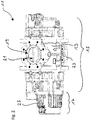
- FIG 3A shows a perspective detailed view of the motor section 17 of the vacuum pump 11.
- the motor section 17 has cooling fins 25 on its outer circumference, which are provided for cooling the electric motor, which is located in an interior of the motor section 17.
- the motor section 17 includes in an end section which is shown in FIG 3A and 3B is shown on the right, a terminal box 27, which in Figure 3A is closed by a cover 29, while the cover 29 in Figure 3B is removed.
- the motor section 17 has no cooling fins 25, since the terminal box 27 is provided for the electrical connections of the electric motor of the vacuum pump 11 and therefore does not require any cooling.
- the electric motor of the vacuum pump 11 can also be water-cooled.
- the motor section 17 has cast-in water pipes and does not require any cooling fins 25.
- connection elements 31 are arranged in the terminal box 27 of the motor section 17 and are provided for supplying the electric motor with electrical currents and voltages. Furthermore, the terminal box 27 comprises an earthing 33, which are attached to a housing wall 35 inside the terminal box 27, on which the connection elements 31 are also located.
- a circuit board 37 is also arranged, which is also attached to the housing wall or inner wall 35 of the terminal box 27.
- the circuit board 37 has a vibration sensor 39, which acts as an acceleration sensor a micro-electromechanical system (MEMS sensor) is formed.
- MEMS sensor micro-electromechanical system
- the vibration sensor 39 is in direct connection with the housing wall 35, ie there are no further elements between the vibration sensor 39 and the housing wall 35 in order to transmit vibrations of the housing 13 of the vacuum pump 11 as directly as possible to the vibration sensor 39.
- the circuit board 37 also has an evaluation unit 41 for the vibration sensor 39.
- the evaluation unit 41 comprises an integrated processor, with which the evaluation of vibration data takes place, which are recorded by means of the vibration sensor 39.
- the vibration sensor 39 and the evaluation unit 41 including the processor are thus in an electronic communication connection within the circuit board 37.
- the motor section 17 has an electrical connection 43 on its outside, to which a plug (not shown) can be attached.
- the electrical connection 43 is electrically connected both to the connection elements 31 for the electric motor of the vacuum pump 11 and to the evaluation unit 41 on the circuit board 37, in order to ensure the power supply of the electric motor and the circuit board 37 on the one hand and to establish a connection for signals from of the evaluation unit 41 are provided and represent an indicator of a state of wear of the vacuum pump 11.
- the vibration sensor 39 which is designed as a MEMS sensor, is able to measure an acceleration in all three spatial directions.
- the vibration sensor 39 thus detects vibrations in all three spatial directions.
- One of these spatial directions or axes is with an axis of rotation of the pump-active elements of the vacuum pump 11 (cf. Fig. 2 ) aligned. This makes it particularly easy to detect vibrations that occur due to the fact that the movement of the pump-active elements of an expected movement in normal operation the vacuum pump 11 deviates. This can be caused, for example, by an imbalance in the pump-active elements.
- the vibration data that are recorded by means of the vibration sensor 39 are evaluated by means of the evaluation unit 41 or by means of their processor, for example by comparing these vibration data with vibration data that were recorded at an earlier point in time and are stored in the evaluation unit 41. For example, the amplitude of the current and previous vibration data, averaged over a predetermined period of time, is compared. Alternatively, the amplitude of the recorded vibration data can also be compared with a predetermined threshold value, which is based on empirical values.
- the evaluation unit 41 If a significant deviation between the current vibration data and the stored vibration data acquired at an earlier point in time is determined or the amplitude of the vibration data lies above the predetermined threshold value, the evaluation unit 41 outputs an advisory signal which is sent to a control unit (not shown) by means of the electrical connection 43 Vacuum pump 11 is transmitted to generate a perceptible indication for a user of the vacuum system, for example by means of a warning light.
- the vibration sensor 39 is arranged on the circuit board 37, while the evaluation unit 41 is located outside the terminal box 27 and is integrated in the control unit (not shown) of the vacuum pump 11. In this case, however, the vibration sensor 39 and the evaluation unit 41 are likewise in an electronic communication connection, which takes place via the electrical connection 43.
- connection elements 31 and the circuit board 37 are not shown.
Landscapes
- Engineering & Computer Science (AREA)
- Mechanical Engineering (AREA)
- General Engineering & Computer Science (AREA)
- Applications Or Details Of Rotary Compressors (AREA)
- Compressors, Vaccum Pumps And Other Relevant Systems (AREA)
- Control Of Positive-Displacement Pumps (AREA)
Abstract
Eine Vakuumpumpe, bei der es sich beispielsweise um eine Wälzkolbenpumpe oder eine Schraubenpumpe handelt, umfasst pumpaktive Elemente, die zu einer Arbeitsbewegung antreibbar sind und ein zu pumpendes Gas von einem Einlass zu einem Auslass der Vakuumpumpe transportieren, einen Schwingungssensor, der Schwingungsdaten der Vakuumpumpe aufgrund der Arbeitsbewegung der pumpaktiven Elemente erfasst, und eine Auswerteeinheit, die ausgebildet ist, um die Schwingungsdaten auszuwerten.A vacuum pump, which is, for example, a Roots pump or a screw pump, comprises pump-active elements which can be driven to perform a working movement and transport a gas to be pumped from an inlet to an outlet of the vacuum pump, a vibration sensor, the vibration data of the vacuum pump due to the Working movement of the pump-active elements detected, and an evaluation unit which is designed to evaluate the vibration data.
Description
Die Erfindung betrifft eine Vakuumpumpe, bei der es sich insbesondere um eine Wälzkolbenpumpe oder Schraubenpumpe handelt. Die Vakuumpumpe weist pumpaktive Elemente auf, die zu einer Arbeitsbewegung antreibbar sind und die ein zu pumpendes Gas von einem Einlass zu einem Auslass der Vakuumpumpe transportieren.The invention relates to a vacuum pump, which is in particular a Roots pump or screw pump. The vacuum pump has pump-active elements which can be driven to perform a working movement and which transport a gas to be pumped from an inlet to an outlet of the vacuum pump.
Vakuumanlagen umfassen typischerweise eine oder mehrere Vakuumpumpen, beispielsweise mindestens eine Vakuumpumpe für den Grobvakuumbereich und mindestens eine Vakuumpumpe für den Hochvakuumbereich, und sind üblicherweise für einen Dauerbetrieb ausgelegt. Bei vielen Anwendungen sind die Vakuumpumpen der Vakuumanlage mehrere Monate oder sogar Jahre ununterbrochen in Betrieb. Ferner sollen Stillstandszeiten zwischen Betriebsphasen der Vakuumanlage möglichst minimiert werden, und die Wartung der Vakuumpumpen sollte innerhalb dieser relativ kurzen Stillstandszeiten erfolgen.Vacuum systems typically comprise one or more vacuum pumps, for example at least one vacuum pump for the rough vacuum range and at least one vacuum pump for the high vacuum range, and are usually designed for continuous operation. In many applications, the vacuum pumps in the vacuum system run continuously for several months or even years. In addition, downtimes between operating phases of the vacuum system are to be minimized as far as possible, and the maintenance of the vacuum pumps should take place within these relatively short downtimes.
Bei einem solchen Dauerbetrieb einer Vakuumanlage sind folglich plötzliche Ausfälle von Vakuumpumpen unerwünscht, die unbeabsichtigte Stillstandszeiten für die Vakuumanlage und die Anwendung mit sich bringen, die in dieser ausgeführt werden soll.In such a continuous operation of a vacuum system, sudden failures of vacuum pumps are consequently undesirable, which lead to unintended downtimes for the vacuum system and the application which is to be carried out in it.
Ferner ist bekannt, dass ein Zusammenhang zwischen Schwingungen von Vakuumpumpen und deren Betriebszustand bzw. Verschleißzustand besteht. Beispielsweise kann sich ein plötzlicher Ausfall einer Vakuumpumpe durch übermäßige Schwingungen oder sogar Geräusche ankündigen. Solche Schwingungen können beispielsweise durch eine Unwucht eines Rotors der Vakuumpumpe hervorgerufen werden, und eine Zunahme der Unwucht kann eine Zunahme der Schwingungen der Vakuumpumpe bewirken. Eine Überwachung von Schwingungen einer Vakuumpumpe ist jedoch bei herkömmlichen Vakuumanlagen bisher nicht vorgesehen und wird folglich nur sporadisch ausgeführt. Außerdem erfolgt eine Überwachung von Schwingungen einer Vakuumpumpe in solchen Fällen mit vergleichsweise teuren externen Einrichtungen.It is also known that there is a connection between vibrations of vacuum pumps and their operating state or state of wear. For example, a sudden failure of a vacuum pump can result from excessive vibrations or even noise. Such vibrations can be caused, for example, by an imbalance in a rotor of the vacuum pump and an increase in unbalance can cause an increase in the vibrations of the vacuum pump. Monitoring of vibrations of a vacuum pump has, however, hitherto not been provided in conventional vacuum systems and is consequently only carried out sporadically. In addition, vibrations of a vacuum pump are monitored in such cases with comparatively expensive external devices.
Eine Aufgabe der Erfindung besteht darin, eine Vakuumpumpe zu schaffen, bei der ein möglicherweise bevorstehender Ausfall frühzeitig erkannt werden kann.An object of the invention is to provide a vacuum pump in which a possibly impending failure can be recognized at an early stage.
Diese Aufgabe wird durch eine Vakuumpumpe mit den Merkmalen des Anspruchs 1 gelöst.This object is achieved by a vacuum pump with the features of claim 1.
Die Vakuumpumpe, bei der es sich insbesondere um eine Wälzkolbenpumpe oder eine Schraubenpumpe handelt, umfasst pumpaktive Elemente, die zu einer Arbeitsbewegung antreibbar sind und dadurch ein zu pumpendes Gas von einem Einlass zu einem Auslass der Vakuumpumpe transportieren. Ferner umfasst die Vakuumpumpe einen Schwingungssensor, der Schwingungsdaten der Vakuumpumpe aufgrund der Arbeitsbewegung der pumpaktiven Elemente erfasst, und eine Auswerteeinheit, die ausgebildet ist, um die Schwingungsdaten auszuwerten.The vacuum pump, which is in particular a Roots pump or a screw pump, comprises pump-active elements which can be driven to perform a working movement and thereby transport a gas to be pumped from an inlet to an outlet of the vacuum pump. Furthermore, the vacuum pump comprises a vibration sensor, which records vibration data of the vacuum pump on the basis of the working movement of the pump-active elements, and an evaluation unit, which is designed to evaluate the vibration data.
Die erfindungsgemäße Vakuumpumpe zeichnet sich dadurch aus, dass der Schwingungssensor und die Auswerteeinheit für die Schwingungsdaten, die der Schwingungssensor erfasst, wesentliche Bestandteile der Vakuumpumpe an sich sind. Zum Erfassen und Auswerten der Schwingungsdaten der Vakuumpumpe sind folglich keine teuren externen Einrichtungen erforderlich.The vacuum pump according to the invention is characterized in that the vibration sensor and the evaluation unit for the vibration data that the vibration sensor records are essential components of the vacuum pump itself. Consequently, no expensive external devices are required for recording and evaluating the vibration data of the vacuum pump.
Während der Schwingungssensor zum Erfassen der Schwingungen der Vakuumpumpe einen engen Kontakt mit einer Pumpeinheit, welche die pumpaktiven Elemente umfasst, aufweisen sollte, kann die Auswerteeinheit entweder eine gemeinsame Einheit mit dem Schwingungssensor bilden, beispielsweise in der Form einer einzigen elektronischen Einrichtung, die sowohl den Schwingungssensor als auch die Auswerteeinheit umfassen kann, oder extern angeordnet sein. In letzterem Fall kann die Auswerteeinheit ebenso wie eine Steuerungseinheit der gesamten Vakuumpumpe außerhalb eines Gehäuses der Vakuumpumpe angeordnet sein und dennoch ebenso wie die Steuerungseinheit einen wesentlichen Bestandteil der Vakuumpumpe an sich bilden. Mit anderen Worten sind der Schwingungssensor und die Auswerteeinheit unabhängig davon, ob die Auswerteeinheit innerhalb oder außerhalb des Gehäuses der Vakuumpumpe angeordnet ist, zusammen mit einer Steuerungseinheit als integrale Bestandteile der Vakuumpumpe anzusehen.While the vibration sensor for detecting the vibrations of the vacuum pump should have close contact with a pump unit that includes the pump-active elements, the evaluation unit can either have a common one Form unit with the vibration sensor, for example in the form of a single electronic device, which can include both the vibration sensor and the evaluation unit, or be arranged externally. In the latter case, the evaluation unit, like a control unit of the entire vacuum pump, can be arranged outside a housing of the vacuum pump and, like the control unit, can nevertheless form an essential component of the vacuum pump itself. In other words, the vibration sensor and the evaluation unit, regardless of whether the evaluation unit is arranged inside or outside the housing of the vacuum pump, together with a control unit, are to be regarded as integral components of the vacuum pump.
Die interne oder externe Anordnung einer Steuerungseinheit für die Vakuumpumpe und der Auswerteeinheit für die Schwingungsdaten kann beispielsweise von dem vorhandenen Bauraum für die Vakuumpumpe abhängen. Bei einer externen Anordnung der Auswerteeinheit, beispielsweise außerhalb des Gehäuses der Vakuumpumpe, kann die Auswerteeinheit in die Steuerungseinheit der Vakuumpumpe integriert sein. Unabhängig davon, ob die Auswerteeinheit mit dem Schwingungssensor eine gemeinsame elektronische Einrichtung bildet oder extern angeordnet ist, besteht zwischen der Auswerteeinheit und dem Schwingungssensor eine elektronische Kommunikationsverbindung zum Übertragen der Schwingungsdaten als Signale des Schwingungssensors an die Auswerteeinheit.The internal or external arrangement of a control unit for the vacuum pump and the evaluation unit for the vibration data can depend, for example, on the available space for the vacuum pump. With an external arrangement of the evaluation unit, for example outside the housing of the vacuum pump, the evaluation unit can be integrated into the control unit of the vacuum pump. Regardless of whether the evaluation unit forms a common electronic device with the vibration sensor or is arranged externally, there is an electronic communication connection between the evaluation unit and the vibration sensor for transmitting the vibration data as signals from the vibration sensor to the evaluation unit.
Anhand der Auswertung der Schwingungsdaten, die mittels der Auswerteeinheit erfolgt, kann ein möglicherweise bevorstehender Ausfall der Vakuumpumpe frühzeitig erkannt werden. Wenn beispielsweise die von dem Schwingungssensor gemessene Intensität der Schwingungen aufgrund einer erhöhten Amplitude der Schwingungen der Vakuumpumpe einen bestimmten Schwellenwert überschreitet, kann dies ein Indikator für einen möglicherweise bevorstehenden Ausfall der Vakuumpumpe aufgrund einer Fehlfunktion der pumpaktiven Elemente sein. In einem solchen Fall, d.h. wenn ein möglicherweise bevorstehender Ausfall der Vakuumpumpe anhand der Schwingungsdaten durch die Auswerteeinheit erkennbar ist, kann die Auswerteeinheit ein Hinweissignal erzeugen, das beispielsweise mittels einer Warnleuchte oder eines hörbaren Signals für einen Benutzer der Vakuumanlage wahrnehmbar sein kann.A potential impending failure of the vacuum pump can be recognized at an early stage on the basis of the evaluation of the vibration data, which is carried out by means of the evaluation unit. For example, if the intensity of the vibrations measured by the vibration sensor exceeds a certain threshold value due to an increased amplitude of the vibrations of the vacuum pump, this can be an indicator of a possible impending failure of the vacuum pump due to a malfunction of the pump-active elements. In one In such a case, ie if a possible impending failure of the vacuum pump can be recognized by the evaluation unit on the basis of the vibration data, the evaluation unit can generate an advisory signal which can be perceived by a user of the vacuum system, for example by means of a warning lamp or an audible signal.
Anhand der Auswertung der Schwingungsdaten mittels der Auswerteeinheit ist es folglich möglich, einen bevorstehenden Ausfall der Vakuumpumpe zu erkennen und zu verhindern, indem eine geplante Stillstandszeit der Vakuumpumpe für deren Wartung vorgesehen wird. Bezogen auf die gesamte Betriebsdauer der Vakuumpumpe bzw. Vakuumanlage lässt sich die gesamte Stillstandszeit durch die Vermeidung unvorhergesehener Ausfälle von Vakuumpumpen verkürzen. Anstelle eines unvorhergesehenen Ausfalls erfolgt stattdessen durch die Auswertung der Schwingungsdaten und das Erkennen eines bevorstehenden Ausfalls eine "Predictive Maintenance", d.h. eine geplante Stillstandszeit zur Wartung der Pumpe, die in der Regel kürzer ist als die Stillstandszeit nach einem unvorhergesehenen Ausfall.Based on the evaluation of the vibration data by means of the evaluation unit, it is consequently possible to recognize and prevent an impending failure of the vacuum pump by providing a planned downtime for the vacuum pump for its maintenance. Based on the total operating time of the vacuum pump or vacuum system, the total downtime can be shortened by avoiding unforeseen failures of the vacuum pumps. Instead of an unforeseen failure, a "predictive maintenance" takes place instead by evaluating the vibration data and recognizing an impending failure. a planned downtime for the maintenance of the pump, which is usually shorter than the downtime after an unforeseen failure.
Vorteilhafte Weiterbildungen der Erfindung sind in den Unteransprüchen, der Beschreibung und den Zeichnungen angegeben.Advantageous developments of the invention are specified in the subclaims, the description and the drawings.
Gemäß einer vorteilhaften Ausführungsform ist die Auswerteeinheit der Vakuumpumpe ferner ausgebildet, um anhand der Schwingungsdaten einen Verschleißzustand der Vakuumpumpe zu ermitteln. Die Auswerteeinheit kann beispielsweise angeben, dass ein bestimmter Verschleißzustand der Vakuumpumpe vorliegt, wenn die Intensität der Schwingungen, die durch den Schwingungssensor erfasst werden, aufgrund einer erhöhten Amplitude der Schwingungen der Vakuumpumpe einen vorgegebenen Schwellenwert überschreitet. Ein solcher vorgegebener Schwellenwert kann beispielsweise einem bestimmten Verschleißzustand der Vakuumpumpe direkt zugeordnet sein. Der vorgegebene Schwellenwert kann dabei kalibrierbar sein und auf Erfahrungswerten beruhen, beispielsweise aufgrund von Schwingungsdaten, die bei einem tatsächlichen Ausfall der Vakuumpumpe aufgezeichnet wurden. Liegt der Absolutbetrag der Schwingungsdaten oberhalb des vorbestimmten Schwellenwerts, kann die Auswerteeinheit wiederum ein Hinweissignal ausgeben, das für einen Benutzer der Vakuumanlage wahrnehmbar sein kann.According to an advantageous embodiment, the evaluation unit of the vacuum pump is also designed to determine a state of wear of the vacuum pump based on the vibration data. The evaluation unit can, for example, indicate that the vacuum pump is in a certain state of wear if the intensity of the vibrations, which are detected by the vibration sensor, exceeds a predetermined threshold value due to an increased amplitude of the vibrations of the vacuum pump. Such a predetermined threshold value can, for example, be assigned directly to a specific state of wear of the vacuum pump. The predefined threshold can be calibratable and based on empirical values, for example on the basis of vibration data which were recorded in the event of an actual failure of the vacuum pump. If the absolute amount of the vibration data is above the predetermined threshold value, the evaluation unit can in turn output an advisory signal that can be perceptible to a user of the vacuum system.
Alternativ können die Schwingungsdaten zur Ermittlung des Verschleißzustands der Vakuumkammer periodisch in vorbestimmten Zeitintervallen erfasst und gespeichert werden, und die Auswerteeinheit kann die zuletzt erfassten Schwingungsdaten mit den früher erfassten und gespeicherten Schwingungsdaten vergleichen. Sobald die Auswerteeinheit eine signifikante Abweichung zwischen den zuletzt erfassten Schwingungsdaten und den früher gespeicherten Schwingungsdaten feststellt, beispielsweise eine deutliche Zunahme der Amplitude der Schwingungen bzw. des Absolutbetrags der Schwingungsdaten, kann die Auswerteeinheit wiederum ein Hinweissignal ausgeben, das einen vordefinierten, unerwünschten Verschleißzustand der Vakuumpumpe angibt. Das Hinweissignal kann ausgegeben werden, wenn beispielsweise die mittlere Abweichung zwischen den zuletzt erfassten Schwingungsdaten und den früher erfassten, gespeicherten Schwingungsdaten einen weiteren, vorbestimmten Schwellenwert überschreitet.Alternatively, the vibration data for determining the state of wear of the vacuum chamber can be recorded and stored periodically at predetermined time intervals, and the evaluation unit can compare the vibration data last recorded with the vibration data recorded and stored earlier. As soon as the evaluation unit detects a significant deviation between the last recorded vibration data and the previously stored vibration data, for example a significant increase in the amplitude of the vibrations or the absolute amount of the vibration data, the evaluation unit can in turn output an advisory signal that indicates a predefined, undesired state of wear of the vacuum pump . The notification signal can be output if, for example, the mean deviation between the vibration data last recorded and the vibration data stored earlier exceeds a further predetermined threshold value.
Ferner kann die Auswerteeinheit alternativ oder zusätzlich auf Schwingungsdaten zugreifen, die für eine große Zahl baugleicher oder ähnlicher Vakuumpumpen erfasst und gespeichert wurden und beispielsweise in der Form einer Datenbank verfügbar sind. Die Auswerteeinheit kann in einem solchen Fall aktuelle Schwingungsdaten der Vakuumpumpe, die momentan mit dem Schwingungssensor erfasst werden, mit den gespeicherten Schwingungsdaten aus der Datenbank in Beziehung setzen. Dabei kann die Auswerteeinheit ein neuronales Netz umfassen, das mittels der früher gespeicherten Daten aus der Datenbank lernfähig ist, um anhand der mittels des Schwingungssensors aktuell erfassten Schwingungsdaten frühzeitig einen unerwünschten Verschleißzustand der Vakuumpumpe zu erkennen.Furthermore, the evaluation unit can alternatively or additionally access vibration data that have been recorded and stored for a large number of identical or similar vacuum pumps and are available, for example, in the form of a database. In such a case, the evaluation unit can relate current vibration data of the vacuum pump, which are currently detected by the vibration sensor, to the stored vibration data from the database. The evaluation unit can include a neural network that can be learned from the database using the previously stored data, in order to use the vibration data currently detected by the vibration sensor to detect an undesirable state of wear of the vacuum pump at an early stage.
Der Schwingungssensor kann einen Beschleunigungssensor umfassen, der insbesondere ein Beschleunigungssensor eines mikro-elektromechanischen Systems (MEMS-Sensor) ist. Die Verwendung eines solchen Beschleunigungssensors ermöglicht eine kostengünstige Integration eines Schwingungssensors in eine Vakuumpumpe, die gegebenenfalls auch nachträglich bei bestehenden Vakuumpumpen erfolgen kann.The vibration sensor can comprise an acceleration sensor, which is in particular an acceleration sensor of a micro-electromechanical system (MEMS sensor). The use of such an acceleration sensor enables an inexpensive integration of a vibration sensor into a vacuum pump, which can also be carried out retrospectively in existing vacuum pumps.
Der Beschleunigungssensor erfasst vorzugsweise die Beschleunigung in zumindest zwei Richtungen. Dabei ist insbesondere eine der Richtungen, in denen der Beschleunigungssensor die Beschleunigung erfasst, mit einer Rotationsachse der pumpaktiven Elemente der Vakuumpumpe ausgerichtet. Wenn der Beschleunigungssensor die Beschleunigung in zwei oder sogar drei Richtungen erfassen kann, verbessert dies die Zuverlässigkeit des Schwingungssensors, da die Erfassung der Schwingungsdaten somit nicht nur auf eine Raumrichtung festgelegt ist. Mit anderen Worten wird durch die Erfassung der Beschleunigung in zwei oder drei Raumrichtungen die Wahrscheinlichkeit verringert, dass Schwingungen der Vakuumpumpe auftreten, die durch den Schwingungssensor nicht erfasst werden können. Durch die Ausrichtung einer der Richtungen, in denen der Beschleunigungssensor die Beschleunigung erfasst, mit der Rotationsachse der pumpaktiven Elemente kann eine Änderung der Schwingungsdaten erfasst werden, welche speziell durch die pumpaktiven Elemente hervorgerufen wird. Beispielsweise kann bei einer solchen Ausrichtung des Beschleunigungssensors eine Unwucht der pumpaktiven Elemente frühzeitig erkannt werden, da die Schwingungsdaten, die der mit der Rotationsachse der pumpaktiven Elemente ausgerichtete Beschleunigungssensor erfasst, für die pumpaktiven Elemente spezifisch sind.The acceleration sensor preferably detects the acceleration in at least two directions. In particular, one of the directions in which the acceleration sensor detects the acceleration is aligned with an axis of rotation of the pump-active elements of the vacuum pump. If the acceleration sensor can detect the acceleration in two or even three directions, this improves the reliability of the vibration sensor, since the detection of the vibration data is therefore not restricted to one spatial direction. In other words, the detection of the acceleration in two or three spatial directions reduces the probability that vibrations of the vacuum pump occur which cannot be detected by the vibration sensor. By aligning one of the directions in which the acceleration sensor detects the acceleration with the axis of rotation of the pump-active elements, a change in the vibration data, which is specifically caused by the pump-active elements, can be detected. For example, with such an alignment of the acceleration sensor, an imbalance of the pump-active elements can be recognized at an early stage, since the vibration data which the acceleration sensor aligned with the axis of rotation of the pump-active elements detects are specific to the pump-active elements.
Gemäß einer weiteren Ausführungsform ist der Schwingungssensor innerhalb eines Gehäuses der Vakuumpumpe angeordnet. Der Schwingungssensor ist bei dieser Ausführungsform somit vollständig in die Vakuumpumpe integriert und innerhalb des Gehäuses vor äußeren Einflüssen geschützt. Im Vergleich zu einer Anordnung an einer Außenfläche des Gehäuses der Vakuumpumpe kann darüber hinaus der Abstand zwischen dem Schwingungssensor und den pumpaktiven Elementen innerhalb des Gehäuses möglichst gering gewählt werden, so dass die Erfassung der Schwingungsdaten aufgrund der Arbeitsbewegung der pumpaktiven Elemente verbessert ist.According to a further embodiment, the vibration sensor is arranged within a housing of the vacuum pump. In this embodiment, the vibration sensor is thus fully integrated into the vacuum pump and protected from external influences within the housing. In comparison to an arrangement on an outer surface of the housing of the vacuum pump, the distance between the vibration sensor and the pump-active elements within the housing can also be chosen to be as small as possible, so that the acquisition of the vibration data is improved due to the working movement of the pump-active elements.
Ferner kann der Schwingungssensor mit dem Gehäuse der Vakuumpumpe direkt gekoppelt sein. Wenn die pumpaktiven Elemente unerwünschte Schwingungen ausführen, werden diese meistens auf das Gehäuse der Vakuumpumpe übertragen. Bei einer direkten Kopplung des Schwingungssensors mit dem Gehäuse der Vakuumpumpe können die Schwingungsdaten der Vakuumpumpe aufgrund der Arbeitsbewegung der pumpaktiven Elemente auf besonders einfache und zuverlässige Weise erfasst werden. Bei dieser Ausführungsform kann der Schwingungssensor ferner an einer Innenwand des Gehäuses der Vakuumpumpe angebracht und mit dieser direkt gekoppelt sein, so dass der Schwingungssensor gleichzeitig innerhalb des Gehäuses der Vakuumpumpe angeordnet und mit diesem direkt gekoppelt sein kann.Furthermore, the vibration sensor can be directly coupled to the housing of the vacuum pump. If the pump-active elements cause undesired vibrations, these are usually transmitted to the housing of the vacuum pump. With a direct coupling of the vibration sensor to the housing of the vacuum pump, the vibration data of the vacuum pump can be recorded in a particularly simple and reliable manner due to the working movement of the pump-active elements. In this embodiment, the vibration sensor can also be attached to an inner wall of the housing of the vacuum pump and can be directly coupled to it, so that the vibration sensor can simultaneously be arranged within the housing of the vacuum pump and can be directly coupled to it.
Darüber hinaus kann der Schwingungssensor in eine Platine der Vakuumpumpe integriert sein. Dabei ist die Platine insbesondere in einem Innenraum der Vakuumpumpe angeordnet. Bei dieser Ausführungsform kann der Schwingungssensor insbesondere lediglich einen weiteren Baustein einer bereits vorhandenen Platine der Vakuumpumpe darstellen, so dass der Schwingungssensor auf einfache und kostengünstige Weise in die Vakuumpumpe integriert werden kann. Wenn die Platine im Innenraum der Vakuumpumpe angeordnet ist, kann die Platine darüber hinaus gleichzeitig eine Vakuumdurchführung darstellen.In addition, the vibration sensor can be integrated in a circuit board of the vacuum pump. The circuit board is arranged in particular in an interior of the vacuum pump. In this embodiment, the vibration sensor can, in particular, only represent a further component of an existing circuit board of the vacuum pump, so that the vibration sensor can be integrated into the vacuum pump in a simple and inexpensive manner. If the circuit board is arranged in the interior of the vacuum pump, the circuit board can also simultaneously represent a vacuum feedthrough.
Die Platine ist bevorzugt in einer Antriebselektronik eines Antriebsmotors der Vakuumpumpe integriert. Dabei kann die Platine insbesondere in einem sogenannten Klemmkasten des Antriebsmotors der Vakuumpumpe angeordnet sein. Zusätzlich kann die Auswerteeinheit in die Platine der Vakuumpumpe integriert sein. Bei diesen Ausführungsformen kann ungenutzter Bauraum innerhalb der Vakuumpumpe, beispielsweise im Klemmkasten des Antriebsmotors, zur Integration des Schwingungssensors und/oder der Auswerteeinheit ausgenutzt werden. Wenn sowohl der Schwingungssensor als auch die Auswerteeinheit auf der Platine der Vakuumpumpe angeordnet bzw. in diese integriert sind, bilden der Schwingungssensor und die Auswerteeinheit eine besonders kompakte Einheit, die bereits ausgewertete Schwingungsdaten ausgibt, beispielsweise mittels eines Signals, das den Verschleißzustand der Vakuumpumpe angibt.The circuit board is preferably integrated in a drive electronics of a drive motor of the vacuum pump. The circuit board can in particular be arranged in a so-called terminal box of the drive motor of the vacuum pump. In addition, the evaluation unit can be integrated in the circuit board of the vacuum pump. In these embodiments, unused space within the vacuum pump, for example in the terminal box of the drive motor, can be used to integrate the vibration sensor and / or the evaluation unit. If both the vibration sensor and the evaluation unit are arranged on the circuit board of the vacuum pump or are integrated in the latter, the vibration sensor and the evaluation unit form a particularly compact unit that outputs vibration data that has already been evaluated, for example by means of a signal that indicates the state of wear of the vacuum pump.
Die Auswerteeinheit kann ferner einen integrierten Prozessor aufweisen, der ausgebildet ist, um die Schwingungsdaten einem Verschleißzustand der Vakuumpumpe zuzuordnen. Die Auswertung der Schwingungsdaten erfolgt somit bereits vollständig in dem integrierten Prozessor der Auswerteeinheit, die zudem in die Platine der Vakuumpumpe integriert ist. Dadurch kann die Auswerteeinheit wiederum zusammen mit dem Schwingungssensor eine kompakte Einheit bilden, selbst wenn dieser außerhalb der Platine an einem Abschnitt des Gehäuses der Vakuumpumpe angebracht ist.The evaluation unit can also have an integrated processor which is designed to assign the vibration data to a state of wear of the vacuum pump. The vibration data is therefore fully evaluated in the integrated processor of the evaluation unit, which is also integrated in the circuit board of the vacuum pump. As a result, the evaluation unit can in turn form a compact unit together with the vibration sensor, even if it is attached to a section of the housing of the vacuum pump outside the circuit board.
Gemäß einer weiteren Ausführungsform umfasst die Vakuumpumpe eine Schnittstelle zur Ausgabe der Schwingungsdaten. Die Auswerteeinheit ist dabei bevorzugt außerhalb eines Gehäuses der Vakuumpumpe angeordnet, um die Schwingungsdaten mittels der Schnittstelle zu empfangen. Diese Ausführungsform stellt somit eine Alternative zur Integration der Auswerteeinheit in die Platine der Vakuumpumpe dar. Die Anordnung der Auswerteeinheit außerhalb des Gehäuses der Vakuumpumpe gestattet eine flexible Anordnung des Schwingungssensors beispielsweise an oder in dem Gehäuse der Vakuumpumpe, so dass die von diesem erfassten Schwingungsdaten lediglich über die Schnittstelle für die Auswerteeinheit bereitgestellt werden müssen.According to a further embodiment, the vacuum pump has an interface for outputting the vibration data. The evaluation unit is preferably arranged outside a housing of the vacuum pump in order to receive the vibration data via the interface. This embodiment thus represents an alternative to integrating the evaluation unit into the circuit board of the vacuum pump. The arrangement of the evaluation unit outside the housing of the vacuum pump allows, for example, a flexible arrangement of the vibration sensor on or in the housing of the vacuum pump, so that the vibration data recorded by it only have to be made available to the evaluation unit via the interface.
Gemäß einer noch weiteren Ausführungsform können der Schwingungssensor und die Auswerteeinheit mit integriertem Prozessor in eine Platine der Vakuumpumpe integriert sein, die beispielsweise in einem Klemmkasten eines Antriebsmotors innerhalb eines Gehäuses der Vakuumpumpe angeordnet ist, und es kann gleichzeitig eine Schnittstelle der Vakuumpumpe vorgesehen sein. Die Schnittstelle kann zur Ausgabe der Schwingungsdaten und zusätzlich zur Ausgabe von Daten dienen, die mittels der Auswerteeinheit ausgewertet sind und einen Verschleißzustand der Vakuumpumpe angeben. Die zusätzliche Ausgabe der ursprünglichen Schwingungsdaten, die mittels des Schwingungssensors erfasst werden, kann zusätzlich eine externe, redundante Auswertung der Schwingungsdaten ermöglichen. Durch einen Vergleich mit der Ausgabe der internen Auswerteeinheit kann die Zuverlässigkeit der Auswerteeinheit überprüft und somit verbessert werden.According to yet another embodiment, the vibration sensor and the evaluation unit with an integrated processor can be integrated in a circuit board of the vacuum pump, which is arranged, for example, in a terminal box of a drive motor within a housing of the vacuum pump, and an interface of the vacuum pump can be provided at the same time. The interface can be used to output the vibration data and also to output data that are evaluated by the evaluation unit and indicate a state of wear of the vacuum pump. The additional output of the original vibration data, which is recorded by means of the vibration sensor, can additionally enable an external, redundant evaluation of the vibration data. The reliability of the evaluation unit can be checked and thus improved by a comparison with the output of the internal evaluation unit.
Die Erfindung wird nachfolgend rein beispielhaft anhand möglicher Ausführungsformen der Erfindung unter Bezugnahme auf die beigefügten Figuren erläutert. Es zeigen:
- Fig. 1
- eine schematische Perspektivansicht einer erfindungsgemäßen Vakuumpumpe,
- Fig. 2
- eine weitere schematische Perspektivansicht von oben auf die Vakuumpumpe von
Fig. 1 , - Fig. 3A und 3B
- jeweils eine schematische Perspektivansicht eines Motorabschnitts der Vakuumpumpe von
Fig. 1 und2 , und - Fig. 4
- eine vergrößerte Draufsicht auf den Motorabschnitt der erfindungsgemäßen Vakuumpumpe.
- Fig. 1
- 2 shows a schematic perspective view of a vacuum pump according to the invention,
- Fig. 2
- another schematic perspective view from above of the vacuum pump of
Fig. 1 , - 3A and 3B
- each a schematic perspective view of a motor section of the vacuum pump of FIG
Fig. 1 and2nd , and - Fig. 4
- an enlarged plan view of the motor section of the vacuum pump according to the invention.
Der Hauptabschnitt 15 des Gehäuses 13 der Vakuumpumpe 11 weist einen Ansaugflansch 19 auf, der als Einlass für ein zu pumpendes Gas dient, das aus einem nicht dargestellten Rezipienten angesaugt wird. Zwischen dem Rezipienten und der Vakuumpumpe 11 ist innerhalb einer Vakuumanlage üblicherweise mindestens eine weitere Vakuumpumpe, beispielsweise eine Turbomolekularpumpe (nicht dargestellt) angeordnet. Ferner benötigt die als Wälzkolbenpumpe ausgebildete Vakuumpumpe 11 eine Vorpumpe, die mit dem Auslass 23 der Vakuumpumpe 11 verbunden ist und gegen Atmosphärendruck ausstößt. Somit befindet sich die Vakuumpumpe 11 in einer Vakuumanlage üblicherweise zwischen einer Pumpe für den Hochvakuumbereich, beispielsweise einer Turbomolekularpumpe, und der gegen Atmosphärendruck ausstoßenden Vorpumpe.The
Die Vakuumpumpe 11 weist außerdem pumpaktive Elemente (nicht dargestellt) in der Form von Wälzkolben auf, die in einem Innenraum 21 (vgl.
Wie in
In dem Klemmkasten 27 ist außerdem eine Platine 37 angeordnet, die ebenfalls an der Gehäusewand bzw. Innenwand 35 des Klemmkastens 27 angebracht ist. Die Platine 37 weist einen Schwingungssensor 39 auf, der als ein Beschleunigungssensor eines mikro-elektromechanischen Systems (MEMS-Sensor) ausgebildet ist. Der Schwingungssensor 39 steht mit der Gehäusewand 35 in direkter Verbindung, d.h. es befinden sich keine weiteren Elemente zwischen dem Schwingungssensor 39 und der Gehäusewand 35, um Schwingungen des Gehäuses 13 der Vakuumpumpe 11 möglichst direkt auf den Schwingungssensor 39 zu übertragen.In the
Die Platine 37 weist ferner eine Auswerteeinheit 41 für den Schwingungssensor 39 auf. Die Auswerteeinheit 41 umfasst einen integrierten Prozessor, mit dem die Auswertung von Schwingungsdaten erfolgt, die mittels des Schwingungssensors 39 erfasst werden. Der Schwingungssensor 39 und die Auswerteeinheit 41 einschließlich des Prozessors stehen somit in einer elektronischen Kommunikationsverbindung innerhalb der Platine 37.The
Außerdem weist der Motorabschnitt 17 an seiner Außenseite einen elektrischen Anschluss 43 auf, an dem ein nicht dargestellter Stecker angebracht werden kann. Der elektrische Anschluss 43 ist sowohl mit den Anschlusselementen 31 für den Elektromotor der Vakuumpumpe 11 als auch mit der Auswerteeinheit 41 auf der Platine 37 elektrisch verbunden, um einerseits die Stromversorgung des Elektromotors und der Platine 37 sicherzustellen und andererseits eine Verbindung für Signale herzustellen, die von der Auswerteeinheit 41 bereitgestellt werden und einen Indikator für einen Verschleißzustand der Vakuumpumpe 11 darstellen.In addition, the
Der Schwingungssensor 39, der als MEMS-Sensor ausgebildet ist, ist in der Lage, eine Beschleunigung in allen drei Raumrichtungen zu messen. Somit erfasst der Schwingungssensor 39 Schwingungen in allen drei Raumrichtungen. Dabei ist eine dieser Raumrichtungen bzw. Achsen mit einer Drehachse der pumpaktiven Elemente der Vakuumpumpe 11 (vgl.
Die Schwingungsdaten, die mittels des Schwingungssensors 39 erfasst werden, werden mittels der Auswerteeinheit 41 bzw. mittels deren Prozessor ausgewertet, indem diese Schwingungsdaten beispielsweise mit Schwingungsdaten verglichen werden, die zu einem früheren Zeitpunkt erfasst wurden und in der Auswerteeinheit 41 gespeichert sind. Dabei wird beispielsweise die Amplitude der aktuellen und früheren Schwingungsdaten, gemittelt über einen vorbestimmten Zeitraum, verglichen. Alternativ kann die Amplitude der erfassten Schwingungsdaten auch mit einem vorbestimmten Schwellenwert verglichen werden, der auf Erfahrungswerten beruht. Wird eine signifikante Abweichung zwischen den aktuellen Schwingungsdaten und den gespeicherten, zu einem früheren Zeitpunkt erfassten Schwingungsdaten ermittelt oder liegt die Amplitude der Schwingungsdaten oberhalb des vorbestimmten Schwellenwerts, gibt die Auswerteeinheit 41 ein Hinweissignal aus, das mittels des elektrischen Anschlusses 43 an eine nicht dargestellte Steuerungseinheit der Vakuumpumpe 11 übertragen wird, um einen wahrnehmbaren Hinweis für einen Nutzer der Vakuumanlage zu erzeugen, beispielsweise mittels einer Warnleuchte.The vibration data that are recorded by means of the
Bei einer alternativen Ausführungsform ist auf der Platine 37 lediglich der Schwingungssensor 39 angeordnet, während sich die Auswerteeinheit 41 außerhalb des Klemmkastens 27 befindet und in die Steuerungseinheit (nicht dargestellt) der Vakuumpumpe 11 integriert ist. Dabei stehen der Schwingungssensor 39 und die Auswerteeinheit 41 jedoch ebenfalls in einer elektronischen Kommunikationsverbindung, die über den elektrischen Anschluss 43 erfolgt.In an alternative embodiment, only the
Bei sämtlichen Ausführungsformen sind zwischen dem elektrischen Anschluss 43 und den Anschlusselementen 31 sowie der Platine 37 geeignete Kabelverbindungen vorgesehen, die der Übersichtlichkeit halber in
Da anhand der Schwingungsdaten, die mittels des Schwingungssensors 39 erfasst werden, bei sämtlichen Ausführungsformen letztlich ein Signal erzeugt wird, das einem Verschleißzustand der Vakuumpumpe 11 entspricht, kann ein möglicherweise bevorstehender Ausfall der Vakuumpumpe 11 frühzeitig erkannt werden. Ist dies der Fall, kann zu einem geeigneten Zeitpunkt eine geplante Wartung der Vakuumpumpe 11 durchgeführt werden, so dass ein unerwünschter und unvorhergesehener Ausfall der Vakuumpumpe 11 verhindert werden kann.Since, based on the vibration data, which is detected by means of the
- 1111
- Vakuumpumpe, WälzkolbenpumpeVacuum pump, Roots pump
- 1313
- Gehäusecasing
- 1515
- HauptabschnittMain section
- 1717th
- MotorabschnittEngine section
- 1818th
- Schraubescrew
- 1919th
- Ansaugflansch, EinlassIntake flange, inlet
- 2121
- Innenrauminner space
- 2323
- AuslassOutlet
- 2525th
- KühlrippeCooling fin
- 2727
- KlemmkastenTerminal box
- 2929
- Deckelcover
- 3131
- AnschlusselementConnecting element
- 3333
- ErdungGrounding
- 3535
- GehäusewandHousing wall
- 3737
- Platinecircuit board
- 3939
- Schwingungssensor, MEMS-SensorVibration sensor, MEMS sensor
- 4141
- AuswerteeinheitEvaluation unit
- 4343
- elektrischer Anschlusselectrical connection
Claims (15)
wobei die Auswerteeinheit (41) ferner ausgebildet ist, um anhand der Schwingungsdaten einen Verschleißzustand der Vakuumpumpe (11) zu ermitteln.Vacuum pump (11) according to claim 1,
wherein the evaluation unit (41) is also designed to determine a state of wear of the vacuum pump (11) based on the vibration data.
wobei der Schwingungssensor (39) einen Beschleunigungssensor umfasst.Vacuum pump (11) according to claim 1 or 2,
wherein the vibration sensor (39) comprises an acceleration sensor.
wobei der Beschleunigungssensor ein Beschleunigungssensor eines mikro-elektromechanischen Systems (MEMS-Sensor) ist.Vacuum pump (11) according to claim 3,
wherein the acceleration sensor is an acceleration sensor of a micro-electromechanical system (MEMS sensor).
wobei der Beschleunigungssensor die Beschleunigung in zumindest zwei Richtungen erfasst.Vacuum pump (11) according to claim 3 or 4,
wherein the acceleration sensor detects the acceleration in at least two directions.
wobei eine der Richtungen, in denen der Beschleunigungssensor die Beschleunigung erfasst, mit einer Rotationsachse der pumpaktiven Elemente der Vakuumpumpe (11) ausgerichtet ist.Vacuum pump (11) according to claim 5,
wherein one of the directions in which the acceleration sensor detects the acceleration is aligned with an axis of rotation of the pump-active elements of the vacuum pump (11).
wobei der Schwingungssensor (39) innerhalb eines Gehäuses (13) der Vakuumpumpe (11) angeordnet ist.Vacuum pump (11) according to one of the preceding claims,
wherein the vibration sensor (39) is arranged within a housing (13) of the vacuum pump (11).
wobei der Schwingungssensor (39) mit einem Gehäuse (13) der Vakuumpumpe (11) direkt gekoppelt ist.Vacuum pump (11) according to one of the preceding claims,
wherein the vibration sensor (39) is directly coupled to a housing (13) of the vacuum pump (11).
wobei der Schwingungssensor (39) in eine Platine (37) der Vakuumpumpe (11) integriert ist, wobei die Platine (37) insbesondere in einem Innenraum der Vakuumpumpe (11) angeordnet ist.Vacuum pump (11) according to one of the preceding claims,
wherein the vibration sensor (39) is integrated in a circuit board (37) of the vacuum pump (11), the circuit board (37) being arranged in particular in an interior of the vacuum pump (11).
wobei die Platine (37) in eine Antriebselektronik eines Antriebsmotors der Vakuumpumpe (11) integriert ist.Vacuum pump (11) according to claim 9,
the circuit board (37) being integrated in a drive electronics of a drive motor of the vacuum pump (11).
wobei die Platine (37) in einem Klemmkasten (27) des Antriebsmotors der Vakuumpumpe (11) angeordnet ist.Vacuum pump (11) according to claim 9 or 10,
the circuit board (37) being arranged in a terminal box (27) of the drive motor of the vacuum pump (11).
wobei die Auswerteeinheit (41) in die Platine (37) der Vakuumpumpe (11) integriert ist.Vacuum pump (11) according to one of claims 9 to 11,
the evaluation unit (41) being integrated in the circuit board (37) of the vacuum pump (11).
wobei die Auswerteeinheit (41) einen integrierten Prozessor aufweist, der ausgebildet ist, um die Schwingungsdaten einem Verschleißzustand der Vakuumpumpe (11) zuzuordnen.Vacuum pump (11) according to claim 12,
wherein the evaluation unit (41) has an integrated processor which is designed to assign the vibration data to a state of wear of the vacuum pump (11).
ferner mit einer Schnittstelle zur Ausgabe der Schwingungsdaten.Vacuum pump (11) according to one of claims 1 to 12,
also with an interface for output of the vibration data.
wobei die Auswerteeinheit (41) außerhalb eines Gehäuses (13) der Vakuumpumpe angeordnet ist und die Schwingungsdaten mittels der Schnittstelle empfängt.Vacuum pump (11) according to claim 14,
the evaluation unit (41) being arranged outside a housing (13) of the vacuum pump and receiving the vibration data via the interface.
Priority Applications (4)
| Application Number | Priority Date | Filing Date | Title |
|---|---|---|---|
| EP20166248.3A EP3686432B1 (en) | 2020-03-27 | 2020-03-27 | Vacuum pump |
| EP21161837.6A EP3808988B1 (en) | 2020-03-27 | 2021-03-10 | Vacuum pump and method for monitoring a vacuum pump |
| JP2021040051A JP7160978B2 (en) | 2020-03-27 | 2021-03-12 | Vacuum pump and method of monitoring vacuum pump |
| CN202110336661.1A CN113446243A (en) | 2020-03-27 | 2021-03-29 | Vacuum pump and method for monitoring a vacuum pump |
Applications Claiming Priority (1)
| Application Number | Priority Date | Filing Date | Title |
|---|---|---|---|
| EP20166248.3A EP3686432B1 (en) | 2020-03-27 | 2020-03-27 | Vacuum pump |
Publications (2)
| Publication Number | Publication Date |
|---|---|
| EP3686432A1 true EP3686432A1 (en) | 2020-07-29 |
| EP3686432B1 EP3686432B1 (en) | 2022-06-08 |
Family
ID=70056901
Family Applications (1)
| Application Number | Title | Priority Date | Filing Date |
|---|---|---|---|
| EP20166248.3A Active EP3686432B1 (en) | 2020-03-27 | 2020-03-27 | Vacuum pump |
Country Status (1)
| Country | Link |
|---|---|
| EP (1) | EP3686432B1 (en) |
Cited By (2)
| Publication number | Priority date | Publication date | Assignee | Title |
|---|---|---|---|---|
| EP3736447A1 (en) * | 2020-04-17 | 2020-11-11 | Pfeiffer Vacuum Technology AG | Vacuum pump and method for monitoring a vacuum pump |
| EP3808988A3 (en) * | 2020-03-27 | 2021-06-09 | Pfeiffer Vacuum Technology AG | Vacuum pump and method for monitoring a vacuum pump |
Citations (4)
| Publication number | Priority date | Publication date | Assignee | Title |
|---|---|---|---|---|
| DE202015003927U1 (en) * | 2015-05-29 | 2015-07-13 | Oerlikon Leybold Vacuum Gmbh | Control electronics for a vacuum pump and vacuum pump |
| WO2017140471A1 (en) * | 2016-02-19 | 2017-08-24 | Multivac Sepp Haggenmüller Se & Co. Kg | Vacuum pump |
| GB2551337A (en) * | 2016-06-13 | 2017-12-20 | Edwards Ltd | Pump assembly, method and computer program |
| WO2020025754A1 (en) * | 2018-08-01 | 2020-02-06 | Leybold Gmbh | Vacuum pump |
Family Cites Families (2)
| Publication number | Priority date | Publication date | Assignee | Title |
|---|---|---|---|---|
| US5975854A (en) | 1997-05-09 | 1999-11-02 | Copeland Corporation | Compressor with protection module |
| JP7006520B2 (en) | 2018-06-14 | 2022-01-24 | 株式会社島津製作所 | Vacuum pump and diagnostic system |
-
2020
- 2020-03-27 EP EP20166248.3A patent/EP3686432B1/en active Active
Patent Citations (4)
| Publication number | Priority date | Publication date | Assignee | Title |
|---|---|---|---|---|
| DE202015003927U1 (en) * | 2015-05-29 | 2015-07-13 | Oerlikon Leybold Vacuum Gmbh | Control electronics for a vacuum pump and vacuum pump |
| WO2017140471A1 (en) * | 2016-02-19 | 2017-08-24 | Multivac Sepp Haggenmüller Se & Co. Kg | Vacuum pump |
| GB2551337A (en) * | 2016-06-13 | 2017-12-20 | Edwards Ltd | Pump assembly, method and computer program |
| WO2020025754A1 (en) * | 2018-08-01 | 2020-02-06 | Leybold Gmbh | Vacuum pump |
Cited By (2)
| Publication number | Priority date | Publication date | Assignee | Title |
|---|---|---|---|---|
| EP3808988A3 (en) * | 2020-03-27 | 2021-06-09 | Pfeiffer Vacuum Technology AG | Vacuum pump and method for monitoring a vacuum pump |
| EP3736447A1 (en) * | 2020-04-17 | 2020-11-11 | Pfeiffer Vacuum Technology AG | Vacuum pump and method for monitoring a vacuum pump |
Also Published As
| Publication number | Publication date |
|---|---|
| EP3686432B1 (en) | 2022-06-08 |
Similar Documents
| Publication | Publication Date | Title |
|---|---|---|
| EP3686432B1 (en) | Vacuum pump | |
| EP1272380B1 (en) | System and device for detecting yawing movements using redundant measuring channels | |
| DE69623312T2 (en) | Warehouse and warehouse monitoring system | |
| EP1564411B2 (en) | Method for detecting operation errors of a pump aggregate | |
| EP2072829B1 (en) | Immersion pump | |
| DE112007000400T5 (en) | Fault diagnostic system in a load drive assembly and fuel pump control system | |
| EP1502086A2 (en) | Vibration sensor and method for monitoring the condition of rotating components and bearings | |
| WO2008116538A1 (en) | Method for the detection of errors in pump units | |
| WO2020015794A1 (en) | Method and system for evaluating the vibration behavior of an electric motor | |
| DE112013002268T5 (en) | Filters, filter assemblies, filter systems and methods for detecting the incorporation of qualified filter elements | |
| DE102017115625A1 (en) | A motor having a function for generating and supplying electrical energy at a coil end portion | |
| WO2015067497A2 (en) | Electric machine | |
| DE102018125969A1 (en) | Mechanical seal device with microsystem, pump device herewith and method for its operation | |
| EP2426360A2 (en) | Pump assembly with integrated vibration measurement | |
| DE102018211833A1 (en) | Sensor arrangement for detecting operating parameters of an electric motor and corresponding electric motor | |
| WO2022223082A1 (en) | Method for assessing the vibration behaviour of an electric motor, and corresponding electric motor and fan | |
| DE102013202301B4 (en) | Fault isolation in an electronic fuel system without feedback | |
| WO2019223882A1 (en) | Electrical drive device with condition monitoring | |
| DE202021101831U1 (en) | Electric pump | |
| EP0815511B1 (en) | Method and device for monitoring an electronic computing unit | |
| DE102009015711A1 (en) | Monitoring a microgenerator circuit of a rotary encoder device | |
| DE602004004778T2 (en) | SENSOR ASSEMBLY, FLUID PUMP AND COOLER | |
| EP3543537A1 (en) | Pump unit and method for monitoring the liquid situation in a seal assembly in a pump unit | |
| DE102021006193A1 (en) | Sensor and method for monitoring an electrically operated drive system using a sensor | |
| DE10040511A1 (en) | Automobile safety-critical measurement detection system has at least 2 independent measuring channels provided with independent sensors |
Legal Events
| Date | Code | Title | Description |
|---|---|---|---|
| PUAI | Public reference made under article 153(3) epc to a published international application that has entered the european phase |
Free format text: ORIGINAL CODE: 0009012 |
|
| STAA | Information on the status of an ep patent application or granted ep patent |
Free format text: STATUS: THE APPLICATION HAS BEEN PUBLISHED |
|
| AK | Designated contracting states |
Kind code of ref document: A1 Designated state(s): AL AT BE BG CH CY CZ DE DK EE ES FI FR GB GR HR HU IE IS IT LI LT LU LV MC MK MT NL NO PL PT RO RS SE SI SK SM TR |
|
| AX | Request for extension of the european patent |
Extension state: BA ME |
|
| STAA | Information on the status of an ep patent application or granted ep patent |
Free format text: STATUS: REQUEST FOR EXAMINATION WAS MADE |
|
| 17P | Request for examination filed |
Effective date: 20210127 |
|
| RBV | Designated contracting states (corrected) |
Designated state(s): AL AT BE BG CH CY CZ DE DK EE ES FI FR GB GR HR HU IE IS IT LI LT LU LV MC MK MT NL NO PL PT RO RS SE SI SK SM TR |
|
| STAA | Information on the status of an ep patent application or granted ep patent |
Free format text: STATUS: EXAMINATION IS IN PROGRESS |
|
| 17Q | First examination report despatched |
Effective date: 20210419 |
|
| GRAP | Despatch of communication of intention to grant a patent |
Free format text: ORIGINAL CODE: EPIDOSNIGR1 |
|
| STAA | Information on the status of an ep patent application or granted ep patent |
Free format text: STATUS: GRANT OF PATENT IS INTENDED |
|
| INTG | Intention to grant announced |
Effective date: 20220224 |
|
| GRAS | Grant fee paid |
Free format text: ORIGINAL CODE: EPIDOSNIGR3 |
|
| GRAA | (expected) grant |
Free format text: ORIGINAL CODE: 0009210 |
|
| STAA | Information on the status of an ep patent application or granted ep patent |
Free format text: STATUS: THE PATENT HAS BEEN GRANTED |
|
| AK | Designated contracting states |
Kind code of ref document: B1 Designated state(s): AL AT BE BG CH CY CZ DE DK EE ES FI FR GB GR HR HU IE IS IT LI LT LU LV MC MK MT NL NO PL PT RO RS SE SI SK SM TR |
|
| REG | Reference to a national code |
Ref country code: AT Ref legal event code: REF Ref document number: 1497101 Country of ref document: AT Kind code of ref document: T Effective date: 20220615 Ref country code: CH Ref legal event code: EP |
|
| REG | Reference to a national code |
Ref country code: DE Ref legal event code: R096 Ref document number: 502020001187 Country of ref document: DE |
|
| REG | Reference to a national code |
Ref country code: IE Ref legal event code: FG4D Free format text: LANGUAGE OF EP DOCUMENT: GERMAN |
|
| REG | Reference to a national code |
Ref country code: LT Ref legal event code: MG9D |
|
| REG | Reference to a national code |
Ref country code: NL Ref legal event code: MP Effective date: 20220608 |
|
| PG25 | Lapsed in a contracting state [announced via postgrant information from national office to epo] |
Ref country code: SE Free format text: LAPSE BECAUSE OF FAILURE TO SUBMIT A TRANSLATION OF THE DESCRIPTION OR TO PAY THE FEE WITHIN THE PRESCRIBED TIME-LIMIT Effective date: 20220608 Ref country code: NO Free format text: LAPSE BECAUSE OF FAILURE TO SUBMIT A TRANSLATION OF THE DESCRIPTION OR TO PAY THE FEE WITHIN THE PRESCRIBED TIME-LIMIT Effective date: 20220908 Ref country code: LT Free format text: LAPSE BECAUSE OF FAILURE TO SUBMIT A TRANSLATION OF THE DESCRIPTION OR TO PAY THE FEE WITHIN THE PRESCRIBED TIME-LIMIT Effective date: 20220608 Ref country code: HR Free format text: LAPSE BECAUSE OF FAILURE TO SUBMIT A TRANSLATION OF THE DESCRIPTION OR TO PAY THE FEE WITHIN THE PRESCRIBED TIME-LIMIT Effective date: 20220608 Ref country code: GR Free format text: LAPSE BECAUSE OF FAILURE TO SUBMIT A TRANSLATION OF THE DESCRIPTION OR TO PAY THE FEE WITHIN THE PRESCRIBED TIME-LIMIT Effective date: 20220909 Ref country code: FI Free format text: LAPSE BECAUSE OF FAILURE TO SUBMIT A TRANSLATION OF THE DESCRIPTION OR TO PAY THE FEE WITHIN THE PRESCRIBED TIME-LIMIT Effective date: 20220608 Ref country code: ES Free format text: LAPSE BECAUSE OF FAILURE TO SUBMIT A TRANSLATION OF THE DESCRIPTION OR TO PAY THE FEE WITHIN THE PRESCRIBED TIME-LIMIT Effective date: 20220608 Ref country code: BG Free format text: LAPSE BECAUSE OF FAILURE TO SUBMIT A TRANSLATION OF THE DESCRIPTION OR TO PAY THE FEE WITHIN THE PRESCRIBED TIME-LIMIT Effective date: 20220908 |
|
| PG25 | Lapsed in a contracting state [announced via postgrant information from national office to epo] |
Ref country code: RS Free format text: LAPSE BECAUSE OF FAILURE TO SUBMIT A TRANSLATION OF THE DESCRIPTION OR TO PAY THE FEE WITHIN THE PRESCRIBED TIME-LIMIT Effective date: 20220608 Ref country code: LV Free format text: LAPSE BECAUSE OF FAILURE TO SUBMIT A TRANSLATION OF THE DESCRIPTION OR TO PAY THE FEE WITHIN THE PRESCRIBED TIME-LIMIT Effective date: 20220608 |
|
| PG25 | Lapsed in a contracting state [announced via postgrant information from national office to epo] |
Ref country code: NL Free format text: LAPSE BECAUSE OF FAILURE TO SUBMIT A TRANSLATION OF THE DESCRIPTION OR TO PAY THE FEE WITHIN THE PRESCRIBED TIME-LIMIT Effective date: 20220608 |
|
| PG25 | Lapsed in a contracting state [announced via postgrant information from national office to epo] |
Ref country code: SM Free format text: LAPSE BECAUSE OF FAILURE TO SUBMIT A TRANSLATION OF THE DESCRIPTION OR TO PAY THE FEE WITHIN THE PRESCRIBED TIME-LIMIT Effective date: 20220608 Ref country code: SK Free format text: LAPSE BECAUSE OF FAILURE TO SUBMIT A TRANSLATION OF THE DESCRIPTION OR TO PAY THE FEE WITHIN THE PRESCRIBED TIME-LIMIT Effective date: 20220608 Ref country code: RO Free format text: LAPSE BECAUSE OF FAILURE TO SUBMIT A TRANSLATION OF THE DESCRIPTION OR TO PAY THE FEE WITHIN THE PRESCRIBED TIME-LIMIT Effective date: 20220608 Ref country code: PT Free format text: LAPSE BECAUSE OF FAILURE TO SUBMIT A TRANSLATION OF THE DESCRIPTION OR TO PAY THE FEE WITHIN THE PRESCRIBED TIME-LIMIT Effective date: 20221010 Ref country code: EE Free format text: LAPSE BECAUSE OF FAILURE TO SUBMIT A TRANSLATION OF THE DESCRIPTION OR TO PAY THE FEE WITHIN THE PRESCRIBED TIME-LIMIT Effective date: 20220608 |
|
| PG25 | Lapsed in a contracting state [announced via postgrant information from national office to epo] |
Ref country code: PL Free format text: LAPSE BECAUSE OF FAILURE TO SUBMIT A TRANSLATION OF THE DESCRIPTION OR TO PAY THE FEE WITHIN THE PRESCRIBED TIME-LIMIT Effective date: 20220608 Ref country code: IS Free format text: LAPSE BECAUSE OF FAILURE TO SUBMIT A TRANSLATION OF THE DESCRIPTION OR TO PAY THE FEE WITHIN THE PRESCRIBED TIME-LIMIT Effective date: 20221008 |
|
| REG | Reference to a national code |
Ref country code: DE Ref legal event code: R026 Ref document number: 502020001187 Country of ref document: DE |
|
| PLBI | Opposition filed |
Free format text: ORIGINAL CODE: 0009260 |
|
| PLAX | Notice of opposition and request to file observation + time limit sent |
Free format text: ORIGINAL CODE: EPIDOSNOBS2 |
|
| PG25 | Lapsed in a contracting state [announced via postgrant information from national office to epo] |
Ref country code: AL Free format text: LAPSE BECAUSE OF FAILURE TO SUBMIT A TRANSLATION OF THE DESCRIPTION OR TO PAY THE FEE WITHIN THE PRESCRIBED TIME-LIMIT Effective date: 20220608 |
|
| 26 | Opposition filed |
Opponent name: EDWARDS LIMITED Effective date: 20230307 |
|
| PG25 | Lapsed in a contracting state [announced via postgrant information from national office to epo] |
Ref country code: DK Free format text: LAPSE BECAUSE OF FAILURE TO SUBMIT A TRANSLATION OF THE DESCRIPTION OR TO PAY THE FEE WITHIN THE PRESCRIBED TIME-LIMIT Effective date: 20220608 |
|
| PG25 | Lapsed in a contracting state [announced via postgrant information from national office to epo] |
Ref country code: SI Free format text: LAPSE BECAUSE OF FAILURE TO SUBMIT A TRANSLATION OF THE DESCRIPTION OR TO PAY THE FEE WITHIN THE PRESCRIBED TIME-LIMIT Effective date: 20220608 |
|
| PLBB | Reply of patent proprietor to notice(s) of opposition received |
Free format text: ORIGINAL CODE: EPIDOSNOBS3 |
|
| PG25 | Lapsed in a contracting state [announced via postgrant information from national office to epo] |
Ref country code: MC Free format text: LAPSE BECAUSE OF FAILURE TO SUBMIT A TRANSLATION OF THE DESCRIPTION OR TO PAY THE FEE WITHIN THE PRESCRIBED TIME-LIMIT Effective date: 20220608 |
|
| REG | Reference to a national code |
Ref country code: CH Ref legal event code: PL |
|
| REG | Reference to a national code |
Ref country code: BE Ref legal event code: MM Effective date: 20230331 |
|
| PG25 | Lapsed in a contracting state [announced via postgrant information from national office to epo] |
Ref country code: LU Free format text: LAPSE BECAUSE OF NON-PAYMENT OF DUE FEES Effective date: 20230327 |
|
| REG | Reference to a national code |
Ref country code: IE Ref legal event code: MM4A |
|
| PG25 | Lapsed in a contracting state [announced via postgrant information from national office to epo] |
Ref country code: LI Free format text: LAPSE BECAUSE OF NON-PAYMENT OF DUE FEES Effective date: 20230331 Ref country code: IE Free format text: LAPSE BECAUSE OF NON-PAYMENT OF DUE FEES Effective date: 20230327 Ref country code: FR Free format text: LAPSE BECAUSE OF NON-PAYMENT OF DUE FEES Effective date: 20230331 Ref country code: CH Free format text: LAPSE BECAUSE OF NON-PAYMENT OF DUE FEES Effective date: 20230331 |
|
| PG25 | Lapsed in a contracting state [announced via postgrant information from national office to epo] |
Ref country code: BE Free format text: LAPSE BECAUSE OF NON-PAYMENT OF DUE FEES Effective date: 20230331 |
|
| PGFP | Annual fee paid to national office [announced via postgrant information from national office to epo] |
Ref country code: CZ Payment date: 20240318 Year of fee payment: 5 Ref country code: GB Payment date: 20240321 Year of fee payment: 5 |
|
| PGFP | Annual fee paid to national office [announced via postgrant information from national office to epo] |
Ref country code: IT Payment date: 20240329 Year of fee payment: 5 |
|
| PGFP | Annual fee paid to national office [announced via postgrant information from national office to epo] |
Ref country code: DE Payment date: 20240528 Year of fee payment: 5 |