EP3684095A1 - Zellenmessung wenn alle frequenzschichten der normalleistungsgruppe zugeordnet sind - Google Patents
Zellenmessung wenn alle frequenzschichten der normalleistungsgruppe zugeordnet sind Download PDFInfo
- Publication number
- EP3684095A1 EP3684095A1 EP20157780.6A EP20157780A EP3684095A1 EP 3684095 A1 EP3684095 A1 EP 3684095A1 EP 20157780 A EP20157780 A EP 20157780A EP 3684095 A1 EP3684095 A1 EP 3684095A1
- Authority
- EP
- European Patent Office
- Prior art keywords
- frequency
- inter
- freq
- frequency layers
- group
- Prior art date
- Legal status (The legal status is an assumption and is not a legal conclusion. Google has not performed a legal analysis and makes no representation as to the accuracy of the status listed.)
- Granted
Links
- 238000005259 measurement Methods 0.000 title claims abstract description 113
- 238000005516 engineering process Methods 0.000 claims abstract description 11
- 238000004891 communication Methods 0.000 claims abstract description 10
- 238000010295 mobile communication Methods 0.000 claims description 4
- 230000009977 dual effect Effects 0.000 claims 1
- 238000000034 method Methods 0.000 description 41
- 230000001052 transient effect Effects 0.000 description 21
- 238000010586 diagram Methods 0.000 description 20
- 230000005540 biological transmission Effects 0.000 description 18
- 101100411667 Arabidopsis thaliana RAN4 gene Proteins 0.000 description 14
- XEEYBQQBJWHFJM-UHFFFAOYSA-N Iron Chemical compound [Fe] XEEYBQQBJWHFJM-UHFFFAOYSA-N 0.000 description 9
- 230000008859 change Effects 0.000 description 8
- 239000000969 carrier Substances 0.000 description 7
- 238000013461 design Methods 0.000 description 5
- 238000012544 monitoring process Methods 0.000 description 5
- 241000700159 Rattus Species 0.000 description 4
- 230000007774 longterm Effects 0.000 description 4
- 238000012545 processing Methods 0.000 description 4
- 230000011664 signaling Effects 0.000 description 4
- 230000001413 cellular effect Effects 0.000 description 3
- 238000012986 modification Methods 0.000 description 3
- 230000004048 modification Effects 0.000 description 3
- 238000012360 testing method Methods 0.000 description 3
- 101150014328 RAN2 gene Proteins 0.000 description 2
- 230000008901 benefit Effects 0.000 description 2
- 230000001934 delay Effects 0.000 description 2
- 238000001514 detection method Methods 0.000 description 2
- 230000006870 function Effects 0.000 description 2
- 230000000737 periodic effect Effects 0.000 description 2
- 230000008054 signal transmission Effects 0.000 description 2
- 101150074586 RAN3 gene Proteins 0.000 description 1
- 230000002776 aggregation Effects 0.000 description 1
- 238000004220 aggregation Methods 0.000 description 1
- 238000012512 characterization method Methods 0.000 description 1
- 230000003247 decreasing effect Effects 0.000 description 1
- 239000011159 matrix material Substances 0.000 description 1
- 238000000691 measurement method Methods 0.000 description 1
- 230000008520 organization Effects 0.000 description 1
- 238000001228 spectrum Methods 0.000 description 1
Images


Classifications
-
- H—ELECTRICITY
- H04—ELECTRIC COMMUNICATION TECHNIQUE
- H04W—WIRELESS COMMUNICATION NETWORKS
- H04W24/00—Supervisory, monitoring or testing arrangements
- H04W24/10—Scheduling measurement reports ; Arrangements for measurement reports
-
- H—ELECTRICITY
- H04—ELECTRIC COMMUNICATION TECHNIQUE
- H04W—WIRELESS COMMUNICATION NETWORKS
- H04W24/00—Supervisory, monitoring or testing arrangements
- H04W24/02—Arrangements for optimising operational condition
-
- H—ELECTRICITY
- H04—ELECTRIC COMMUNICATION TECHNIQUE
- H04L—TRANSMISSION OF DIGITAL INFORMATION, e.g. TELEGRAPHIC COMMUNICATION
- H04L5/00—Arrangements affording multiple use of the transmission path
- H04L5/003—Arrangements for allocating sub-channels of the transmission path
- H04L5/0048—Allocation of pilot signals, i.e. of signals known to the receiver
-
- H—ELECTRICITY
- H04—ELECTRIC COMMUNICATION TECHNIQUE
- H04W—WIRELESS COMMUNICATION NETWORKS
- H04W24/00—Supervisory, monitoring or testing arrangements
- H04W24/08—Testing, supervising or monitoring using real traffic
-
- H—ELECTRICITY
- H04—ELECTRIC COMMUNICATION TECHNIQUE
- H04W—WIRELESS COMMUNICATION NETWORKS
- H04W72/00—Local resource management
- H04W72/04—Wireless resource allocation
- H04W72/044—Wireless resource allocation based on the type of the allocated resource
- H04W72/0453—Resources in frequency domain, e.g. a carrier in FDMA
Definitions
- This application relates to measurements taken by user equipment operating under the long term evolution (LTE) standard.
- LTE long term evolution
- the evolved packet core is the core network of advanced mobile communications systems.
- the EPC allows different radio access technology (RATs) to operate in an integrated manner.
- RATs radio access technology
- These radio access technologies include first generation wireless local area networks (LANs), second generation (2G) systems, such as global system for mobile communication, or GSM, third generation systems (3G), such as the universal mobile telecommunication system (UMTS), and fourth generation systems (4G) such as long-term evolution (LTE).
- LANs local area networks
- 2G systems such as global system for mobile communication, or GSM
- 3G such as the universal mobile telecommunication system (UMTS)
- 4G fourth generation systems
- LTE long-term evolution
- LTE is a specification promulgated by the 3 rd Generation Partnership Project, hereinafter, "3GPP specification”.
- Wireless mobile communication technology uses various standards and protocols to transmit data between a node (e.g., a transmission station or a transceiver node) and a wireless device (e.g., a mobile device).
- a node e.g., a transmission station or a transceiver node
- a wireless device e.g., a mobile device.
- Some wireless devices communicate using orthogonal frequency-division multiple access (OFDMA) in a downlink (DL) transmission and single carrier frequency division multiple access (SC-FDMA) in an uplink (UL) transmission.
- OFDMA orthogonal frequency-division multiple access
- SC-FDMA single carrier frequency division multiple access
- OFDM orthogonal frequency division multiplexing
- the node can be a combination of evolved universal terrestrial radio access network (E-UTRAN) NodeBs (also commonly denoted as evolved NodeBs, enhanced NodeBs, eNodeBs, or eNBs), and radio network controllers (RNCs).
- E-UTRAN evolved universal terrestrial radio access network
- NodeBs also commonly denoted as evolved NodeBs, enhanced NodeBs, eNodeBs, or eNBs
- RNCs radio network controllers
- the eNBs communicate with a wireless device known as an user equipment (UE).
- the DL transmission can be a communication from the node (e.g., the eNB) to the wireless device (e.g., the UE), and the UL transmission can be a communication from the wireless device to the node.
- a UE such as a cellphone can support multiple RATs, known as a multi-mode UE. Only one RAT is operable at a time in the multi-mode UE.
- a multi-mode UE 50 that is said to be "camped" on one RAT is utilizing only the technology of that RAT.
- the UE can be switched from one RAT to another, thus switching where the UE is camped.
- the multi-mode UE can be camped on LTE, get switched from the 4G RAT to the 3G RAT, and is thereafter camped on UMTS.
- the UE can simultaneously communicate with two different RATs.
- the UE is able to concurrently utilize radio resources from multiple carrier frequencies.
- the eNB also called a macro node or macro eNB
- the cell can be the physical region or area inside which the wireless devices are operable to communicate with the macro eNB.
- Heterogeneous networks HetNets
- HetNets can be used to handle the increased traffic loads on the macro nodes due to the increased usage and functionality of wireless devices.
- HetNets can include a layer of planned high-power macro eNBs overlaid with layers of lower power nodes (small-eNBs, micro-eNBs, pico-eNBs, femto-eNBs, or home eNBs (HeNBs)) that can be deployed in a less well-planned or even entirely uncoordinated manner within the coverage area (cell) of a macro node.
- the lower power nodes can generally be referred to as "low power nodes", small nodes, or small cells.
- the macro node can be used for basic coverage.
- the low power nodes can be used to fill coverage holes, to improve capacity in hot zones or at the boundaries between the macro nodes' coverage areas, and to improve indoor coverage where building structures impede signal transmission.
- Inter-cell interference coordination (ICIC) or enhanced ICIC (eICIC) can be used for resource coordination to reduce interference between the nodes, such as macro nodes and low power nodes, in a HetNet.
- TDD time-division duplexing
- FDD frequency-division duplexing
- TDD is an application of time-division multiplexing (TDM) to separate downlink and uplink signals.
- TDM time-division multiplexing
- DL and UL signals can be carried on the same carrier frequency, where the DL signals use a different time interval from the UL signals.
- TDM is a type of digital multiplexing in which two or more bit streams or signals, such as a DL or UL signal, are transferred apparently simultaneously as sub-channels in one communication channel, but are physically transmitted on different time resources.
- FDD a UL transmission and a DL transmission can operate using different frequency carriers.
- interference can be avoided because the DL signals use a different frequency carrier from the UL signals.
- Time-division duplexing offers flexible deployments without requiring a pair of spectrum resources.
- Long-term evolution (LTE) TDD allows for asymmetric uplink-downlink (UL-DL) allocations.
- Channel state information is data about the channel conditions and is provided to the eNB by the UE during wireless communication.
- CSI includes channel quality information (CQI), pre-coding matrix indication, rank indication, and other characteristic information about the wireless channel.
- Radio access network 1 is responsible for defining the physical layer
- RAN2 deals with radio interface protocols on top of the physical layer
- RAN3 pertains to the overall UTRAN (EUTRAN) architecture
- RAN4 is dedicated to the RF conformance aspects of UTRAN (EUTRAN), test specifications for radio network and terminal equipment regarding RF transmission and reception performance
- RAN5 pertains to radio interface conformance test specification, test specifications based on RAN4 specifications, and signaling procedures defined by other groups such as RAN2.
- the UE monitors a frequency (also known as a layer, frequency layer, carrier, or band) for the serving primary cell (pcell) of the UE as well as for a secondary cell (scell) of the UE. While being serviced by the pcell, the UE remains on the pcell frequency.
- the pcell frequency layer and the scell frequency layer are monitored at a first rate.
- the UE monitors other frequencies, including other RATs, at a second, lower rate, such that, if handover to a different frequency band (in the case of inter-RAT monitoring) or switching to a different RAT, such as USTM (3G) or WiFi (2G) becomes necessary, the UE knows the characteristics of these frequency layers.
- a different frequency band in the case of inter-RAT monitoring
- a different RAT such as USTM (3G) or WiFi (2G) becomes necessary
- the UE was expected to monitor eight or more frequency layers.
- the minimum number of frequency layers in EUTRAN to be monitored has increased from eight to thirteen.
- a prioritized cell identification and measurement, or PCIM method is disclosed.
- the PCIM method classifies frequency layers to be monitored and measured by an user equipment into high- and reduced-performance groups.
- Several different embodiments are described. Where appropriate, the corresponding signaling design is also suggested.
- User equipment can adopt one or several of these embodiments, and can change configurations in a semi-static manner based on operating conditions.
- FIG. 1 is a conceptual diagram of a prioritized cell identification and measurement (PCIM) method 100, according to some embodiments.
- the PCIM method 100 receives three parameters as input, a number of frequency layers being monitored, given as N freq , a number of measurement gaps, given as M Inter , and a measurement gap repetition period (MGRP).
- the PCIM method 100 includes six possible embodiments, described herein.
- FIG 2 is a simplified diagram of a wireless network 150, consisting of a single macro eNB 20A, a home eNB 20B, and a pico eNB 20C (collectively, "eNBs 20").
- the wireless network 150 also features thirteen UEs 50A - 50P (collectively, "UEs 50"), many of which have established a connection to one of the eNBs 20 (indicated with arrows).
- Connections 40A - 40L are the frequency layers between the UEs 50 and their respective eNBs 20, and are thus the serving frequency layers (collectively, “serving frequency layers 40").
- the macro eNB 20A can serve as the serving base station (pcell) for several UEs 50.
- the macro eNB 20A is the pcell for UEs 50A - 50E with connections 40A - 40E, respectively.
- the home eNB 20C is the pcell for UEs 50F - 50H, with connections 40F - 40H, respectively.
- the pico eNB 20C is the pcell for UEs 50J - 50L, with connections 40J - 40L, respectively.
- the home eNB 20C or the pico eNB 20C can further serve as the secondary base station (scell) for one or more UEs.
- the UE 50C has pcell connection 40C but also scell connection 70A to the pico eNB 20C.
- the UE 50E has pcell connection 40E but also scell connection 70B to the home eNB 20B (collectively, "secondary frequency layers 70").
- the UEs 50 are depicted in Figure 2 as cellular phones, but can also be laptop computers, tablets, smartphones, or other wireless devices.
- some UEs can communicate device-to-device within the wireless network 150, and such communication can be in the form of unicast, broadcast, or multi-hop transmissions (not shown).
- the PCIM method 100 includes embodiments to enable the UE in a 4G LTE wireless neighborhood or heterogeneous network to perform measurements of frequency layers (also referred to herein as frequencies, bands, connections, or carriers). Terms such as detect, identify, synchronize, monitor, and measure are used herein to describe what the UE is doing with the frequency layers. The terms “measure”, “measurement”, and “measuring” when used herein are meant to imply that the UE has already performed the necessary detection, identification, synchronization, and monitoring that would precede any possible measurement of the frequency layer being conducted. Some aspects of these operations are omitted herein, as they are outside the scope of this disclosure.
- the frequency layers 40 and the secondary frequency layers 70 are monitored by the UEs 50 regularly, and are not the subject of the PCIM method 100. Instead, the PCIM method 100 pertains to other frequency layers to measured, including both inter-frequency layers and inter-RAT frequency layers.
- the inter-frequency layers are the various frequency layers within the current RAT in which the UE 50 operates.
- the UE 50C in Figure 2 can detect and measure the frequency layer between itself and the home eNB 20B; similarly, in addition to monitoring pcell band 40E and scell band 70B, the UE 50E can detect and measure the frequency layer between itself and the pico eNB 20C (not shown).
- the inter-RAT measurements are the measurements outside the current RAT.
- an inter-RAT measurement would be a measurement of the 3G RAT (e.g., UMTS) or the 2G (WiFi) RAT, known as a wireless local area network (WLAN).
- 3G RAT e.g., UMTS
- WiFi wireless local area network
- FIG 3 is a simplified diagram of a HetNet 200, which is also a wireless network.
- the HetNet 200 includes physically or logically co-located LTE, UMTS, and WLAN cells.
- LTE-capable enhanced (4G) base stations there are three LTE-capable enhanced (4G) base stations, the macro eNB 20A, the home eNB 20B, and the pico eNB 20C.
- the cells are the coverage area of a given wireless base station.
- the base station is an enhanced node B (eNB)
- eNB enhanced node B
- the base station in a 3G network, the base station is known as a cellular access point or a node B (NB).
- AP access point
- the cell coverage area of each base station is approximately shown as an oval shape.
- Macro eNB 20A has cell area 60A; similarly, home eNB 20B has a cell area 60B and pico eNB 20C has a cell area 60C.
- FIG. 3 shows a 3G base station denoted node B (NB) 20D, which covers a cell 60D and a WiFi base station, AP 20E, having WiFi cell 60E (collectively, "cell area 60" or "cell 60").
- NB 3G base station
- AP 20E WiFi base station
- the macro eNB 20A is its primary base station (PSS) and the home eNB 20B is its secondary base station (SSS).
- PSS primary base station
- SSS secondary base station
- the pcell and scell frequency layers 40A and 40B, respectively, associated with the PSS and SSS are not the subject of the PCIM method 100.
- frequency layer 90A is an inter-frequency layer. Like pcell frequency layer 40 and scell frequency layer 70, frequency layer 90A operates in the LTE 4G network and connects to an enhanced node B 20C.
- Frequency layer 90B is an inter-RAT frequency layer because it operates in a 3G network and connects to a (not enhanced) node B 20D.
- Frequency layer 90C is also an inter-RAT frequency layer because it operates in a WiFi network and connects to an AP 20E.
- Frequency layer 90D is a band between home eNB 20B and UE 50H, and is thus an inter-RAT frequency layer (with the characterization being from the perspective of the UE 50D).
- Frequency layer 90E is a device-to-device connection between UE 50D and UE 50H.
- both frequency layers that directly impact UE 50D (90A, 90B, 90C, and 90E) as well as frequency layers that have nothing to do with the UE (90D) are part of the measurable frequency layers that are being considered herein (collectively, "frequency layers to be measured 90" or simply "frequency layers 90").
- the measurable frequency layers are limited to those between a base station (nB, eNB, or AP) and a UE.
- the measurable frequency layers include device-to-device bands, such as frequency layer 90E.
- the UE 50D When engaging in frequency layer detection (synchronization) and measurement, the UE 50D can be said to be performing "cell identification". Cell identification is thus just another way to describe the frequency layer measuring done by the UE. Thus, the method described herein is known as a prioritized cell identification and measurement, PCIM.
- the UE 50 which can be any one of the UEs depicted in Figures 2 or 3 .
- the eNB 20 referenced in the description below may be any type of LTE-capable base station.
- the frequency layers to be measured are frequency layers 90, as illustrated in Figure 3 , and not the scell 40 or pcell 70 frequency layers.
- both measurement and reporting delay conducted by the UE 50 is proportional to the number of monitored frequency layers 90, except the serving frequency layers (e.g., pcell 40 and scell 70 frequency layers in Figure 3 ).
- the serving frequency layers e.g., pcell 40 and scell 70 frequency layers in Figure 3 .
- DRX mode short for discontinuous reception mode, is a power-saving feature of the UE in which the UE, while idle, listens for a paging message (such as incoming call, system information change, and so on), not at the default rate (every 1 ms), but instead at a reduced rate (e.g., every 60 ms), in order to mitigate loss of battery power in the UE.
- a paging message such as incoming call, system information change, and so on
- the challenge that comes with increasing the number of frequency layers to monitor includes how to re-balance the delay, measurement accuracy, and the measurement gap length per measurement gap repetition period (MGRP).
- FIG. 4 is a simplified diagram showing a portion of a hypothetical wireless transmission 30.
- a measurement gap length (MGL) of 6 milliseconds (ms) is shown, followed by a data transmission, then followed by another MGL of 6 ms, and so on.
- the transmission 30 of Figure 4 has a MGRP of 40 ms.
- Other transmissions can have a MGRP of 80 ms.
- the MGRP is the periodicity (density) of measurements being taken by the UE 50.
- new RAN4 In new RAN4, it has been agreed the performance requirements for increased frequency layer monitoring are divided into two performance groups, denoted as normal-performance and reduced-performance groups, respectively. Different performance requirements are to be defined by new RAN4 for the normal-performance group frequency layers and the reduced-performance group frequency layers.
- the PCIM method 100 satisfies two criteria: minimizing the overall measurement delay that results from the UE measuring more frequency layers 90 than in legacy UEs, and achieving backward compatible performance by the UE 50 relative to legacy UEs.
- a legacy UE is an LTE UE that identifies and measures up to eight frequency layers, whereas the UE 50 identifies and measures up to thirteen frequency layers 90 (including the pcell band 40 and, if present, the scell band 70). The UE 50 described herein thus satisfies the new RAN4 requirements.
- N freq The minimum number of frequency layers 90 being monitored by the UE 50, given by N freq , has increased from eight (legacy UE) to thirteen (new RAN4 requirement). Thus, for the new RAN4, N freq ⁇ 13.
- a first normal-performance group, denoted g1, consists of a first number, N freq_g1 of frequency layers being monitored by the UE 50 (also known as the normal-performance group size).
- a second reduced-performance group, denoted g 2 consists of a second number, N freq_g2 of frequency layers 90 being monitored by the UE (reduced-performance group size).
- Equations 1a and 1b represent the minimum requirement (maximum time) available to the UE 50 for measuring a frequency layer 90 for a first normal-performance group, g1 , and a second reduced-performance group, g2 , respectively.
- T Basic_Identify_Inter is the maximum cell identification delay available to the legacy UE.
- M Inter_g1 and M Inter_g2 are the number of measurement gaps for the high- and reduced-performance groups, respectively; in other words, M Inter_g1 and M Inter_g2 are the number of measurement opportunities per 480 ms (the density of measurements being performed).
- M Inter_g1 and M Inter_g2 are also known herein as the resource assignment for the high- and reduced-performance groups, respectively.
- Figure 4 illustrates the MGRP and MGP for LTE transmissions.
- M inter_g1 and M inter_g2 represent the number of measurement gaps assigned to the high- and reduced-performance groups, respectively, per 480ms.
- N freq_g1 and N freq_g2 represent the number of frequencies 90 being monitored in the high- and reduced-performance groups, respectively, excluding the pcell band 40, such as the macro eNB 20A, and the scell band 70, such as the pico eNB 20C ( Figure 2 ), both of which are being monitored periodically by the UE 50.
- Equation 1 it is shown that both the number of measurement gaps, M inter_g1 ( M inter_g2 ) and the maximum cell identification delay, T Identify_inter_g1 ( T identify_inter_g2 ) are proportional to the number of monitored frequency layers 90, N freq_g1 ( N freq_g2 ), except the frequency layers of the serving eNBs (pcell and scell). Thus, when the minimum number of frequency layers 90 being monitored, N freq , increases, an increased delay is expected.
- the MGRP shown in Figure 4 is the periodicity of the measuring performed by the UE 50.
- the measurements being taken by the UE 50 of the frequency layers are between the UE 50 and other entities in the wireless HetNet 200, as illustrated in Figure 3 .
- Each measurement calculates some characteristic of the frequency layer 90.
- this characteristic is the signal to interference plus noise ratio, or SINR.
- SINR is effectively obtained by measuring both reference signal received power (RSRP), which can be thought of as signal strength, and reference signal received quality (RSRQ), which is essentially the interference of the frequency layer 90.
- RSRP reference signal received power
- RSRQ reference signal received quality
- T Measurement_Period_Inter_FDD_g 1 ⁇ 480 ⁇ 480 MGRP ⁇ M Inter_g 1 ⁇ N freq_g 1
- BW measure 6 RB 240 ⁇ 240 MGRP ⁇ M Inter_g 1 ⁇ N freq_g 1
- BW measure 50 RB
- T Measurement_Period_Inter_FDD_g 2 ⁇ 480 ⁇ 480 MGRP ⁇ M Inter_g 2 ⁇ N freq_g 2
- BW measure 6 RB 240 ⁇ 240 MGRP ⁇ M Inter_g 2 ⁇ N freq_g 2
- BW measure 6 RB 240 ⁇ 240 MGRP ⁇ M Inter_g 2 ⁇ N freq_g 2
- BW measure 50 RB
- BW measure denotes the measurement bandwidth and RB is the resource block
- the UE 50 For each frequency layer 90 being monitored, the UE 50 first performs identification, then takes a measurement. Identification is also known as synchronization, in which the UE 50 detects the synchronization symbol for the frequency layer 90. In LTE, the synchronization symbol is given as a primary synchronization symbol (PSS) or a secondary synchronization symbol (SSS). Only after synchronization occurs can the UE 50 perform measurements of the frequency layer 90.
- PSS primary synchronization symbol
- SSS secondary synchronization symbol
- the PCIM method 100 ensures that the frequency layers 90 being measured in the normal-performance group enjoy tighter requirements than the frequency layers in the reduced-performance group.
- T Identiy_Inter_g1 and T Identify_Inter_g2 are time periods in which the UE 50 is able to identify the cell. Thus, a shorter time period is preferred.
- a first assumption is given by the following formula: T Indentify_Inter_g 1 ⁇ T Identify_Inter_g 2 Equation 5 indicates a preference for the UE 50 to identify the frequency layer 90 faster in the normal-performance group, g1 , than in the reduced-performance group, g2 .
- T Measurement_Period_Inter_FDD_g1 and T Measurement_Period_Inter_FDD_g2 are time periods in which the UE 50 measures the characteristics (RSRP and RSRQ) of the identified frequency layers 90. Again, a shorter time period is preferred. Thus, in some embodiments, a second assumption is given by the following formula: T Measurement_Period_Inter_FDD_g 1 ⁇ T Measurement_Period_Inter_FDD_g 2
- N freq_g 1 M Inter_g 1 ⁇ N freq ⁇ N freq_g 1 480 MGRP ⁇ M Inter_g 1 ⁇ N freq_g 1 M Inter_g 1 ⁇ N freq 480 MGRP N freq ⁇ MGRP 480 Equation 7a can be restated as: N freq_g 1 M Inter_g 1 ⁇ N freq ⁇ MGRP 480
- Equations 2 and 3 as well as the assumptions given in Equations 5, 6, and 7, the following embodiments of the PCIM method 100 are described. Further, the network described herein is presumed to be a heterogeneous network, such as the HetNet network 200 of Figure 3 . Nevertheless, other wireless networks, such as homogeneous networks (consisting only of macro eNBs), that operate under the LTE specification may also employ the PCIM method 100.
- heterogeneous network such as the HetNet network 200 of Figure 3 .
- other wireless networks such as homogeneous networks (consisting only of macro eNBs), that operate under the LTE specification may also employ the PCIM method 100.
- the PCIM method 100 includes a first embodiment that can be employed when the operators and/or network vendors (e.g., AT&T, Ericsson, or Huawai) define the number of frequency layers 90 to be monitored, given by N freq .
- the serving eNB 20 defines the number of frequency layers 90 in the normal-performance group, given by N freq_g1 .
- N freq_g1 the number of frequency layers 90 in the normal-performance group.
- the size of the normal-performance group, N freq_g1 , and the assigned resources, M Inter_g1 satisfies the constraint given in Equation 7, above.
- the number of frequency layers 90 in the normal-performance group, N freq_g1 is divided by the number of measurement gaps in the normal-performance group, M Inter_g1 , and the result is less than or equal to the total number of frequency layers multiplied by MGRP/480. Equation 7 thus puts an upper bound on the size of the normal-performance group, N freq_g1 .
- the PCIM method 100 is illustrated in the flow diagram of Figure 5 .
- the network operator defines the number of frequency layers 90 to be measured by the UE (block 302).
- the serving eNB 20 defines the number of frequency layers 90 in the normal-performance group (block 304). Equation 3 is used to derive the number of frequency layers 90 in the reduced-performance group (block 306).
- the periodicity of the measuring to be performed by the UE 50, MGRP, is selected, either 40 ms or 80 ms (block 308). This selection is made by the UE 50, by the pcell eNB 20A, or by another network entity.
- Equation 7 is used to derive the density of the measuring taking place for the normal-performance group (block 310).
- Equation 2 is used to derive the density of measurement for the reduced-performance group (block 312). The operations performed by the PCIM method 100, embodiment 1, are complete.
- the PCIM method 100 thus provides a design criterion to enable the eNB 20 to decide the size of the normal-performance group based on Equation 7 (with help from Equations 2 and 3).
- the PCIM method 100 assigns all frequency layers 90 to be monitored in a single group, with all resources being allocated to the same group. In some embodiments, this assignment is made by the eNB. In other embodiments, the assignment is made by the UE. This allows the UE 50 to prioritize one frequency layer over another frequency layer, for example.
- Timely measurement and reporting by the UE 50 not only facilitates network operation, but also reduces the probability of radio link failure (RLF), e.g., connection loss. This is especially the case when the serving cell coverage is weak.
- RLF radio link failure
- T Ident ⁇ fy_Inter_g1 and T Identify_Inter_g2 The maximum cell identification delays for the high- and reduced-performance groups, respectively, are denoted as, T Ident ⁇ fy_Inter_g1 and T Identify_Inter_g2 , the time periods in which the UE 50 is able to identify the cell (frequency layer 90).
- T Measurement_Period_Inter_FDD_g1 and T Measurement_Period_Inter_FDD_g2 are time periods in which the UE 50 measures the characteristics (RSRP and RSRQ) of the identified frequency layers 90.
- T Measurement_Period_Inter_FDD_avg an average for both groups g1 and g2 .
- T Measurement_Period_Inter_FDD_ave T Measurement_Period_Inter_FDD_g 1 ⁇ N freq_g 1 N freq + T Measurement_Period_Inter_FDD_g 1 ⁇ N freq_g 2 N freq
- Table 1 shows the results of several different normal-performance group sizes, N freq_g1 ) and how the size of the normal-performance group makes a difference in terms of the measurement delay.
- N freq a total number of frequency layers
- Table 1 shows the relative measurement delay saving between the scenario when all carriers are normal-performance carriers and the scenario when the carriers are randomly assigned to either the normal-performance group or the reduced-performance group.
- the measurement delay is minimized when all frequency layers 90 are assigned to a single group, e.g., the normal-performance group, and all resources are allocated to this group.
- the PCIM method 100 is illustrated in the flow diagram of Figure 6 .
- All frequency layers to be measured are part of the normal-performance group (block 402). This may be done by the UE 50 or by the eNB 20.
- the reduced-performance group is empty (block 404).
- the periodicity of the measuring to be performed by the UE 50, MGRP, is selected by the UE, either 40 ms or 80 ms (block 406). Equation 7 is used to derive the density of the measuring taking place for the normal-performance group (block 408).
- the operations performed by the PCIM method 100, embodiment 2, are complete.
- Embodiment 3 is enables the normal-performance group, g1 , to at least achieve the legacy system performance in terms of the measurement delay.
- Table 4 is based on Tables 2 and 3.
- the number of frequency layers 90 to be measured, N freq is between eight and twelve (first column).
- a relative measurement delay, T Identify_Inter_g1 / T Identify_Inter_g2 is taken for the first backward compatible selection of four frequency layers 90 in the normal-performance group, seven measurement gaps, and an MGRP of 40 ms, resulting in the first five values shown in column 5.
- the relative measurement delay is taken for the second backward compatible selection of five frequency layers 90 in the normal-performance group, four measurement gaps, and an MGRP of 80 ms, resulting in the second five values shown in column 5.
- Column 6 includes relative measurement delays as between the normal-performance group and a legacy cell identification delay, given by T Identify_Inter_r11 .
- the PCIM method 100 is illustrated in the flow diagram of Figure 7 .
- a selection between mode 1 and mode 2 is made (block 502). Where mode 1 is selected, the number of frequency layers 90 in the normal-performance group is four (block 504), the number of measurement gaps in the normal-performance group is seven (block 506) per 480 ms, and the MGRP is 40 ms (block 508).
- the UE 50 thus has the relevant information to enable frequency layer measurements to be performed so as to achieve backwards compatibility.
- the number of frequency layers 90 in the normal-performance group is five (block 510), the number of measurement gaps in the normal-performance group is four (block 512) per 480 ms, and the MGRP is 40 ms (block 514).
- the UE 50 thus has the relevant information to enable frequency layer measurements to be performed so as to achieve backwards compatibility. By having two available modes in this embodiment, the system design of the UE 50 can be greatly simplified.
- the eNB 20 can provide a variety of different instructions to the UE 50, such as the size ( N freq_g1 ) of the normal-performance group, g1 , the MGRP, and the number of measurement gaps, M Inter_g1 and M Inter_g2 , for each group, g1 and g2 .
- the PCIM method 100 proposes one of three modes, discernable by a signal or bit, with each mode specifying a group size and resource assignment combination.
- N freq_g1 group size
- M inter_g1 resource assignment
- Table 5 shows a first mode (mode 3) in which all frequency layers are assigned to the normal-performance group and the number of measurement gaps, M inter _ g1 for the normal-performance group per 480 ms is 480/MGRP.
- M inter _ g1 for the normal-performance group per 480 ms is 480/MGRP.
- M inter_g1 is 12
- Mi nter_g1 is 6.
- the reduced-performance group, g2 has no frequency layers.
- a signal or bit indicates to the UE 50 that mode 3 has been selected.
- Table 5 Mode 3 group size and resource assignment normal-performance group, g1 reduced-performance group, g2 group size, N freq_g1 N freq 0 resource assignment, M inter_g1 480/MGRP 0
- Table 6 shows second and third modes, indicated as mode 4 and mode 5.
- the MGRP is 40 ms.
- the group size for the normal-performance group, N freq_g1 is four and thus the group size for the reduced-performance group is derived from this.
- the resource assignment (the number of measurement gaps) for the normal-performance group, M inter_g1 is seven and, for the reduced-performance group, the resource assignment, M inter_g2 , is five.
- Mode 5 the group size for the normal-performance group, N freq_g1 , is seven and thus the group size for the reduced-performance group is derived from this.
- the resource assignment for the normal-performance group, M inter_g1 is four and, for the reduced-performance group, the resource assignment, M inter_g2 , is two.
- the normal-performance group size is fixed while the total number of frequency layers remains variable. Table 6.
- Modes 4 and 5 are designed to fix the size of the normal-performance group, regardless of how many frequency layers are to be monitored.
- the UE 50 has the Table 6 to reference when mode selection is made. When a signal is received (or a predefined bit is set), the UE 50 knows to operate according to Mode 3 (Table 5). When the signal is not received (or the bit is cleared), the UE 50 references Table 6 and operates according to either Mode 4 or Mode 5.
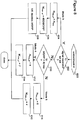
- the PCIM method 100 is illustrated in the flow diagram of Figure 8 .
- a signal received or a bit set indicates Mode 3, while the signal not received or the bit cleared indicates Mode 4 or 5 (block 602). If Mode 3 is indicated, then all frequency layers are assigned to the normal-performance group (block 604), the resource assignment is set at 480 / MGRP (block 606), and this enables the UE 50 to decide the MGRP to use (e.g., 40 ms or 80 ms) (block 608).
- the UE 50 receives a list of frequency layers to measure from the network.
- the network can send to the UE 50 a list of ten frequency layers, band 1 - band 10, but they can be sent in order of priority, say, band 7, band 3, band 4, band 8, band 2, band 1, band 10, band 9, band 5, and band 6.
- an index to that list given by N freq_g1 is sent and the index implicitly tells the UE 50 which frequency layers are in the normal-performance group, with the remaining entries belonging to the reduced-performance group.
- the UE 50 automatically knows that bands 7, 3, and 4 are in the normal-performance group while bands 8, 2, 1, 10, 9, 5, and 6 are in the reduced-performance group.
- a one-bit signal indicates to the UE 50 the group size, N freq_g1 , and the resource assignment, M inter_g1 , combination.
- a first mode Mode 6
- the normal-performance group g1
- Mode 7 or Mode 8 applies, with the group size N freg_g1 , and the resource assignment, M inter_g1 , for the normal-performance group being fixed.
- Table 6 provides the group size and resource assignment values, based on the MGRP.
- Embodiment 5 provides the following:
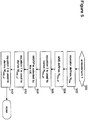
- the PCIM method 100 is illustrated in the flow diagram of Figure 9 .
- a measurement list consisting of a prioritized list of frequency layers to be measured is supplied to the UE 50 (block 702).
- An index into the measurement list, N freq _ g1 indicates which of the frequency layers is part of the normal-performance group (block 704). If a signal is received or a bit is set, the UE 50 performs the measurements in Mode 6 (block 706), in which there is no reduced-performance group (block 708), and both the MGRP (block 710) and the resource assignment (block 712) are designated by the UE 50.
- the UE 50 If instead the signal is not received or the bit is cleared (block 706), the UE 50 operates according to Table 6, above, in either Mode 7 or Mode 8. If the MGRP is not 40 ms (block 714), the UE 50 operates in Mode 7. The number of frequency layers in the normal-performance group is five (block 716) and the resource assignment is four (block 718). Otherwise, the MGRP is 40 ms (block 714) and the number of frequency layers in the normal-performance group is four (block 720) and the resource assignment is seven (block 722). By having three available modes in this embodiment, the system design of the UE 50 can be greatly simplified.
- Embodiment 6 is well-suited to situations in which the UE 50 is moving at high speeds.
- the UE 50 is able to dynamically change the high- and reduced-performance group designations. If moving at high speeds, the UE 50 can move the frequency layers and measurement requirements to the reduced-performance group. By adapting the assignment of frequency layers according to the UE speed, the measurement delay at the normal-performance group becomes manageable, in some embodiments. For example, in a situation where the UE 50 is moving at high speeds, such as on a high-speed train, the measurements are needed faster than for a UE sitting in an idle position. Thus, the size of the normal-performance group can be purposely reduced under this circumstance.
- the UE 50 can have the capability to implement any or all of the embodiments described herein. In other embodiments, the UE 50 is limited in capability to very few of the above embodiments. Practically speaking, the UE 50 is likely to adopt one of the embodiments at an initialization stage, and thereafter does not change. There can be circumstances, however, when it makes sense for the UE 50 to change its configuration, such as in Embodiment 6 when the UE 50 is moving at high speeds. In any case, if made by the UE, any change in configuration is semi-static, in some embodiments, as there is signaling overhead associated with such a change.
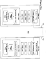
- Figures 10A and 10B are simplified block diagrams of a wireless neighborhood 800 including the eNB 20 and the UE 50, both of which are transceivers.
- the eNB 20 and the UE 50 employ the above-described PCIM method 100, according to some embodiments.
- the eNB 20 operates as a transmitter and the UE 50 operates as a receiver.
- Figure 10A shows a software-based version of the eNB 20 and the UE 50 while Figure 10B shows an ASIC-based version.
- each device includes an antenna 154, a front-end 132, a radio 136, a baseband digital signal processor (DSP) 138, and a medium access controller (MAC) 130.
- DSP baseband digital signal processor
- MAC medium access controller
- both devices have the hardware shown in each device, the eNB 20 is shown having a power amplifier 146 in its front-end 132 while the UE 50 includes a low noise amplifier 148 in its front-end.
- the eNB 20 includes a digital-to-analog converter (DAC) 134 while the UE 50 includes an analog-to-digital converter (ADC) 142.
- the UE 50 can be virtually any wireless device, such as a laptop computer, a cellular phone, or other wireless system, and can operate as a transmitter (transmit mode) or as a receiver (receive mode).
- the MAC 130 includes an embedded central processing unit (CPU) 124 and a data memory 120, such that the PCIM method 100, some portion of which is software-based, in some embodiments, can be loaded into the memory and executed by the CPU.
- CPU central processing unit
- FIG. 10A The depiction of Figure 10A is a simplified representation of the MAC 130, and other devices, circuits, and logic elements that can be part of the MAC are omitted.
- the MAC 130 interfaces with logic devices that are commonly found in transmitters and receivers: the front-end 132, the DAC 134, the ADC 142, the radio 136, and the DSP 138.
- the devices 132, 134, 136, 138, and 142 are also known herein as target modules.
- the target modules, as well as the logic devices within the MAC 130, can consist of hardware, software, or a combination of hardware and software components.
- the target modules are commonly found in most transmitters and receivers.
- the FE 132 is connected to the antenna 154, and includes a power amplifier (PA) (for the transmitter), a low noise amplifier (LNA) (for the receiver), and an antenna switch (not shown), for switching between transmitter and receiver modes.
- the DAC 134 is used to convert the digital signal coming from the DSP 138 to an analog signal prior to transmission via the radio (transmitter); conversely, the ADC 142 is used to convert the analog signal coming from the radio to a digital signal before processing by the DSP 138 (receiver).
- the radio 136 transfers the signal from base-band to the carrier frequency; at the UE 50, the radio 136 transfers the signal from carrier frequency to base-band.
- the DSP 138 demodulates the OFDM signal from the ADC 142, for processing by the MAC 130.
- the DSP 138 modulates the MAC data into an OFDM signal in base-band frequency, and sends the resulting signal to the DAC 134.
- a typical transmit operation occurs as follows: at the eNB 20, the MAC 130 sends a packet to the DSP 138.
- the DSP 138 converts the packet into a digital OFDM signal and sends it to the DAC 134.
- the DAC 134 converts the signal into an analog signal, and sends the signal to the radio 136.
- the radio 136 modulates the base-band signal to the carrier frequency and sends the signal to the power amplifier 146 of the front-end 132, which amplifies the signal to be suitable for over-air transmission via the antenna 154.
- the signal is received by the antenna 154.
- the weak analog signal is received into the low noise amplifier 148 of the front-end 132, sending the amplified analog signal to the radio 136, which filters the signal according to the selected frequency band and demodulates the carrier frequency signal into a base-band signal.
- the radio 136 sends the analog signal to the ADC 142, which converts the analog signal to a digital signal, suitable for processing by the DSP 138.
- the DSP 138 demodulates the OFDM signal and converts the signal to MAC 130 packet bytes. Other operations, such as encryption and decryption of the packets, are not shown.
- the packet received by the MAC 130 in the UE 50 is the same as the packet transmitted by the MAC 130 in the eNB 20.
- the eNB 20 and the UE 50 do not include a CPU 124 in the MAC 130.
- an application-specific integrated circuit (ASIC) 190 can drive the PCIM method 100 as a state machine implemented using logic registers (192).
- the ASIC solution of Figure 10B can be preferred over the MAC-based implementation of Figure 10A , for example, in systems in which low power consumption is important.
Landscapes
- Engineering & Computer Science (AREA)
- Signal Processing (AREA)
- Computer Networks & Wireless Communication (AREA)
- Mobile Radio Communication Systems (AREA)
- Measurement Of Resistance Or Impedance (AREA)
Applications Claiming Priority (3)
| Application Number | Priority Date | Filing Date | Title |
|---|---|---|---|
| US201461990647P | 2014-05-08 | 2014-05-08 | |
| EP15789455.1A EP3141023B1 (de) | 2014-05-08 | 2015-05-08 | Verfahren für priorisierte zellenidentifizierung und messung |
| PCT/US2015/029953 WO2015172061A1 (en) | 2014-05-08 | 2015-05-08 | Prioritized cell identification and measurement method |
Related Parent Applications (1)
| Application Number | Title | Priority Date | Filing Date |
|---|---|---|---|
| EP15789455.1A Division EP3141023B1 (de) | 2014-05-08 | 2015-05-08 | Verfahren für priorisierte zellenidentifizierung und messung |
Publications (2)
| Publication Number | Publication Date |
|---|---|
| EP3684095A1 true EP3684095A1 (de) | 2020-07-22 |
| EP3684095B1 EP3684095B1 (de) | 2024-02-28 |
Family
ID=54393058
Family Applications (2)
| Application Number | Title | Priority Date | Filing Date |
|---|---|---|---|
| EP20157780.6A Active EP3684095B1 (de) | 2014-05-08 | 2015-05-08 | Benutzerendgerät mit anwendung von leistungsanforderungen für erhöhte frequenzschichtüberwachung und rückwärtskompatibilität mit lte |
| EP15789455.1A Active EP3141023B1 (de) | 2014-05-08 | 2015-05-08 | Verfahren für priorisierte zellenidentifizierung und messung |
Family Applications After (1)
| Application Number | Title | Priority Date | Filing Date |
|---|---|---|---|
| EP15789455.1A Active EP3141023B1 (de) | 2014-05-08 | 2015-05-08 | Verfahren für priorisierte zellenidentifizierung und messung |
Country Status (9)
| Country | Link |
|---|---|
| US (2) | US9843956B2 (de) |
| EP (2) | EP3684095B1 (de) |
| JP (1) | JP6342520B2 (de) |
| KR (1) | KR101858378B1 (de) |
| AU (1) | AU2015255767B2 (de) |
| CA (1) | CA2945207C (de) |
| MX (1) | MX359224B (de) |
| RU (1) | RU2649309C1 (de) |
| WO (1) | WO2015172061A1 (de) |
Families Citing this family (3)
| Publication number | Priority date | Publication date | Assignee | Title |
|---|---|---|---|---|
| AU2015255767B2 (en) | 2014-05-08 | 2017-10-19 | Apple Inc. | Prioritized cell identification and measurement method |
| WO2022086645A1 (en) * | 2020-10-22 | 2022-04-28 | Apple Inc. | Carrier aggregation in a high speed mode of a user equipment |
| WO2023277738A1 (en) * | 2021-06-28 | 2023-01-05 | Telefonaktiebolaget Lm Ericsson (Publ) | Determining whether to perform a handover |
Citations (4)
| Publication number | Priority date | Publication date | Assignee | Title |
|---|---|---|---|---|
| WO2012122673A1 (en) * | 2011-03-15 | 2012-09-20 | Telefonaktiebolaget L.M. Ericsson (Publ) | A method and a base station for allocation measurement gaps |
| WO2015022108A1 (en) * | 2013-08-16 | 2015-02-19 | Telefonaktiebolaget L M Ericsson (Publ) | Method and apparatus for inter-frequency measurements in a communication network |
| WO2015022107A1 (en) * | 2013-08-16 | 2015-02-19 | Telefonaktiebolaget L M Ericsson (Publ) | Method and apparatus for inter-frequency measurements in a communication network |
| WO2015126568A1 (en) * | 2014-02-24 | 2015-08-27 | Intel IP Corporation | Measurement gap patterns |
Family Cites Families (29)
| Publication number | Priority date | Publication date | Assignee | Title |
|---|---|---|---|---|
| US6907228B1 (en) | 2001-08-21 | 2005-06-14 | Nortel Networks Limited | Allocating carrier frequencies for communicating beacon control signaling |
| US8270365B2 (en) * | 2005-05-04 | 2012-09-18 | Samsung Electronics Co., Ltd. | Method and apparatus for reporting inter-frequency measurement using RACH message in a mobile communication system |
| JP4716907B2 (ja) * | 2006-03-28 | 2011-07-06 | 富士通株式会社 | サブバンド通知方法及び端末装置 |
| RU2433538C2 (ru) * | 2006-10-03 | 2011-11-10 | Квэлкомм Инкорпорейтед | Синхронизация разделенных ресурсов среди множества секторов системы беспроводной связи с ofdm |
| JP4698695B2 (ja) * | 2008-03-24 | 2011-06-08 | 株式会社エヌ・ティ・ティ・ドコモ | ハンドオーバ制御方法、セル再選択方法及び移動局 |
| US8379619B2 (en) | 2009-11-06 | 2013-02-19 | Intel Corporation | Subcarrier permutation to achieve high frequency diversity of OFDMA systems |
| EP2569973B1 (de) * | 2010-05-10 | 2018-04-04 | Telefonaktiebolaget LM Ericsson (publ) | Hilfsvorrichtung und verfahren für interfrequenzmessungen |
| CN102378210A (zh) | 2010-08-17 | 2012-03-14 | 中兴通讯股份有限公司 | 多载波系统中的载波测量方法及系统 |
| US8750807B2 (en) | 2011-01-10 | 2014-06-10 | Mediatek Inc. | Measurement gap configuration in wireless communication systems with carrier aggregation |
| CN102595450B (zh) | 2011-01-10 | 2014-12-24 | 华为技术有限公司 | 测量间隙的配置方法和通信装置 |
| EP2664202B1 (de) * | 2011-01-12 | 2016-12-07 | Telefonaktiebolaget LM Ericsson (publ) | Verfahren und netzwerkknoten zur signalisierung von komplementären hilfsdaten |
| CN103167551B (zh) * | 2011-12-15 | 2016-06-29 | 华为技术有限公司 | 一种用户设备ue上报测量结果的方法和用户设备 |
| WO2013104129A1 (en) * | 2012-01-12 | 2013-07-18 | Nokia Siemens Networks Oy | Methods and devices for inter-frequency measurement by terminal apparatus |
| CN103391571B (zh) * | 2012-05-09 | 2018-12-04 | 北京三星通信技术研究有限公司 | 一种异频邻小区的测量方法及用户设备 |
| EP2739108B1 (de) * | 2012-11-28 | 2019-01-02 | Samsung Electronics Co., Ltd | Verfahren und Vorrichtung zur Kommunikationsdurchführung in einem drahtlosen Kommunikationssystem |
| WO2014185697A1 (ko) * | 2013-05-15 | 2014-11-20 | 엘지전자 주식회사 | 측정 수행 방법 및 장치 |
| CN105474682A (zh) * | 2013-08-12 | 2016-04-06 | 瑞典爱立信有限公司 | 用于异构网络中的测量的聚簇周期间隙 |
| EP3053374A1 (de) * | 2013-09-30 | 2016-08-10 | Telefonaktiebolaget LM Ericsson (publ) | Verfahren für klassenbasierte messungen auf mehreren trägern |
| US9565611B2 (en) * | 2013-11-04 | 2017-02-07 | Telefonaktiebolaget L M Ericsson (Publ) | Wireless device, network node and methods therein, computer programs and computer-readable mediums comprising the computer programs, for cell monitoring for cell reselection |
| US9660741B2 (en) * | 2014-01-29 | 2017-05-23 | Lg Electronics Inc. | Method for performing measurement |
| US9973958B2 (en) * | 2014-01-30 | 2018-05-15 | Intel IP Corporation | Systems, methods, and devices for improved inter-frequency measurement |
| RU2638567C1 (ru) * | 2014-03-04 | 2017-12-14 | ЭлДжи ЭЛЕКТРОНИКС ИНК. | Способ приема управляющей информации для приема опорного сигнала обнаружения и устройство для этого |
| WO2015149337A1 (zh) * | 2014-04-03 | 2015-10-08 | 华为技术有限公司 | 一种tdd系统中rrm测量方法及装置 |
| US20150327104A1 (en) * | 2014-05-08 | 2015-11-12 | Candy Yiu | Systems, methods, and devices for configuring measurement gaps for dual connectivity |
| AU2015255767B2 (en) | 2014-05-08 | 2017-10-19 | Apple Inc. | Prioritized cell identification and measurement method |
| EP3537759A1 (de) * | 2014-05-09 | 2019-09-11 | Sony Corporation | Vorrichtung |
| US20160081020A1 (en) * | 2014-09-16 | 2016-03-17 | Telefonaktiebolaget L M Ericsson (Publ) | Drx cycle configuration in dual connectivity |
| WO2016074883A1 (en) * | 2014-11-10 | 2016-05-19 | Telefonaktiebolaget L M Ericsson (Publ) | Methods of subframe pairing for measurement gap length configuration in dual connectivity |
| US10103867B2 (en) * | 2015-04-13 | 2018-10-16 | Alcatel Lucent | Methods, apparatuses and systems for enhancing measurement gap in synchronized networks |
-
2015
- 2015-05-08 AU AU2015255767A patent/AU2015255767B2/en active Active
- 2015-05-08 RU RU2016139444A patent/RU2649309C1/ru active
- 2015-05-08 EP EP20157780.6A patent/EP3684095B1/de active Active
- 2015-05-08 MX MX2016013085A patent/MX359224B/es active IP Right Grant
- 2015-05-08 US US15/122,495 patent/US9843956B2/en active Active
- 2015-05-08 WO PCT/US2015/029953 patent/WO2015172061A1/en active Application Filing
- 2015-05-08 EP EP15789455.1A patent/EP3141023B1/de active Active
- 2015-05-08 KR KR1020167027714A patent/KR101858378B1/ko active IP Right Grant
- 2015-05-08 JP JP2016567028A patent/JP6342520B2/ja active Active
- 2015-05-08 CA CA2945207A patent/CA2945207C/en active Active
-
2017
- 2017-11-30 US US15/827,221 patent/US11096076B2/en active Active
Patent Citations (4)
| Publication number | Priority date | Publication date | Assignee | Title |
|---|---|---|---|---|
| WO2012122673A1 (en) * | 2011-03-15 | 2012-09-20 | Telefonaktiebolaget L.M. Ericsson (Publ) | A method and a base station for allocation measurement gaps |
| WO2015022108A1 (en) * | 2013-08-16 | 2015-02-19 | Telefonaktiebolaget L M Ericsson (Publ) | Method and apparatus for inter-frequency measurements in a communication network |
| WO2015022107A1 (en) * | 2013-08-16 | 2015-02-19 | Telefonaktiebolaget L M Ericsson (Publ) | Method and apparatus for inter-frequency measurements in a communication network |
| WO2015126568A1 (en) * | 2014-02-24 | 2015-08-27 | Intel IP Corporation | Measurement gap patterns |
Non-Patent Citations (3)
| Title |
|---|
| ERICSSON: "Increasing the minimum requirements for number of carriers which can be monitored in E-UTRA connected mode", vol. RAN WG4, no. Prague, Czech Republic; 20140210 - 20140214, 9 February 2014 (2014-02-09), XP050740151, Retrieved from the Internet <URL:http://www.3gpp.org/ftp/Meetings_3GPP_SYNC/RAN/RAN4/Docs/> [retrieved on 20140209] * |
| INTEL CORPORATION: "Discussion on increasing the minimum number of carriers for UE monitoring in EUTRA", vol. RAN WG4, no. Seoul, Korea; 20140519 - 20140523, 12 May 2014 (2014-05-12), XP050823954, Retrieved from the Internet <URL:http://www.3gpp.org/ftp/tsg_ran/WG4_Radio/TSGR4_71/Docs/> [retrieved on 20140512] * |
| INTEL CORPORATION: "Further considerations on the measurement gap pattern in HeNet", vol. RAN WG4, no. Prague, Czech Republic; 20140210 - 20140214, 3 February 2014 (2014-02-03), XP050758057, Retrieved from the Internet <URL:http://www.3gpp.org/ftp/tsg_ran/WG4_Radio/TSGR4_70/Docs/> [retrieved on 20140203] * |
Also Published As
| Publication number | Publication date |
|---|---|
| CA2945207A1 (en) | 2015-11-12 |
| AU2015255767A1 (en) | 2016-10-27 |
| EP3684095B1 (de) | 2024-02-28 |
| EP3141023A4 (de) | 2017-12-20 |
| KR20160132055A (ko) | 2016-11-16 |
| US20180091996A1 (en) | 2018-03-29 |
| MX359224B (es) | 2018-09-19 |
| JP2017515423A (ja) | 2017-06-08 |
| RU2649309C1 (ru) | 2018-04-02 |
| BR112016023588A2 (pt) | 2017-08-15 |
| MX2016013085A (es) | 2017-04-27 |
| US11096076B2 (en) | 2021-08-17 |
| US20170078904A1 (en) | 2017-03-16 |
| CA2945207C (en) | 2020-12-29 |
| AU2015255767B2 (en) | 2017-10-19 |
| KR101858378B1 (ko) | 2018-05-15 |
| JP6342520B2 (ja) | 2018-06-13 |
| WO2015172061A1 (en) | 2015-11-12 |
| EP3141023B1 (de) | 2020-02-19 |
| US9843956B2 (en) | 2017-12-12 |
| EP3141023A1 (de) | 2017-03-15 |
Similar Documents
| Publication | Publication Date | Title |
|---|---|---|
| JP6028051B2 (ja) | 移動体無線装置による、非ライセンス無線周波数帯域における通信のための方法及び装置 | |
| US11133910B2 (en) | Methods and arrangements for wide bandwidth communications | |
| AU2016228025B2 (en) | Control signaling for flexible duplex in wireless communications | |
| EP3044997B1 (de) | Verfahren zur auswahl eines zugangsnetzes auf der basis von trägeraggregationsinformationen | |
| EP3183916A1 (de) | Vorrichtungen und verfahren mit übertragungsleistungsregelung und planung für in unlizenzierten bändern betriebene lte | |
| EP3432678B1 (de) | Vorrichtung und verfahren zur konfiguration eines sekundären knotens und berichterstattung in dualer konnektivität | |
| KR20110122454A (ko) | 이동통신시스템에서 복수 개의 캐리어들이 집적된 단말기의 캐리어들에 대한 효율적인 메저먼트 방법 | |
| US11096076B2 (en) | Prioritized cell identification and measurement method | |
| US20230337278A1 (en) | Method and Apparatus for Channel Occupancy Measurement | |
| EP3857931B1 (de) | Funknetzknoten, benutzergerät und in einem drahtlosen kommunikationsnetz durchgeführte verfahren | |
| US20160295582A1 (en) | Use of Blank Subframes for D2D | |
| BR112016023588B1 (pt) | Método de identificação e medição de célula priorizada |
Legal Events
| Date | Code | Title | Description |
|---|---|---|---|
| PUAI | Public reference made under article 153(3) epc to a published international application that has entered the european phase |
Free format text: ORIGINAL CODE: 0009012 |
|
| STAA | Information on the status of an ep patent application or granted ep patent |
Free format text: STATUS: REQUEST FOR EXAMINATION WAS MADE |
|
| 17P | Request for examination filed |
Effective date: 20200217 |
|
| AC | Divisional application: reference to earlier application |
Ref document number: 3141023 Country of ref document: EP Kind code of ref document: P |
|
| AK | Designated contracting states |
Kind code of ref document: A1 Designated state(s): AL AT BE BG CH CY CZ DE DK EE ES FI FR GB GR HR HU IE IS IT LI LT LU LV MC MK MT NL NO PL PT RO RS SE SI SK SM TR |
|
| STAA | Information on the status of an ep patent application or granted ep patent |
Free format text: STATUS: EXAMINATION IS IN PROGRESS |
|
| 17Q | First examination report despatched |
Effective date: 20210528 |
|
| GRAP | Despatch of communication of intention to grant a patent |
Free format text: ORIGINAL CODE: EPIDOSNIGR1 |
|
| STAA | Information on the status of an ep patent application or granted ep patent |
Free format text: STATUS: GRANT OF PATENT IS INTENDED |
|
| INTG | Intention to grant announced |
Effective date: 20231006 |
|
| GRAS | Grant fee paid |
Free format text: ORIGINAL CODE: EPIDOSNIGR3 |
|
| RAP1 | Party data changed (applicant data changed or rights of an application transferred) |
Owner name: APPLE INC. |
|
| GRAA | (expected) grant |
Free format text: ORIGINAL CODE: 0009210 |
|
| STAA | Information on the status of an ep patent application or granted ep patent |
Free format text: STATUS: THE PATENT HAS BEEN GRANTED |
|
| AC | Divisional application: reference to earlier application |
Ref document number: 3141023 Country of ref document: EP Kind code of ref document: P |
|
| AK | Designated contracting states |
Kind code of ref document: B1 Designated state(s): AL AT BE BG CH CY CZ DE DK EE ES FI FR GB GR HR HU IE IS IT LI LT LU LV MC MK MT NL NO PL PT RO RS SE SI SK SM TR |
|
| REG | Reference to a national code |
Ref country code: GB Ref legal event code: FG4D |
|
| REG | Reference to a national code |
Ref country code: CH Ref legal event code: EP |
|
| REG | Reference to a national code |
Ref country code: DE Ref legal event code: R096 Ref document number: 602015087764 Country of ref document: DE |
|
| REG | Reference to a national code |
Ref country code: IE Ref legal event code: FG4D |
|
| P01 | Opt-out of the competence of the unified patent court (upc) registered |
Effective date: 20240327 |