EP3683674A1 - Information processing device, information processing method, and information processing program - Google Patents
Information processing device, information processing method, and information processing program Download PDFInfo
- Publication number
- EP3683674A1 EP3683674A1 EP18856168.2A EP18856168A EP3683674A1 EP 3683674 A1 EP3683674 A1 EP 3683674A1 EP 18856168 A EP18856168 A EP 18856168A EP 3683674 A1 EP3683674 A1 EP 3683674A1
- Authority
- EP
- European Patent Office
- Prior art keywords
- controller data
- control
- information processing
- control programs
- editing
- Prior art date
- Legal status (The legal status is an assumption and is not a legal conclusion. Google has not performed a legal analysis and makes no representation as to the accuracy of the status listed.)
- Granted
Links
Images





Classifications
-
- G—PHYSICS
- G05—CONTROLLING; REGULATING
- G05B—CONTROL OR REGULATING SYSTEMS IN GENERAL; FUNCTIONAL ELEMENTS OF SUCH SYSTEMS; MONITORING OR TESTING ARRANGEMENTS FOR SUCH SYSTEMS OR ELEMENTS
- G05B19/00—Program-control systems
- G05B19/02—Program-control systems electric
- G05B19/04—Program control other than numerical control, i.e. in sequence controllers or logic controllers
- G05B19/05—Programmable logic controllers, e.g. simulating logic interconnections of signals according to ladder diagrams or function charts
- G05B19/056—Programming the PLC
-
- G—PHYSICS
- G06—COMPUTING OR CALCULATING; COUNTING
- G06F—ELECTRIC DIGITAL DATA PROCESSING
- G06F9/00—Arrangements for program control, e.g. control units
- G06F9/06—Arrangements for program control, e.g. control units using stored programs, i.e. using an internal store of processing equipment to receive or retain programs
- G06F9/44—Arrangements for executing specific programs
- G06F9/445—Program loading or initiating
- G06F9/44505—Configuring for program initiating, e.g. using registry, configuration files
-
- G—PHYSICS
- G05—CONTROLLING; REGULATING
- G05B—CONTROL OR REGULATING SYSTEMS IN GENERAL; FUNCTIONAL ELEMENTS OF SUCH SYSTEMS; MONITORING OR TESTING ARRANGEMENTS FOR SUCH SYSTEMS OR ELEMENTS
- G05B19/00—Program-control systems
- G05B19/02—Program-control systems electric
- G05B19/04—Program control other than numerical control, i.e. in sequence controllers or logic controllers
- G05B19/05—Programmable logic controllers, e.g. simulating logic interconnections of signals according to ladder diagrams or function charts
-
- G—PHYSICS
- G06—COMPUTING OR CALCULATING; COUNTING
- G06F—ELECTRIC DIGITAL DATA PROCESSING
- G06F8/00—Arrangements for software engineering
- G06F8/30—Creation or generation of source code
- G06F8/31—Programming languages or programming paradigms
- G06F8/313—Logic programming, e.g. PROLOG programming language
-
- G—PHYSICS
- G06—COMPUTING OR CALCULATING; COUNTING
- G06F—ELECTRIC DIGITAL DATA PROCESSING
- G06F8/00—Arrangements for software engineering
- G06F8/60—Software deployment
-
- G—PHYSICS
- G06—COMPUTING OR CALCULATING; COUNTING
- G06F—ELECTRIC DIGITAL DATA PROCESSING
- G06F8/00—Arrangements for software engineering
- G06F8/70—Software maintenance or management
- G06F8/71—Version control; Configuration management
-
- G—PHYSICS
- G06—COMPUTING OR CALCULATING; COUNTING
- G06F—ELECTRIC DIGITAL DATA PROCESSING
- G06F8/00—Arrangements for software engineering
- G06F8/30—Creation or generation of source code
- G06F8/34—Graphical or visual programming
Definitions
- the invention relates to an information processing technique that supports development of a project used for a control device.
- PLC programmable logic controller
- the PLC controls various devices connected to the PLC by executing a preset control program.
- the control program given to the PLC control is edited by an information processing device such as a PC (personal computer), as disclosed in Patent Document 1, for example.
- an information processing device is provided with a program (editing program) for creating and editing the control program.
- Patent Document 1 Japanese Laid-Open No. 2016-91066
- the invention is to facilitate the editing for a plurality of control programs.
- an information processing device includes an editing unit and a storage unit.
- the editing unit edits one or a plurality of pieces of controller data including control programs to be executed by control devices.
- the storage unit stores a sharing setting table indicating a sharing setting of the control programs respectively included in the plurality of pieces of controller data.
- the editing unit synchronizes an edited content for the control programs of the first controller data with the control programs of the second controller data.
- the edited content of the first controller data is automatically reflected to the second controller data by the sharing setting.
- the sharing setting does not mean that the control program itself is shared, but means that the contents of a plurality of control programs are always set to be the same.
- the synchronization of the control programs is a process of matching the contents of the control programs.
- the editing unit when the second controller data is created by copying the first controller data, the editing unit performs the following process. If sharing is selected for all the control programs included in the first controller data, the editing unit sets all the control programs included in the second controller data to share with all the control programs included in the first controller data, and stores the sharing setting in the sharing setting table.
- controller data with all the control programs set to be shared is easily created, and the sharing setting content is automatically stored.
- the editing unit when the second controller data is created by copying the first controller data, the editing unit performs the following process. If sharing is selected for the control program, which is already set to be shared, included in the first controller data, the editing unit sets the control program copying the control program, which is already set to be shared, included in the second controller data to share with the control program, which is already set to be shared, included in the first controller data, and stores the sharing setting in the sharing setting table.
- controller data reflecting sharing information that is already set is easily created, and the sharing setting content is automatically stored.
- the editing unit when receiving a change of the sharing setting, the editing unit reflects a changed content in the sharing setting table.
- the content of the sharing setting can be changed after copying, and the flexibility in creating controller data is improved.
- the editing unit when synchronizing the control program, synchronizes a variable used in the control program, and sets a content of the variable asynchronous.
- the synchronization of the variable is to match the variable names.
- the asynchronization of the contents of the variables is to set a state where the contents of the variables can be set as appropriate respectively.
- the information processing device includes a display unit displaying an editing screen of the controller data.
- the editing unit assigns a mark indicating the sharing setting to the control program set to be shared, and displays the mark on the display unit.
- a plurality of control programs can be edited easily.
- FIG. 1 is a functional block diagram of an information processing device according to an embodiment of the invention.
- the information processing device 10 includes an editing unit 11 and a storage unit 12.
- the editing unit 11 edits project data.
- the storage unit 12 has a project data storage area 121 and a sharing setting table 122.
- the project data includes one or a plurality of pieces of controller data.
- the controller data includes one or a plurality of control programs.
- the sharing setting table 122 stores that the control programs respectively included in the plurality of pieces of controller data are set to be shared.
- the editing unit 11 synchronizes the plurality of pieces of controller data with reference to the sharing setting table 122.
- FIG. 1 is a functional block diagram of the information processing device according to the embodiment of the invention.
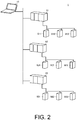
- FIG. 2 is a block diagram showing the configuration of a control system to which the information processing device according to the embodiment of the invention is connected.
- FIG. 3 is a diagram showing an example of the configuration of data created by the information processing device according to the embodiment of the invention.
- (A) of FIG. 4, (B) of FIG. 4, and (C) of FIG. 4 are diagrams showing an example of the sharing setting table according to the embodiment of the invention.
- the information processing device 10 includes the editing unit 11, the storage unit 12, an operational input unit 13, a display unit 14, and a communication control unit 15.
- the information processing device 10 is realized by, for example, a personal computer, etc.
- the control system 1 includes the information processing device 10, a plurality of control devices 91, 92, and 93, and a plurality of control target devices 911, 912, 913, 921, 922, 923, 931, 932, and 933.
- the control devices 91, 92, and 93 are realized by, for example, a so-called PLC (Programmable Logic Controller).
- the control target device 911 is a device used in a production line such as a sensor, a switch, a lamp, a motor, etc., for example. Nevertheless, the number of the control devices and the number of the control target devices are not limited to the illustration of FIG. 2 and are set as appropriate according to the control system to be realized.
- the control device 91 is connected to the control target devices 911, 912, and 913 via a control network.
- the control device 92 is connected to the control target devices 921, 922, and 923 via a control network.
- the control device 93 is connected to the control target devices 931, 932, and 933 via a control network.
- the information processing device 10 is connected to the control devices 91, 92, and 93 via a data communication network.
- the information processing device 10 creates and edits project data PD having the data configuration shown in FIG. 3 .
- the project data PD has a plurality of pieces of controller data CD1, CD2, and CD3.
- the number of pieces of controller data included in the project data PD corresponds to the number of the control devices used in the control system 1 and is one or more.
- Each of the controller data CD1, CD2, and CD3 has configuration data CFD and program data PRGD.
- the program data PRGD has a plurality of control programs PRG1, PRG2, and PRG3.
- the number of the control programs included in the program data PRGD corresponds to the number of the controls executed by the control device and is one or more. Further, the number of the control programs included in the program data PRGD may not be the same for all controller programs.
- the controller data CD1 corresponds to the control device 91
- the controller data CD2 corresponds to the control device 92
- the controller data CD3 corresponds to the control device 93.
- the configuration data CFD of the controller data CD1 is data that defines the configuration and specification (for example, the number of control target devices, EtherCAT, etc.) of the control system constituted by the control device 91 and the control target devices 911, 912, and 913.
- the configuration data CFD of the controller data CD2 is data that defines the configuration and specification (for example, the number of control target devices, EtherCAT, etc.) of the control system constituted by the control device 92 and the control target devices 921, 922, and 923.
- the configuration data CFD of the controller data CD3 is data that defines the configuration and specification (for example, the number of control target devices, EtherCAT, etc.) of the control system constituted by the control device 93 and the control target devices 931, 932, and 933.
- Each of the control programs PRG1, PRG2, and PRG3 is a program indicating the control content that the control device executes on the control target device.
- the control programs PRG1, PRG2, and PRG3 of the program data PRGD of the controller data CD1 are programs indicating the control contents that the control device 91 executes on the control target devices 911, 912, and 913.
- the control programs PRG1, PRG2, and PRG3 of the program data PRGD of the controller data CD2 are programs indicating the control contents that the control device 92 executes on the control target devices 921, 922, and 923.
- the control programs PRG1, PRG2, and PRG3 of the program data PRGD of the controller data CD3 are programs indicating the control contents that the control device 93 executes on the control target devices 931, 932, and 933.
- the information processing device 10 creates and edits a plurality of pieces of controller data CD1, CD2, and CD3 respectively corresponding to a plurality of control devices as one project data PD with one editing program.
- Each component of the information processing device 10 specifically has the following configuration.
- the editing unit 11 includes, for example, a CPU, a RAM, a ROM, etc., and is realized by a device that executes the editing program of the project data, and the editing program.
- the storage unit 12 is realized by a device including a storage medium such as a hard disk, a solid state drive, etc.
- the operational input unit 13 includes, for example, a keyboard, a mouse, a touch panel, etc.
- the operational input unit 13 receives an operation input from a user such as a programmer, and gives the operation input to the editing unit 11.
- the editing unit 11 creates and edits the project data PD according to the operation content.
- the display unit 14 includes, for example, a liquid crystal display, etc.
- the display unit 14 displays the editing screen generated by the editing unit 11.
- the communication control unit 15 includes, for example, a so-called network adapter, etc.
- the communication control unit 15 is connected to the data communication network shown in FIG. 2 and outputs the controller data CD1, CD2, and CD3 of the project data PD from the editing unit 11 to the control devices 91, 92, and 93.
- the storage unit 12 has the project data storage area 121 and the sharing setting table 122.
- the project data storage area 121 stores the project data PD including the plurality of pieces of controller data CD1, CD2, and CD3.
- the sharing setting table 122 stores a shared state of the control programs PRG included in each of the controller data CD1, CD2, and CD3.
- the shared state does not mean that the control program itself is shared and held between the plurality of pieces of controller data, but means a state where the content of the target control program is always the same between the plurality of pieces of controller data.
- the mark ⁇ in (A) of FIG. 4, (B) of FIG. 4, and (C) of FIG. 4 and the mark A in (B) of FIG. 4 indicate the shared state, and such a relationship is stored in the sharing setting table 122 as data.
- the editing unit 11 refers to the sharing setting table 122 to create and edit the plurality of pieces of controller data CD1, CD2, and CD3 constituting the project data PD.
- the editing unit 11 refers to the sharing setting table 122 and synchronizes the control program in the shared state with the changed control program.
- the process of synchronizing the control programs is a process of matching the content of the control program in the shared state with the content of the control program changed by the editing operation.
- the process of matching the contents corresponds to the "synchronizing" process of the invention.
- the information processing device 10 automatically changes the content of the control program of other controller data which needs to have the same content. Therefore, it is necessary to include control programs having the same contents in the plurality of controller programs, and when these control programs are changed, the programmer can easily edit the control programs of a plurality of pieces of controller data.
- FIG. 5 is a flowchart showing an example of the process of creating the project data.
- the editing unit 11 receives an instruction to create project data and an instruction to create controller data from the operational input unit 13, and creates the controller data (S11). Then, the editing unit 11 creates configuration data and program data as the controller data (S12).
- FIG. 6 is a diagram showing an example of the editing screen.
- (B) of FIG. 6 is an enlarged diagram showing an example of a multi-view explorer window in the editing screen.
- the editing screen 140 as shown in (A) of FIG. 6 is formed by the editing unit 11, and the editing screen 140 is displayed on the display unit 14.
- the editing screen 140 has a program editing window 141, a multi-view explorer window 142, and a tool window 143.
- the program editing window 141 is arranged at the center of the editing screen 140, and the multi-view explorer window 142 and the tool window 143 are arranged on both sides of the program editing window 141.
- variant contents such as a control program, configuration data, etc. are displayed.
- the multi-view explorer window 142 the configuration, hierarchy, etc. of the data and program to be edited are displayed.
- various tools for editing are displayed in the tool window 143.
- a controller name window 421 and a configuration tree 422 are displayed in the multi-view explorer window 142.
- the controller name window 421 displays the name of the currently edited controller program and the name of the editable controller program.
- only the name of the currently edited controller program is displayed.
- the configuration data, the configuration of the program data, and the tree structure included in the controller program displayed in the controller name window 421 are displayed in the configuration tree.
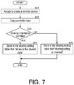
- FIG. 7 is a flowchart showing an example of a process of copying controller data (creating a derived device).
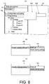
- A) of FIG. 8 is an enlarged diagram of the editing screen showing a state of instructing the process of copying controller data (creating a derived device)
- B) of FIG. 8 is a diagram showing a state of selecting a tab for sharing all
- C) of FIG. 8 is a diagram showing a state of selecting a tab for inheriting sharing setting.
- the editing unit 11 receives an instruction to copy controller data, that is, an instruction to create a derived device from the operational input unit 13 (S21). For example, as shown in (A) of FIG. 8 , if a tab 424 for creating a derived device is selected by a predetermined operation input (for example, right-clicking and selecting with a mouse) when the controller data Controller1 is in the editing state, the editing unit 11 receives an instruction to copy controller data, that is, an instruction to create a derived device. Further, as shown in (B) of FIG. 8 and (C) of FIG. 8 , when the type of sharing is selected by a newly displayed tab 425 for selecting sharing, the editing unit 11 also accepts this content.
- a predetermined operation input for example, right-clicking and selecting with a mouse
- the editing unit 11 accepts that all the control programs included in the controller data to be edited are the targets to be shared.
- the editing unit 11 accepts that only the control program, which is already in the shared state, included in the controller data to be edited is the target to be shared.
- the editing unit 11 copies the controller data to be edited and creates new controller data according to the instruction to copy controller data, that is, the instruction to create a derived device (S22).
- the editing unit 11 assigns a name different from the controller data to be edited to the newly created controller data.
- the controller data to be edited is Controller1
- the copied controller data is assigned Controller2.
- the editing unit 11 stores the copied controller data in the project data storage area 121 of the storage unit 12.
- the editing unit 11 determines a sharing inheritance condition according to the selected content of the tab 425 for selecting sharing (S23).
- the editing unit 11 stores in the sharing setting table 122 that all the control programs of the controller data to be edited (the controller data of the copy source) and all the control programs of the controller data created by copying are in the shared state (S24). For example, it corresponds to the cases of copying from the controller data Controller1 to the controller data Controller2, copying from the controller data Controller1 to the controller data Controller3, and copying from the controller data Controller2 to the controller data Controller3 shown in (A) of FIG. 4 , and copying from the controller data Controller2 to the controller data Controller3 shown in (B) of FIG. 4 . Then, corresponding to these cases, the editing unit 11 stores in the sharing setting table 122 information indicating that they are in a shared relationship as indicated by the mark ⁇ in (A) of FIG. 4 and the mark ⁇ in (B) of FIG. 4 .
- the editing unit 11 stores in the sharing setting table 122 that the control program that has already been set in the shared state in the controller data to be edited (the controller data of the copy source) and the control program that copies the control program in the controller data created by copying (the control program that is already in the shared state in the copy source) are in the shared state (S25). For example, it corresponds to the cases of copying from the controller data Controller2 to the controller data Controller3 shown in (B) of FIG. 4 , and copying from the controller data Controller1 to the controller data Controller3 and copying from the controller data Controller2 to the controller data Controller3 shown in (C) of FIG. 4 . Then, corresponding to these cases, the editing unit 11 stores in the sharing setting table 122 information indicating that they are in a shared relationship as indicated by the mark ⁇ in (B) of FIG. 4 and (C) of FIG. 4 .
- the information processing device 10 can maintain the shared state of the control programs of a plurality of pieces of controller data. Further, the setting of the shared state is automatically stored and the programmer does not need to individually input the setting of sharing.
- each variable for example, global variable
- the content of the variable for example, value
- the shared state is also displayed in the multi-view explorer window 142.
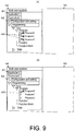
- FIG. 9 and (B) of FIG. 9 are enlarged diagrams of the multi-view explorer window when a control program in the shared state is present.
- A) of FIG. 9 shows a case where a plurality of control programs Program0, Program 1, and Program2 in the controller data Controller1 are in the shared state
- (B) of FIG. 9 shows a case where a plurality of control programs Program0 in the controller data Controller1 are in the shared state.
- the editing unit 11 displays sharing marks 420 at the positions of the control programs Program0, Program 1, and Program2 in the configuration tree 422.
- the editing unit 11 displays the sharing mark 420 at the position of the control program Program0 in the configuration tree 422.
- FIG. 10 is a flowchart showing an example of a process of synchronizing control programs between controller data.
- the editing unit 11 receives an instruction to edit the control program of the controller data from the operational input unit 13, and edits the control program of the controller data (S31).
- the editing unit 11 refers to the sharing setting table 122 to detect whether the control program being edited is in the shared state (S32). If the control program being edited is in the shared state (S33: YES), the editing unit 11 synchronizes the control program of other controller data in the shared state with the control program being edited based on the sharing setting table 122 (S34).
- the synchronizing process is to match the content of the control program of other controller data in the shared state with the content of the control program being edited.
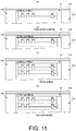
- FIG. 11, (B) of FIG. 11, (C) of FIG. 11, and (D) of FIG. 11 are diagrams showing change of the content of a control program when synchronization is performed.
- (A) of FIG. 11 shows a state before editing the control program of the controller data Controller1, and (B) of FIG. 11 shows a state where the controller data Controller2 has been created by copying.
- (C) of FIG. 11 shows a state after editing the control program of the controller data Controller1, and (D) of FIG. 11 shows a state where the controller data Controller2 after synchronization has been created.
- the editing unit 11 copies the controller data Controller1 to create the controller data Controller2, and thereby, as shown in (A) of FIG. 11 and (B) of FIG. 11 , the same control programs are configured in the controller data Controller1 and the controller data Controller2. At this time, if sharing is set, the content thereof is stored in the sharing setting table 122.
- the editing unit 11 edits the control program of the controller data Controller1 in this state. For example, as shown in (C) of FIG. 11 , the content of the control program of the controller data Controller1 is added.
- the editing unit 11 detects that the control program of the controller data Controller1 is in the shared state, and synchronizes the control program of the controller data Controller2 in the shared state with the control program of the controller data Controller1. That is, the editing unit 11 automatically changes the content of the control program of Controller2 to the content of the control program of the controller data Controller1.
- the control program of the controller data Controller2 automatically matches the control program of the controller data Controller1 shown in (C) of FIG. 11 .
- the editing unit 11 displays a sharing setting window 427 as shown in (B) of FIG. 12 .
- the program, which is the sharing target, in the controller data being edited is displayed as a "sharing target".
- a table 428 for setting the sharing destination is displayed in the sharing setting window 427.
- the table 428 has a controller name (name of the controller program) and a check box for selecting whether to enter the shared state.
- the editing unit 11 sets the control program of the controller data which is the sharing target and the control program of the controller data of the sharing destination to the shared state. For example, in the case of (B) of FIG. 12 , the editing unit 11 sets the control program Program2 of the controller data Controller1 and the control program Program2 of the controller data Controller2 to the shared state.
- the editing unit 11 sets the control program of the controller data which is the sharing target and the control program of the controller data of the sharing destination to cancel the shared state. For example, in the case corresponding to (B) of FIG. 12 , the editing unit 11 sets the control program Program2 of the controller data Controller1 and the control program Program2 of the controller data Controller2 to cancel the shared state.
- the sharing setting can be changed as appropriate.
- the programmer can edit a plurality of pieces of controller data freely.
- the above illustrates an embodiment of setting the controller data for each control device.
- the invention can also be used for editing controller data when one of a plurality of pieces of controller data is selectively set according to the situations for one control device.
Landscapes
- Engineering & Computer Science (AREA)
- Software Systems (AREA)
- Theoretical Computer Science (AREA)
- General Engineering & Computer Science (AREA)
- Physics & Mathematics (AREA)
- General Physics & Mathematics (AREA)
- Computing Systems (AREA)
- Automation & Control Theory (AREA)
- Computer Security & Cryptography (AREA)
- Programmable Controllers (AREA)
- Stored Programmes (AREA)
Abstract
Description
- The invention relates to an information processing technique that supports development of a project used for a control device.
- Currently, a programmable logic controller (hereinafter, referred to as PLC) is widely used as an industrial control device.
- The PLC controls various devices connected to the PLC by executing a preset control program.
- The control program given to the PLC control is edited by an information processing device such as a PC (personal computer), as disclosed in
Patent Document 1, for example. Such an information processing device is provided with a program (editing program) for creating and editing the control program. - [Patent Document 1] Japanese Laid-Open No.
2016-91066 - For the information processing device provided with the conventional editing program as disclosed in
Patent Document 1, it is necessary to create a new control program for each controller. Further, although it is possible to simply copy one control program in the conventional information processing device, each of a plurality of control programs has to be edited individually. Therefore, even if the same editing is performed on a plurality of control programs, the same editing has to be performed individually for each control program. - As described above, with the conventional information processing device, it may take time and effort to edit a plurality of control programs.
- Therefore, the invention is to facilitate the editing for a plurality of control programs.
- In an example of the disclosure, an information processing device includes an editing unit and a storage unit. The editing unit edits one or a plurality of pieces of controller data including control programs to be executed by control devices. The storage unit stores a sharing setting table indicating a sharing setting of the control programs respectively included in the plurality of pieces of controller data. When control programs of first controller data and control programs of second controller data included in the plurality of controllers are set to be shared, the editing unit synchronizes an edited content for the control programs of the first controller data with the control programs of the second controller data.
- In this configuration, the edited content of the first controller data is automatically reflected to the second controller data by the sharing setting. The sharing setting does not mean that the control program itself is shared, but means that the contents of a plurality of control programs are always set to be the same. In addition, the synchronization of the control programs is a process of matching the contents of the control programs.
- In an example of the disclosure, when the second controller data is created by copying the first controller data, the editing unit performs the following process. If sharing is selected for all the control programs included in the first controller data, the editing unit sets all the control programs included in the second controller data to share with all the control programs included in the first controller data, and stores the sharing setting in the sharing setting table.
- In this configuration, controller data with all the control programs set to be shared is easily created, and the sharing setting content is automatically stored.
- In an example of the disclosure, when the second controller data is created by copying the first controller data, the editing unit performs the following process. If sharing is selected for the control program, which is already set to be shared, included in the first controller data, the editing unit sets the control program copying the control program, which is already set to be shared, included in the second controller data to share with the control program, which is already set to be shared, included in the first controller data, and stores the sharing setting in the sharing setting table.
- In this configuration, controller data reflecting sharing information that is already set is easily created, and the sharing setting content is automatically stored.
- In an example of the disclosure, when receiving a change of the sharing setting, the editing unit reflects a changed content in the sharing setting table.
- In this configuration, the content of the sharing setting can be changed after copying, and the flexibility in creating controller data is improved.
- In an example of the disclosure, when synchronizing the control program, the editing unit synchronizes a variable used in the control program, and sets a content of the variable asynchronous. The synchronization of the variable is to match the variable names. The asynchronization of the contents of the variables is to set a state where the contents of the variables can be set as appropriate respectively.
- In this configuration, when the settings are different for the devices to be controlled, the same setting is not made to the control devices to prevent an unintentional malfunction.
- In an example of the disclosure, the information processing device includes a display unit displaying an editing screen of the controller data. The editing unit assigns a mark indicating the sharing setting to the control program set to be shared, and displays the mark on the display unit.
- In this configuration, the state of the sharing setting for each control program is visually recognized by the programmer easily.
- According to the invention, a plurality of control programs can be edited easily.
-
-
FIG. 1 is a functional block diagram of an information processing device according to an embodiment of the invention. -
FIG. 2 is a block diagram showing the configuration of a control system to which the information processing device according to the embodiment of the invention is connected. -
FIG. 3 is a diagram showing an example of the configuration of data created by the information processing device according to the embodiment of the invention.
(A) ofFIG. 4, (B) ofFIG. 4, and (C) ofFIG. 4 are diagrams showing an example of a sharing setting table according to the embodiment of the invention. -
FIG. 5 is a flowchart showing an example of a process of creating project data.
(A) ofFIG. 6 is a diagram showing an example of an editing screen, and (B) ofFIG. 6 is an enlarged diagram showing an example of a multi-view explorer window in the editing screen. -
FIG. 7 is a flowchart showing an example of a process of copying controller data (creating a derived device).
(A) ofFIG. 8 is an enlarged diagram of the editing screen showing a state of instructing the process of copying controller data (creating a derived device), (B) ofFIG. 8 is a diagram showing a state of selecting a tab for sharing all, and (C) ofFIG. 8 is a diagram showing a state of selecting a tab for inheriting the sharing setting. (A) ofFIG. 9 and (B) ofFIG. 9 are enlarged diagrams of the multi-view explorer window when a control program in a shared state is present. -
FIG. 10 is a flowchart showing an example of a process of synchronizing control programs between controller data.
(A) ofFIG. 11, (B) ofFIG. 11, (C) ofFIG. 11, and (D) ofFIG. 11 are diagrams showing change of the content of a control program when synchronization is performed.
(A) ofFIG. 12 is an enlarged diagram showing the multi-view explorer window when the sharing setting is changed, and (B) ofFIG. 12 is an enlarged diagram of a sharing setting window. - Hereinafter, embodiments of the invention will be described with reference to the drawings.
- First, an example of application of the invention will be described with reference to
FIG. 1. FIG. 1 is a functional block diagram of an information processing device according to an embodiment of the invention. - As shown in
FIG. 1 , theinformation processing device 10 includes anediting unit 11 and astorage unit 12. Theediting unit 11 edits project data. Thestorage unit 12 has a projectdata storage area 121 and a sharing setting table 122. - The project data includes one or a plurality of pieces of controller data. The controller data includes one or a plurality of control programs. The sharing setting table 122 stores that the control programs respectively included in the plurality of pieces of controller data are set to be shared.
- The
editing unit 11 synchronizes the plurality of pieces of controller data with reference to the sharing setting table 122. - Next, the configuration of the information processing device according to the embodiment of the invention will be described with reference to the drawings. As described above,
FIG. 1 is a functional block diagram of the information processing device according to the embodiment of the invention.FIG. 2 is a block diagram showing the configuration of a control system to which the information processing device according to the embodiment of the invention is connected.FIG. 3 is a diagram showing an example of the configuration of data created by the information processing device according to the embodiment of the invention. (A) ofFIG. 4, (B) ofFIG. 4, and (C) ofFIG. 4 are diagrams showing an example of the sharing setting table according to the embodiment of the invention. - As shown in
FIG. 1 , theinformation processing device 10 includes theediting unit 11, thestorage unit 12, anoperational input unit 13, adisplay unit 14, and acommunication control unit 15. Theinformation processing device 10 is realized by, for example, a personal computer, etc. - In addition, as shown in
FIG. 2 , theinformation processing device 10 is included in thecontrol system 1. Thecontrol system 1 includes theinformation processing device 10, a plurality ofcontrol devices control target devices control devices control target device 911 is a device used in a production line such as a sensor, a switch, a lamp, a motor, etc., for example. Nevertheless, the number of the control devices and the number of the control target devices are not limited to the illustration ofFIG. 2 and are set as appropriate according to the control system to be realized. - The control device 91 is connected to the
control target devices control device 92 is connected to thecontrol target devices control device 93 is connected to thecontrol target devices information processing device 10 is connected to thecontrol devices - The
information processing device 10 creates and edits project data PD having the data configuration shown inFIG. 3 . - As shown in
FIG. 3 , the project data PD has a plurality of pieces of controller data CD1, CD2, and CD3. The number of pieces of controller data included in the project data PD corresponds to the number of the control devices used in thecontrol system 1 and is one or more. - Each of the controller data CD1, CD2, and CD3 has configuration data CFD and program data PRGD. The program data PRGD has a plurality of control programs PRG1, PRG2, and PRG3. The number of the control programs included in the program data PRGD corresponds to the number of the controls executed by the control device and is one or more. Further, the number of the control programs included in the program data PRGD may not be the same for all controller programs.
- Here, for example, the controller data CD1 corresponds to the control device 91, the controller data CD2 corresponds to the
control device 92, and the controller data CD3 corresponds to thecontrol device 93. The configuration data CFD of the controller data CD1 is data that defines the configuration and specification (for example, the number of control target devices, EtherCAT, etc.) of the control system constituted by the control device 91 and thecontrol target devices control device 92 and thecontrol target devices control device 93 and thecontrol target devices - Each of the control programs PRG1, PRG2, and PRG3 is a program indicating the control content that the control device executes on the control target device. For example, the control programs PRG1, PRG2, and PRG3 of the program data PRGD of the controller data CD1 are programs indicating the control contents that the control device 91 executes on the
control target devices control device 92 executes on thecontrol target devices control device 93 executes on thecontrol target devices - As described above, the
information processing device 10 creates and edits a plurality of pieces of controller data CD1, CD2, and CD3 respectively corresponding to a plurality of control devices as one project data PD with one editing program. - Each component of the
information processing device 10 specifically has the following configuration. - The
editing unit 11 includes, for example, a CPU, a RAM, a ROM, etc., and is realized by a device that executes the editing program of the project data, and the editing program. Thestorage unit 12 is realized by a device including a storage medium such as a hard disk, a solid state drive, etc. - The
operational input unit 13 includes, for example, a keyboard, a mouse, a touch panel, etc. Theoperational input unit 13 receives an operation input from a user such as a programmer, and gives the operation input to theediting unit 11. Theediting unit 11 creates and edits the project data PD according to the operation content. - The
display unit 14 includes, for example, a liquid crystal display, etc. Thedisplay unit 14 displays the editing screen generated by theediting unit 11. - The
communication control unit 15 includes, for example, a so-called network adapter, etc. Thecommunication control unit 15 is connected to the data communication network shown inFIG. 2 and outputs the controller data CD1, CD2, and CD3 of the project data PD from theediting unit 11 to thecontrol devices - The
storage unit 12 has the projectdata storage area 121 and the sharing setting table 122. The projectdata storage area 121 stores the project data PD including the plurality of pieces of controller data CD1, CD2, and CD3. - The sharing setting table 122 stores a shared state of the control programs PRG included in each of the controller data CD1, CD2, and CD3. The shared state does not mean that the control program itself is shared and held between the plurality of pieces of controller data, but means a state where the content of the target control program is always the same between the plurality of pieces of controller data. For example, the mark ○ in (A) of
FIG. 4, (B) ofFIG. 4, and (C) ofFIG. 4 and the mark A in (B) ofFIG. 4 indicate the shared state, and such a relationship is stored in the sharing setting table 122 as data. - In such a configuration, the
editing unit 11 refers to the sharing setting table 122 to create and edit the plurality of pieces of controller data CD1, CD2, and CD3 constituting the project data PD. For example, when the content of the control program is changed, theediting unit 11 refers to the sharing setting table 122 and synchronizes the control program in the shared state with the changed control program. Here, the process of synchronizing the control programs is a process of matching the content of the control program in the shared state with the content of the control program changed by the editing operation. The process of matching the contents corresponds to the "synchronizing" process of the invention. - In the case of (A) of
FIG. 4 , when the control program Program0 of the controller data Controller1 (CD1) is changed, the control program Program0 of the controller data Controller2 (CD2) and the control program Program0 of the controller data Controller3 (CD3) are also changed to the same content. - However, in the cases of (B) of
FIG. 4 and (C) ofFIG. 4 , even if the control program Program2 of the controller data Controller1 (CD1) is changed, the control program Program2 of the controller data Controller2 (CD2) and the control program Program2 of the controller data Controller3 (CD3) are not changed. - Further, in the case of (B) of
FIG. 4 , when the control program Program2 of the controller data Controller2 (CD2) is changed, the control program Program2 of the controller data Controller3 (CD3) is changed to the same content, but the control program Program2 of the controller data Controller1 (CD1) is not changed. - Thus, if the control program of one controller data is changed, the
information processing device 10 automatically changes the content of the control program of other controller data which needs to have the same content. Therefore, it is necessary to include control programs having the same contents in the plurality of controller programs, and when these control programs are changed, the programmer can easily edit the control programs of a plurality of pieces of controller data. - A specific editing process executed by the
editing unit 11 will be described with reference to the drawings. -
FIG. 5 is a flowchart showing an example of the process of creating the project data. - As shown in
FIG. 5 , theediting unit 11 receives an instruction to create project data and an instruction to create controller data from theoperational input unit 13, and creates the controller data (S11). Then, theediting unit 11 creates configuration data and program data as the controller data (S12). - (A) of
FIG. 6 is a diagram showing an example of the editing screen. (B) ofFIG. 6 is an enlarged diagram showing an example of a multi-view explorer window in the editing screen. - When the editing program is executed, the
editing screen 140 as shown in (A) ofFIG. 6 is formed by theediting unit 11, and theediting screen 140 is displayed on thedisplay unit 14. Theediting screen 140 has aprogram editing window 141, amulti-view explorer window 142, and atool window 143. Theprogram editing window 141 is arranged at the center of theediting screen 140, and themulti-view explorer window 142 and thetool window 143 are arranged on both sides of theprogram editing window 141. In theprogram editing window 141, variant contents such as a control program, configuration data, etc. are displayed. In themulti-view explorer window 142, the configuration, hierarchy, etc. of the data and program to be edited are displayed. Although not shown, various tools for editing are displayed in thetool window 143. - As shown in (B) of
FIG. 6 , acontroller name window 421 and aconfiguration tree 422 are displayed in themulti-view explorer window 142. Thecontroller name window 421 displays the name of the currently edited controller program and the name of the editable controller program. In (B) ofFIG. 6 , only the name of the currently edited controller program is displayed. The configuration data, the configuration of the program data, and the tree structure included in the controller program displayed in thecontroller name window 421 are displayed in the configuration tree. -
FIG. 7 is a flowchart showing an example of a process of copying controller data (creating a derived device). (A) ofFIG. 8 is an enlarged diagram of the editing screen showing a state of instructing the process of copying controller data (creating a derived device), (B) ofFIG. 8 is a diagram showing a state of selecting a tab for sharing all, and (C) ofFIG. 8 is a diagram showing a state of selecting a tab for inheriting sharing setting. - As shown in
FIG. 7 , theediting unit 11 receives an instruction to copy controller data, that is, an instruction to create a derived device from the operational input unit 13 (S21). For example, as shown in (A) ofFIG. 8 , if atab 424 for creating a derived device is selected by a predetermined operation input (for example, right-clicking and selecting with a mouse) when the controller data Controller1 is in the editing state, theediting unit 11 receives an instruction to copy controller data, that is, an instruction to create a derived device. Further, as shown in (B) ofFIG. 8 and (C) ofFIG. 8 , when the type of sharing is selected by a newly displayedtab 425 for selecting sharing, theediting unit 11 also accepts this content. For example, by selecting thetab 425 of "share all" as shown in (B) ofFIG. 8 , theediting unit 11 accepts that all the control programs included in the controller data to be edited are the targets to be shared. On the other hand, by selecting thetab 425 of "inherit sharing setting" as shown in (C) ofFIG. 8 , theediting unit 11 accepts that only the control program, which is already in the shared state, included in the controller data to be edited is the target to be shared. - The
editing unit 11 copies the controller data to be edited and creates new controller data according to the instruction to copy controller data, that is, the instruction to create a derived device (S22). Theediting unit 11 assigns a name different from the controller data to be edited to the newly created controller data. Here, for example, the controller data to be edited is Controller1, whereas the copied controller data is assigned Controller2. Theediting unit 11 stores the copied controller data in the projectdata storage area 121 of thestorage unit 12. - The
editing unit 11 determines a sharing inheritance condition according to the selected content of thetab 425 for selecting sharing (S23). - If the sharing inheritance condition is "share all" (S23: ALL), the
editing unit 11 stores in the sharing setting table 122 that all the control programs of the controller data to be edited (the controller data of the copy source) and all the control programs of the controller data created by copying are in the shared state (S24). For example, it corresponds to the cases of copying from the controller data Controller1 to the controller data Controller2, copying from the controller data Controller1 to the controller data Controller3, and copying from the controller data Controller2 to the controller data Controller3 shown in (A) ofFIG. 4 , and copying from the controller data Controller2 to the controller data Controller3 shown in (B) ofFIG. 4 . Then, corresponding to these cases, theediting unit 11 stores in the sharing setting table 122 information indicating that they are in a shared relationship as indicated by the mark ○ in (A) ofFIG. 4 and the mark ▲ in (B) ofFIG. 4 . - If the sharing inheritance condition is "inherit sharing setting" (S23: SEL), the
editing unit 11 stores in the sharing setting table 122 that the control program that has already been set in the shared state in the controller data to be edited (the controller data of the copy source) and the control program that copies the control program in the controller data created by copying (the control program that is already in the shared state in the copy source) are in the shared state (S25). For example, it corresponds to the cases of copying from the controller data Controller2 to the controller data Controller3 shown in (B) ofFIG. 4 , and copying from the controller data Controller1 to the controller data Controller3 and copying from the controller data Controller2 to the controller data Controller3 shown in (C) ofFIG. 4 . Then, corresponding to these cases, theediting unit 11 stores in the sharing setting table 122 information indicating that they are in a shared relationship as indicated by the mark ○ in (B) ofFIG. 4 and (C) ofFIG. 4 . - Thereby, the
information processing device 10 can maintain the shared state of the control programs of a plurality of pieces of controller data. Further, the setting of the shared state is automatically stored and the programmer does not need to individually input the setting of sharing. - At this time, in the copied control program, each variable (for example, global variable) is copied to be the same as that of the control program of the copy source (synchronized), but the content of the variable (for example, value) is not copied (asynchronous). Thereby, in the case where the control target device is similar but the content of the variable has to be changed, it is possible to prevent the content of the same variable from being set unintentionally. As a result, a malfunction of the control target device is prevented.
- The shared state is also displayed in the
multi-view explorer window 142. (A) ofFIG. 9 and (B) ofFIG. 9 are enlarged diagrams of the multi-view explorer window when a control program in the shared state is present. (A) ofFIG. 9 shows a case where a plurality of control programs Program0,Program 1, and Program2 in the controller data Controller1 are in the shared state, and (B) ofFIG. 9 shows a case where a plurality of control programs Program0 in the controller data Controller1 are in the shared state. - As shown in (A) of
FIG. 9 , when the control programs Program0, Program1, and Program2 are in the shared state, theediting unit 11displays sharing marks 420 at the positions of the control programs Program0,Program 1, and Program2 in theconfiguration tree 422. As shown in (B) ofFIG. 9 , when the control program Program0 is in the shared state, theediting unit 11 displays thesharing mark 420 at the position of the control program Program0 in theconfiguration tree 422. - By displaying such a
sharing mark 420, the programmer can easily recognize the control program in the shared state with certainty. -
FIG. 10 is a flowchart showing an example of a process of synchronizing control programs between controller data. - The
editing unit 11 receives an instruction to edit the control program of the controller data from theoperational input unit 13, and edits the control program of the controller data (S31). Theediting unit 11 refers to the sharing setting table 122 to detect whether the control program being edited is in the shared state (S32). If the control program being edited is in the shared state (S33: YES), theediting unit 11 synchronizes the control program of other controller data in the shared state with the control program being edited based on the sharing setting table 122 (S34). Here, the synchronizing process is to match the content of the control program of other controller data in the shared state with the content of the control program being edited. - On the other hand, if the control program being edited is not in the shared state (S33: NO), the
editing unit 11 does not perform synchronization. - (A) of
FIG. 11, (B) ofFIG. 11, (C) ofFIG. 11, and (D) ofFIG. 11 are diagrams showing change of the content of a control program when synchronization is performed. (A) ofFIG. 11 shows a state before editing the control program of the controller data Controller1, and (B) ofFIG. 11 shows a state where the controller data Controller2 has been created by copying. (C) ofFIG. 11 shows a state after editing the control program of the controller data Controller1, and (D) ofFIG. 11 shows a state where the controller data Controller2 after synchronization has been created. - The
editing unit 11 copies the controller data Controller1 to create the controller data Controller2, and thereby, as shown in (A) ofFIG. 11 and (B) ofFIG. 11 , the same control programs are configured in the controller data Controller1 and the controller data Controller2. At this time, if sharing is set, the content thereof is stored in the sharing setting table 122. - The
editing unit 11 edits the control program of the controller data Controller1 in this state. For example, as shown in (C) ofFIG. 11 , the content of the control program of the controller data Controller1 is added. - The
editing unit 11 detects that the control program of the controller data Controller1 is in the shared state, and synchronizes the control program of the controller data Controller2 in the shared state with the control program of the controller data Controller1. That is, theediting unit 11 automatically changes the content of the control program of Controller2 to the content of the control program of the controller data Controller1. Thus, as shown in (D) ofFIG. 11 , the control program of the controller data Controller2 automatically matches the control program of the controller data Controller1 shown in (C) ofFIG. 11 . - When the same control program is used in a plurality of pieces of controller data, by executing such processing, if the control program of one controller data is edited, the control program of other controller data in the shared state is updated automatically. Therefore, the programmer can easily edit a plurality of pieces of controller data.
- (D) Change of sharing setting
(A) ofFIG. 12 is an enlarged diagram showing the multi-view explorer window when the sharing setting is changed. (B) ofFIG. 12 is an enlarged diagram of the sharing setting window. - As shown in (A) of
FIG. 12 , if atab 426 for changing the sharing setting is selected by a predetermined operation input (for example, right-clicking and selecting with a mouse) when the controller data Controller1 is in the editing state, theediting unit 11 displays asharing setting window 427 as shown in (B) ofFIG. 12 . - In the
sharing setting window 427, the program, which is the sharing target, in the controller data being edited is displayed as a "sharing target". In addition, a table 428 for setting the sharing destination is displayed in thesharing setting window 427. The table 428 has a controller name (name of the controller program) and a check box for selecting whether to enter the shared state. - When an instruction to check the check box is received, the
editing unit 11 sets the control program of the controller data which is the sharing target and the control program of the controller data of the sharing destination to the shared state. For example, in the case of (B) ofFIG. 12 , theediting unit 11 sets the control program Program2 of the controller data Controller1 and the control program Program2 of the controller data Controller2 to the shared state. - Further, when an instruction to cancel the check in the check box is received, the
editing unit 11 sets the control program of the controller data which is the sharing target and the control program of the controller data of the sharing destination to cancel the shared state. For example, in the case corresponding to (B) ofFIG. 12 , theediting unit 11 sets the control program Program2 of the controller data Controller1 and the control program Program2 of the controller data Controller2 to cancel the shared state. - By using such a configuration and processing, the sharing setting can be changed as appropriate. Thereby, the programmer can edit a plurality of pieces of controller data freely.
- The above illustrates an embodiment of setting the controller data for each control device. However, the invention can also be used for editing controller data when one of a plurality of pieces of controller data is selectively set according to the situations for one control device.
- The embodiments of the invention described above are merely examples of the invention in every respect. It goes without saying that various modifications can be made without departing from the scope of the invention.
-
- 1: Control system
- 10: Information processing device
- 11: Editing unit
- 12: Storage unit
- 13: Operational input unit
- 14: Display unit
- 15: Communication control unit
- 91, 92, 93: Control device
- 121: Project data storage area
- 122: Sharing setting table
- 140: Editing screen
- 141: Program editing window
- 142: Multi-view explorer window
- 143: Tool window
- 420: Sharing mark
- 421: Controller name window
- 422: Configuration tree
- 424, 425, 426: Tab
- 427: Sharing setting window
- 428: Table
- 911, 921, 931: Control target device
- CD1, CD2, CD3: Controller data
- CFD: Configuration data
- PD: Project data
- PRG1, PRG2, PRG3: Control program
- PRGD: Program data
Claims (8)
- An information processing device, comprising:an editing unit editing one or a plurality of pieces of controller data including control programs to be executed by control devices; anda storage unit storing a sharing setting table indicating a sharing setting of the control programs respectively included in the plurality of pieces of controller data,wherein when control programs of first controller data and control programs of second controller data included in the plurality of controllers are set to be shared, the editing unit synchronizes an edited content for the control programs of the first controller data with the control programs of the second controller data.
- The information processing device according to claim 1, wherein when the second controller data is created by copying the first controller data, if sharing is selected for all the control programs included in the first controller data, the editing unit sets all the control programs included in the second controller data to share with all the control programs included in the first controller data, and stores the sharing setting in the sharing setting table.
- The information processing device according to claim 1 or 2, wherein when the second controller data is created by copying the first controller data, if sharing is selected for the control program, which is already set to be shared, included in the first controller data, the editing unit sets the control program copying the control program, which is already set to be shared, included in the second controller data to share with the control program, which is already set to be shared, included in the first controller data, and stores the sharing setting in the sharing setting table.
- The information processing device according to any one of claims 1 to 3, wherein when receiving a change of the sharing setting, the editing unit reflects a changed content in the sharing setting table.
- The information processing device according to any one of claims 1 to 4, wherein when synchronizing the control program, the editing unit synchronizes a variable used in the control program, and sets a content of the variable asynchronous.
- The information processing device according to any one of claims 1 to 5, comprising a display unit displaying an editing screen of the controller data,
wherein the editing unit assigns a mark indicating the sharing setting to the control program set to be shared, and displays the mark on the display unit. - An information processing method, by which an information processing device executes:an editing process of editing one or a plurality of pieces of controller data including control programs to be executed by control devices; anda storing process of storing a sharing setting table indicating a sharing setting of the control programs respectively included in the plurality of pieces of controller data,wherein in the editing process,when control programs of first controller data and control programs of second controller data included in the plurality of controllers are set to be shared, the information processing device synchronizes an edited content for the control programs of the first controller data with the control programs of the second controller data.
- An information processing program, enabling an information processing device to execute:an editing process of editing one or a plurality of pieces of controller data including control programs to be executed by control devices; anda storing process of storing a sharing setting table indicating a sharing setting of the control programs respectively included in the plurality of pieces of controller data,wherein in the editing process,when control programs of first controller data and control programs of second controller data included in the plurality of controllers are set to be shared, the information processing device executes a process of synchronizing an edited content for the control programs of the first controller data with the control programs of the second controller data.
Applications Claiming Priority (2)
| Application Number | Priority Date | Filing Date | Title |
|---|---|---|---|
| JP2017177468A JP6922583B2 (en) | 2017-09-15 | 2017-09-15 | Information processing equipment, information processing methods, and information processing programs |
| PCT/JP2018/031633 WO2019054166A1 (en) | 2017-09-15 | 2018-08-28 | Information processing device, information processing method, and information processing program |
Publications (3)
| Publication Number | Publication Date |
|---|---|
| EP3683674A1 true EP3683674A1 (en) | 2020-07-22 |
| EP3683674A4 EP3683674A4 (en) | 2021-06-09 |
| EP3683674B1 EP3683674B1 (en) | 2024-11-27 |
Family
ID=65722709
Family Applications (1)
| Application Number | Title | Priority Date | Filing Date |
|---|---|---|---|
| EP18856168.2A Active EP3683674B1 (en) | 2017-09-15 | 2018-08-28 | Information processing device, information processing method, and information processing program |
Country Status (5)
| Country | Link |
|---|---|
| US (1) | US11409256B2 (en) |
| EP (1) | EP3683674B1 (en) |
| JP (1) | JP6922583B2 (en) |
| CN (1) | CN111033463B (en) |
| WO (1) | WO2019054166A1 (en) |
Families Citing this family (2)
| Publication number | Priority date | Publication date | Assignee | Title |
|---|---|---|---|---|
| JP6962345B2 (en) * | 2019-03-22 | 2021-11-05 | オムロン株式会社 | Information processing equipment, information processing methods, and information processing programs |
| JP7735829B2 (en) * | 2021-12-02 | 2025-09-09 | トヨタ自動車株式会社 | Vehicle control device |
Family Cites Families (27)
| Publication number | Priority date | Publication date | Assignee | Title |
|---|---|---|---|---|
| JPH0310304A (en) * | 1989-06-08 | 1991-01-17 | Fuji Electric Co Ltd | Program controlling system |
| JP3373163B2 (en) * | 1998-11-30 | 2003-02-04 | 三菱電機株式会社 | Program editing device for programmable controller |
| US7089530B1 (en) * | 1999-05-17 | 2006-08-08 | Invensys Systems, Inc. | Process control configuration system with connection validation and configuration |
| US6834214B2 (en) * | 2001-05-24 | 2004-12-21 | The Boeing Company | System, method and computer-program product for transferring a numerical control program to thereby control a machine tool controller |
| WO2005022280A1 (en) * | 2003-09-03 | 2005-03-10 | Unitronics (1989) (R'g) Ltd. | System and method for implementing logic control in programmable controllers in distributed control systems |
| JP4784100B2 (en) * | 2005-01-21 | 2011-09-28 | 富士ゼロックス株式会社 | Processing device and firmware download method thereof. |
| TWI405094B (en) * | 2005-11-28 | 2013-08-11 | Ibm | System for preventing unauthorized acquisition of information, and method thereof |
| GB0600348D0 (en) * | 2006-01-10 | 2006-02-15 | Ibm | Updating of data processing and communication devices |
| KR100929948B1 (en) * | 2006-03-29 | 2009-12-04 | 미쓰비시덴키 가부시키가이샤 | A recording medium on which a program creation support apparatus, a program creation support method, and a program causing the computer to execute the method |
| KR101006787B1 (en) * | 2006-06-13 | 2011-01-10 | 미쓰비시덴키 가부시키가이샤 | Programmable Logic Controller Peripherals |
| GB0911099D0 (en) * | 2009-06-26 | 2009-08-12 | Codeplay Software Ltd | Processing method |
| JP4957853B1 (en) * | 2011-03-15 | 2012-06-20 | オムロン株式会社 | PLC CPU unit, PLC system program, and recording medium storing PLC system program |
| JP4752984B1 (en) * | 2011-03-15 | 2011-08-17 | オムロン株式会社 | PLC CPU unit, PLC system program, and recording medium storing PLC system program |
| JP5099251B1 (en) * | 2011-07-15 | 2012-12-19 | オムロン株式会社 | PLC CPU unit, PLC system program, recording medium storing PLC system program, PLC system, PLC support device, PLC support program, and recording medium storing PLC support program |
| KR101980834B1 (en) * | 2012-11-28 | 2019-05-21 | 한국전자통신연구원 | Method and apparatus for managing applications based on contexts |
| JP6299095B2 (en) * | 2013-07-09 | 2018-03-28 | 富士電機株式会社 | Shared data definition support system, its master device, local terminal, program |
| JP2015049683A (en) * | 2013-08-30 | 2015-03-16 | 株式会社東芝 | Control program management apparatus, information processing apparatus, and control program processing method |
| KR20160075629A (en) * | 2013-10-31 | 2016-06-29 | 미쓰비시덴키 가부시키가이샤 | Program creating device, program creating method, and program |
| CN106104397B (en) * | 2014-03-14 | 2018-07-10 | 欧姆龙株式会社 | Control device and control system |
| JP6372308B2 (en) * | 2014-10-29 | 2018-08-15 | オムロン株式会社 | Information processing apparatus, information processing method, information processing program, and recording medium |
| JP6520545B2 (en) * | 2015-08-10 | 2019-05-29 | オムロン株式会社 | Support device and support program |
| US10416644B2 (en) * | 2016-01-07 | 2019-09-17 | Mitsubishi Electric Corporation | Programmable controller and synchronization control program |
| JP6643114B2 (en) * | 2016-01-28 | 2020-02-12 | キヤノン株式会社 | Image processing apparatus, control method thereof, and program |
| JP6676516B2 (en) * | 2016-11-30 | 2020-04-08 | ムネカタインダストリアルマシナリー株式会社 | Processing equipment |
| JP6408044B2 (en) * | 2017-01-25 | 2018-10-17 | ファナック株式会社 | Programmable controller |
| JP6821497B2 (en) * | 2017-04-27 | 2021-01-27 | 株式会社日立産機システム | Data sharing method in the program development system of the industrial controller and the program development system of the industrial controller |
| JP6969460B2 (en) * | 2018-03-15 | 2021-11-24 | オムロン株式会社 | Program development support system, program development support method and program development support program |
-
2017
- 2017-09-15 JP JP2017177468A patent/JP6922583B2/en active Active
-
2018
- 2018-08-28 US US16/639,564 patent/US11409256B2/en active Active
- 2018-08-28 WO PCT/JP2018/031633 patent/WO2019054166A1/en not_active Ceased
- 2018-08-28 CN CN201880053237.2A patent/CN111033463B/en active Active
- 2018-08-28 EP EP18856168.2A patent/EP3683674B1/en active Active
Also Published As
| Publication number | Publication date |
|---|---|
| CN111033463A (en) | 2020-04-17 |
| EP3683674B1 (en) | 2024-11-27 |
| CN111033463B (en) | 2024-04-09 |
| US20200225633A1 (en) | 2020-07-16 |
| JP2019053532A (en) | 2019-04-04 |
| US11409256B2 (en) | 2022-08-09 |
| EP3683674A4 (en) | 2021-06-09 |
| WO2019054166A1 (en) | 2019-03-21 |
| JP6922583B2 (en) | 2021-08-18 |
Similar Documents
| Publication | Publication Date | Title |
|---|---|---|
| US20170102930A1 (en) | Application install and layout syncing | |
| JP2019096302A (en) | System and method for configuring and presenting display navigation layer in process plant | |
| TWI541622B (en) | Apparatus for supporting the compilation of a sequence program | |
| US20160231733A1 (en) | Program creation device, program creation method, and program | |
| US20120319944A1 (en) | Control system equipped with programmable display, programmable display, and drawing data generation means | |
| CN111142466B (en) | Engineering device, control method for engineering device, and storage medium | |
| US20160125037A1 (en) | Information processing apparatus, information processing method, information processing program, and storage medium | |
| JP2014032529A (en) | Plc system, drawing editor device thereof, and programmable display | |
| EP3979148A1 (en) | Method and system for displaying machine learning automatic modeling procedure | |
| US11409256B2 (en) | Information processing device, information processing method and non-transitory computer-readable storage medium for synchronizing edited content of control programs | |
| US9058240B2 (en) | Multi-context remote development | |
| EP3709172B1 (en) | Apparatus, system, method and program supporting control-program-development | |
| KR101951586B1 (en) | Object adjustment tool and recording medium | |
| US11320976B2 (en) | Program development support device, program development support method, and non-transitory computer-readable recording medium | |
| EP3674887A1 (en) | User interface development assistance device, user interface development assistance method, and user interface development assistance program | |
| US11373017B2 (en) | Computer-based design system for an electric drive system | |
| JP6337810B2 (en) | Information processing apparatus, information processing method, and program | |
| TWI528267B (en) | Programmable display device screen data editing apparatus | |
| EP3832411A1 (en) | Support device and support program | |
| JP6892193B2 (en) | Engineering equipment and engineering method | |
| JP2008097266A (en) | Focus movement method and indicator of components on display screen | |
| Rogers et al. | Adaptations to CS-Studio for Use at Diamond Light Source | |
| JP4455400B2 (en) | Drawing editor device, display device for control, program thereof and recording medium | |
| Rhyder et al. | Qt EPICS development framework | |
| KR20090083994A (en) | Devices and methods for creating build rules |
Legal Events
| Date | Code | Title | Description |
|---|---|---|---|
| STAA | Information on the status of an ep patent application or granted ep patent |
Free format text: STATUS: THE INTERNATIONAL PUBLICATION HAS BEEN MADE |
|
| PUAI | Public reference made under article 153(3) epc to a published international application that has entered the european phase |
Free format text: ORIGINAL CODE: 0009012 |
|
| STAA | Information on the status of an ep patent application or granted ep patent |
Free format text: STATUS: REQUEST FOR EXAMINATION WAS MADE |
|
| 17P | Request for examination filed |
Effective date: 20200217 |
|
| AK | Designated contracting states |
Kind code of ref document: A1 Designated state(s): AL AT BE BG CH CY CZ DE DK EE ES FI FR GB GR HR HU IE IS IT LI LT LU LV MC MK MT NL NO PL PT RO RS SE SI SK SM TR |
|
| AX | Request for extension of the european patent |
Extension state: BA ME |
|
| DAV | Request for validation of the european patent (deleted) | ||
| DAX | Request for extension of the european patent (deleted) | ||
| REG | Reference to a national code |
Ref legal event code: R079 Free format text: PREVIOUS MAIN CLASS: G06F0008340000 Ref country code: DE Ref legal event code: R079 Ref document number: 602018077079 Country of ref document: DE Free format text: PREVIOUS MAIN CLASS: G06F0008340000 Ipc: G06F0009445000 |
|
| A4 | Supplementary search report drawn up and despatched |
Effective date: 20210510 |
|
| RIC1 | Information provided on ipc code assigned before grant |
Ipc: G06F 9/445 20180101AFI20210503BHEP Ipc: G06F 8/34 20180101ALI20210503BHEP Ipc: G05B 19/05 20060101ALI20210503BHEP |
|
| STAA | Information on the status of an ep patent application or granted ep patent |
Free format text: STATUS: EXAMINATION IS IN PROGRESS |
|
| 17Q | First examination report despatched |
Effective date: 20220805 |
|
| GRAP | Despatch of communication of intention to grant a patent |
Free format text: ORIGINAL CODE: EPIDOSNIGR1 |
|
| STAA | Information on the status of an ep patent application or granted ep patent |
Free format text: STATUS: GRANT OF PATENT IS INTENDED |
|
| INTG | Intention to grant announced |
Effective date: 20240823 |
|
| GRAS | Grant fee paid |
Free format text: ORIGINAL CODE: EPIDOSNIGR3 |
|
| GRAA | (expected) grant |
Free format text: ORIGINAL CODE: 0009210 |
|
| STAA | Information on the status of an ep patent application or granted ep patent |
Free format text: STATUS: THE PATENT HAS BEEN GRANTED |
|
| AK | Designated contracting states |
Kind code of ref document: B1 Designated state(s): AL AT BE BG CH CY CZ DE DK EE ES FI FR GB GR HR HU IE IS IT LI LT LU LV MC MK MT NL NO PL PT RO RS SE SI SK SM TR |
|
| REG | Reference to a national code |
Ref country code: GB Ref legal event code: FG4D |
|
| REG | Reference to a national code |
Ref country code: CH Ref legal event code: EP |
|
| REG | Reference to a national code |
Ref country code: IE Ref legal event code: FG4D |
|
| REG | Reference to a national code |
Ref country code: DE Ref legal event code: R096 Ref document number: 602018077079 Country of ref document: DE |
|
| REG | Reference to a national code |
Ref country code: LT Ref legal event code: MG9D |
|
| REG | Reference to a national code |
Ref country code: NL Ref legal event code: MP Effective date: 20241127 |
|
| PG25 | Lapsed in a contracting state [announced via postgrant information from national office to epo] |
Ref country code: HR Free format text: LAPSE BECAUSE OF FAILURE TO SUBMIT A TRANSLATION OF THE DESCRIPTION OR TO PAY THE FEE WITHIN THE PRESCRIBED TIME-LIMIT Effective date: 20241127 Ref country code: IS Free format text: LAPSE BECAUSE OF FAILURE TO SUBMIT A TRANSLATION OF THE DESCRIPTION OR TO PAY THE FEE WITHIN THE PRESCRIBED TIME-LIMIT Effective date: 20250327 Ref country code: PT Free format text: LAPSE BECAUSE OF FAILURE TO SUBMIT A TRANSLATION OF THE DESCRIPTION OR TO PAY THE FEE WITHIN THE PRESCRIBED TIME-LIMIT Effective date: 20250327 |
|
| PG25 | Lapsed in a contracting state [announced via postgrant information from national office to epo] |
Ref country code: FI Free format text: LAPSE BECAUSE OF FAILURE TO SUBMIT A TRANSLATION OF THE DESCRIPTION OR TO PAY THE FEE WITHIN THE PRESCRIBED TIME-LIMIT Effective date: 20241127 Ref country code: NL Free format text: LAPSE BECAUSE OF FAILURE TO SUBMIT A TRANSLATION OF THE DESCRIPTION OR TO PAY THE FEE WITHIN THE PRESCRIBED TIME-LIMIT Effective date: 20241127 |
|
| REG | Reference to a national code |
Ref country code: AT Ref legal event code: MK05 Ref document number: 1746335 Country of ref document: AT Kind code of ref document: T Effective date: 20241127 |
|
| PG25 | Lapsed in a contracting state [announced via postgrant information from national office to epo] |
Ref country code: BG Free format text: LAPSE BECAUSE OF FAILURE TO SUBMIT A TRANSLATION OF THE DESCRIPTION OR TO PAY THE FEE WITHIN THE PRESCRIBED TIME-LIMIT Effective date: 20241127 |
|
| PG25 | Lapsed in a contracting state [announced via postgrant information from national office to epo] |
Ref country code: ES Free format text: LAPSE BECAUSE OF FAILURE TO SUBMIT A TRANSLATION OF THE DESCRIPTION OR TO PAY THE FEE WITHIN THE PRESCRIBED TIME-LIMIT Effective date: 20241127 |
|
| PG25 | Lapsed in a contracting state [announced via postgrant information from national office to epo] |
Ref country code: NO Free format text: LAPSE BECAUSE OF FAILURE TO SUBMIT A TRANSLATION OF THE DESCRIPTION OR TO PAY THE FEE WITHIN THE PRESCRIBED TIME-LIMIT Effective date: 20250227 |
|
| PG25 | Lapsed in a contracting state [announced via postgrant information from national office to epo] |
Ref country code: LV Free format text: LAPSE BECAUSE OF FAILURE TO SUBMIT A TRANSLATION OF THE DESCRIPTION OR TO PAY THE FEE WITHIN THE PRESCRIBED TIME-LIMIT Effective date: 20241127 Ref country code: AT Free format text: LAPSE BECAUSE OF FAILURE TO SUBMIT A TRANSLATION OF THE DESCRIPTION OR TO PAY THE FEE WITHIN THE PRESCRIBED TIME-LIMIT Effective date: 20241127 Ref country code: GR Free format text: LAPSE BECAUSE OF FAILURE TO SUBMIT A TRANSLATION OF THE DESCRIPTION OR TO PAY THE FEE WITHIN THE PRESCRIBED TIME-LIMIT Effective date: 20250228 |
|
| PG25 | Lapsed in a contracting state [announced via postgrant information from national office to epo] |
Ref country code: PL Free format text: LAPSE BECAUSE OF FAILURE TO SUBMIT A TRANSLATION OF THE DESCRIPTION OR TO PAY THE FEE WITHIN THE PRESCRIBED TIME-LIMIT Effective date: 20241127 |
|
| PG25 | Lapsed in a contracting state [announced via postgrant information from national office to epo] |
Ref country code: RS Free format text: LAPSE BECAUSE OF FAILURE TO SUBMIT A TRANSLATION OF THE DESCRIPTION OR TO PAY THE FEE WITHIN THE PRESCRIBED TIME-LIMIT Effective date: 20250227 |
|
| PG25 | Lapsed in a contracting state [announced via postgrant information from national office to epo] |
Ref country code: SM Free format text: LAPSE BECAUSE OF FAILURE TO SUBMIT A TRANSLATION OF THE DESCRIPTION OR TO PAY THE FEE WITHIN THE PRESCRIBED TIME-LIMIT Effective date: 20241127 |
|
| PG25 | Lapsed in a contracting state [announced via postgrant information from national office to epo] |
Ref country code: DK Free format text: LAPSE BECAUSE OF FAILURE TO SUBMIT A TRANSLATION OF THE DESCRIPTION OR TO PAY THE FEE WITHIN THE PRESCRIBED TIME-LIMIT Effective date: 20241127 |
|
| PG25 | Lapsed in a contracting state [announced via postgrant information from national office to epo] |
Ref country code: EE Free format text: LAPSE BECAUSE OF FAILURE TO SUBMIT A TRANSLATION OF THE DESCRIPTION OR TO PAY THE FEE WITHIN THE PRESCRIBED TIME-LIMIT Effective date: 20241127 |
|
| PG25 | Lapsed in a contracting state [announced via postgrant information from national office to epo] |
Ref country code: RO Free format text: LAPSE BECAUSE OF FAILURE TO SUBMIT A TRANSLATION OF THE DESCRIPTION OR TO PAY THE FEE WITHIN THE PRESCRIBED TIME-LIMIT Effective date: 20241127 |
|
| PG25 | Lapsed in a contracting state [announced via postgrant information from national office to epo] |
Ref country code: SK Free format text: LAPSE BECAUSE OF FAILURE TO SUBMIT A TRANSLATION OF THE DESCRIPTION OR TO PAY THE FEE WITHIN THE PRESCRIBED TIME-LIMIT Effective date: 20241127 |
|
| PG25 | Lapsed in a contracting state [announced via postgrant information from national office to epo] |
Ref country code: CZ Free format text: LAPSE BECAUSE OF FAILURE TO SUBMIT A TRANSLATION OF THE DESCRIPTION OR TO PAY THE FEE WITHIN THE PRESCRIBED TIME-LIMIT Effective date: 20241127 |
|
| PG25 | Lapsed in a contracting state [announced via postgrant information from national office to epo] |
Ref country code: IT Free format text: LAPSE BECAUSE OF FAILURE TO SUBMIT A TRANSLATION OF THE DESCRIPTION OR TO PAY THE FEE WITHIN THE PRESCRIBED TIME-LIMIT Effective date: 20241127 |
|
| REG | Reference to a national code |
Ref country code: DE Ref legal event code: R097 Ref document number: 602018077079 Country of ref document: DE |
|
| PG25 | Lapsed in a contracting state [announced via postgrant information from national office to epo] |
Ref country code: SE Free format text: LAPSE BECAUSE OF FAILURE TO SUBMIT A TRANSLATION OF THE DESCRIPTION OR TO PAY THE FEE WITHIN THE PRESCRIBED TIME-LIMIT Effective date: 20241127 |
|
| PLBE | No opposition filed within time limit |
Free format text: ORIGINAL CODE: 0009261 |
|
| STAA | Information on the status of an ep patent application or granted ep patent |
Free format text: STATUS: NO OPPOSITION FILED WITHIN TIME LIMIT |
|
| REG | Reference to a national code |
Ref country code: CH Ref legal event code: L10 Free format text: ST27 STATUS EVENT CODE: U-0-0-L10-L00 (AS PROVIDED BY THE NATIONAL OFFICE) Effective date: 20251008 |
|
| PGFP | Annual fee paid to national office [announced via postgrant information from national office to epo] |
Ref country code: DE Payment date: 20250829 Year of fee payment: 8 |
|
| 26N | No opposition filed |
Effective date: 20250828 |
|
| REG | Reference to a national code |
Ref country code: CH Ref legal event code: H13 Free format text: ST27 STATUS EVENT CODE: U-0-0-H10-H13 (AS PROVIDED BY THE NATIONAL OFFICE) Effective date: 20260324 |
|
| PG25 | Lapsed in a contracting state [announced via postgrant information from national office to epo] |
Ref country code: MC Free format text: LAPSE BECAUSE OF FAILURE TO SUBMIT A TRANSLATION OF THE DESCRIPTION OR TO PAY THE FEE WITHIN THE PRESCRIBED TIME-LIMIT Effective date: 20241127 |
|
| PG25 | Lapsed in a contracting state [announced via postgrant information from national office to epo] |
Ref country code: LU Free format text: LAPSE BECAUSE OF NON-PAYMENT OF DUE FEES Effective date: 20250828 |
|
| PG25 | Lapsed in a contracting state [announced via postgrant information from national office to epo] |
Ref country code: CH Free format text: LAPSE BECAUSE OF NON-PAYMENT OF DUE FEES Effective date: 20250831 |
|
| GBPC | Gb: european patent ceased through non-payment of renewal fee |
Effective date: 20250828 |
|
| REG | Reference to a national code |
Ref country code: BE Ref legal event code: MM Effective date: 20250831 |
|
| PG25 | Lapsed in a contracting state [announced via postgrant information from national office to epo] |
Ref country code: LT Free format text: LAPSE BECAUSE OF FAILURE TO SUBMIT A TRANSLATION OF THE DESCRIPTION OR TO PAY THE FEE WITHIN THE PRESCRIBED TIME-LIMIT Effective date: 20241127 |
|
| PG25 | Lapsed in a contracting state [announced via postgrant information from national office to epo] |
Ref country code: GB Free format text: LAPSE BECAUSE OF NON-PAYMENT OF DUE FEES Effective date: 20250828 |
|
| PG25 | Lapsed in a contracting state [announced via postgrant information from national office to epo] |
Ref country code: IE Free format text: LAPSE BECAUSE OF NON-PAYMENT OF DUE FEES Effective date: 20250828 Ref country code: BE Free format text: LAPSE BECAUSE OF NON-PAYMENT OF DUE FEES Effective date: 20250831 |
|
| PG25 | Lapsed in a contracting state [announced via postgrant information from national office to epo] |
Ref country code: FR Free format text: LAPSE BECAUSE OF NON-PAYMENT OF DUE FEES Effective date: 20250831 |