JP6821497B2 - Data sharing method in the program development system of the industrial controller and the program development system of the industrial controller - Google Patents
Data sharing method in the program development system of the industrial controller and the program development system of the industrial controller Download PDFInfo
- Publication number
- JP6821497B2 JP6821497B2 JP2017088962A JP2017088962A JP6821497B2 JP 6821497 B2 JP6821497 B2 JP 6821497B2 JP 2017088962 A JP2017088962 A JP 2017088962A JP 2017088962 A JP2017088962 A JP 2017088962A JP 6821497 B2 JP6821497 B2 JP 6821497B2
- Authority
- JP
- Japan
- Prior art keywords
- program
- shared
- information
- storage area
- variable
- Prior art date
- Legal status (The legal status is an assumption and is not a legal conclusion. Google has not performed a legal analysis and makes no representation as to the accuracy of the status listed.)
- Active
Links
Images


Classifications
-
- G—PHYSICS
- G05—CONTROLLING; REGULATING
- G05B—CONTROL OR REGULATING SYSTEMS IN GENERAL; FUNCTIONAL ELEMENTS OF SUCH SYSTEMS; MONITORING OR TESTING ARRANGEMENTS FOR SUCH SYSTEMS OR ELEMENTS
- G05B19/00—Programme-control systems
- G05B19/02—Programme-control systems electric
- G05B19/04—Programme control other than numerical control, i.e. in sequence controllers or logic controllers
- G05B19/05—Programmable logic controllers, e.g. simulating logic interconnections of signals according to ladder diagrams or function charts
- G05B19/056—Programming the PLC
-
- G—PHYSICS
- G05—CONTROLLING; REGULATING
- G05B—CONTROL OR REGULATING SYSTEMS IN GENERAL; FUNCTIONAL ELEMENTS OF SUCH SYSTEMS; MONITORING OR TESTING ARRANGEMENTS FOR SUCH SYSTEMS OR ELEMENTS
- G05B19/00—Programme-control systems
- G05B19/02—Programme-control systems electric
- G05B19/04—Programme control other than numerical control, i.e. in sequence controllers or logic controllers
- G05B19/042—Programme control other than numerical control, i.e. in sequence controllers or logic controllers using digital processors
- G05B19/0426—Programming the control sequence
-
- G—PHYSICS
- G05—CONTROLLING; REGULATING
- G05B—CONTROL OR REGULATING SYSTEMS IN GENERAL; FUNCTIONAL ELEMENTS OF SUCH SYSTEMS; MONITORING OR TESTING ARRANGEMENTS FOR SUCH SYSTEMS OR ELEMENTS
- G05B19/00—Programme-control systems
- G05B19/02—Programme-control systems electric
- G05B19/04—Programme control other than numerical control, i.e. in sequence controllers or logic controllers
- G05B19/05—Programmable logic controllers, e.g. simulating logic interconnections of signals according to ladder diagrams or function charts
- G05B19/052—Linking several PLC's
-
- G—PHYSICS
- G06—COMPUTING; CALCULATING OR COUNTING
- G06F—ELECTRIC DIGITAL DATA PROCESSING
- G06F8/00—Arrangements for software engineering
- G06F8/70—Software maintenance or management
- G06F8/73—Program documentation
-
- G—PHYSICS
- G06—COMPUTING; CALCULATING OR COUNTING
- G06F—ELECTRIC DIGITAL DATA PROCESSING
- G06F9/00—Arrangements for program control, e.g. control units
- G06F9/06—Arrangements for program control, e.g. control units using stored programs, i.e. using an internal store of processing equipment to receive or retain programs
- G06F9/44—Arrangements for executing specific programs
-
- H—ELECTRICITY
- H04—ELECTRIC COMMUNICATION TECHNIQUE
- H04L—TRANSMISSION OF DIGITAL INFORMATION, e.g. TELEGRAPHIC COMMUNICATION
- H04L12/00—Data switching networks
- H04L12/28—Data switching networks characterised by path configuration, e.g. LAN [Local Area Networks] or WAN [Wide Area Networks]
-
- H—ELECTRICITY
- H04—ELECTRIC COMMUNICATION TECHNIQUE
- H04L—TRANSMISSION OF DIGITAL INFORMATION, e.g. TELEGRAPHIC COMMUNICATION
- H04L12/00—Data switching networks
- H04L12/28—Data switching networks characterised by path configuration, e.g. LAN [Local Area Networks] or WAN [Wide Area Networks]
- H04L12/2803—Home automation networks
-
- G—PHYSICS
- G05—CONTROLLING; REGULATING
- G05B—CONTROL OR REGULATING SYSTEMS IN GENERAL; FUNCTIONAL ELEMENTS OF SUCH SYSTEMS; MONITORING OR TESTING ARRANGEMENTS FOR SUCH SYSTEMS OR ELEMENTS
- G05B2219/00—Program-control systems
- G05B2219/10—Plc systems
- G05B2219/15—Plc structure of the system
- G05B2219/15118—Shared memory
-
- G—PHYSICS
- G05—CONTROLLING; REGULATING
- G05B—CONTROL OR REGULATING SYSTEMS IN GENERAL; FUNCTIONAL ELEMENTS OF SUCH SYSTEMS; MONITORING OR TESTING ARRANGEMENTS FOR SUCH SYSTEMS OR ELEMENTS
- G05B2219/00—Program-control systems
- G05B2219/20—Pc systems
- G05B2219/23—Pc programming
- G05B2219/23334—Use of table with addresses for different modules, write new table if modified
Landscapes
- Engineering & Computer Science (AREA)
- Physics & Mathematics (AREA)
- General Physics & Mathematics (AREA)
- Automation & Control Theory (AREA)
- Software Systems (AREA)
- Theoretical Computer Science (AREA)
- General Engineering & Computer Science (AREA)
- Computer Networks & Wireless Communication (AREA)
- Signal Processing (AREA)
- Library & Information Science (AREA)
- Programmable Controllers (AREA)
Description
本発明は、いわゆるプログラマブルロジックコントローラを組み込んだ機器としての産業用コントローラに関し、特に、共有記憶領域においてデータを共有する技術に関する産業用コントローラにおけるデータ共有方法に適用して好適なものである。 The present invention relates to an industrial controller as a device incorporating a so-called programmable logic controller, and is particularly suitable for being applied to a data sharing method in an industrial controller relating to a technique for sharing data in a shared storage area.
一般的に、プログラマブルロジックコントローラにおいて高レベル言語プログラム(以下「情報プログラム」という)を実行しようとした場合、情報プログラムは、モータなどのデバイスのアドレスが不明であるため、このようなデバイスを認識することができない。そのため、従来は、手動でデバイスのアドレスを割り当てることにより、プログラマブルロジックコントローラのデバイスと周辺機器との間において通信を可能としている(特許文献1参照)。 Generally, when an attempt is made to execute a high-level language program (hereinafter referred to as "information program") in a programmable logic controller, the information program recognizes such a device because the address of the device such as a motor is unknown. Can't. Therefore, conventionally, communication is possible between the device of the programmable logic controller and the peripheral device by manually assigning the address of the device (see Patent Document 1).
しかしながら、デバイスの数が膨大な場合、手動によるそのような割り当て作業自体がそもそも困難となる。 However, when the number of devices is huge, such manual allocation work itself becomes difficult in the first place.
本発明は以上の点を考慮してなされたもので、手動による割り当て作業を必要とせず開発効率を向上することができる産業用コントローラ及び産業コントローラにおけるデータ共有方法を提案しようとするものである。 The present invention has been made in consideration of the above points, and an object of the present invention is to propose a data sharing method in an industrial controller and an industrial controller that can improve development efficiency without requiring manual allocation work.
かかる課題を解決するため、本発明においては、制御対象機器のための制御プログラムと、所定の処理を実行する情報プログラムとが共有変数を用いて共有記憶領域でデータを共有する産業用コントローラであって、前記制御プログラムに含まれる前記共有変数の変数情報を抽出し、前記共有記憶領域に関するマップファイルと、前記共有記憶領域へのアクセスの際に使用されるヘッダファイルとを作成するファイル作成部と、前記ヘッダファイルを用いて前記情報プログラムを生成するプログラム作成部と、を備え、前記情報プログラムは、前記マップファイルを用いて前記共有記憶領域にアクセスすることを特徴とする。 In order to solve this problem, in the present invention, the control program for the device to be controlled and the information program that executes a predetermined process are industrial controllers that share data in a shared storage area using shared variables. A file creation unit that extracts the variable information of the shared variable included in the control program and creates a map file related to the shared storage area and a header file used when accessing the shared storage area. A program creation unit that generates the information program using the header file, and the information program is characterized in that the shared storage area is accessed using the map file.
また、本発明においては、制御対象機器のための制御プログラムと、所定の処理を実行する情報プログラムとが共有変数を用いて共有記憶領域でデータを共有する産業用コントローラにおけるデータ共有方法であって、前記産業用コントローラが、前記制御プログラムに含まれる前記共有変数の変数情報を抽出し、前記共有記憶領域に関するマップファイルと、前記共有記憶領域へのアクセスの際に使用されるヘッダファイルとを作成するファイル作成ステップと、前記産業用コントローラが前記ヘッダファイルを用いて前記情報プログラムを生成するプログラム作成ステップと、前記情報プログラムが前記マップファイルを用いて前記共有記憶領域にアクセスするデータアクセスステップと、を有することを特徴とする。 Further, in the present invention, it is a data sharing method in an industrial controller in which a control program for a controlled device and an information program that executes a predetermined process share data in a shared storage area using a shared variable. , The industrial controller extracts the variable information of the shared variable included in the control program, and creates a map file regarding the shared storage area and a header file used when accessing the shared storage area. A file creation step, a program creation step in which the industrial controller generates the information program using the header file, and a data access step in which the information program accesses the shared storage area using the map file. It is characterized by having.
本発明によれば、手動による割り当て作業を必要とせず開発効率を向上することができる。 According to the present invention, development efficiency can be improved without requiring manual allocation work.
以下、図面について、本発明の一実施の形態について詳述する。 Hereinafter, embodiments of the present invention will be described in detail with reference to the drawings.
(1)第1の実施の形態
(1−1)ハードウェア構成
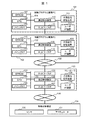
図1は、第1の実施の形態による産業用コントローラ(以下「コントローラ」とも呼ぶ)103及びプログラム開発環境のハードウェア構成の一例を示す。制御プログラム開発PC101、情報プログラム開発PC102、及び産業用コントローラ(以下単に「コントローラ」という)103は、基本的にほぼ同様のハードウェア構成を有し、後述するように目的に応じたソフトウェアが動作している。
(1) First Embodiment (1-1) Hardware Configuration FIG. 1 shows an example of the hardware configuration of the industrial controller (hereinafter, also referred to as “controller”) 103 and the program development environment according to the first embodiment. Is shown. The control program development PC 101, the information program development PC 102, and the industrial controller (hereinafter, simply referred to as “controller”) 103 basically have almost the same hardware configuration, and software according to the purpose operates as described later. ing.
ネットワーク105は、制御プログラム開発PC101、情報プログラム開発PC102及びコントローラ103を接続する。ネットワーク106は、コントローラ103及び制御対象機器104を接続する。
The
制御プログラム開発PC101は、制御プログラムを開発するためのコンピュータである。制御プログラム開発PC101は、EPROM107、CPU108、メインメモリ109、周辺制御装置110、ネットワークI/F111、不揮発性記憶装置112及びユーザI/F装置113を備えている。
The control program development PC 101 is a computer for developing a control program. The control program development PC 101 includes an EPROM 107, a
周辺制御装置110は、バス114を介して各種装置を相互に接続する。ネットワークI/F111は、ネットワーク105に接続するためのインターフェースである。不揮発性記憶装置112は、各種プログラムやファイルを格納する装置である。ユーザI/F装置113は、ユーザが必要なデータの入力等を行う装置である。
The
情報プログラム開発PC102は、情報プログラムを開発するためのコンピュータである。情報プログラム開発PC102は、EPROM115、CPU116、メインメモリ117、周辺制御装置118、ネットワークI/F119、不揮発性記憶装置120及びユーザI/F装置121を備えている。
The information program development PC 102 is a computer for developing an information program. The information program development PC 102 includes an EPROM 115, a
周辺制御装置118は、バス132を介して各種装置を相互に接続する。ネットワークI/F119は、ネットワーク105に接続するためのインターフェースである。不揮発性記憶装置120は、各種プログラムやファイルを格納する装置である。ユーザI/F装置121は、ユーザが必要なデータの入力等を行う装置である。
The
コントローラ103は、EPROM122、CPU123、メインメモリ124、周辺制御装置126、ネットワークI/F125、ネットワークI/F127、不揮発性記憶装置128及びユーザI/F装置129を備えている。
The
周辺制御装置126は、バス133を介して各種装置を相互に接続する。ネットワークI/F125、127は、各々対応するネットワーク105、106に接続するためのインターフェースである。不揮発性記憶装置128は、各種プログラムやファイルを格納する装置である。ユーザI/F装置129は、ユーザが必要なデータの入力等を行う装置である。
The
コントローラ103では、EPROM122又は不揮発性記憶装置128に格納されているオペレーティングシステム(OS)、各種プログラム及び各種ファイルをメインメモリ124に展開することにより、CPU123を用いて各種の演算等を実行する。
The
制御対象機器104は、センサ130及びアクチュエータ131を含んでいる。センサ130は、例えば、手動スイッチ、リレー、光電スイッチ、近接スイッチ、リミットスイッチ、重量計、温度センサ、圧力センサ、振動センサ、音波センサ、流量計、流速計、ガスセンサ、速度センサ、回転計、電流計、電圧計、電力計、水質センサ、色判別センサ、またはカメラのようなデバイスである。
The controlled
一方、アクチュエータ131は、例えば、モータ、発電機、ヒーター、制御弁、シリンダ、ソレノイド、ランプ、表示器、ブザー、スピーカー、ポンプ、圧縮機、空調機、冷凍機、またはコンベアのようなデバイスである。
On the other hand, the
(1−2)ソフトウェア構成
図2は、第1の実施の形態によるコントローラ103及びプログラム開発環境のソフトウェア構成の一例を示す。なお、図示の例では、図1における制御対象機器104が省略されている。
(1-2) Software Configuration FIG. 2 shows an example of the software configuration of the
本実施の形態では、制御プログラム207を実行するタスク処理の最後に共有アクセス部208が共有記憶領域224にアクセスする場合を例示している。なお、制御プログラムにグローバル変数が含まれる場合は、最高優先度のタスクがこのグローバル変数を共有記憶領域224に書き込む。
In the present embodiment, a case where the shared
(1−2−1)制御プログラム開発PC
まず、制御プログラム開発PC101について説明する。ソースファイル201は、制御プログラム207のソースコードが記述されたファイルである。エディタ202は、ソースファイル201を作成するためのプログラムである。コンパイラ203は、ソースファイル201から中間言語ファイルを作成する。リンカ204は、中間言語ファイルとライブラリ205を結合して実行ファイルを生成する。ライブラリ205は、プログラムの関数を再利用するために予め準備されている中間言語ファイルである。
(1-2-1) Control program development PC
First, the control program development PC 101 will be described. The
IDE制御部206は、エディタ202、コンパイラ203及びリンカ204等を制御するプログラムである。なお、エディタ202、コンパイラ203、リンカ204、ライブラリ205及びIDE制御部206をまとめて、統合開発環境プログラム(IDE:Integrated Development Environment)と呼ぶ。
The IDE control unit 206 is a program that controls the
さらに制御プログラム開発PC101は、共有アクセス部208、ヘッダファイル209、マップファイル210、共有領域アクセス部211及び連携ファイル生成部212を備えている。共有領域アクセス部211は、制御プログラム207が共有記憶領域224へアクセスするための共有アクセス部208のソースファイルである。連携ファイル生成部212は、ヘッダファイル209及びマップファイル210を生成する。
Further, the control
(1−2−2)情報プログラム開発コンピュータ
次に、情報プログラム開発PC102について説明する。ソースファイル213は、情報プログラム219のソースコードが記述されたファイルである。エディタ214は、ソースファイル213を作成するためのプログラムである。コンパイラ215は、ソースファイル213から中間言語ファイルを作成する。リンカ216は、中間言語ファイルとライブラリ217を結合して実行ファイルを生成する。ライブラリ217は、プログラムの関数を再利用するために予め準備されている中間言語ファイルである。
(1-2-2) Information Program Development Computer Next, the information
なお、上述したコントローラ103においては、複雑な算術演算、SCADA、MES、クラウドシステムとの情報の送受信のようなデータ処理が必要な場合がある。このようなデータ処理は、前述の制御装置特有の言語でプログラミングすることが困難な場合があり、C言語やJava(登録商標)言語などの情報通信分野で使われるプログラミング言語を用いて記述する場合がある。このようなデータ処理を実行するプログラムを「情報プログラム」と呼ぶ。この情報プログラムは、例えば情報プログラム219に相当する。
In the
IDE制御部218は、エディタ214、コンパイラ215及びリンカ216等を制御するプログラムである。なお、エディタ214、コンパイラ215、リンカ216、ライブラリ217及びIDE制御部218をまとめて、統合開発環境プログラムと呼ぶ。
The
さらに情報プログラム開発PC102は、共有アクセス部220、ヘッダファイル209及び連携ファイルアクセス部222を備えている。共有アクセス部220は、情報プログラム219が共有記憶領域224へアクセスするためのプログラムである。連携ファイルアクセス部222は、ヘッダファイル209をコントローラ103から取得したり、情報プログラム219と共有アクセス部220をコントローラへ送信したりする。
Further, the information
(1−2−3)コントローラ
一方、コントローラ103は、シーケンス制御装置、モーション制御装置またはプログラマブル・ロジック・コントローラ(PLC)とも呼ばれる。コントローラ103は、ラダー・ロジック(LD言語)、シーケンシャル・ファンクション・チャート(FC言語)、ファンクション・ブロック(FBD言語)、ストラクチャード・テキスト(ST言語)、またはインストラクション・リスト(LD言語)のような制御装置特有のプログラミング言語で制御内容が記述されたプログラムを実行する。
(1-2-3) Controller On the other hand, the
このような制御内容が実行可能なプログラムを「制御プログラム」と呼ぶ。制御プログラム207においては一連の処理をタスクと呼び、タスクごとに繰り返し処理する周期を設定できる。制御プログラム207において使用する変数には、入力専用変数及び出力専用変数が存在する。コントローラ103は、このような制御プログラム207のみならず、情報プログラム219も実行する。
A program capable of executing such control contents is called a "control program". In the
共有アクセス部208は、制御プログラム207が共有記憶領域224へアクセスするためのプログラムである。ライブラリ223は、制御プログラム207や共有アクセス部208が実行するために必要な共有関数の処理を実行する。ライブラリ226は、情報プログラム219が共有記憶領域224にアクセスするために、マップファイル210を参照してアクセス関数の処理を実行する。構成アクセス部229は、連携ファイルアクセス部222へヘッダファイル209を送信したり、連携ファイルアクセス部222から情報プログラム219と共有アクセス部220を受信したりする。タスクスケジューラ228は、タスクを実行する。タスクは、設定されている周期でそのタスクに登録されているプログラムを実行する。タスクに制御プログラム207と共有アクセス部208が登録されている場合、タスクは、実行周期に合わせて制御プログラム207と共有アクセス部208を実行する。共有記憶領域224は、制御プログラム207と情報プログラム219が共有する変数のデータを保存する。共有アクセス部220は、ライブラリ226を経由して共有記憶領域224にアクセスし、例えば、情報プログラム219の読み込み用構造体401にデータを読み込んだり、書き込み用構造体402のデータを共有記憶領域224の連続したアドレスの領域に書き込んだりする。
The shared
ヘッダファイル209は、連携ファイル生成部212が生成する情報プログラム219を作成する際に用いられるヘッダファイルである。マップファイル210は、連携ファイル生成部212が生成する情報プログラム219が共有記憶領域224へアクセスするために使用するファイルである。
The
コンテナ処理部227は、制御プログラム207と情報プログラム219とが互いに影響を及ぼさないようにするためのプログラムである。
The
(1−3)共有変数の設定画面
図3は、第1の実施の形態による共有変数の設定画面としての共有変数設定部301の一例を示す。なお、この共有変数設定部301は、制御プログラム開発PC101によって表示される、設定受け付け画面である。
(1-3) Shared variable setting screen FIG. 3 shows an example of the shared
共有変数設定部301は、情報プログラム219と共有する変数を設定するためのGUI(Graphic Use Interface)で、連携ファイル生成部212が生成する。共有チェック欄302は、チェックした場合には、変数名303に示す変数について情報プログラム219と変数を共有し、チェックしない場合にはそれについて情報プログラム219と変数共有しないことを表す。変数名303は、情報プログラムと共有する変数名である。型304は、変数の型である。周期305は、共有記憶領域224において共有される変数データを保存する周期を設定するための欄である。
The shared
キャンセルボタン306は、押下すると、共有変数設定部301での作業を破棄し終了する一方、OKボタン307は、押下すると、設定された情報を基にヘッダファイル209及びマップファイル210を生成する。アクセス権限308は、情報プログラムに付与するアクセス権限を表している。情報プログラムは、このアクセス権限308が「Read」であれば、変数名303に対応する変数のデータを読み込むことができる一方、「Write」であればそれを書き込むこともできる。
When the cancel
(1−4)ヘッダファイル
図4は、情報プログラム219を作成するためのヘッダファイル209の一例を示す。読み込み用構造体401は、情報プログラム219が共有記憶領域224の読み込みオフセット値(読み込み領域)から読み込んだデータが格納される構造体である。書き込み用構造体402は、情報プログラム219が共有記憶領域224の書き込みオフセット値(書き込み領域)に書き込むデータが格納される構造体である。ヘッダファイルには、構造体に限らずプログラム言語で使用可能な変数の宣言を記載してもよい。共有すべき変数がない場合は、対象となるアクセス用変数の宣言は記載されない。
(1-4) Header File FIG. 4 shows an example of a
全体readアクセス関数403は、情報プログラム219がすべての読み込み用変数のデータを読み込むための関数である。関数の呼び出し時に共有記憶領域224の読み込み領域からprDataにデータを読み込む。全体writeアクセス関数404は、情報プログラム219がすべての書き込み用変数のデータを書き込むための関数である。関数の呼び出し時にpwDataから共有記憶領域224の書き込み領域にデータを書き込む。全体writeのreadアクセス関数405は、情報プログラム219がすべての書き込み用変数のデータを読み込むための関数である。readアクセス関数405は、関数の呼び出し時に共有記憶領域224の書き込み領域からpwDataにデータを読み込む。個別readアクセス関数406は、情報プログラム219が個々の読み込み用変数のデータを読み込むための関数である。個別writeアクセス関数407は、情報プログラム219が個々の書き込み用変数のデータを書き込み領域に書き込むための関数である。個別writeのreadアクセス関数408は、情報プログラム219が個々の書き込み用変数のデータを書き込み領域から読み込むための関数である。
The overall
(1−5)マップファイル
図5は、マップファイル210をCSV形式で生成した一例である。マップファイル210は、共有アクセス部220が共有記憶領域224にアクセスする際に使用される。
(1-5) Map file FIG. 5 shows an example in which the
共有記憶領域名501は、共有記憶領域224を識別するための名称である。例えばOSがLinux(登録商標)であれば共有記憶領域としてファイルを作成するため、そのファイルの保存位置を表す絶対パスを共有記憶領域名501とする。
The shared
サイズ502は、共有記憶領域224で保存しているデータのサイズである。読み込みオフセット503は、共有記憶領域224の先頭アドレスと、共有アクセス部220が読み込むためのデータが格納されている領域の先頭アドレスとの差を表す。
The
書き込みオフセット504は、共有記憶領域224の先頭アドレスと、共有アクセス部220がデータを書き込むための領域の先頭アドレスとの差を表す。型505は、共有記憶領域224に書き込む制御プログラム207で使用しているデータの型である。
The write offset 504 represents the difference between the start address of the shared
変数名506は、共有記憶領域224に書き込むデータが格納されている、制御プログラム207で使用している変数の名前である。変数オフセット507は、共有アクセス部220が読み込むためのデータが格納されている領域の先頭アドレスと、対象の変数のデータが格納されている領域の先頭アドレスとの差を表す。型508は、共有記憶領域224から読み込む制御プログラム207で使用しているデータの型である。
The variable name 506 is the name of the variable used in the
変数名509は、共有記憶領域224から読み込んだデータを格納する制御プログラム207で使用している変数の名称である。変数オフセット510は、共有アクセス部220が読み込むためのデータが格納されている領域の先頭アドレスと、対象の変数のデータが格納されている領域の先頭アドレスとの差を表す。型505から変数オフセット510の情報は、個別の変数のみにアクセスする場合や、必要に応じて構造体のアライメントの調整に使用する。例えば、複数の情報プログラム219がありプログラミング言語が異なる場合、構造体のメンバが保存される領域の構造がマップファイル210と異なる場合ある。その場合、対象言語用に作成されるライブラリ226は、対象言語の構造体のアライメントに合わせてオフセット値を算出し、共有記憶領域224にアクセスする。型のサイズは、ライブラリ226で型名とサイズの変換テーブルを保持していてもよいし、マップファイル210に記載しておいてもよい。
The variable name 509 is the name of the variable used in the
図6は、制御プログラム207用のコンテナ及び情報プログラム219用のコンテナのイメージ図である。図示の例では、図2の各構成と同一の符号が付してある構成は、ほぼ同様の機能を有しているため、以下では異なる点を中心として説明する。
FIG. 6 is an image diagram of a container for the
コンテナ処理部227は、制御プログラム207と情報プログラム219とが互いに影響を及ぼさないようにするために、制御プログラム207及び情報プログラム219のためのコンテナを作成する。
The
具体的には、コンテナ処理部227は、制御プログラム207と情報プログラム219とがそれぞれ専用で使用するプロセス、ファイルシステム及びネットワークの名前空間と、CPU123とメインメモリ124とのリソースを作成する。
Specifically, the
本実施の形態では、制御プログラム207用のコンテナを「制御コンテナ」と呼ぶ一方、情報プログラム219用のコンテナを「情報コンテナ」と呼ぶことにする。コンテナの具体的な作成方法については後述する。
In the present embodiment, the container for the
図7は、制御プログラム207に関連する処理の一例を示す。まず、ステップS600では、コンテナ処理部227が、図6に示すように、制御プログラム207用の制御コンテナ及び情報プログラム219用の情報コンテナを作成する。
FIG. 7 shows an example of processing related to the
図6コンテナ処理部227は、共有記憶領域224が作成されるディレクトリを制御コンテナ及び情報コンテナのファイルシステムにマウント(図示の点線に相当)して共有ディレクトリを作成し、制御プログラム207と情報プログラム219からアクセスできるようにする。また、コンテナ処理部227は、ヘッダファイル209とマップファイル210を保存するための共有ディレクトリと、情報プログラム219及び共有アクセス部220を保存するための共有ディレクトリも作成する。その際、コンテナ処理部227は、後者の共有ディレクトリについては、情報コンテナのファイルシステムにのみマウントして共有する。制御プログラム207は制御コンテナ内で実行され、情報プログラム219は情報コンテナ内で実行される。
FIG. 6 The
ステップS601では、ユーザが、制御プログラム開発PC101を用いて、既述のIDEを使用してソースコードをまとめて管理するためのプロジェクトを作成し、制御プログラム207を作成する。ステップS602では、ユーザが、共有変数設定部301を起動するために、既述のIDEの該当するメニューを選択する。選択されると、連携ファイル生成部212がソースファイル201から変数を抽出する。
In step S601, the user creates a project for collectively managing the source code using the IDE described above using the control
ステップS603では、連携ファイル生成部212が、共有変数設定部301(図3参照)を生成して表示する。ユーザは、情報プログラム219と共有する変数の共有チェック欄302にチェックし、アクセス権限308及び周期305を設定する。設定が完了した後、ユーザがOKボタン307を押下すると、連携ファイル生成部212は、設定内容をメモリに保存する。
In step S603, the cooperation
ステップS604では、連携ファイル生成部212が、設定された値をメモリから取得する。
In step S604, the cooperation
ステップS605では、連携ファイル生成部212がヘッダファイル209及びマップファイル210を生成する。連携ファイル生成部212は、アクセス権限308が「Read」に設定された変数を読み込み用構造体401としてヘッダファイル209に定義する。次に連携ファイル生成部212は、アクセス権限308が「Write」に設定された変数を書き込み用構造体402としてヘッダファイル209に定義する。そして、連携ファイル生成部212は、全体readアクセス関数403、全体writeアクセス関数404、全体writeのreadアクセス関数405、個別readアクセス関数406、個別writeアクセス関数407および個別writeのreadアクセス関数408をヘッダファイル209に定義する。
In step S605, the cooperation
次に連携ファイル生成部212は、情報プログラム219がヘッダファイル209に定義された構造体変数の構造で共有記憶領域224にアクセスできるようにマップファイル210を生成する。具体的には、連携ファイル生成部212は、共有記憶領域名501、共有記憶領域名で生成するファイルのサイズ502、読み込みオフセット503、及び書き込みオフセット504をマップファイル210に出力する。連携ファイル生成部212は、共有記憶領域224の先頭アドレスから順に「Read」に設定された変数を保存し、連続して「Write」に設定された変数を保存できるように共有記憶領域224にアクセスするためのマップファイル210を生成する。連携ファイル生成部212は、ヘッダファイル209で定義した構造体のサイズからサイズ502、読み込みオフセット503、書き込みオフセット504を算出する。次に連携ファイル生成部212は、読み込み用構造体401定義されている変数の型505、変数名506、変数オフセット507をマップファイル210に出力する。次に連携ファイル生成部212は、書き込み用構造体402定義されている変数の型508、変数名509、変数オフセット510をマップファイル210に出力する。連携ファイル生成部212は、変数オフセット(507と510)を変数の定義順序、変数のサイズ、および情報プログラム219の構造体のアライメントを考慮して算出して出力する。
Next, the cooperation
ステップS606では、連携ファイル生成部212は、共有記憶領域224の名前を決定して共有記憶領域224を作成し、この共有記憶領域224で共有変数のデータを保存する領域にアクセスできるソースコード(共有領域アクセス部211)を生成する。具体的には、連携ファイル生成部212は、ヘッダファイル209に定義する構造体の変数の順番、マップファイル210に出力したオフセットを基にして、共有変数設定部301において、「Read」に設定された読み込み用変数のデータを共有記憶領域224に書き込むソースコードと、「Write」に設定された書き込み用変数のデータを共有記憶領域224から制御プログラム207の変数に読み込むソースコードを生成する。
In step S606, the cooperation
連携ファイル生成部212は、制御プログラム207をタスクに登録し、タスクの実行周期として周期305を設定する。タスクの実行周期は、制御プログラム作成者等により手動で設定されてもよい。連携ファイル生成部212は、制御プログラム207の次に実行されるように共有記憶領域224にアクセスする共有アクセス部208を同じタスクに登録する。
The cooperation
ステップS607では、ユーザが既述のIDEで実行メニューを選択すると、IDE制御部206はソースコードをビルドし、制御プログラム207及び共有アクセス部208を生成する。
In step S607, when the user selects the execution menu in the IDE described above, the IDE control unit 206 builds the source code and generates the
ステップS608では、制御プログラム開発PC101においてIDE制御部206が、制御プログラム207及び共有アクセス部208を既述の制御コンテナ内の共有ディレクトリ以外の場所に送信し、ヘッダファイル209及びマップファイル210を制御コンテナ内の共有ディレクトリに送信する。
In step S608, in the control
ステップS609では、IDE制御部206が、コントローラ103のタスクスケジューラ228を実行する。ステップS610では、タスクスケジューラ228がタスクを実行し、タスクは設定された実行周期で制御プログラム207を実行する。制御プログラム207は、制御処理を実行する。一度起動したタスクは、周期的に登録されたプログラムを実行するため再度タスクスケジューラからは実行されない。
In step S609, the IDE control unit 206 executes the
ステップS611では、タスクが制御プログラム207の実行後に共有アクセス部208を実行する。ステップS612では、共有アクセス部220が、ライブラリ223の処理も活用しつつ共有記憶領域名501とサイズ502を指定して共有記憶領域224をオープン(アクセス可能な状態)し、マップファイル210に出力した情報を基にRead権限の変数のデータを書き込む一方、Write権限の変数のデータを読み込む。次にステップS610が実行される。
In step S611, the task executes the shared
図8は、情報プログラム219の関連処理の一例を示す。ステップS701では、ユーザが既述のIDEを使用してソースコードをまとめて管理するためのプロジェクトを作成するウィザードを実行する。
FIG. 8 shows an example of related processing of the
ステップS702では、ウィザードが実行されると、IDE制御部218は、連携ファイルアクセス部222を実行してコントローラ103の構成アクセス部229と通信し、ヘッダファイル209を取得する。
In step S702, when the wizard is executed, the
ステップS703では、連携ファイルアクセス部222が、情報プログラム219のソースコードとなるファイルのヘッダファイル宣言部の位置にヘッダファイル209の宣言を入力してプロジェクトの作成が完了する。
In step S703, the cooperation
ステップS704では、ユーザが、情報プログラム219と、共有記憶領域224へアクセスするための共有アクセス部220のソースコードとを作成する。ユーザは、ヘッダファイル209に定義された関数を基にして、共有アクセス部220のソースコードを作成する。
In step S704, the user creates the
ステップS705では、ユーザが既述のIDEで実行メニューを選択すると、IDE制御部218はソースコードをビルドし、情報プログラム219及び共有アクセス部220を生成する。共有アクセス部220は、情報プログラム219に含まれていてもよい。
In step S705, when the user selects the execution menu in the IDE described above, the
ステップS706では、連携ファイルアクセス部222が、情報プログラム219及び共有アクセス部220を構成アクセス部229に送信する。コンテナ処理部227は、構成アクセス部229が情報プログラム219及び共有アクセス部220を受信したときに、情報コンテナを作成してもよい。コンテナ処理部227は、情報プログラム219が終了したときに情報コンテナを削除してもよい。構成アクセス部229は、情報プログラム219及び共有アクセス部220を情報コンテナ内からアクセスできる共有ディレクトリに保存する。本実施の形態では、構成アクセス部229を介して情報コンテナ内に情報プログラム219と共有アクセス部220を保存したが、連携ファイルアクセス部222が情報コンテナ内のFTPサーバ等と通信して情報コンテナ内に情報プログラム219と共有アクセス部220を保存してもよい。ステップS707では、IDE制御部218が、例えばSSH接続で情報コンテナ内にログインして情報プログラム219を実行する。
In step S706, the linked
ステップS708では、情報プログラム219がデータ処理を実行する。ステップS709では、情報プログラム219が共有アクセス部220を実行する。ステップS710では、共有アクセス部220がアクセス関数を実行するために、ライブラリ226を呼び出す。ライブラリ226は、共有ディレクトリからマップファイル210を取得する。ライブラリ226は、あらかじめマップファイル210を取得するためのパス名を保持している。
In step S708, the
ステップS711では、共有アクセス部220が、ライブラリ226経由で共有記憶領域224へのアクセスを実行する。
In step S711, the shared
(1−6)アクセス方法 (1−6−1)全体readアクセス:
ライブラリ226は、関数の引数から読み込み用構造体401の先頭アドレスを取得する。ライブラリ226は、書き込みオフセット504と読み込みオフセット503の差から読み込むデータサイズを算出する。ライブラリ226は、共有記憶領域名501を指定して共有記憶領域224をオープンし、読み込みオフセット503の位置から算出したサイズ分のデータを読み込み、取得した読み込み用構造体401の先頭アドレスから順に読み込んだデータを書き込む。
(1-6) Access method (1-6-1) Whole read access:
(1−6−2)全体writeアクセス:
ライブラリ226は、関数の引数から書き込み用構造体402の先頭アドレスを取得する。ライブラリ226は、サイズ502と書き込みオフセット504の差から書き込むデータサイズを算出する。ライブラリ226は、共有記憶領域名501を指定して共有記憶領域224をオープンし、書き込み用構造体402の先頭アドレスの位置から算出したサイズ分のデータを読み込み、共有憶領域224の書き込みオフセット503の位置から読み込んだデータを順に書き込む。
(1-6-2) Whole write access:
(1−6−3)全体writeのreadアクセス:
ライブラリ226は、関数の引数から書き込み用構造体402の先頭アドレスを取得する。ライブラリ226は、サイズ502と書き込みオフセット504の差から読み込むデータサイズを算出する。ライブラリ226は、共有記憶領域名501を指定して共有記憶領域224をオープンし、書き込みオフセット503の位置から算出したサイズ分のデータを読み込み、取得した書き込み用構造体402の先頭アドレスから順に読み込んだデータを書き込む。
(1-6-3) Read access for whole write:
(1−6−4)個別readアクセス:
ライブラリ226は、関数の引数から読み込み用構造体401の先頭アドレスと個別変数の先頭アドレスを取得する。ライブラリ226は、取得したアドレスの差を計算して個別変数のオフセット値を算出する。ライブラリ226は、マップファイル210を参照し、一致する変数オフセット507の変数を特定する。ライブラリは、特定した変数の型505からサイズを特定する。ライブラリ226は、共有記憶領域名501を指定して共有記憶領域224をオープンし、読み込みオフセット503の位置から算出したオフセット分だけ離れた位置から特定したサイズ分のデータを読み込み、取得した個別変数の先頭アドレスから順に、読み込んだデータを書き込む。
(1-6-4) Individual read access:
The
(1−6−5)個別writeアクセス:
ライブラリ226は、関数の引数から書き込み用構造体402の先頭アドレスと個別変数の先頭アドレスを取得する。ライブラリ226は、取得したアドレスの差と書き込みオフセット504を足して個別変数のオフセット値を算出する。ライブラリ226は、マップファイル210を参照し、算出したオフセット値と一致する変数オフセット510の変数を特定する。ライブラリ226は、特定した変数の型508からサイズを特定する。ライブラリ226は、共有記憶領域名501を指定して共有記憶領域224をオープンし、個別変数の先頭アドレスから特定したサイズ分のデータを読み込み、共有記憶領域224の先頭アドレスから算出したオフセット分だけ離れた位置から、個別変数の先頭アドレスから読み込んだデータを書き込む。
(1-6-5) Individual write access:
The
(1−6−6)個別writeのreadアクセス:
ライブラリ226は、関数の引数から書き込み用構造体402の先頭アドレスと個別変数の先頭アドレスを取得する。ライブラリ226は、取得したアドレスの差に書き込みオフセット504を足して個別変数のオフセット値を算出する。ライブラリ226は、マップファイル210を参照し、変数オフセット510の差が一致する変数を特定する。ライブラリ226は、特定した変数の型508からサイズを特定する。ライブラリ226は、共有記憶領域名501を指定して共有記憶領域224をオープンし、算出したオフセット分だけ離れた位置から特定したサイズ分のデータを読み込み、取得した個別変数の先頭アドレスから順に、読み込んだデータを書き込む。
(1-6-6) Read access for individual write:
The
次にステップS708を実行する。共有アクセス部208とライブラリ226が共有記憶領域224に書き込む処理は、書き込み処理が中断されず連続した処理となるアトミック処理とする。
Next, step S708 is executed. The process of writing to the shared
(1−7)本実施の形態の作用効果等
以上のような構成によれば、制御プログラム207に含まれる共有変数の変数情報が抽出され、共有記憶領域224に関するマップファイル210と、共有記憶領域224へのアクセスの際に使用されるヘッダファイル209とが作成される。また、ヘッダファイル209を用いて情報プログラム219が生成される。この情報プログラム219は、マップファイル210を用いて共有記憶領域224にアクセスする。このようにすると、制御プログラム207と情報プログラム219との間で同一の共有変数名が自動的に生成されることになり、管理者の手動による、制御プログラム209の制御対象機器であるデバイスのアドレスの割り当て作業を必要としなくなるため、開発効率を向上することができる。
(1-7) Actions and effects of the present embodiment According to the above configuration, the variable information of the shared variables included in the
(2)第2の実施の形態
第2の実施の形態では、第1の実施の形態と同様の構成及び動作については説明を省略し、異なる点を中心として説明する。第2の実施の形態では、第1の実施の形態とは異なり、制御プログラム207のタスクとは別のタスクとして共有アクセス部208が実行され、共有記憶領域224にアクセスする。
(2) Second Embodiment In the second embodiment, the same configuration and operation as those of the first embodiment will be described by omitting the description and focusing on the differences. In the second embodiment, unlike the first embodiment, the shared
図9は、制御プログラム関連の処理の一例を示す。ステップS801では、連携ファイル生成部212が、共有記憶領域224の名前を決定し、共有記憶領域224を作成し、共有変数のデータを共有記憶領域224にアクセスできるソースコード(共有領域アクセス部211)を生成する。連携ファイル生成部212は、制御プログラム207のタスクとは別の共有アクセスタスクを作成し、実行する周期として共有変数設定部301から取得した周期を設定する。連携ファイル生成部212は、制御プログラム207を実行するタスクの優先度よりも共有アクセスタスクの実行優先度を低く設定する。
FIG. 9 shows an example of control program related processing. In step S801, the linked
ステップS802では、タスクスケジューラ228が、タスクを実行し、タスクは設定された実行周期で登録されている制御プログラム207を実行する。制御プログラム207は、制御処理を実行する。次にステップS803が実行される。このタスクは、設定された実行周期で制御プログラム207を繰り返し実行する。ステップS803では、タスクスケジューラ228が共有アクセスタスクを実行し、共有アクセスタスクが登録されている共有アクセス部208を実行する。次にステップS612を実行する。この共有アクセスタスクは、設定された実行周期でステップ803とステップ612を繰り返し実行する。
In step S802, the
以上のような構成によれば、制御プログラム207のタスクとは独立した共有アクセス部208が、制御プログラム207より実行優先度が低い状態で共有記憶領域224にアクセスするため、制御プログラム207の影響を受けにくくすることができる。
According to the above configuration, the shared
(3)その他の実施形態
上記実施形態は、本発明を説明するための例示であり、本発明をこれらの実施形態にのみ限定する趣旨ではない。本発明は、その趣旨を逸脱しない限り、様々な形態で実施することができる。例えば、上記実施形態では、各種プログラムの処理をシーケンシャルに説明したが、特にこれにこだわるものではない。従って、処理結果に矛盾が生じない限り、処理の順序を入れ替え又は並行動作するように構成しても良い。
(3) Other Embodiments The above-described embodiments are examples for explaining the present invention, and the present invention is not intended to be limited only to these embodiments. The present invention can be implemented in various forms as long as it does not deviate from the gist thereof. For example, in the above embodiment, the processing of various programs has been described sequentially, but the present invention is not particularly particular. Therefore, as long as there is no contradiction in the processing results, the processing order may be changed or the processing may be configured to operate in parallel.
本発明は、いわゆるプログラマブルロジックコントローラを組み込んだ機器としての産業用コントローラ及び産業用コントローラにおけるデータ共有方法に広く適用することができる。 The present invention can be widely applied to an industrial controller as a device incorporating a so-called programmable logic controller and a data sharing method in the industrial controller.
101……制御プログラム開発PC、102……情報プログラム開発PC、103……コントローラ、104……制御対象機器、130……センサ、131……アクチュエータ。 101 ... Control program development PC, 102 ... Information program development PC, 103 ... Controller, 104 ... Control target device, 130 ... Sensor, 131 ... Actuator.
Claims (8)
前記制御プログラム開発コンピュータは、
前記制御プログラムに含まれる前記共有変数の変数情報を抽出し、前記共有記憶領域に関するマップファイルと、前記共有記憶領域へのアクセスの際に使用されるヘッダファイルとを作成するファイル作成部を備え、
前記情報プログラム開発コンピュータは、
前記ヘッダファイルを用いて前記情報プログラムを生成するプログラム作成部を備え、
前記産業用コントローラが実行する前記情報プログラムは、
前記マップファイルを用いて前記共有記憶領域にアクセスする
ことを特徴とするプログラム開発システム。 And an industrial controller to the information program for executing a control program and Jo Tokoro of a process for the control target device to share data in the shared memory area by using the shared variable, and the information programmable develop information program development computer , An industrial controller program development system having a control program development computer capable of developing the control program .
The control program development computer
It is provided with a file creation unit that extracts variable information of the shared variable included in the control program and creates a map file related to the shared storage area and a header file used when accessing the shared storage area.
The information program development computer is
A program creation unit that generates the information program using the header file is provided.
The information program executed by the industrial controller is
A program development system characterized in that the shared storage area is accessed using the map file.
前記共有記憶領域にアクセスするための共有アクセス部を作成して前記情報プログラムを生成し、
前記情報プログラムは、
前記共有アクセス部を呼び出して前記共有記憶領域へのアクセスを行う
ことを特徴とする請求項1に記載のプログラム開発システム。 The program creation unit
A shared access unit for accessing the shared storage area is created to generate the information program, and the information program is generated.
The information program
The program development system according to claim 1, wherein the shared access unit is called to access the shared storage area.
前記情報プログラムが前記共有記憶領域から読み込んだデータが格納される読み込み用変数宣言と、
前記情報プログラムが前記共有記憶領域に書き込むデータが格納される書き込み用変数宣言と、
前記情報プログラムが前記共有変数に対してアクセスするためのアクセス関数と、
を含むことを特徴とする請求項1に記載のプログラム開発システム。 The header file is
A variable declaration for reading in which the data read by the information program from the shared storage area is stored, and
A variable declaration for writing in which the data to be written by the information program in the shared storage area is stored, and
An access function for the information program to access the shared variable,
The program development system according to claim 1, wherein the program development system comprises .
少なくとも1つの前記共有記憶領域を互いに識別するための共有記憶領域名と、
少なくとも1つの前記共有記憶領域のサイズと、
少なくとも1つの前記共有記憶領域の先頭アドレスと、前記共有アクセス部が読み込むためのデータが格納されている領域の先頭アドレスとの差である読み込みオフセットと、
少なくとも1つの前記共有記憶領域の先頭アドレスと、前記共有アクセス部がデータを書き込むための領域の先頭アドレスとの差である書き込みオフセットと、
前記共有変数のうち読み込み変数に関する読み込み変数情報と、
前記共有変数のうち書き込み変数に関する書き込み変数情報と、
を含むことを特徴とする請求項2に記載のプログラム開発システム。 The map file is
A shared storage area name for identifying at least one shared storage area from each other, and
The size of at least one of the shared storage areas and
A read offset, which is the difference between the start address of at least one shared storage area and the start address of the area in which the data to be read by the shared access unit is stored.
A write offset, which is the difference between the start address of at least one shared storage area and the start address of the area for the shared access unit to write data.
Read variable information about read variables among the shared variables and
Write variable information about write variables among the shared variables and
The program development system according to claim 2, wherein the program development system comprises .
前記共有変数に関する設定を受付可能な画面を表示することを特徴とする請求項1に記載のプログラム開発システム。 Before Symbol control program development computer,
The program development system according to claim 1, wherein a screen capable of accepting settings related to the shared variable is displayed.
前記制御プログラム開発コンピュータが、前記制御プログラムに含まれる前記共有変数の変数情報を抽出し、前記共有記憶領域に関するマップファイルと、前記共有記憶領域へのアクセスの際に使用されるヘッダファイルとを作成するファイル作成ステップと、
前記情報プログラム開発コンピュータが前記ヘッダファイルを用いて前記情報プログラムを生成するプログラム作成ステップと、
前記産業用コントローラが実行する前記情報プログラムが前記マップファイルを用いて前記共有記憶領域にアクセスするデータアクセスステップと、
を有することを特徴とするデータ共有方法。 And an industrial controller to the information program for executing a control program and Jo Tokoro of a process for the control target device to share data in the shared memory area by using the shared variable, and the information programmable develop information program development computer , A data sharing method in a program development system of an industrial controller having a control program development computer capable of developing the control program .
The control program development computer extracts the variable information of the shared variable included in the control program, and creates a map file related to the shared storage area and a header file used when accessing the shared storage area. File creation steps and
A program creation step in which the information program development computer generates the information program using the header file, and
A data access step in which the information program executed by the industrial controller accesses the shared storage area using the map file.
Features and to Lud over data sharing method to have a.
前記情報プログラム開発コンピュータが、前記共有記憶領域にアクセスするための共有アクセス部を作成して前記情報プログラムを生成し、
前記産業用コントローラが実行する前記情報プログラムは、
前記共有アクセス部を呼び出して前記共有記憶領域へのアクセスを行う
ことを特徴とする請求項7に記載のデータ共有方法。 In the program creation step,
The information program development computer creates a shared access unit for accessing the shared storage area and generates the information program.
The information program executed by the industrial controller is
Data sharing method according to claim 7, characterized in that access to said shared storage area by calling the shared access unit.
Priority Applications (5)
| Application Number | Priority Date | Filing Date | Title |
|---|---|---|---|
| JP2017088962A JP6821497B2 (en) | 2017-04-27 | 2017-04-27 | Data sharing method in the program development system of the industrial controller and the program development system of the industrial controller |
| CN201780085749.2A CN110249274B (en) | 2017-04-27 | 2017-12-28 | Program development system for industrial controller and data sharing method thereof |
| EP17907828.2A EP3617819B1 (en) | 2017-04-27 | 2017-12-28 | Industrial controller and data sharing method in an industrial controller |
| US16/487,538 US10955809B2 (en) | 2017-04-27 | 2017-12-28 | Industrial controller and data sharing method of industrial controller |
| PCT/JP2017/047400 WO2018198439A1 (en) | 2017-04-27 | 2017-12-28 | Industrial controller and data sharing method in industrial controller |
Applications Claiming Priority (1)
| Application Number | Priority Date | Filing Date | Title |
|---|---|---|---|
| JP2017088962A JP6821497B2 (en) | 2017-04-27 | 2017-04-27 | Data sharing method in the program development system of the industrial controller and the program development system of the industrial controller |
Publications (2)
| Publication Number | Publication Date |
|---|---|
| JP2018185772A JP2018185772A (en) | 2018-11-22 |
| JP6821497B2 true JP6821497B2 (en) | 2021-01-27 |
Family
ID=63920357
Family Applications (1)
| Application Number | Title | Priority Date | Filing Date |
|---|---|---|---|
| JP2017088962A Active JP6821497B2 (en) | 2017-04-27 | 2017-04-27 | Data sharing method in the program development system of the industrial controller and the program development system of the industrial controller |
Country Status (5)
| Country | Link |
|---|---|
| US (1) | US10955809B2 (en) |
| EP (1) | EP3617819B1 (en) |
| JP (1) | JP6821497B2 (en) |
| CN (1) | CN110249274B (en) |
| WO (1) | WO2018198439A1 (en) |
Families Citing this family (15)
| Publication number | Priority date | Publication date | Assignee | Title |
|---|---|---|---|---|
| JP6922583B2 (en) * | 2017-09-15 | 2021-08-18 | オムロン株式会社 | Information processing equipment, information processing methods, and information processing programs |
| JP6922793B2 (en) * | 2018-03-12 | 2021-08-18 | オムロン株式会社 | Control devices, control methods, and control programs |
| JP6969460B2 (en) * | 2018-03-15 | 2021-11-24 | オムロン株式会社 | Program development support system, program development support method and program development support program |
| JP6950634B2 (en) * | 2018-07-03 | 2021-10-13 | オムロン株式会社 | Control device and control method |
| JP6950635B2 (en) * | 2018-07-03 | 2021-10-13 | オムロン株式会社 | Compilation device and compilation method |
| JP7141939B2 (en) * | 2018-12-13 | 2022-09-26 | 株式会社日立産機システム | industrial controller |
| CN111913426B (en) * | 2019-05-08 | 2023-05-05 | 创升益世(东莞)智能自控有限公司 | Software container method applied to industrial automation control system |
| JP7294078B2 (en) * | 2019-11-12 | 2023-06-20 | オムロン株式会社 | Control device |
| JP6787616B1 (en) * | 2020-01-28 | 2020-11-18 | 株式会社オプトン | Control program generator, control program generation method, program |
| JP6829505B1 (en) * | 2020-04-20 | 2021-02-10 | 株式会社オプトン | Control program generator, control program generation method, program |
| CN112596918A (en) * | 2020-12-04 | 2021-04-02 | 广东嘉腾机器人自动化有限公司 | Method for sharing variable between programs in system and storage device |
| CN116710857A (en) * | 2021-06-25 | 2023-09-05 | 三菱电机株式会社 | Input unit, control system, communication method, and program |
| CN113268043A (en) * | 2021-06-28 | 2021-08-17 | 华能鹤岗发电有限公司 | Method and device for realizing information exchange between PLC (programmable logic controller) and DCS (distributed control system) |
| CN114167845B (en) * | 2021-12-23 | 2023-12-05 | 广东嘉腾机器人自动化有限公司 | Communication offline diagnosis method and system for PLC and equipment |
| CN116483597B (en) * | 2023-06-25 | 2024-01-05 | 广东科伺智能科技有限公司 | Data sharing method, device, equipment and storage medium |
Family Cites Families (10)
| Publication number | Priority date | Publication date | Assignee | Title |
|---|---|---|---|---|
| US4570217A (en) * | 1982-03-29 | 1986-02-11 | Allen Bruce S | Man machine interface |
| JPH043205A (en) * | 1990-04-20 | 1992-01-08 | Yokogawa Electric Corp | Data access system |
| JP3548777B2 (en) * | 1998-10-28 | 2004-07-28 | オムロン株式会社 | Control device |
| DE112006003770T5 (en) * | 2006-03-29 | 2009-04-23 | Mitsubishi Electric Corporation | A programming support apparatus, a program support method, a program for causing a computer to implement the method, and a recording medium containing the program |
| CN101231525A (en) * | 2008-02-21 | 2008-07-30 | 四方电气(集团)有限公司 | Method for implementing DCS controller real-time data base of distributed control system |
| WO2012156775A1 (en) * | 2011-05-16 | 2012-11-22 | Abb Research Ltd | A method and a system for online and dynamic distribution and configuration of applications in a distributed control system |
| JP5079166B1 (en) * | 2011-07-01 | 2012-11-21 | 三菱電機株式会社 | Symbol table generation method, communication method with peripheral device, and programmable logic controller |
| US8832670B2 (en) * | 2011-07-01 | 2014-09-09 | Mitsubishi Electric Corporation | Programmable controller and programming tool for communication with legacy equipment |
| JP6292096B2 (en) * | 2014-04-24 | 2018-03-14 | 富士電機株式会社 | Programmable controller system and its support device |
| CN107703878B (en) * | 2015-11-27 | 2019-06-28 | 中工科安科技有限公司 | A kind of PLC distributed remote I/O expansion module |
-
2017
- 2017-04-27 JP JP2017088962A patent/JP6821497B2/en active Active
- 2017-12-28 CN CN201780085749.2A patent/CN110249274B/en active Active
- 2017-12-28 EP EP17907828.2A patent/EP3617819B1/en active Active
- 2017-12-28 US US16/487,538 patent/US10955809B2/en active Active
- 2017-12-28 WO PCT/JP2017/047400 patent/WO2018198439A1/en unknown
Also Published As
| Publication number | Publication date |
|---|---|
| EP3617819A1 (en) | 2020-03-04 |
| US20190369588A1 (en) | 2019-12-05 |
| CN110249274B (en) | 2022-04-19 |
| JP2018185772A (en) | 2018-11-22 |
| US10955809B2 (en) | 2021-03-23 |
| EP3617819A4 (en) | 2020-12-02 |
| CN110249274A (en) | 2019-09-17 |
| EP3617819B1 (en) | 2022-03-02 |
| WO2018198439A1 (en) | 2018-11-01 |
Similar Documents
| Publication | Publication Date | Title |
|---|---|---|
| JP6821497B2 (en) | Data sharing method in the program development system of the industrial controller and the program development system of the industrial controller | |
| EP3611618A1 (en) | Information processing device, information processing method, and computer program | |
| JP6950665B2 (en) | Engineering equipment, control methods and programs for engineering equipment | |
| JP2018129020A (en) | Method and apparatus for controlling and managing industrial processes using industrial internet operating system | |
| JP6292096B2 (en) | Programmable controller system and its support device | |
| WO2020246097A1 (en) | Support device and support program | |
| JP6135247B2 (en) | Information processing apparatus and information processing program | |
| US20240004688A1 (en) | Control system and control method | |
| JP6794668B2 (en) | Programming device | |
| JP6455096B2 (en) | Control system, its support device, programmable control device | |
| CN112685051A (en) | Method, device, platform and storage medium for automatically executing shell script | |
| JP4877257B2 (en) | Programmable controller, programmable controller support apparatus, and programmable controller system | |
| CN112639730A (en) | Method, device and system for writing and running processing of program file | |
| JP6295914B2 (en) | Programmable controller system, its support device, programmable controller | |
| JP2009157534A (en) | Programming support system, its programmable controller support device, and programmable indicator support device | |
| JP7234810B2 (en) | Support equipment and support programs | |
| US20220291903A1 (en) | Information processing device, recording medium, and support system | |
| JP7453315B2 (en) | Program, information processing device, information processing system, and information processing method | |
| US10977032B2 (en) | Assistance device, design assistance method and program | |
| US20220179375A1 (en) | Human-machine interface with imaging application | |
| CN110249590B (en) | Control system and path information generation method | |
| WO2015083234A1 (en) | Function call table generating device, program execution device, and execution program | |
| JP2014182711A (en) | Build tool |
Legal Events
| Date | Code | Title | Description |
|---|---|---|---|
| A621 | Written request for application examination |
Free format text: JAPANESE INTERMEDIATE CODE: A621 Effective date: 20191227 |
|
| A131 | Notification of reasons for refusal |
Free format text: JAPANESE INTERMEDIATE CODE: A131 Effective date: 20200721 |
|
| A521 | Request for written amendment filed |
Free format text: JAPANESE INTERMEDIATE CODE: A523 Effective date: 20200902 |
|
| TRDD | Decision of grant or rejection written | ||
| A01 | Written decision to grant a patent or to grant a registration (utility model) |
Free format text: JAPANESE INTERMEDIATE CODE: A01 Effective date: 20201208 |
|
| A61 | First payment of annual fees (during grant procedure) |
Free format text: JAPANESE INTERMEDIATE CODE: A61 Effective date: 20210106 |
|
| R150 | Certificate of patent or registration of utility model |
Ref document number: 6821497 Country of ref document: JP Free format text: JAPANESE INTERMEDIATE CODE: R150 |