EP3682841B2 - Dentales wurzelkanalinstrument - Google Patents
Dentales wurzelkanalinstrument Download PDFInfo
- Publication number
- EP3682841B2 EP3682841B2 EP20152244.8A EP20152244A EP3682841B2 EP 3682841 B2 EP3682841 B2 EP 3682841B2 EP 20152244 A EP20152244 A EP 20152244A EP 3682841 B2 EP3682841 B2 EP 3682841B2
- Authority
- EP
- European Patent Office
- Prior art keywords
- root canal
- core
- region
- canal instrument
- slope
- Prior art date
- Legal status (The legal status is an assumption and is not a legal conclusion. Google has not performed a legal analysis and makes no representation as to the accuracy of the status listed.)
- Active
Links
Images

Classifications
-
- A—HUMAN NECESSITIES
- A61—MEDICAL OR VETERINARY SCIENCE; HYGIENE
- A61C—DENTISTRY; APPARATUS OR METHODS FOR ORAL OR DENTAL HYGIENE
- A61C5/00—Filling or capping teeth
- A61C5/40—Implements for surgical treatment of the roots or nerves of the teeth; Nerve needles; Methods or instruments for medication of the roots
- A61C5/42—Files for root canals; Handgrips or guiding means therefor
Definitions
- the present invention relates to a dental root canal instrument for treating a root canal of a tooth.
- Root canal instruments are state of the art, for example from DE 202012012526 U1 Root canal instruments must have a certain flexibility in order to be able to follow the curves and turns of the root canal in order to be able to carry out a corresponding root canal treatment. Molars in particular can have a relatively complicated root canal system in which the root canal instrument must also follow small radii of the root canal. This must ensure sufficient flexibility of the root canal instrument. Therefore, root canal instruments have a core, i.e. a solid material core, starting from a tip of the root canal instrument, which continuously widens conically in the direction of a shaft area of the root canal instrument. The core of the root canal instrument has a very small diameter in cross-section at the tip, which continuously widens.
- a slope of the core runs over the entire length of the shaft area parallel to a slope of an outer envelope curve of the cutting edges of the cutting area. Furthermore, the DE 20 2012 012526 U1 and the WO 99/43469 A1 a root canal instrument according to the preamble of claim 1.
- the dental root canal instrument according to the invention with the features of claim 1 has the advantage that the root canal instrument has excellent flexibility.
- the bends and turns of the root canal can be followed excellently with the root canal instrument according to the invention.
- Dead or infected pulp tissue can thus be completely removed from the root canal with a high degree of reliability.
- the root canal can be prepared in a conical manner, with the narrowest point being at the apical end point of the root canal.
- the root canal instrument has a shaft area and a cutting area with at least one cutting edge and a core.
- the core (solid material core) of the root canal instrument is the area inside the root canal instrument around which the cutting edges and chip receiving grooves of the root canal instrument are guided. An envelope curve of the cutting edges runs from a tip to the
- the core of the cutting region has at least one core region which has a second slope in the direction of the shaft region of the root canal instrument, which is smaller than the first slope.
- the second slope of the core is smaller than the first slope of the envelope curve of the cutting edges.
- Root canal instruments usually have cores which widen conically in the direction of the shaft region with the same slope as the envelope curve of the cutting edges.
- the core widening in the direction of the shaft region with a small slope means that the root canal instrument has greater flexibility, in particular in the part of the cutting region which is closer to the shaft region.
- the core rises in stages towards the shaft region.
- One or more steps can be provided, the slopes at the respective step regions always being smaller than the slope of the envelope curve of the cutting edges.
- the core widens at a first conical region from the tip to a first point P1, which is spaced from the tip towards the shaft region, in the direction of the shaft region conically with the second slope. From the first point P1 to the shaft region, a second conical region with a slope with a third angle ⁇ is provided, the third angle ⁇ being smaller than the second angle ⁇ .
- the core thus has two different slopes starting from the tip towards the shaft region, whereby a degree of flexibility of the root canal instrument can be adjusted.
- a transition between the gradually increasing areas of the core is edge-free. This results in a continuous transition between the gradually increasing areas of the core.
- the pitch of the core decreases by at least 75%, preferably at least 90%, from the tip to the shaft area.
- the pitch of the core is 1° at the tip and 0.1° at the transition to the shaft area, so that the pitch of the core is reduced by 90%.
- An axial distance between the tip and the point P1, from which the slope of the core of the root canal instrument is reduced is preferably in a range of 10% to 30% of a total axial length L of the cutting area and is particularly preferably 20% of the total length L of the cutting area.
- the first angle ⁇ of the first slope of the envelope curve of the cutting edges is in a range of 0.1° ⁇ ⁇ ⁇ 2° and in particular in a range of 0.5° ⁇ ⁇ ⁇ 1.1°.
- the second angle ⁇ of the second slope of the core is then correspondingly smaller.
- the second conical region of the core has a second length and an axial direction of the root canal instrument which is equal to or greater than 50% of the total length of the cutting region.
- the root canal instrument further preferably comprises a cutting area with exactly two cutting edges. Alternatively, exactly three or exactly four cutting edges are provided.
- the cutting edges are particularly preferably S-shaped in cross section.
- chip grooves are provided between the cutting edges of the cutting area of the root canal instrument, the depth of which increases continuously from the tip of the root canal instrument to the shaft area. This ensures optimal removal of material in the root canal that has been removed by the root canal instrument.
- a width of the chip grooves between the cutting edges of the cutting area also increases continuously from the tip to the shaft area.
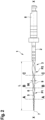
- the dental root canal instrument 1 As from Fig.2 As can be seen, the dental root canal instrument 1 according to the first embodiment comprises a shaft region 2, a cutting region 3 and a connecting piece 8.
- the connecting piece 8 serves for connection to a drive or a handpiece with which a dentist can operate the root canal instrument.
- the cutting area 3 provided with cutting edges runs from a tip 7 of the root canal instrument to the shaft area 2.
- the cutting area 3 has a total length L in the axial direction X-X of the root canal instrument.
- the cutting area 3 has exactly two cutting edges 5, 6, which wind in a spiral shape in the longitudinal direction of the root canal instrument. This creates chip grooves 9 between the two cutting edges 5, 6, which continuously expand from the tip 7 in the direction of the shaft area 2 in terms of both a width 90 and a depth T. This ensures that removed material is safely removed from the root canal.
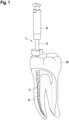
- Fig.1 shows schematically the use of the root canal instrument 1 in a tooth 10, which is shown as a molar.
- a root canal 11 of the tooth 10 is curved. Since the root canals are individually very different, the root canal instrument 1 must have very good flexibility, as shown schematically in Fig.1 shown.
- the cutting area 3 also has a core 4 (solid material core) that runs from the tip 7 to the shaft area 2.
- the core 4 widens conically from the tip 7 of the root canal instrument to the shaft area 2.
- An envelope curve H of the two cutting edges 5, 6 also widens conically from the tip of the root canal instrument to the shaft area 2.
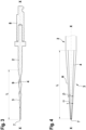
- the envelope curve H of the cutting edges expands with a first slope with a first angle a, which is larger than a second slope with a second angle ⁇ of the core 4. This can be seen in detail from Fig.4 visible.
- the envelope curves H of the cutting edges and the core 4 no longer run parallel and with the same gradient as in the prior art, but the gradient of the core 4 is smaller than that of the envelope curve H of the cutting edges.
- the flexibility of the root canal instrument in the shaft area 3 can thus be significantly increased in comparison with the state of the art.
- the cross sections of the core 4 and the cutting area 3 are shown schematically in the Fig. 2a to 2c
- the core 4 at section AA of Fig. 2a a first diameter D1.
- This first diameter D1 is smaller than a second diameter D2 at the intersection point BB of Fig. 2b .
- the second diameter D2 is smaller than a third diameter D3 at the intersection point CC of Fig. 2c .
- a diameter of the outer envelope curve H of the cutting edges with the larger first pitch increases significantly faster in the direction of the shaft area 2 than the diameter of the core 4.
- the two cones of the core 4 and the envelope curve H of the cutting edges form two cylindrical cones with the same height, which, however, have base areas of different sizes at the transition to the shaft area 2, since the pitch of the two straight circular cones is different.
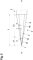
- Fig.5 shows schematically the structure of a root canal instrument according to a second example for explaining the present invention. Identical or functionally identical parts are designated with the same reference numerals.
- the second example corresponds essentially to the first example, whereby in contrast to the first example, the soul 4 in the second example is designed differently.
- the core 4 has a first conical region 41 which begins at the tip 7 and extends to a first point P1.
- the first conical area 41 is followed by a second conical area 42 of the core, which extends to the shaft area 2. As in Fig.5 As shown, a slope of the first and second conical region 41, 42 is different. The second angle ⁇ at the first conical region 41 is greater than a third angle ⁇ at the second conical region 42.
- the envelope curve H of the cutting edges 5, 6 runs conically continuously from the tip 7 to the shaft region 2 with the first angle a, as in the first embodiment. Thus, ⁇ > ⁇ > ⁇ .
- the flexibility of the dental instrument 1 can be varied over the total length L.
- the first conical region 41 runs over a length L1 in the axial direction XX of the root canal instrument and the second conical region 42 runs over a length L2.
- the length L2 is significantly greater than the length L1.
- the slightly larger slope with the second angle ⁇ on the first conical region 41 makes it possible in particular to avoid the dental instrument having a core that is too small and with too small a diameter in the area of the tip, which could lead to a risk of the dental instrument breaking in this area. This can be avoided by choosing the slope with the second angle ⁇ .
- the core of the second embodiment is thus composed of a truncated cone and a cone, with an edge-free transition between the cone and the truncated cone preferably being provided.
- further truncated cones with other jacket angles could be arranged.
- this embodiment corresponds to the previous embodiment, so that reference can be made to the description given there.
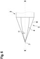
- Fig.6 shows a schematic view of a root canal instrument according to a third example, which, however, does not fall under the claims, to explain the present invention. Identical or functionally identical parts are again designated with the same reference numerals.
- the core in the third example which does not fall under the claims, has the shape of a paraboloid for explanation purposes.
- the envelope curve of the core 4 is thereby defined by a parabola rotated around the central axis.
- the slope of the core 4 thus decreases continuously from the tip 7 in the direction of the shaft region 2, but remains positive. It would also be possible for the paraboloid to change into a cylinder in the direction of the shaft region 2. This makes it possible to obtain a very flexible root canal instrument. Otherwise, this embodiment corresponds to the previous embodiments, so that reference can be made to the description given there.
Landscapes
- Health & Medical Sciences (AREA)
- Engineering & Computer Science (AREA)
- Biomedical Technology (AREA)
- Neurology (AREA)
- Neurosurgery (AREA)
- Nuclear Medicine, Radiotherapy & Molecular Imaging (AREA)
- Surgery (AREA)
- Oral & Maxillofacial Surgery (AREA)
- Dentistry (AREA)
- Epidemiology (AREA)
- Life Sciences & Earth Sciences (AREA)
- Animal Behavior & Ethology (AREA)
- General Health & Medical Sciences (AREA)
- Public Health (AREA)
- Veterinary Medicine (AREA)
- Dental Tools And Instruments Or Auxiliary Dental Instruments (AREA)
Priority Applications (1)
| Application Number | Priority Date | Filing Date | Title |
|---|---|---|---|
| PL20152244.8T PL3682841T5 (pl) | 2019-01-17 | 2020-01-16 | Dentystyczne narzędzie do kanału korzenia |
Applications Claiming Priority (1)
| Application Number | Priority Date | Filing Date | Title |
|---|---|---|---|
| DE102019101174.4A DE102019101174A1 (de) | 2019-01-17 | 2019-01-17 | Dentales Wurzelkanalinstrument |
Publications (3)
| Publication Number | Publication Date |
|---|---|
| EP3682841A1 EP3682841A1 (de) | 2020-07-22 |
| EP3682841B1 EP3682841B1 (de) | 2021-10-13 |
| EP3682841B2 true EP3682841B2 (de) | 2024-09-11 |
Family
ID=69174421
Family Applications (1)
| Application Number | Title | Priority Date | Filing Date |
|---|---|---|---|
| EP20152244.8A Active EP3682841B2 (de) | 2019-01-17 | 2020-01-16 | Dentales wurzelkanalinstrument |
Country Status (5)
| Country | Link |
|---|---|
| US (1) | US12357425B2 (pl) |
| EP (1) | EP3682841B2 (pl) |
| DE (1) | DE102019101174A1 (pl) |
| ES (1) | ES2902429T5 (pl) |
| PL (1) | PL3682841T5 (pl) |
Families Citing this family (1)
| Publication number | Priority date | Publication date | Assignee | Title |
|---|---|---|---|---|
| US11628042B1 (en) * | 2022-03-07 | 2023-04-18 | William B. Johnson | Endodontic instrument with enlarged chip space and reduced torque strength |
Family Cites Families (35)
| Publication number | Priority date | Publication date | Assignee | Title |
|---|---|---|---|---|
| US4332561A (en) * | 1979-08-03 | 1982-06-01 | Inventive Technology International, Inc. | Dental file |
| US4538989A (en) * | 1979-10-01 | 1985-09-03 | Dentsply International, Inc. | Dental reamer |
| FR2587197A1 (fr) * | 1985-09-13 | 1987-03-20 | Reynaud Marc | Tenon d'ancrage d'une prothese dentaire dans la racine d'une dent |
| US4934934A (en) * | 1988-11-04 | 1990-06-19 | Quality Dental Products, Inc. | Dental file/reamer instrument |
| US5106298A (en) * | 1991-04-03 | 1992-04-21 | Heath Derek E | Endodontic dental instrument |
| US6206695B1 (en) * | 1994-02-14 | 2001-03-27 | Nelson J. Wong | Step-back eliminating tapered dental cutting instruments for improved root canal treatment and method |
| US5653590A (en) * | 1995-06-06 | 1997-08-05 | Tulsa Dental Products, L.L.C. | Kit of endodontic instruments and method of utilizing same |
| US5713736A (en) * | 1996-05-01 | 1998-02-03 | Tulsa Dental Products, L.L.C. | Endodontic dental instrument |
| US5882198A (en) * | 1997-03-28 | 1999-03-16 | Ormco Corporation | Endodontic instrument having enhanced compliance at the tip |
| US5857852A (en) * | 1997-11-19 | 1999-01-12 | The Kerr Corporation | Endodontic file with non-helical flutes |
| AU2877499A (en) | 1998-02-26 | 1999-09-15 | Ormco Corporation | Multi-pass grinding method |
| WO2000028915A1 (de) * | 1998-11-17 | 2000-05-25 | Gebr. Brasseler Gmbh & Co. Kg | Wurzelkanalinstrument und verfahren zu dessen herstellung |
| US6293794B1 (en) * | 1999-02-16 | 2001-09-25 | Ormco Corporation | Endodontic instrument having regressive conicity |
| US6299445B1 (en) * | 1999-04-08 | 2001-10-09 | Ormco Corporation | Endodontic instrument, instrument blank and method of manufacture |
| US6409506B1 (en) * | 2000-05-01 | 2002-06-25 | Miltex Dental, Inc. | Endodontic instruments and process for producing the same |
| US6712611B2 (en) * | 2001-10-05 | 2004-03-30 | Ormco Corporation | Endodontic instrument with controlled flexibility and method of manufacturing same |
| US6783438B2 (en) | 2002-04-18 | 2004-08-31 | Ormco Corporation | Method of manufacturing an endodontic instrument |
| US7147469B2 (en) * | 2002-08-28 | 2006-12-12 | Ormco Corporation | Endodontic instrument |
| US20060228667A1 (en) * | 2005-04-12 | 2006-10-12 | Buchanan L Stephen | Endodontic instruments with pilot tips and parabolic cutting flutes |
| US7311522B2 (en) * | 2003-03-31 | 2007-12-25 | Miltex Technology Corporation | Endodontic instruments and method of manufacturing same |
| US6981869B2 (en) * | 2003-04-22 | 2006-01-03 | Ruddle Clifford J | Injection molded endodontic brush |
| US7955078B2 (en) * | 2003-05-01 | 2011-06-07 | Scianamblo Michael J | Endodontic instruments for preparing endodontic cavity spaces |
| US20050214711A1 (en) * | 2003-10-20 | 2005-09-29 | Buchanan L S | Endodontic instruments with pilot tips and parabolic cutting flutes |
| US7967605B2 (en) * | 2004-03-16 | 2011-06-28 | Guidance Endodontics, Llc | Endodontic files and obturator devices and methods of manufacturing same |
| US20060127843A1 (en) * | 2004-12-15 | 2006-06-15 | Discus Dental Impressions, Inc. | Endodontic instruments |
| ATE503433T1 (de) * | 2005-04-08 | 2011-04-15 | Michael J Scianamblo | Sich biegende endodontische instrumente |
| FR2886837B1 (fr) * | 2005-06-14 | 2008-04-11 | Micro Mega Int Mfg Sa | Ebauche pour la fabrication d'un instrument endodontique et procede pour la fabrication dudit instrument |
| US7766657B2 (en) * | 2005-08-09 | 2010-08-03 | Andris Jaunberzins | Endodontic file combining active and passive cutting edges |
| US7270541B1 (en) * | 2006-03-02 | 2007-09-18 | Johnson William B | Endodontic files having variable helical angle flutes |
| IL216587A (en) | 2011-11-24 | 2014-09-30 | Medic Nrg Ltd | Endodontic cutter with outer spiral thread |
| WO2013114154A1 (en) * | 2012-01-30 | 2013-08-08 | Sweden & Martina Spa | Reamer with an improved blade for root canal preparation |
| DE202012012526U1 (de) | 2012-06-29 | 2013-03-15 | Gebr. Brasseler Gmbh & Co. Kg | Wurzelkanalinstrument |
| US20140272802A1 (en) * | 2013-02-21 | 2014-09-18 | Nathan Y. LI | Multi-taper dental root canal filling points/cones and process of making same |
| JP6845308B2 (ja) * | 2016-08-19 | 2021-03-17 | リー,ネイサン,ワイ. | キャリアベースの歯根管オブチュレータ |
| DE202019100258U1 (de) | 2019-01-17 | 2019-01-25 | Gebr. Brasseler Gmbh & Co. Kg | Dentales Wurzelkanalinstrument |
-
2019
- 2019-01-17 DE DE102019101174.4A patent/DE102019101174A1/de active Pending
-
2020
- 2020-01-14 US US16/742,284 patent/US12357425B2/en active Active
- 2020-01-16 EP EP20152244.8A patent/EP3682841B2/de active Active
- 2020-01-16 ES ES20152244T patent/ES2902429T5/es active Active
- 2020-01-16 PL PL20152244.8T patent/PL3682841T5/pl unknown
Also Published As
| Publication number | Publication date |
|---|---|
| EP3682841A1 (de) | 2020-07-22 |
| US12357425B2 (en) | 2025-07-15 |
| EP3682841B1 (de) | 2021-10-13 |
| PL3682841T3 (pl) | 2022-02-14 |
| ES2902429T5 (en) | 2025-02-07 |
| ES2902429T3 (es) | 2022-03-28 |
| DE102019101174A1 (de) | 2020-07-23 |
| PL3682841T5 (pl) | 2024-12-02 |
| US20200229899A1 (en) | 2020-07-23 |
Similar Documents
| Publication | Publication Date | Title |
|---|---|---|
| EP0674880B1 (de) | Schraube aus bioabbaubarem Material für osteochirurgische Zwecke, sowie dazu passender Schraubendreher | |
| DE60010634T2 (de) | Hochflexibles Instrument für medizinische und/oder zahnärztliche Anwendungen | |
| DE68923787T2 (de) | Zahnanker mit gewinde. | |
| EP1204382B1 (de) | Knochenschraube | |
| DE69621464T2 (de) | Endodontisches instrument | |
| DE602004006029T2 (de) | Marknagel | |
| EP0421457A1 (de) | Vorrichtung zur Entfernung von Ablagerungen in GefÀ¤ssen | |
| EP1246578A2 (de) | Knochenschraube | |
| EP3021782B1 (de) | Zahnimplantat mit koronaler nutstruktur | |
| EP1391186A1 (de) | Verfahren zum Herstellen eines rohrförmigen Platzhalters, und Platzhalter | |
| EP0186656A1 (de) | Verriegelungsnagel | |
| WO1999022807A1 (de) | Vorrichtung zum herausziehen eines ein längliches innenlumen aufweisenden gegenstandes aus seiner verankerung in einem körper | |
| DE2628443C2 (de) | Stiftförmiges Knochenimplantat aus Keramik | |
| EP3682841B2 (de) | Dentales wurzelkanalinstrument | |
| EP0713017A2 (de) | Selbstschneidende Schraube | |
| DE202019100258U1 (de) | Dentales Wurzelkanalinstrument | |
| DE29908794U1 (de) | Kanüle, insbesondere zum Einführen in den Spinalkanal | |
| EP1279378A2 (de) | Wurzelkanalinstrumentenset | |
| EP0330173A1 (de) | Zahnwurzelbearbeitungsinstrument | |
| EP1792579A1 (de) | Wurzelkanalinstrument | |
| EP3410955B1 (de) | Medizinisches gerät | |
| DE10135820C1 (de) | Wurzelkanalinstrumentenset mit balligen Arbeitsteilen | |
| EP4285861B1 (de) | Dentalimplantat | |
| DE10135821C1 (de) | Wurzelkanalinstrumentenset mit konischen Arbeitsteilen | |
| EP2801330A1 (de) | Knochenplatte mit einem Inlay und Verfahren zum Herstellen einer Knochenplatte |
Legal Events
| Date | Code | Title | Description |
|---|---|---|---|
| PUAI | Public reference made under article 153(3) epc to a published international application that has entered the european phase |
Free format text: ORIGINAL CODE: 0009012 |
|
| STAA | Information on the status of an ep patent application or granted ep patent |
Free format text: STATUS: THE APPLICATION HAS BEEN PUBLISHED |
|
| AK | Designated contracting states |
Kind code of ref document: A1 Designated state(s): AL AT BE BG CH CY CZ DE DK EE ES FI FR GB GR HR HU IE IS IT LI LT LU LV MC MK MT NL NO PL PT RO RS SE SI SK SM TR |
|
| AX | Request for extension of the european patent |
Extension state: BA ME |
|
| STAA | Information on the status of an ep patent application or granted ep patent |
Free format text: STATUS: REQUEST FOR EXAMINATION WAS MADE |
|
| 17P | Request for examination filed |
Effective date: 20201210 |
|
| RBV | Designated contracting states (corrected) |
Designated state(s): AL AT BE BG CH CY CZ DE DK EE ES FI FR GB GR HR HU IE IS IT LI LT LU LV MC MK MT NL NO PL PT RO RS SE SI SK SM TR |
|
| GRAP | Despatch of communication of intention to grant a patent |
Free format text: ORIGINAL CODE: EPIDOSNIGR1 |
|
| STAA | Information on the status of an ep patent application or granted ep patent |
Free format text: STATUS: GRANT OF PATENT IS INTENDED |
|
| INTG | Intention to grant announced |
Effective date: 20210510 |
|
| GRAS | Grant fee paid |
Free format text: ORIGINAL CODE: EPIDOSNIGR3 |
|
| GRAA | (expected) grant |
Free format text: ORIGINAL CODE: 0009210 |
|
| STAA | Information on the status of an ep patent application or granted ep patent |
Free format text: STATUS: THE PATENT HAS BEEN GRANTED |
|
| AK | Designated contracting states |
Kind code of ref document: B1 Designated state(s): AL AT BE BG CH CY CZ DE DK EE ES FI FR GB GR HR HU IE IS IT LI LT LU LV MC MK MT NL NO PL PT RO RS SE SI SK SM TR |
|
| REG | Reference to a national code |
Ref country code: GB Ref legal event code: FG4D Free format text: NOT ENGLISH |
|
| REG | Reference to a national code |
Ref country code: CH Ref legal event code: EP |
|
| REG | Reference to a national code |
Ref country code: DE Ref legal event code: R096 Ref document number: 502020000252 Country of ref document: DE |
|
| REG | Reference to a national code |
Ref country code: IE Ref legal event code: FG4D Free format text: LANGUAGE OF EP DOCUMENT: GERMAN |
|
| REG | Reference to a national code |
Ref country code: AT Ref legal event code: REF Ref document number: 1437560 Country of ref document: AT Kind code of ref document: T Effective date: 20211115 |
|
| REG | Reference to a national code |
Ref country code: NL Ref legal event code: FP |
|
| REG | Reference to a national code |
Ref country code: LT Ref legal event code: MG9D |
|
| REG | Reference to a national code |
Ref country code: ES Ref legal event code: FG2A Ref document number: 2902429 Country of ref document: ES Kind code of ref document: T3 Effective date: 20220328 |
|
| PG25 | Lapsed in a contracting state [announced via postgrant information from national office to epo] |
Ref country code: RS Free format text: LAPSE BECAUSE OF FAILURE TO SUBMIT A TRANSLATION OF THE DESCRIPTION OR TO PAY THE FEE WITHIN THE PRESCRIBED TIME-LIMIT Effective date: 20211013 Ref country code: LT Free format text: LAPSE BECAUSE OF FAILURE TO SUBMIT A TRANSLATION OF THE DESCRIPTION OR TO PAY THE FEE WITHIN THE PRESCRIBED TIME-LIMIT Effective date: 20211013 Ref country code: FI Free format text: LAPSE BECAUSE OF FAILURE TO SUBMIT A TRANSLATION OF THE DESCRIPTION OR TO PAY THE FEE WITHIN THE PRESCRIBED TIME-LIMIT Effective date: 20211013 Ref country code: BG Free format text: LAPSE BECAUSE OF FAILURE TO SUBMIT A TRANSLATION OF THE DESCRIPTION OR TO PAY THE FEE WITHIN THE PRESCRIBED TIME-LIMIT Effective date: 20220113 |
|
| PG25 | Lapsed in a contracting state [announced via postgrant information from national office to epo] |
Ref country code: IS Free format text: LAPSE BECAUSE OF FAILURE TO SUBMIT A TRANSLATION OF THE DESCRIPTION OR TO PAY THE FEE WITHIN THE PRESCRIBED TIME-LIMIT Effective date: 20220213 Ref country code: SE Free format text: LAPSE BECAUSE OF FAILURE TO SUBMIT A TRANSLATION OF THE DESCRIPTION OR TO PAY THE FEE WITHIN THE PRESCRIBED TIME-LIMIT Effective date: 20211013 Ref country code: PT Free format text: LAPSE BECAUSE OF FAILURE TO SUBMIT A TRANSLATION OF THE DESCRIPTION OR TO PAY THE FEE WITHIN THE PRESCRIBED TIME-LIMIT Effective date: 20220214 Ref country code: NO Free format text: LAPSE BECAUSE OF FAILURE TO SUBMIT A TRANSLATION OF THE DESCRIPTION OR TO PAY THE FEE WITHIN THE PRESCRIBED TIME-LIMIT Effective date: 20220113 Ref country code: LV Free format text: LAPSE BECAUSE OF FAILURE TO SUBMIT A TRANSLATION OF THE DESCRIPTION OR TO PAY THE FEE WITHIN THE PRESCRIBED TIME-LIMIT Effective date: 20211013 Ref country code: HR Free format text: LAPSE BECAUSE OF FAILURE TO SUBMIT A TRANSLATION OF THE DESCRIPTION OR TO PAY THE FEE WITHIN THE PRESCRIBED TIME-LIMIT Effective date: 20211013 Ref country code: GR Free format text: LAPSE BECAUSE OF FAILURE TO SUBMIT A TRANSLATION OF THE DESCRIPTION OR TO PAY THE FEE WITHIN THE PRESCRIBED TIME-LIMIT Effective date: 20220114 |
|
| REG | Reference to a national code |
Ref country code: DE Ref legal event code: R026 Ref document number: 502020000252 Country of ref document: DE |
|
| PLBI | Opposition filed |
Free format text: ORIGINAL CODE: 0009260 |
|
| PLAX | Notice of opposition and request to file observation + time limit sent |
Free format text: ORIGINAL CODE: EPIDOSNOBS2 |
|
| PG25 | Lapsed in a contracting state [announced via postgrant information from national office to epo] |
Ref country code: SM Free format text: LAPSE BECAUSE OF FAILURE TO SUBMIT A TRANSLATION OF THE DESCRIPTION OR TO PAY THE FEE WITHIN THE PRESCRIBED TIME-LIMIT Effective date: 20211013 Ref country code: SK Free format text: LAPSE BECAUSE OF FAILURE TO SUBMIT A TRANSLATION OF THE DESCRIPTION OR TO PAY THE FEE WITHIN THE PRESCRIBED TIME-LIMIT Effective date: 20211013 Ref country code: RO Free format text: LAPSE BECAUSE OF FAILURE TO SUBMIT A TRANSLATION OF THE DESCRIPTION OR TO PAY THE FEE WITHIN THE PRESCRIBED TIME-LIMIT Effective date: 20211013 Ref country code: EE Free format text: LAPSE BECAUSE OF FAILURE TO SUBMIT A TRANSLATION OF THE DESCRIPTION OR TO PAY THE FEE WITHIN THE PRESCRIBED TIME-LIMIT Effective date: 20211013 Ref country code: DK Free format text: LAPSE BECAUSE OF FAILURE TO SUBMIT A TRANSLATION OF THE DESCRIPTION OR TO PAY THE FEE WITHIN THE PRESCRIBED TIME-LIMIT Effective date: 20211013 Ref country code: CZ Free format text: LAPSE BECAUSE OF FAILURE TO SUBMIT A TRANSLATION OF THE DESCRIPTION OR TO PAY THE FEE WITHIN THE PRESCRIBED TIME-LIMIT Effective date: 20211013 |
|
| 26 | Opposition filed |
Opponent name: DENTSPLY SIRONA INC. Effective date: 20220712 |
|
| PG25 | Lapsed in a contracting state [announced via postgrant information from national office to epo] |
Ref country code: MC Free format text: LAPSE BECAUSE OF FAILURE TO SUBMIT A TRANSLATION OF THE DESCRIPTION OR TO PAY THE FEE WITHIN THE PRESCRIBED TIME-LIMIT Effective date: 20211013 |
|
| PG25 | Lapsed in a contracting state [announced via postgrant information from national office to epo] |
Ref country code: LU Free format text: LAPSE BECAUSE OF NON-PAYMENT OF DUE FEES Effective date: 20220116 Ref country code: AL Free format text: LAPSE BECAUSE OF FAILURE TO SUBMIT A TRANSLATION OF THE DESCRIPTION OR TO PAY THE FEE WITHIN THE PRESCRIBED TIME-LIMIT Effective date: 20211013 |
|
| PG25 | Lapsed in a contracting state [announced via postgrant information from national office to epo] |
Ref country code: SI Free format text: LAPSE BECAUSE OF FAILURE TO SUBMIT A TRANSLATION OF THE DESCRIPTION OR TO PAY THE FEE WITHIN THE PRESCRIBED TIME-LIMIT Effective date: 20211013 |
|
| PLBB | Reply of patent proprietor to notice(s) of opposition received |
Free format text: ORIGINAL CODE: EPIDOSNOBS3 |
|
| PG25 | Lapsed in a contracting state [announced via postgrant information from national office to epo] |
Ref country code: IE Free format text: LAPSE BECAUSE OF NON-PAYMENT OF DUE FEES Effective date: 20220116 |
|
| P01 | Opt-out of the competence of the unified patent court (upc) registered |
Effective date: 20230427 |
|
| REG | Reference to a national code |
Ref country code: CH Ref legal event code: PL |
|
| PG25 | Lapsed in a contracting state [announced via postgrant information from national office to epo] |
Ref country code: LI Free format text: LAPSE BECAUSE OF NON-PAYMENT OF DUE FEES Effective date: 20230131 Ref country code: CH Free format text: LAPSE BECAUSE OF NON-PAYMENT OF DUE FEES Effective date: 20230131 |
|
| PLBP | Opposition withdrawn |
Free format text: ORIGINAL CODE: 0009264 |
|
| PG25 | Lapsed in a contracting state [announced via postgrant information from national office to epo] |
Ref country code: MK Free format text: LAPSE BECAUSE OF FAILURE TO SUBMIT A TRANSLATION OF THE DESCRIPTION OR TO PAY THE FEE WITHIN THE PRESCRIBED TIME-LIMIT Effective date: 20211013 Ref country code: CY Free format text: LAPSE BECAUSE OF FAILURE TO SUBMIT A TRANSLATION OF THE DESCRIPTION OR TO PAY THE FEE WITHIN THE PRESCRIBED TIME-LIMIT Effective date: 20211013 |
|
| PG25 | Lapsed in a contracting state [announced via postgrant information from national office to epo] |
Ref country code: HU Free format text: LAPSE BECAUSE OF FAILURE TO SUBMIT A TRANSLATION OF THE DESCRIPTION OR TO PAY THE FEE WITHIN THE PRESCRIBED TIME-LIMIT; INVALID AB INITIO Effective date: 20200116 |
|
| PUAH | Patent maintained in amended form |
Free format text: ORIGINAL CODE: 0009272 |
|
| STAA | Information on the status of an ep patent application or granted ep patent |
Free format text: STATUS: PATENT MAINTAINED AS AMENDED |
|
| 27A | Patent maintained in amended form |
Effective date: 20240911 |
|
| AK | Designated contracting states |
Kind code of ref document: B2 Designated state(s): AL AT BE BG CH CY CZ DE DK EE ES FI FR GB GR HR HU IE IS IT LI LT LU LV MC MK MT NL NO PL PT RO RS SE SI SK SM TR |
|
| REG | Reference to a national code |
Ref country code: DE Ref legal event code: R102 Ref document number: 502020000252 Country of ref document: DE |
|
| GBPC | Gb: european patent ceased through non-payment of renewal fee |
Effective date: 20240116 |
|
| PG25 | Lapsed in a contracting state [announced via postgrant information from national office to epo] |
Ref country code: MT Free format text: LAPSE BECAUSE OF FAILURE TO SUBMIT A TRANSLATION OF THE DESCRIPTION OR TO PAY THE FEE WITHIN THE PRESCRIBED TIME-LIMIT Effective date: 20211013 |
|
| PG25 | Lapsed in a contracting state [announced via postgrant information from national office to epo] |
Ref country code: GB Free format text: LAPSE BECAUSE OF NON-PAYMENT OF DUE FEES Effective date: 20240116 |
|
| PG25 | Lapsed in a contracting state [announced via postgrant information from national office to epo] |
Ref country code: GB Free format text: LAPSE BECAUSE OF NON-PAYMENT OF DUE FEES Effective date: 20240116 |
|
| REG | Reference to a national code |
Ref country code: NL Ref legal event code: FP |
|
| REG | Reference to a national code |
Ref country code: ES Ref legal event code: DC2A Ref document number: 2902429 Country of ref document: ES Kind code of ref document: T5 Effective date: 20250207 |
|
| PGFP | Annual fee paid to national office [announced via postgrant information from national office to epo] |
Ref country code: PL Payment date: 20250108 Year of fee payment: 6 |
|
| PG25 | Lapsed in a contracting state [announced via postgrant information from national office to epo] |
Ref country code: TR Free format text: LAPSE BECAUSE OF FAILURE TO SUBMIT A TRANSLATION OF THE DESCRIPTION OR TO PAY THE FEE WITHIN THE PRESCRIBED TIME-LIMIT Effective date: 20211013 |
|
| PGFP | Annual fee paid to national office [announced via postgrant information from national office to epo] |
Ref country code: NL Payment date: 20260121 Year of fee payment: 7 |
|
| PGFP | Annual fee paid to national office [announced via postgrant information from national office to epo] |
Ref country code: ES Payment date: 20260217 Year of fee payment: 7 |
|
| PGFP | Annual fee paid to national office [announced via postgrant information from national office to epo] |
Ref country code: DE Payment date: 20260128 Year of fee payment: 7 |
|
| PGFP | Annual fee paid to national office [announced via postgrant information from national office to epo] |
Ref country code: AT Payment date: 20260119 Year of fee payment: 7 |
|
| PGFP | Annual fee paid to national office [announced via postgrant information from national office to epo] |
Ref country code: BE Payment date: 20260121 Year of fee payment: 7 Ref country code: IT Payment date: 20260130 Year of fee payment: 7 |
|
| PGFP | Annual fee paid to national office [announced via postgrant information from national office to epo] |
Ref country code: FR Payment date: 20260121 Year of fee payment: 7 |