EP3681816B1 - A receptacle for aerosol-generating articles - Google Patents
A receptacle for aerosol-generating articles Download PDFInfo
- Publication number
- EP3681816B1 EP3681816B1 EP18765919.8A EP18765919A EP3681816B1 EP 3681816 B1 EP3681816 B1 EP 3681816B1 EP 18765919 A EP18765919 A EP 18765919A EP 3681816 B1 EP3681816 B1 EP 3681816B1
- Authority
- EP
- European Patent Office
- Prior art keywords
- box
- container
- receptacle
- clip
- box portion
- Prior art date
- Legal status (The legal status is an assumption and is not a legal conclusion. Google has not performed a legal analysis and makes no representation as to the accuracy of the status listed.)
- Active
Links
Images


Classifications
-
- A—HUMAN NECESSITIES
- A24—TOBACCO; CIGARS; CIGARETTES; SIMULATED SMOKING DEVICES; SMOKERS' REQUISITES
- A24F—SMOKERS' REQUISITES; MATCH BOXES; SIMULATED SMOKING DEVICES
- A24F15/00—Receptacles or boxes specially adapted for cigars, cigarettes, simulated smoking devices or cigarettes therefor
- A24F15/01—Receptacles or boxes specially adapted for cigars, cigarettes, simulated smoking devices or cigarettes therefor specially adapted for simulated smoking devices or cigarettes therefor
-
- B—PERFORMING OPERATIONS; TRANSPORTING
- B65—CONVEYING; PACKING; STORING; HANDLING THIN OR FILAMENTARY MATERIAL
- B65D—CONTAINERS FOR STORAGE OR TRANSPORT OF ARTICLES OR MATERIALS, e.g. BAGS, BARRELS, BOTTLES, BOXES, CANS, CARTONS, CRATES, DRUMS, JARS, TANKS, HOPPERS, FORWARDING CONTAINERS; ACCESSORIES, CLOSURES, OR FITTINGS THEREFOR; PACKAGING ELEMENTS; PACKAGES
- B65D67/00—Kinds or types of packaging elements not otherwise provided for
- B65D67/02—Clips or clamps for holding articles together for convenience of storage or transport
-
- A—HUMAN NECESSITIES
- A24—TOBACCO; CIGARS; CIGARETTES; SIMULATED SMOKING DEVICES; SMOKERS' REQUISITES
- A24F—SMOKERS' REQUISITES; MATCH BOXES; SIMULATED SMOKING DEVICES
- A24F15/00—Receptacles or boxes specially adapted for cigars, cigarettes, simulated smoking devices or cigarettes therefor
- A24F15/12—Receptacles or boxes specially adapted for cigars, cigarettes, simulated smoking devices or cigarettes therefor for pocket use
- A24F15/18—Receptacles or boxes specially adapted for cigars, cigarettes, simulated smoking devices or cigarettes therefor for pocket use combined with other objects
-
- A—HUMAN NECESSITIES
- A24—TOBACCO; CIGARS; CIGARETTES; SIMULATED SMOKING DEVICES; SMOKERS' REQUISITES
- A24F—SMOKERS' REQUISITES; MATCH BOXES; SIMULATED SMOKING DEVICES
- A24F19/00—Ash-trays
- A24F19/0064—Ash-trays of the pocket type
-
- B—PERFORMING OPERATIONS; TRANSPORTING
- B65—CONVEYING; PACKING; STORING; HANDLING THIN OR FILAMENTARY MATERIAL
- B65D—CONTAINERS FOR STORAGE OR TRANSPORT OF ARTICLES OR MATERIALS, e.g. BAGS, BARRELS, BOTTLES, BOXES, CANS, CARTONS, CRATES, DRUMS, JARS, TANKS, HOPPERS, FORWARDING CONTAINERS; ACCESSORIES, CLOSURES, OR FITTINGS THEREFOR; PACKAGING ELEMENTS; PACKAGES
- B65D21/00—Nestable, stackable or joinable containers; Containers of variable capacity
- B65D21/02—Containers specially shaped, or provided with fittings or attachments, to facilitate nesting, stacking, or joining together
- B65D21/0201—Containers specially shaped, or provided with fittings or attachments, to facilitate nesting, stacking, or joining together stackable or joined together side-by-side
-
- B—PERFORMING OPERATIONS; TRANSPORTING
- B65—CONVEYING; PACKING; STORING; HANDLING THIN OR FILAMENTARY MATERIAL
- B65D—CONTAINERS FOR STORAGE OR TRANSPORT OF ARTICLES OR MATERIALS, e.g. BAGS, BARRELS, BOTTLES, BOXES, CANS, CARTONS, CRATES, DRUMS, JARS, TANKS, HOPPERS, FORWARDING CONTAINERS; ACCESSORIES, CLOSURES, OR FITTINGS THEREFOR; PACKAGING ELEMENTS; PACKAGES
- B65D21/00—Nestable, stackable or joinable containers; Containers of variable capacity
- B65D21/02—Containers specially shaped, or provided with fittings or attachments, to facilitate nesting, stacking, or joining together
- B65D21/0209—Containers specially shaped, or provided with fittings or attachments, to facilitate nesting, stacking, or joining together stackable or joined together one-upon-the-other in the upright or upside-down position
- B65D21/023—Closed containers provided with local cooperating elements in the top and bottom surfaces, e.g. projection and recess
-
- B—PERFORMING OPERATIONS; TRANSPORTING
- B65—CONVEYING; PACKING; STORING; HANDLING THIN OR FILAMENTARY MATERIAL
- B65D—CONTAINERS FOR STORAGE OR TRANSPORT OF ARTICLES OR MATERIALS, e.g. BAGS, BARRELS, BOTTLES, BOXES, CANS, CARTONS, CRATES, DRUMS, JARS, TANKS, HOPPERS, FORWARDING CONTAINERS; ACCESSORIES, CLOSURES, OR FITTINGS THEREFOR; PACKAGING ELEMENTS; PACKAGES
- B65D5/00—Rigid or semi-rigid containers of polygonal cross-section, e.g. boxes, cartons or trays, formed by folding or erecting one or more blanks made of paper
- B65D5/42—Details of containers or of foldable or erectable container blanks
- B65D5/427—Individual packages joined together, e.g. by means of integral tabs
-
- B—PERFORMING OPERATIONS; TRANSPORTING
- B65—CONVEYING; PACKING; STORING; HANDLING THIN OR FILAMENTARY MATERIAL
- B65D—CONTAINERS FOR STORAGE OR TRANSPORT OF ARTICLES OR MATERIALS, e.g. BAGS, BARRELS, BOTTLES, BOXES, CANS, CARTONS, CRATES, DRUMS, JARS, TANKS, HOPPERS, FORWARDING CONTAINERS; ACCESSORIES, CLOSURES, OR FITTINGS THEREFOR; PACKAGING ELEMENTS; PACKAGES
- B65D69/00—Articles joined together for convenience of storage or transport without the use of packaging elements
-
- B—PERFORMING OPERATIONS; TRANSPORTING
- B65—CONVEYING; PACKING; STORING; HANDLING THIN OR FILAMENTARY MATERIAL
- B65D—CONTAINERS FOR STORAGE OR TRANSPORT OF ARTICLES OR MATERIALS, e.g. BAGS, BARRELS, BOTTLES, BOXES, CANS, CARTONS, CRATES, DRUMS, JARS, TANKS, HOPPERS, FORWARDING CONTAINERS; ACCESSORIES, CLOSURES, OR FITTINGS THEREFOR; PACKAGING ELEMENTS; PACKAGES
- B65D85/00—Containers, packaging elements or packages, specially adapted for particular articles or materials
- B65D85/07—Containers, packaging elements or packages, specially adapted for particular articles or materials for compressible or flexible articles
- B65D85/08—Containers, packaging elements or packages, specially adapted for particular articles or materials for compressible or flexible articles rod-shaped or tubular
- B65D85/10—Containers, packaging elements or packages, specially adapted for particular articles or materials for compressible or flexible articles rod-shaped or tubular for cigarettes
- B65D85/1036—Containers formed by erecting a rigid or semi-rigid blank
- B65D85/1045—Containers formed by erecting a rigid or semi-rigid blank having a cap-like lid hinged to an edge
- B65D85/1048—Containers formed by erecting a rigid or semi-rigid blank having a cap-like lid hinged to an edge characterized by the shape of the container
- B65D85/10484—Containers formed by erecting a rigid or semi-rigid blank having a cap-like lid hinged to an edge characterized by the shape of the container having rounded corners
-
- B—PERFORMING OPERATIONS; TRANSPORTING
- B65—CONVEYING; PACKING; STORING; HANDLING THIN OR FILAMENTARY MATERIAL
- B65D—CONTAINERS FOR STORAGE OR TRANSPORT OF ARTICLES OR MATERIALS, e.g. BAGS, BARRELS, BOTTLES, BOXES, CANS, CARTONS, CRATES, DRUMS, JARS, TANKS, HOPPERS, FORWARDING CONTAINERS; ACCESSORIES, CLOSURES, OR FITTINGS THEREFOR; PACKAGING ELEMENTS; PACKAGES
- B65D85/00—Containers, packaging elements or packages, specially adapted for particular articles or materials
- B65D85/07—Containers, packaging elements or packages, specially adapted for particular articles or materials for compressible or flexible articles
- B65D85/08—Containers, packaging elements or packages, specially adapted for particular articles or materials for compressible or flexible articles rod-shaped or tubular
- B65D85/10—Containers, packaging elements or packages, specially adapted for particular articles or materials for compressible or flexible articles rod-shaped or tubular for cigarettes
- B65D85/1036—Containers formed by erecting a rigid or semi-rigid blank
- B65D85/1045—Containers formed by erecting a rigid or semi-rigid blank having a cap-like lid hinged to an edge
- B65D85/1056—Containers formed by erecting a rigid or semi-rigid blank having a cap-like lid hinged to an edge characterized by the lid
- B65D85/10564—Containers formed by erecting a rigid or semi-rigid blank having a cap-like lid hinged to an edge characterized by the lid having means for holding the lid in a closed position
-
- B—PERFORMING OPERATIONS; TRANSPORTING
- B65—CONVEYING; PACKING; STORING; HANDLING THIN OR FILAMENTARY MATERIAL
- B65D—CONTAINERS FOR STORAGE OR TRANSPORT OF ARTICLES OR MATERIALS, e.g. BAGS, BARRELS, BOTTLES, BOXES, CANS, CARTONS, CRATES, DRUMS, JARS, TANKS, HOPPERS, FORWARDING CONTAINERS; ACCESSORIES, CLOSURES, OR FITTINGS THEREFOR; PACKAGING ELEMENTS; PACKAGES
- B65D85/00—Containers, packaging elements or packages, specially adapted for particular articles or materials
- B65D85/07—Containers, packaging elements or packages, specially adapted for particular articles or materials for compressible or flexible articles
- B65D85/08—Containers, packaging elements or packages, specially adapted for particular articles or materials for compressible or flexible articles rod-shaped or tubular
- B65D85/10—Containers, packaging elements or packages, specially adapted for particular articles or materials for compressible or flexible articles rod-shaped or tubular for cigarettes
- B65D85/1081—Inserts or accessories added or joined to the container, e.g. coins, pens, cards, spacers
-
- B—PERFORMING OPERATIONS; TRANSPORTING
- B65—CONVEYING; PACKING; STORING; HANDLING THIN OR FILAMENTARY MATERIAL
- B65D—CONTAINERS FOR STORAGE OR TRANSPORT OF ARTICLES OR MATERIALS, e.g. BAGS, BARRELS, BOTTLES, BOXES, CANS, CARTONS, CRATES, DRUMS, JARS, TANKS, HOPPERS, FORWARDING CONTAINERS; ACCESSORIES, CLOSURES, OR FITTINGS THEREFOR; PACKAGING ELEMENTS; PACKAGES
- B65D2209/00—Provisions for used articles
Definitions
- DE 203 01 248 U1 describes a device for attaching a cigarette packet to clothing, the device comprising an L-shaped portion for attachment to a cigarette packet and a clip portion for attachment to clothing.
- US 4 252 237 A describes a container for cigarettes and comprising an additional compartment for storing ancillary items.
- the container has a clip on a back wall of the container.
- WO 2015/136700 A1 describes a plurality of containers for cigarettes, wherein the containers are configured for removable attachment to each other.
- FR 2 684 273 A1 describes a match dispenser for attachment to a packet of cigarettes.
- the match dispenser includes a panel on its top face that can be opened to allow a user to remove a match when the match dispenser is attached to a hinged lid container.
- the match dispenser also includes a striking surface on its rear surface.
- an aerosol-generating article such as a cigarette
- the user may not be located near to an ashtray or a suitable disposal bin. Therefore, in some circumstances, the user may find it difficult to appropriately dispose of the used article.
- This problem may be exacerbated when the aerosol-generating article is heated during use without combustion.
- a number of aerosol-generating systems are known in which an aerosol-generating article, which may be cigarette-like in size and shape, are electrically heated rather than combusted. In such systems, the article may be approximately the same size both before and after use. Therefore, disposal of such articles may be more difficult for a user when compared to a conventional cigarette of which only the filter typically remains after use.
- a receptacle for storing one or more used aerosol-generating articles.
- the receptacle comprises a box portion comprising a closed bottom end and a top end defining a box opening, wherein the bottom end is opposite the top end.
- the receptacle also comprises a cover portion movable with respect to the box portion between a closed position in which the cover portion covers the box opening and an open position in which the box opening is uncovered.
- the receptacle further comprises a clip depending from the top end of the box portion and overlying an outer surface of the box portion.
- the clip comprises a top end at the top end of the box portion, and wherein the top end of the clip is non-parallel with the bottom end of the box portion.
- aerosol-generating article refers to an article comprising an aerosol-forming substrate that is capable of releasing volatile compounds that can form an aerosol.
- the aerosol-forming substrate may release volatile compounds when heated.
- the aerosol-generating article may be a cigarette and the aerosol-forming substrate may comprise a tobacco rod.
- the aerosol-generating article may be designed for heating within an aerosol-generating device, for example with an electrical heater.
- underlies is used herein to mean that a first portion of the receptacle is closer to the interior of the receptacle than an overlapping second portion of the receptacle. That is, the first portion underlies the second portion.
- overlies can be used to mean that the second portion of the receptacle is closer to the exterior of the receptacle than the first portion. In this case, the second portion overlies the first portion.
- the receptacle according to the first aspect of the present invention provides a convenient way for a user to store one or more used aerosol-generating articles until the used articles can be disposed of appropriately, for example by emptying the receptacle into a suitable disposal bin.
- the clip provides a convenient way for a user to store or carry the receptacle.
- the receptacle may be attached to a container of aerosol-generating articles using the clip.
- the receptacle may be clipped onto one of the walls of the container.
- the top end is formed at a transition from the first portion of the clip to the second portion of the clip.
- the transition is formed by a bend in the material forming the clip.
- the second portion of the clip may be shorter than the first portion of the clip.
- providing the clip with a shorter second portion may reduce or minimise the weight of the receptacle.
- providing the clip with a longer first portion may increase or maximise the stability of the receptacle when attached to a container of aerosol-generating articles.
- the maximum length of the first portion of the clip is preferably less than about 100 percent of the maximum height of the receptacle box portion, more preferably less than about 95 percent of the maximum height of the receptacle box portion, more preferably less than about 90 percent of the maximum height of the receptacle box portion, more preferably less than about 85 percent of the maximum height of the receptacle box portion.
- a plurality of receptacles could be provided, with some of the receptacles comprising only one clip positioned on the first side of the receptacle and the remaining receptacles comprising only one clip positioned on the second side of the receptacle. In this way, a user may attach a receptacle to each side of the container of aerosol-generating articles without the need for redundant clips on the receptacles.
- the cover portion may be a lid portion depending from the top end of the box portion along a hinge line.
- the lid portion is rotatable about the hinge line between the open and closed positions.
- the hinge line may extend in a direction orthogonal to the extent of the clip.
- this may reduce or eliminate relative movement between the clip and a container to which the receptacle is attached when the lid portion is opened and closed.
- the hinge line may be formed by a hinge that is formed separately from the box portion and the lid portion and secured to the box portion and the lid portion.
- the box portion and the lid portion may be integrally formed from a single material, wherein the hinge line is formed by a line of weakness in the material.
- the one or more first hinge portions and the one or more second hinge portions may be mated together by a snap fit.
- This type of hinge may be known as a snap hinge.
- the flange is formed integrally with the box portion. That is, preferably the flange and the box portion are formed from a continuous section of material.
- the flange may comprise a gap or a recess in which a portion of the clip is positioned.
- the top end may be positioned within the gap or recess.
- the closure may comprise a hook and loop fastener.
- the hook and loop fastener may comprise a portion of hook material positioned on one of the cover portion and the box portion, and a portion of loop material positioned on the other of the cover portion and the box portion.
- the box portion has a first side on which the clip is positioned and a second side opposite the first side.
- the receptacle has a maximum external width extending between the outermost parts of the first and second sides.
- the maximum external width is between about 25 millimetres and about 60 millimetres, more preferably between about 25 millimetres and about 50 millimetres.
- the maximum external width may be about 15.3 millimetres.
- the box portion has a back side and a front side opposite the back side.
- the hinge line extends across the back side of the box portion.
- the box portion has a maximum external depth extending between the outermost parts of the back and front sides.
- the maximum external depth of the box portion is between about 6 millimetres and about 50 millimetres, more preferably between about 12 millimetres and about 25 millimetres. The maximum external depth may be about 15.3 millimetres.
- the cover portion When the cover portion is in the closed position, preferably the cover portion has a maximum external depth extending in the same direction as the maximum external depth of the box portion. Preferably, the cover portion has a maximum external depth that is equal to or less than the maximum external depth of the box portion. Most preferably, the maximum external depth of the cover portion is the same as the maximum external depth of the box portion.
- each of the box back wall, the box front wall and the first and second box side walls comprises a top edge, wherein the top edges together define the box opening.
- the clip depends from the top edge of the first box side wall.
- the clip overlies an outer surface of the first box side wall.
- the receptacle of the first and second aspects is suitable for storing one or more aerosol-generating articles.
- the receptacle is suitable for storing a plurality of aerosol-generating articles.
- the receptacle is configured to store one or more aerosol-generating articles within the receptacle box portion when the cover portion is in the closed position.
- the receptacle is sized to store a plurality of used aerosol-generating articles within the receptacle box portion when the cover portion is in the closed position.
- the receptacle may be sized to contain two, three, four, five, six, seven, eight, nine or ten used aerosol-generating articles.
- the clip comprises a first portion overlying the outer surface of the closed first end of the receptacle box portion and a second portion positioned inside the receptacle box portion so that at least a part of the box portion is positioned between the first portion of the clip and the second portion of the clip, and wherein the second portion of the clip is shorter than the first portion of the clip.
- the clip allows reversible attachment of the receptacle to a container of aerosol-generating articles. Therefore, when all of the aerosol-generating articles within the container have been used, the receptacle may be removed and attached to a new container of aerosol-generating articles.
- the first end may be a front end of the box portion and the second end may be a back end of the box portion.
- the first end is a top end of the box portion and the second end is a bottom end of the box portion.
- the clip comprises a first portion overlying the outer surface of the receptacle box portion and a second portion positioned inside the receptacle box portion so that at least a part of the box portion is positioned between the first portion of the clip and the second portion of the clip.
- this may facilitate securing of the clip to the receptacle box portion.
- the second portion of the clip may be shorter than the first portion of the clip.
- providing the clip with a shorter second portion may reduce or minimise the weight of the receptacle.
- providing the clip with a longer first portion may increase or maximise the stability of the receptacle when attached to a container of aerosol-generating articles.
- the second portion of the clip may be longer than the first portion of the clip.
- providing the clip with a shorter first portion may reduce or minimise the weight of the receptacle.
- providing the clip with a longer second portion may facilitate securing the clip to the box portion and may increase or maximise the stability of the clip relative to the box portion of the receptacle.
- the receptacle box portion may have a maximum width extending between the outermost portions of first and second sides of the receptacle box portion.
- the first portion of the clip may have a maximum length extending between a first end of the first portion and a free end distal from the first end.
- the maximum length of the first portion of the clip is preferably at least about 50 percent of the maximum width of the receptacle box portion, more preferably at least about 60 percent of the maximum width of the receptacle box portion, more preferably at least about 70 percent of the maximum width of the receptacle box portion, more preferably at least about 80 percent of the maximum width of the receptacle box portion.
- the maximum length of the first portion of the clip is preferably less than about 100 percent of the maximum width of the receptacle box portion, more preferably less than about 95 percent of the maximum width of the receptacle box portion, more preferably less than about 90 percent of the maximum width of the receptacle box portion, more preferably less than about 85 percent of the maximum width of the receptacle box portion.
- At least a part of the receptacle box portion may be received between the first portion of the clip and the second portion of the clip by an interference fit.
- this may provide a simply and cost-effective way of securing the clip to the receptacle box portion.
- the second portion of the clip may secured to an inner surface of the box portion.
- the second portion of the clip may be adhered to the inner surface of the box portion.
- the second portion of the clip may be secured to the box portion by overmolding of part of the box portion over the second portion of the clip.
- the clip is formed from a resilient material so that the clip is biased towards the outer surface of the closed first end of the box portion.
- this may facilitate a secure attachment of the receptacle to a container of aerosol-generating articles.
- the biasing of the clip towards the outer surface of the closed first end of the receptacle box portion may retain the wall portion of the container between the clip and the receptacle box portion by an interference fit.
- the clip may be formed from a plastic.
- the clip is formed from a metal.
- Suitable metals include, but are not limited to, stainless steel, for example stainless steel grade 1.4301, and stainless spring steel, or combinations thereof.
- the cover portion may be arranged to slide with respect to the box portion between the closed and open positions.
- the cover portion may slide within or over one or more guide portions on the box portion.
- the cover portion may be a lid portion depending from the second end of the box portion along a hinge line.
- the lid portion is rotatable about the hinge line between the open and closed positions.
- the hinge line may be formed by a hinge that is formed separately from the box portion and the lid portion and secured to the box portion and the lid portion.
- the box portion and the lid portion may be integrally formed from a single material, wherein the hinge line is formed by a line of weakness in the material.
- the hinge line is formed by a hinge comprising one or more first hinge portions formed on the lid portion and one or more second hinge portions formed on the box portion.
- the receptacle may comprise a flange extending from the second end of the box portion and extending around at least part of the box opening, wherein the lid portion abuts the flange when the lid portion is in the closed position.
- the box portion has a first side and a second side opposite the first side.
- the receptacle has a maximum external width extending between the outermost parts of the first and second sides.
- the maximum external width is between about 40 millimetres and about 100 millimetres, more preferably between about 50 millimetres and about 90 millimetres.
- the maximum external width may be about 74 millimetres.
- the box portion has a back side and a front side opposite the back side.
- the hinge line extends across the back side of the box portion.
- the box portion has a maximum external depth extending between the outermost parts of the back and front sides.
- the maximum external depth of the box portion is between about 6 millimetres and about 50 millimetres, more preferably between about 12 millimetres and about 25 millimetres. The maximum external depth may be about 15.3 millimetres.
- the clip overlies an outer surface of the box top wall.
- the hinge line extends at least partially along the bottom edge of the box back wall.
- the container comprises a container box portion comprising a container box bottom wall, a container box back wall extending from the container box bottom wall, a container box front wall opposite the container box back wall, and first and second container box side walls each extending between the container box back wall and the container box front wall.
- the second portion of the clip may be shorter than the first portion of the clip.
- providing the clip with a shorter second portion may reduce or minimise the weight of the receptacle.
- providing the clip with a longer first portion may increase or maximise the stability of the receptacle when attached to a container of aerosol-generating articles.
- the clip may be formed from a plastic.
- the clip is formed from a metal.
- Suitable metals include, but are not limited to, stainless steel, for example stainless steel grade 1.4301, and stainless spring steel, or combinations thereof.
- the cover portion may be arranged to slide with respect to the box portion between the closed and open positions.
- the cover portion may slide within or over one or more guide portions on the box portion.
- the receptacle When the cover portion is in the closed position, preferably the receptacle has a back end formed by a back end of the cover portion, the receptacle back end opposite the closed front end of the box portion.
- the receptacle has a first maximum external depth extending between the outermost parts of the receptacle back end and the closed front end of the box portion.
- the first maximum external depth is between about 5 millimetres and about 25 millimetres, more preferably between about 5 millimetres and about 20 millimetres.
- the kit may further comprise a plurality of aerosol-generating articles positioned within the container.
- each aerosol-generating article comprises an aerosol-forming substrate and a mouthpiece.
- the aerosol-forming substrate may comprise tobacco.
- the mouthpiece may comprise a filter.
- the skirt portion comprises first and second side walls each comprising a top edge connected to the bottom end of the box portion, wherein each of the first and second sidewalls comprises a bottom edge opposite the top edge, and wherein the bottom edge is non-parallel with the top edge.
- this may facilitate attachment of the receptacle to a lid portion of a container of aerosol-generating articles.
- conventional hinged-lid containers for aerosol-generating articles comprise a box portion having side walls with top edges that are non-parallel with the bottom edges of the sidewalls.
- the cover portion may be arranged to slide with respect to the box portion between the closed and open positions.
- the cover portion may slide within or over one or more guide portions on the box portion.
- the box portion and the lid portion may be integrally formed from a single material, wherein the hinge line is formed by a line of weakness in the material.
- the receptacle may comprise a flange extending from the top end of the box portion and extending around at least part of the box opening, wherein the lid portion abuts the flange when the lid portion is in the closed position.
- the flange may provide a tactile indication to a user that the lid portion has been moved completely into the closed position.
- the box portion has a first side and a second side opposite the first side.
- the receptacle has a maximum external width extending between the outermost parts of the first and second sides.
- the maximum external width is between about 40 millimetres and about 100 millimetres, more preferably between about 50 millimetres and about 90 millimetres.
- the hinge line extends at least partially along the top edge of the box back wall.
- kits comprising a receptacle according to the seventh aspect of the present invention, in accordance with any of the embodiments described herein.
- the kit also comprises a container for aerosol-generating articles.
- the container comprises a container box portion and a container lid portion depending from the container box portion along a hinge line.
- the cavity is configured to receive at least part of the container lid portion by an interference fit.
- the cavity and the container lid portion have the same size and shape.
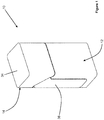
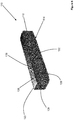
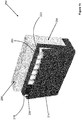
- FIGs 1 to 3 show a receptacle 10 according to a first embodiment of the present invention.
- the receptacle 10 comprises a box portion 12 and a cover portion 14 in the form of a lid portion depending from the box portion 12 along a hinge line 16.
- the cover portion 14 is rotatable about the hinge line 16 between a closed position (shown in Figure 1 ) and an open position (shown in Figure 3 ).
- a top end 18 of the box portion 12 defines a box opening 20 which is covered when the cover portion 14 is in the closed position and uncovered when the cover portion 14 is in the open position.
- the box portion 12 comprises a closed bottom end 22 opposite the top end 18.
- the receptacle 10 is sized to receive a plurality of used aerosol-generating articles 23 within the box portion 12.
- the box portion 12 comprises a box back wall 24, a box front wall 26, a first box side wall 28 and a second box side wall 30.
- the top edges of these walls together define the box opening 20 at the top end 18 of the box portion 12.
- a flange 32 extends around part of the box portion 12 at the top end 18 of the box portion 12.
- the box portion 12 also comprises a box bottom wall (not shown) that forms the closed bottom end 22 of the box portion 12.
- the closed bottom end 22 of the box portion 12 also forms a bottom end of the receptacle 10.
- a lid top wall 34 of the cover portion 14 forms a top end of the receptacle 10.
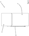
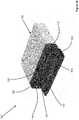
- Figure 5 shows a kit 50 comprising the receptacle 10 of Figures 1 to 4 and a container 52 for aerosol-generating articles.
- the container 52 is a hinged-lid container comprising a container box portion 54 and a container lid portion 56 depending from the container box portion 54 along a hinge line 58 extending between a container lid back wall 60 and a container box back wall 62.
- the clip 36 can be used to attach the receptacle 10 to a first container box side wall 64 of the container 52.
- the angular profile of the top end 40 of the clip 36 matches the angular profile of the top edge of the first container box side wall 64 so that the container lid portion 56 can still be fully closed when the receptacle 10 is attached to the container 52.
- configuring the clip 36 for attachment of the receptacle 10 to a side wall of the container 52 results in the box openings of the receptacle 10 and the container 52 having the same orientation, which may facilitate use of the kit 50 by a user.
- the depth and height of the receptacle 10 matches the depth and height of the container 52 which may further facilitate use of the kit 50 by a user, for example by making the kit 50 easy to hold.
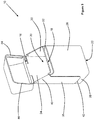
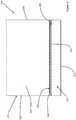
- the receptacle 110 comprises a box portion 112 and a cover portion 114 in the form of a lid portion depending from the box portion 112 along a hinge line 116.
- the cover portion 114 is rotatable about the hinge line 116 between a closed position (shown in Figure 6 ) and an open position (shown in Figure 10 ).
- a bottom end 118 of the box portion 112 defines a box opening 120 which is covered when the cover portion 114 is in the closed position and uncovered when the cover portion 114 is in the open position.
- the box portion 112 comprises a closed top end 122 opposite the bottom end 118.
- the box portion 112 comprises a box back wall 124, a box front wall 126, a first box side wall 128 and a second box side wall 130.
- the bottom edges of these walls together define the box opening 120 at the bottom end 118 of the box portion 112.
- a tab 132 extends from an edge of the cover portion 114 and is configured to engage a corresponding recess 133 in the bottom edge of the box front wall 126 by a snap fit, when the cover portion 114 is in the closed position.
- the snap fit forms a closure to retain the cover portion 114 in the closed position.
- the box portion 112 also comprises a box top wall 135 that forms the closed top end 122 of the box portion 112.
- the closed top end 122 of the box portion 112 also forms a top end of the receptacle 110.
- a lid bottom wall 134 of the cover portion 114 forms a bottom end of the receptacle 110.
- the receptacle 110 further comprises a clip 136 depending from the box portion 112 and overlying an outer surface of the box top wall 135.
- the clip 136 comprises a first portion 138 extending between a first end 140 and a free end 142 distal from the first end 140.
- a second portion (not shown) of the clip 136 is positioned inside the box portion 112 and secured to an inner surface of the box portion 112 by an adhesive.
- the clip 136 is formed from a resilient metal so that the clip 136 is biased towards the box top wall 135.
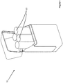
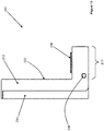
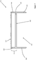
- Figures 11 to 13 show a receptacle 210 in accordance with a third embodiment of the present invention.
- Figures 14 and 15 show a kit 250 comprising the receptacle 210 and a container 252 for aerosol-generating articles.
- the receptacle 210 comprises a box portion 212, a base portion 213 and a cover portion 214 depending from the base portion 213 by a hinge 216.
- the cover portion 214 is rotatable about the hinge 216 between a closed position (shown in Figures 11 to 14 ) and an open position (shown in Figure 15 ).
- a back end 218 of the box portion 212 defines a box opening 220 which is covered when the cover portion 214 is in the closed position and uncovered when the cover portion 214 is in the open position.
- the box portion 212 comprises a closed front end 222 opposite the back end 218.
- the box portion 212 comprises a box top wall 226, a first box side wall 228 and a second box side wall 230. The back edges of these walls together define the box opening 220 at the back end 218 of the box portion 212.
- the box portion 212 also comprises a box front wall 224 that forms the closed front end 222 of the box portion 212.
- the base portion 213 extends from the closed front end 222 of the box portion 212.
- the base portion 213 comprises a base top wall 215 orthogonal to the closed front end 222 of the box portion 212 and a base bottom wall 217 opposite the base top wall 215.
- the receptacle 210 further comprises a clip 236 depending from the base portion 213 and overlying an outer surface of the base top wall 215.
- the clip 236 comprises a first portion 238 extending between a first end 240 and a free end 242 distal from the first end 240.
- a second portion (not shown) of the clip 236 is positioned inside the base portion 213 and secured to an inner surface of the base portion 213 by an adhesive.
- the clip 236 is formed from a resilient metal so that the clip 236 is biased towards the base top wall 215.
- the container 252 is a hinged-lid container comprising a container box portion 254 and a container lid portion 256 depending from the container box portion 254 along a hinge line.
- the clip 236 can be used to attach the receptacle 210 to a container box bottom wall 264 of the container 252 by inserting the clip through an aperture between a bottom edge of a first container box side wall 266 and the container box bottom wall 264.
- the closed front end 222 of the receptacle box portion 212 overlies a portion of a container back wall 268 of the container box portion 254.
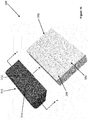
- Figures 16 to 19 show a receptacle 310 according to a fourth embodiment of the present invention and a kit 350 comprising the receptacle 310 and a container 352 for aerosol-generating articles.
- the receptacle 310 comprises a box portion 312 and a cover portion 314 in the form of a lid portion depending from the box portion 312 along a hinge line 316.
- the cover portion 314 is rotatable about the hinge line 316 between a closed position (shown in Figures 16 to 18 ) and an open position (shown in Figure 19 ).
- a top end 318 of the box portion 312 defines a box opening 320 which is covered when the cover portion 314 is in the closed position and uncovered when the cover portion 314 is in the open position.
- the box portion 312 comprises a closed bottom end 322 opposite the top end 318.
- the receptacle 310 is sized to receive a plurality of used aerosol-generating articles 323 within the box portion 312.
- the box portion 312 comprises a box back wall 324, a box front wall 326, a first box side wall 328 and a second box side wall 330.
- the top edges of these walls together define the box opening 320 at the top end 318 of the box portion 312.
- a tab 332 extends from an edge of the cover portion 314 and is configured to engage a corresponding recess 333 in the top edge of the box front wall 326 by a snap fit, when the cover portion 314 is in the closed position.
- the snap fit forms a closure to retain the cover portion 314 in the closed position.
- the box portion 312 also comprises a box bottom wall 335 that forms the closed bottom end 322 of the box portion 312.
- the receptacle 310 further comprises a skirt portion 336 extending from the box portion 312 about a periphery of the closed bottom end 322 of the box portion 312.
- the skirt portion 336 is formed integrally with the box portion 312.
- the skirt portion 336 defines a cavity 338 for receiving a portion of the container 352.
- the container 352 is a hinged-lid container comprising a container box portion 354 and a container lid portion 356 depending from the container box portion 354 along a hinge line.
- the receptacle 310 may be attached to the container 352 by inserting the container lid portion 356 into the cavity 338 defined by the skirt portion 336.
- the container lid portion 356 is retained within the cavity 338 by an interference fit.
- the shape of the skirt portion 336 corresponds to the shape of the container lid portion 356 so that only the container lid portion 356 is received within the cavity 338 when the receptacle 310 is attached to the contain 352.
- this permits opening and closing of the container lid portion 356 when the receptacle 310 is attached to the container 352. That is, the receptacle 310 moves with the container lid portion 356 when the container lid portion 356 is moved between open and closed positions.
Landscapes
- Engineering & Computer Science (AREA)
- Mechanical Engineering (AREA)
- Containers And Packaging Bodies Having A Special Means To Remove Contents (AREA)
- Stackable Containers (AREA)
- Packages (AREA)
Applications Claiming Priority (2)
| Application Number | Priority Date | Filing Date | Title |
|---|---|---|---|
| EP17191472 | 2017-09-15 | ||
| PCT/EP2018/074971 WO2019053230A1 (en) | 2017-09-15 | 2018-09-14 | RECEPTACLE FOR AEROSOL GENERATING ARTICLES |
Publications (2)
| Publication Number | Publication Date |
|---|---|
| EP3681816A1 EP3681816A1 (en) | 2020-07-22 |
| EP3681816B1 true EP3681816B1 (en) | 2021-10-27 |
Family
ID=59895192
Family Applications (1)
| Application Number | Title | Priority Date | Filing Date |
|---|---|---|---|
| EP18765919.8A Active EP3681816B1 (en) | 2017-09-15 | 2018-09-14 | A receptacle for aerosol-generating articles |
Country Status (7)
| Country | Link |
|---|---|
| US (1) | US20200275692A1 (https=) |
| EP (1) | EP3681816B1 (https=) |
| JP (1) | JP7417518B2 (https=) |
| KR (1) | KR102738605B1 (https=) |
| CN (1) | CN111065586B (https=) |
| RU (1) | RU2769208C2 (https=) |
| WO (1) | WO2019053230A1 (https=) |
Families Citing this family (2)
| Publication number | Priority date | Publication date | Assignee | Title |
|---|---|---|---|---|
| JP7614183B2 (ja) * | 2019-09-13 | 2025-01-15 | フィリップ・モーリス・プロダクツ・ソシエテ・アノニム | 拡張機能付き充電器ドアカバー |
| GB202016563D0 (en) * | 2020-10-19 | 2020-12-02 | Nicoventures Trading Ltd | Aerosol provision system |
Family Cites Families (26)
| Publication number | Priority date | Publication date | Assignee | Title |
|---|---|---|---|---|
| US2536725A (en) * | 1947-06-24 | 1951-01-02 | Ralph E Cleveland | Golf bag attached article carrier |
| US2781761A (en) * | 1953-09-14 | 1957-02-19 | Edwin B Royle | Pocxet ash tray |
| US3857482A (en) * | 1973-11-12 | 1974-12-31 | R Shelton | Display tray |
| JPS54109689U (https=) * | 1978-01-19 | 1979-08-02 | ||
| US4252237A (en) * | 1980-03-17 | 1981-02-24 | Baclit Paul S | Cigarette package holder combination |
| FR2600504B1 (fr) * | 1986-05-28 | 1988-10-21 | Letty Pascal | Support pour paquets de cigarettes |
| FR2684273B1 (fr) * | 1991-12-03 | 1994-06-10 | Maurel Nicolas | Dispositif formant un distributeur d'allumettes avec son grattoir. |
| JPH0610133U (ja) * | 1992-07-17 | 1994-02-08 | 大関株式会社 | ボトル収納容器の連結具 |
| GB9419304D0 (en) * | 1994-09-24 | 1994-11-09 | Imp Tobacco Co Ltd | Packs for smoking articles |
| JPH09224634A (ja) * | 1996-02-21 | 1997-09-02 | Hideo Yamamoto | 携帯用吸い殻入れ |
| JP3944983B2 (ja) * | 1997-12-26 | 2007-07-18 | ぺんてる株式会社 | クリップの軸筒への取り付け構造 |
| JP3052296U (ja) | 1998-03-16 | 1998-09-14 | 善弘 川▲崎▼ | 携帯用小型吸殻入れ |
| DE29912767U1 (de) * | 1999-07-21 | 1999-10-28 | König, Joachim, 84494 Niederbergkirchen | Feuerzeughalter für Zigarettenschachtel |
| JP2001269158A (ja) * | 2000-01-17 | 2001-10-02 | Hidemasa Matano | ライターの保持具 |
| DE20301248U1 (de) * | 2003-01-28 | 2003-06-18 | Eickholt, Frank, Dipl.-Designer, 48151 Münster | Vorrichtung um eine Zigarettenschachtel an einem Kleidungsstück zu befestigen |
| WO2005089577A1 (en) | 2004-03-16 | 2005-09-29 | Emc International Pty Ltd | A portable container for holding waste materials |
| US7334616B2 (en) * | 2004-10-12 | 2008-02-26 | Kaminski Scott T | Card-holding and money clip device |
| JP2006304718A (ja) * | 2005-04-28 | 2006-11-09 | Banpresto Co Ltd | 煙草箱カバー体 |
| CN101143027A (zh) * | 2006-09-15 | 2008-03-19 | 安东尼·包蒂斯塔 | 可附接到烟盒的小件物品配发装置 |
| CN200971189Y (zh) * | 2006-09-29 | 2007-11-07 | 孙明远 | 组合式瓶罐 |
| CN201484893U (zh) | 2009-09-29 | 2010-05-26 | 王铁苗 | 一种能够放置烟头的烟盒 |
| JP2013192529A (ja) | 2012-03-22 | 2013-09-30 | Makoto Ishizaka | 携帯用タバコ消火収納具 |
| RU137972U1 (ru) * | 2013-10-08 | 2014-02-27 | Татьяна Вячеславовна Трифонова | Пачка для сигарет |
| JP6242225B2 (ja) * | 2014-02-03 | 2017-12-06 | 村角工業株式会社 | 収納ケース |
| JP3191727U (ja) | 2014-02-28 | 2014-07-10 | 光男 岩岡 | 容器収納吊り棚 |
| WO2015136700A1 (ja) * | 2014-03-14 | 2015-09-17 | 日本たばこ産業株式会社 | パッケージ |
-
2018
- 2018-09-14 US US16/645,595 patent/US20200275692A1/en not_active Abandoned
- 2018-09-14 EP EP18765919.8A patent/EP3681816B1/en active Active
- 2018-09-14 JP JP2020514670A patent/JP7417518B2/ja active Active
- 2018-09-14 KR KR1020207005740A patent/KR102738605B1/ko active Active
- 2018-09-14 CN CN201880054252.9A patent/CN111065586B/zh active Active
- 2018-09-14 RU RU2020108063A patent/RU2769208C2/ru active
- 2018-09-14 WO PCT/EP2018/074971 patent/WO2019053230A1/en not_active Ceased
Also Published As
| Publication number | Publication date |
|---|---|
| CN111065586A (zh) | 2020-04-24 |
| JP2020533001A (ja) | 2020-11-19 |
| US20200275692A1 (en) | 2020-09-03 |
| WO2019053230A1 (en) | 2019-03-21 |
| KR20200054954A (ko) | 2020-05-20 |
| CN111065586B (zh) | 2022-09-23 |
| KR102738605B1 (ko) | 2024-12-05 |
| RU2020108063A3 (https=) | 2022-01-25 |
| RU2769208C2 (ru) | 2022-03-29 |
| BR112020002653A2 (pt) | 2020-08-18 |
| RU2020108063A (ru) | 2021-10-15 |
| EP3681816A1 (en) | 2020-07-22 |
| JP7417518B2 (ja) | 2024-01-18 |
Similar Documents
| Publication | Publication Date | Title |
|---|---|---|
| US7823731B2 (en) | Cigarette package | |
| USD591900S1 (en) | Moist snuff container for use with cigarette pack | |
| US20110303567A1 (en) | Package for Tobacco Products | |
| EP3326931B1 (en) | Container with hinge lid | |
| RU2624718C2 (ru) | Емкость с выдвижным элементом для выдачи потребительских товаров | |
| EP3681816B1 (en) | A receptacle for aerosol-generating articles | |
| EP1466844A1 (en) | Package with sliding lid | |
| EA019129B1 (ru) | Контейнер с шарнирной крышкой и выдвижным элементом | |
| EP3710369B1 (en) | Container for consumer goods including dispensing means | |
| US20020020640A1 (en) | Packaging system with a receptacle for storing debris | |
| EP3732077B1 (en) | A holder for holding an aerosol-generating device and a packet of aerosol-generating articles | |
| KR102796259B1 (ko) | 포장, 포장용 봉투, 및 봉투 제작용 블랭크 | |
| WO2011138184A1 (en) | A package for tobacco products | |
| BR112020002653B1 (pt) | Receptáculo para armazenamento de um ou mais artigos geradores de aerossol e kit | |
| WO2017088034A1 (en) | Receptacle for cigarette waste configured for being assembled to a cigarette pack and cigarette pack comprising such receptacle | |
| EP3047740A1 (en) | A container for smoking apparatus | |
| WO2018002844A1 (en) | Container for consumer goods including dispensing device | |
| HK1171726A1 (en) | Container comprising smoking articles with a lifting element |
Legal Events
| Date | Code | Title | Description |
|---|---|---|---|
| STAA | Information on the status of an ep patent application or granted ep patent |
Free format text: STATUS: UNKNOWN |
|
| STAA | Information on the status of an ep patent application or granted ep patent |
Free format text: STATUS: THE INTERNATIONAL PUBLICATION HAS BEEN MADE |
|
| PUAI | Public reference made under article 153(3) epc to a published international application that has entered the european phase |
Free format text: ORIGINAL CODE: 0009012 |
|
| STAA | Information on the status of an ep patent application or granted ep patent |
Free format text: STATUS: REQUEST FOR EXAMINATION WAS MADE |
|
| 17P | Request for examination filed |
Effective date: 20200313 |
|
| AK | Designated contracting states |
Kind code of ref document: A1 Designated state(s): AL AT BE BG CH CY CZ DE DK EE ES FI FR GB GR HR HU IE IS IT LI LT LU LV MC MK MT NL NO PL PT RO RS SE SI SK SM TR |
|
| AX | Request for extension of the european patent |
Extension state: BA ME |
|
| DAV | Request for validation of the european patent (deleted) | ||
| DAX | Request for extension of the european patent (deleted) | ||
| GRAP | Despatch of communication of intention to grant a patent |
Free format text: ORIGINAL CODE: EPIDOSNIGR1 |
|
| STAA | Information on the status of an ep patent application or granted ep patent |
Free format text: STATUS: GRANT OF PATENT IS INTENDED |
|
| INTG | Intention to grant announced |
Effective date: 20210517 |
|
| GRAS | Grant fee paid |
Free format text: ORIGINAL CODE: EPIDOSNIGR3 |
|
| GRAA | (expected) grant |
Free format text: ORIGINAL CODE: 0009210 |
|
| STAA | Information on the status of an ep patent application or granted ep patent |
Free format text: STATUS: THE PATENT HAS BEEN GRANTED |
|
| AK | Designated contracting states |
Kind code of ref document: B1 Designated state(s): AL AT BE BG CH CY CZ DE DK EE ES FI FR GB GR HR HU IE IS IT LI LT LU LV MC MK MT NL NO PL PT RO RS SE SI SK SM TR |
|
| REG | Reference to a national code |
Ref country code: GB Ref legal event code: FG4D |
|
| REG | Reference to a national code |
Ref country code: CH Ref legal event code: EP |
|
| REG | Reference to a national code |
Ref country code: AT Ref legal event code: REF Ref document number: 1441594 Country of ref document: AT Kind code of ref document: T Effective date: 20211115 |
|
| REG | Reference to a national code |
Ref country code: DE Ref legal event code: R096 Ref document number: 602018025751 Country of ref document: DE |
|
| REG | Reference to a national code |
Ref country code: IE Ref legal event code: FG4D |
|
| REG | Reference to a national code |
Ref country code: NL Ref legal event code: FP |
|
| REG | Reference to a national code |
Ref country code: LT Ref legal event code: MG9D |
|
| REG | Reference to a national code |
Ref country code: AT Ref legal event code: MK05 Ref document number: 1441594 Country of ref document: AT Kind code of ref document: T Effective date: 20211027 |
|
| PG25 | Lapsed in a contracting state [announced via postgrant information from national office to epo] |
Ref country code: RS Free format text: LAPSE BECAUSE OF FAILURE TO SUBMIT A TRANSLATION OF THE DESCRIPTION OR TO PAY THE FEE WITHIN THE PRESCRIBED TIME-LIMIT Effective date: 20211027 Ref country code: LT Free format text: LAPSE BECAUSE OF FAILURE TO SUBMIT A TRANSLATION OF THE DESCRIPTION OR TO PAY THE FEE WITHIN THE PRESCRIBED TIME-LIMIT Effective date: 20211027 Ref country code: FI Free format text: LAPSE BECAUSE OF FAILURE TO SUBMIT A TRANSLATION OF THE DESCRIPTION OR TO PAY THE FEE WITHIN THE PRESCRIBED TIME-LIMIT Effective date: 20211027 Ref country code: BG Free format text: LAPSE BECAUSE OF FAILURE TO SUBMIT A TRANSLATION OF THE DESCRIPTION OR TO PAY THE FEE WITHIN THE PRESCRIBED TIME-LIMIT Effective date: 20220127 Ref country code: AT Free format text: LAPSE BECAUSE OF FAILURE TO SUBMIT A TRANSLATION OF THE DESCRIPTION OR TO PAY THE FEE WITHIN THE PRESCRIBED TIME-LIMIT Effective date: 20211027 |
|
| PG25 | Lapsed in a contracting state [announced via postgrant information from national office to epo] |
Ref country code: IS Free format text: LAPSE BECAUSE OF FAILURE TO SUBMIT A TRANSLATION OF THE DESCRIPTION OR TO PAY THE FEE WITHIN THE PRESCRIBED TIME-LIMIT Effective date: 20220227 Ref country code: SE Free format text: LAPSE BECAUSE OF FAILURE TO SUBMIT A TRANSLATION OF THE DESCRIPTION OR TO PAY THE FEE WITHIN THE PRESCRIBED TIME-LIMIT Effective date: 20211027 Ref country code: PT Free format text: LAPSE BECAUSE OF FAILURE TO SUBMIT A TRANSLATION OF THE DESCRIPTION OR TO PAY THE FEE WITHIN THE PRESCRIBED TIME-LIMIT Effective date: 20220228 Ref country code: PL Free format text: LAPSE BECAUSE OF FAILURE TO SUBMIT A TRANSLATION OF THE DESCRIPTION OR TO PAY THE FEE WITHIN THE PRESCRIBED TIME-LIMIT Effective date: 20211027 Ref country code: NO Free format text: LAPSE BECAUSE OF FAILURE TO SUBMIT A TRANSLATION OF THE DESCRIPTION OR TO PAY THE FEE WITHIN THE PRESCRIBED TIME-LIMIT Effective date: 20220127 Ref country code: LV Free format text: LAPSE BECAUSE OF FAILURE TO SUBMIT A TRANSLATION OF THE DESCRIPTION OR TO PAY THE FEE WITHIN THE PRESCRIBED TIME-LIMIT Effective date: 20211027 Ref country code: HR Free format text: LAPSE BECAUSE OF FAILURE TO SUBMIT A TRANSLATION OF THE DESCRIPTION OR TO PAY THE FEE WITHIN THE PRESCRIBED TIME-LIMIT Effective date: 20211027 Ref country code: GR Free format text: LAPSE BECAUSE OF FAILURE TO SUBMIT A TRANSLATION OF THE DESCRIPTION OR TO PAY THE FEE WITHIN THE PRESCRIBED TIME-LIMIT Effective date: 20220128 Ref country code: ES Free format text: LAPSE BECAUSE OF FAILURE TO SUBMIT A TRANSLATION OF THE DESCRIPTION OR TO PAY THE FEE WITHIN THE PRESCRIBED TIME-LIMIT Effective date: 20211027 |
|
| REG | Reference to a national code |
Ref country code: DE Ref legal event code: R097 Ref document number: 602018025751 Country of ref document: DE |
|
| PG25 | Lapsed in a contracting state [announced via postgrant information from national office to epo] |
Ref country code: SM Free format text: LAPSE BECAUSE OF FAILURE TO SUBMIT A TRANSLATION OF THE DESCRIPTION OR TO PAY THE FEE WITHIN THE PRESCRIBED TIME-LIMIT Effective date: 20211027 Ref country code: SK Free format text: LAPSE BECAUSE OF FAILURE TO SUBMIT A TRANSLATION OF THE DESCRIPTION OR TO PAY THE FEE WITHIN THE PRESCRIBED TIME-LIMIT Effective date: 20211027 Ref country code: RO Free format text: LAPSE BECAUSE OF FAILURE TO SUBMIT A TRANSLATION OF THE DESCRIPTION OR TO PAY THE FEE WITHIN THE PRESCRIBED TIME-LIMIT Effective date: 20211027 Ref country code: EE Free format text: LAPSE BECAUSE OF FAILURE TO SUBMIT A TRANSLATION OF THE DESCRIPTION OR TO PAY THE FEE WITHIN THE PRESCRIBED TIME-LIMIT Effective date: 20211027 Ref country code: DK Free format text: LAPSE BECAUSE OF FAILURE TO SUBMIT A TRANSLATION OF THE DESCRIPTION OR TO PAY THE FEE WITHIN THE PRESCRIBED TIME-LIMIT Effective date: 20211027 Ref country code: CZ Free format text: LAPSE BECAUSE OF FAILURE TO SUBMIT A TRANSLATION OF THE DESCRIPTION OR TO PAY THE FEE WITHIN THE PRESCRIBED TIME-LIMIT Effective date: 20211027 |
|
| PLBE | No opposition filed within time limit |
Free format text: ORIGINAL CODE: 0009261 |
|
| STAA | Information on the status of an ep patent application or granted ep patent |
Free format text: STATUS: NO OPPOSITION FILED WITHIN TIME LIMIT |
|
| 26N | No opposition filed |
Effective date: 20220728 |
|
| PG25 | Lapsed in a contracting state [announced via postgrant information from national office to epo] |
Ref country code: AL Free format text: LAPSE BECAUSE OF FAILURE TO SUBMIT A TRANSLATION OF THE DESCRIPTION OR TO PAY THE FEE WITHIN THE PRESCRIBED TIME-LIMIT Effective date: 20211027 |
|
| PG25 | Lapsed in a contracting state [announced via postgrant information from national office to epo] |
Ref country code: SI Free format text: LAPSE BECAUSE OF FAILURE TO SUBMIT A TRANSLATION OF THE DESCRIPTION OR TO PAY THE FEE WITHIN THE PRESCRIBED TIME-LIMIT Effective date: 20211027 |
|
| PG25 | Lapsed in a contracting state [announced via postgrant information from national office to epo] |
Ref country code: MC Free format text: LAPSE BECAUSE OF FAILURE TO SUBMIT A TRANSLATION OF THE DESCRIPTION OR TO PAY THE FEE WITHIN THE PRESCRIBED TIME-LIMIT Effective date: 20211027 |
|
| REG | Reference to a national code |
Ref country code: BE Ref legal event code: MM Effective date: 20220930 |
|
| PG25 | Lapsed in a contracting state [announced via postgrant information from national office to epo] |
Ref country code: LU Free format text: LAPSE BECAUSE OF NON-PAYMENT OF DUE FEES Effective date: 20220914 |
|
| P01 | Opt-out of the competence of the unified patent court (upc) registered |
Effective date: 20230529 |
|
| PG25 | Lapsed in a contracting state [announced via postgrant information from national office to epo] |
Ref country code: IE Free format text: LAPSE BECAUSE OF NON-PAYMENT OF DUE FEES Effective date: 20220914 |
|
| PG25 | Lapsed in a contracting state [announced via postgrant information from national office to epo] |
Ref country code: BE Free format text: LAPSE BECAUSE OF NON-PAYMENT OF DUE FEES Effective date: 20220930 |
|
| PG25 | Lapsed in a contracting state [announced via postgrant information from national office to epo] |
Ref country code: CY Free format text: LAPSE BECAUSE OF FAILURE TO SUBMIT A TRANSLATION OF THE DESCRIPTION OR TO PAY THE FEE WITHIN THE PRESCRIBED TIME-LIMIT Effective date: 20211027 |
|
| PG25 | Lapsed in a contracting state [announced via postgrant information from national office to epo] |
Ref country code: MK Free format text: LAPSE BECAUSE OF FAILURE TO SUBMIT A TRANSLATION OF THE DESCRIPTION OR TO PAY THE FEE WITHIN THE PRESCRIBED TIME-LIMIT Effective date: 20211027 Ref country code: HU Free format text: LAPSE BECAUSE OF FAILURE TO SUBMIT A TRANSLATION OF THE DESCRIPTION OR TO PAY THE FEE WITHIN THE PRESCRIBED TIME-LIMIT; INVALID AB INITIO Effective date: 20180914 |
|
| PG25 | Lapsed in a contracting state [announced via postgrant information from national office to epo] |
Ref country code: TR Free format text: LAPSE BECAUSE OF FAILURE TO SUBMIT A TRANSLATION OF THE DESCRIPTION OR TO PAY THE FEE WITHIN THE PRESCRIBED TIME-LIMIT Effective date: 20211027 |
|
| PG25 | Lapsed in a contracting state [announced via postgrant information from national office to epo] |
Ref country code: MT Free format text: LAPSE BECAUSE OF FAILURE TO SUBMIT A TRANSLATION OF THE DESCRIPTION OR TO PAY THE FEE WITHIN THE PRESCRIBED TIME-LIMIT Effective date: 20211027 |
|
| REG | Reference to a national code |
Ref country code: CH Ref legal event code: U11 Free format text: ST27 STATUS EVENT CODE: U-0-0-U10-U11 (AS PROVIDED BY THE NATIONAL OFFICE) Effective date: 20251001 |
|
| PGFP | Annual fee paid to national office [announced via postgrant information from national office to epo] |
Ref country code: DE Payment date: 20250919 Year of fee payment: 8 |
|
| PGFP | Annual fee paid to national office [announced via postgrant information from national office to epo] |
Ref country code: NL Payment date: 20250918 Year of fee payment: 8 Ref country code: IT Payment date: 20250918 Year of fee payment: 8 |
|
| PGFP | Annual fee paid to national office [announced via postgrant information from national office to epo] |
Ref country code: GB Payment date: 20250919 Year of fee payment: 8 |
|
| PGFP | Annual fee paid to national office [announced via postgrant information from national office to epo] |
Ref country code: FR Payment date: 20250922 Year of fee payment: 8 |
|
| PGFP | Annual fee paid to national office [announced via postgrant information from national office to epo] |
Ref country code: CH Payment date: 20251001 Year of fee payment: 8 |