EP3680974B1 - Redox-flow-batterie-zelle, redox-flow-batterie-zellenstapel und redox-flow-batterie - Google Patents
Redox-flow-batterie-zelle, redox-flow-batterie-zellenstapel und redox-flow-batterie Download PDFInfo
- Publication number
- EP3680974B1 EP3680974B1 EP17863279.0A EP17863279A EP3680974B1 EP 3680974 B1 EP3680974 B1 EP 3680974B1 EP 17863279 A EP17863279 A EP 17863279A EP 3680974 B1 EP3680974 B1 EP 3680974B1
- Authority
- EP
- European Patent Office
- Prior art keywords
- overlapping region
- cell
- redox flow
- positive electrode
- negative electrode
- Prior art date
- Legal status (The legal status is an assumption and is not a legal conclusion. Google has not performed a legal analysis and makes no representation as to the accuracy of the status listed.)
- Active
Links
Images



Classifications
-
- H—ELECTRICITY
- H01—ELECTRIC ELEMENTS
- H01M—PROCESSES OR MEANS, e.g. BATTERIES, FOR THE DIRECT CONVERSION OF CHEMICAL ENERGY INTO ELECTRICAL ENERGY
- H01M8/00—Fuel cells; Manufacture thereof
- H01M8/18—Regenerative fuel cells, e.g. redox flow batteries or secondary fuel cells
- H01M8/184—Regeneration by electrochemical means
- H01M8/188—Regeneration by electrochemical means by recharging of redox couples containing fluids; Redox flow type batteries
-
- H—ELECTRICITY
- H01—ELECTRIC ELEMENTS
- H01M—PROCESSES OR MEANS, e.g. BATTERIES, FOR THE DIRECT CONVERSION OF CHEMICAL ENERGY INTO ELECTRICAL ENERGY
- H01M8/00—Fuel cells; Manufacture thereof
- H01M8/18—Regenerative fuel cells, e.g. redox flow batteries or secondary fuel cells
-
- H—ELECTRICITY
- H01—ELECTRIC ELEMENTS
- H01M—PROCESSES OR MEANS, e.g. BATTERIES, FOR THE DIRECT CONVERSION OF CHEMICAL ENERGY INTO ELECTRICAL ENERGY
- H01M8/00—Fuel cells; Manufacture thereof
- H01M8/24—Grouping of fuel cells, e.g. stacking of fuel cells
- H01M8/2455—Grouping of fuel cells, e.g. stacking of fuel cells with liquid, solid or electrolyte-charged reactants
-
- H—ELECTRICITY
- H01—ELECTRIC ELEMENTS
- H01M—PROCESSES OR MEANS, e.g. BATTERIES, FOR THE DIRECT CONVERSION OF CHEMICAL ENERGY INTO ELECTRICAL ENERGY
- H01M8/00—Fuel cells; Manufacture thereof
- H01M8/24—Grouping of fuel cells, e.g. stacking of fuel cells
- H01M8/2459—Comprising electrode layers with interposed electrolyte compartment with possible electrolyte supply or circulation
-
- Y—GENERAL TAGGING OF NEW TECHNOLOGICAL DEVELOPMENTS; GENERAL TAGGING OF CROSS-SECTIONAL TECHNOLOGIES SPANNING OVER SEVERAL SECTIONS OF THE IPC; TECHNICAL SUBJECTS COVERED BY FORMER USPC CROSS-REFERENCE ART COLLECTIONS [XRACs] AND DIGESTS
- Y02—TECHNOLOGIES OR APPLICATIONS FOR MITIGATION OR ADAPTATION AGAINST CLIMATE CHANGE
- Y02E—REDUCTION OF GREENHOUSE GAS [GHG] EMISSIONS, RELATED TO ENERGY GENERATION, TRANSMISSION OR DISTRIBUTION
- Y02E60/00—Enabling technologies; Technologies with a potential or indirect contribution to GHG emissions mitigation
- Y02E60/30—Hydrogen technology
- Y02E60/50—Fuel cells
Definitions
- the present invention relates to a redox flow battery cell, a redox flow battery cell stack, and a redox flow battery.
- Patent Literature 1 discloses a cell stack in which cell frames, positive electrodes, membranes (ion-exchange membranes), and negative electrodes are repeatedly stacked.
- a cell frame includes a frame body and a bipolar plate integrated with the frame body. In the cell stack, between the bipolar plates of adjacent cell frames, a positive electrode and a negative electrode are arranged with a membrane therebetween, thus constituting a cell.
- PTL 2 shows a redox flow battery cell and forms the basis for the preamble of claim 1.
- a redox flow battery cell according to the present invention is defined in claim 1.
- a redox flow battery cell stack according to the present disclosure includes the redox flow battery cells according to the present disclosure, the redox flow battery cells being repeatedly stacked.
- a redox flow battery according to the present disclosure includes the redox flow battery cell according to the present disclosure or the redox flow battery cell stack according to the present disclosure.
- An RF battery performs charging and discharging by circulating electrolytes, by using pumps, into a cell in which a positive electrode and a negative electrode are arranged so as to face each other with a membrane therebetween.
- pumps are driven by supplying power to the pumps from an external power system.
- the pumps stop and thus, electrolyte flow stops. Therefore, discharging from the RF battery to the power system cannot be performed even if discharging is desired. Accordingly, it is required to supply the necessary power to start pumps from the cell (or cell stack) so that the operation of the RF battery can be restarted on its own during power failure in the power system.
- the pumps can be started by using power generated by discharging of the electrolyte between positive and negative electrodes in the cell.
- the area of the positive electrode is equivalent to the area of the negative electrode, and the positive and negative electrodes are arranged such that the entire surfaces of the two electrodes overlap each other with a membrane therebetween. Therefore, battery reactions take place over the entire surfaces of the two electrodes.
- the electrolyte in the cell is in a discharged state, and it may not be possible to sufficiently secure the necessary power to start pumps by using the electrolyte remaining in the cell in some cases. Furthermore, self-discharge of the electrolyte between the two electrodes is likely to proceed, and during the downtime of the pumps, the power stored in the electrolyte in the cell is likely to be consumed by self-discharge. Therefore, there is a severe time constraint on the period from the stop of pumps due to power failure in the power system until the start of the pumps.
- an object of the present disclosure is to provide a redox flow battery cell and a redox flow battery cell stack in which the power for starting pumps can be supplied during power failure in a power system.
- Another object of the present disclosure is to provide a redox flow battery which can restart operation on its own during power failure in the power system.
- a redox flow battery cell and a redox flow battery cell stack in which the power for starting pumps can be supplied during power failure in a power system. Furthermore, according to the present disclosure, it is possible to provide a redox flow battery which can restart operation on its own during power failure in a power system.
- a redox flow battery cell includes a positive electrode, a negative electrode, and a membrane interposed between the positive electrode and the negative electrode.
- the positive electrode and the negative electrode have an overlapping region where the positive electrode and the negative electrode overlap each other with the membrane therebetween, and at least one of the positive electrode and the negative electrode has a non-overlapping region where the positive electrode and the negative electrode do not overlap each other with the membrane therebetween.
- the total area of the non-overlapping region is 0.1% to 20% of the area of the overlapping region.
- the positive electrode and the negative electrode are arranged so as to have an overlapping region and a non-overlapping region of the positive electrode and the negative electrode, and the total area of the non-overlapping region in the two electrodes is 0.1% to 20% of the area of the overlapping region.
- overlapping region refers to a region where the positive electrode and the negative electrode overlap each other when the positive electrode and the negative electrode are perspectively viewed from one side.
- non-overlapping region refers to a region, excluding the overlapping region, where the positive electrode and the negative electrode do not overlap each other.
- the overlapping region is a portion that contributes to the battery reaction between the two electrodes
- the non-overlapping region is a portion that does not contribute to the battery reaction between the two electrodes.
- At least one of the positive electrode and the negative electrode has a non-overlapping region. Since the non-overlapping region does not contribute to the battery reaction, the unreacted electrolyte that has not participated in the battery reaction is present in the non-overlapping region. That is, in the case where pumps stop during power failure in a power system and electrolyte flow stops, the unreacted electrolyte remains partially in the cell. During the downtime of the pumps, the unreacted electrolyte that is present in the non-overlapping region diffuses into the overlapping region, and accordingly, because of discharging between the two electrodes, the necessary power to start pumps can be supplied from the cell.
- the necessary power to start pumps can be secured by the electrolyte that has not participated in the battery reaction and is present in the non-overlapping region. Furthermore, even if self-discharge of the electrolyte proceeds in the overlapping region between the two electrodes during the downtime of the pumps, since the unreacted electrolyte that is present in the non-overlapping region diffuses into the overlapping region, the power stored in the unreacted electrolyte can be discharged over a long period of time. Accordingly, it is possible to ease the time constraint on the period from the stop of pumps due to power failure in the power system until the start of the pumps. Therefore, in the redox flow battery cell, the power for starting pumps during power failure in the power system can be supplied, and even under the condition where power is not supplied from the outside to the pumps, the pumps can be started.
- the total area of the non-overlapping region is 0.1% or more of the area of the overlapping region, by securing the amount of electrolyte flowing in the non-overlapping region, the necessary power to start pumps during power failure in the power system is easily secured.
- the area ratio of the non-overlapping region increases, the proportion of the electrolyte that flows in the non-overlapping region increases, and the amount of electrolyte flowing in the overlapping region decreases. Since the total area of the non-overlapping region is 20% or less of the area of the overlapping region, by securing the overlapping region that contributes to the battery reaction, a decrease in output during charging and discharging can be suppressed.
- each of the positive electrode and the negative electrode has the non-overlapping region.
- each of the positive electrode and the negative electrode has the non-overlapping region, the unreacted electrolyte is present in the non-overlapping region of each electrode. Therefore, it is possible to reliably cause discharging of the electrolyte between the two electrodes, and by supplying the necessary power to start pumps during power failure in the power system, the pumps can be reliably started.
- the positive electrode may have an area equivalent to that of the negative electrode.
- the positive electrode has an area equivalent to that of the negative electrode
- non-overlapping regions having the same area are formed in the positive electrode and the negative electrode, and the same amount of electrolyte flows in the non-overlapping region of each electrode. Therefore, it is possible to sufficiently cause discharging of the electrolyte between the two electrodes, and the necessary power to start pumps during power failure in the power system can be sufficiently supplied.
- the expression "the positive electrode has an area equivalent to that of the negative electrode” means that the two electrodes have substantially the same area. For example, when the difference in the area between the two electrodes is 0.01% or less of the area of each electrode, the areas of the two electrodes are considered to be equivalent to each other.
- the area of the positive electrode and the area of the negative electrode refer to the planar areas of the planes of the electrodes that face each other.
- the positive electrode and the negative electrode each may have a thickness of 0.05 mm or more.
- the thickness of each of the positive electrode and the negative electrode is the thickness of the electrode when arranged inside the cell.
- the thickness of each electrode refers to the thickness of the electrode in the compressed state.
- the positive electrode and the negative electrode each may have an area of 250 cm 2 or more.
- the two electrodes each have an area of 250 cm 2 or more, the area of each of the overlapping region and the non-overlapping region is sufficiently easily secured, and the amount of electrolyte flowing in each region is sufficiently easily secured. Accordingly, output during charging and discharging can be secured, and the necessary power to start pumps during power failure in the power system is sufficiently easily secured.
- a redox flow battery cell stack includes the redox flow battery cells according to any one of items (1) to (5), the redox flow battery cells being repeatedly stacked.
- the redox flow battery cell stack includes the redox flow battery cells according to the embodiment, it is possible to supply the power for starting pumps during power failure in the power system.
- the redox flow battery cell stack includes a plurality of cells, and it is possible to secure the necessary power to start pumps by using the unreacted electrolyte present in the non-overlapping region in each cell. Accordingly, the necessary power to start pumps can be sufficiently supplied from the cell stack.
- a redox flow battery according to an embodiment includes the redox flow battery cell according to any one of items (1) to (5) or the redox flow battery cell stack according to item (6).
- the redox flow battery includes the redox flow battery cell or redox flow battery cell stack according to the embodiment, the necessary power to start pumps during power failure in the power system can be supplied from the cell or cell stack, and the pumps can be started. Accordingly, the redox flow battery can restart operation on its own during power failure in the power system.
- a redox flow battery cell hereinafter, may be simply referred to as the "cell”
- a redox flow battery cell stack hereinafter, may be simply referred to as the "cell stack”
- RF battery redox flow battery
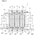
- the RF battery 1 shown in Figs. 1 and 2 uses a positive electrode electrolyte and a negative electrode electrolyte, each containing, as an active material, metal ions whose valence is changed by oxidation-reduction, and performs charging and discharging using the difference between the oxidation-reduction potential of ions contained in the positive electrode electrolyte and the oxidation-reduction potential of ions contained in the negative electrode electrolyte.
- the RF battery 1 is a vanadium-based RF battery which uses a vanadium electrolyte containing V ions serving as an active material for each of the positive electrode electrolyte and the negative electrode electrolyte.
- the solid line arrow indicates a charging reaction
- the dashed line arrow indicates a discharging reaction.
- the RF battery 1 is connected, through an alternating current/direct current converter C, to a power system L, and for example, is used for load leveling, for voltage sag compensation and emergency power sources, and for smoothing the output of natural energy, such as solar power generation or wind power generation that is being introduced on a massive scale.
- the RF battery 1 includes a cell 100 which includes a positive electrode 104, a negative electrode 105, and a membrane 101 interposed between the positive electrode 104 and the negative electrode 105 (refer to Fig. 1 ).
- the cell 100 is separated into a positive electrode cell 102 and a negative electrode cell 103 by a membrane 101 that allows hydrogen ions to permeate therethrough, and the positive electrode cell 102 and the negative electrode cell 103 contain the positive electrode 104 and the negative electrode 105, respectively.
- the positive electrode cell 102 is connected via ducts 108 and 110 to a positive electrode electrolyte tank 106 that stores a positive electrode electrolyte.
- the duct 108 is provided with a pump 112 for circulating the positive electrode electrolyte from the positive electrode electrolyte tank 106 to the positive electrode cell 102, and the members 106, 108, 110, and 112 constitute a positive electrolyte circulation mechanism 100P for circulating the positive electrode electrolyte.
- the negative electrode cell 103 is connected via ducts 109 and 111 to a negative electrode electrolyte tank 107 that stores a negative electrode electrolyte.
- the duct 109 is provided with a pump 113 for circulating the negative electrode electrolyte from the negative electrode electrolyte tank 107 to the negative electrode cell 103, and the members 107, 109, 111, and 113 constitute a negative electrolyte circulation mechanism 100N for circulating the negative electrode electrolyte.
- the pumps 112 and 113 are driven so that the positive and negative electrolytes are circulated within the cell 100 (positive electrode cell 102 and negative electrode cell 103).
- the pumps 112 and 113 are stopped so that circulation of the electrolytes is stopped.
- the pumps 112 and 113 are driven by supplying power to the pumps 112 and 113 from the power system L.
- the RF battery 1 includes a cell stack 2 in which cells 100 are repeatedly stacked.
- the cell stack 2 is configured such that a layered body referred to as a sub-stack 200 (refer to Fig. 3 ) is sandwiched between two end plates 220 and the end plates 220 on both sides are fastened with a fastening mechanism 230 (in the configuration illustrated in Fig. 3 , a plurality of sub-stacks 200 are included).
- the sub-stack 200 has a configuration in which cell fames 3, positive electrodes 104, membranes 101, and negative electrodes 105 are repeatedly stacked, and supply/drainage plates 210 (refer to the view shown in the lower part of Fig.
- the number of cells 100 stacked is, for example, 5 or more, 50 or more, or 100 or more.
- the upper limit of the number of cells 100 stacked is not particularly limited, but is, for example, 200 or less.
- a cell frame 3 includes a bipolar plate 31 which is disposed between a positive electrode 104 and a negative electrode 105, and a frame body 32 which is provided around the bipolar plate 31.
- the positive electrode 104 is disposed so as to be in contact with the one surface side of the bipolar plate 31, and the negative electrode 105 is disposed so as to be in contact with the other surface side of the bipolar plate 31.
- the bipolar plate 31 is provided inside the frame body 32, and a recess 32o is formed by the bipolar plate 31 and the frame body 32 (also refer to Fig. 4 ). Recesses 32o are formed on both sides of the bipolar plate 31 (in Fig.
- the one surface side of the frame body 32 of one of two adjacent cell frames 3 faces the other surface side of the frame body 32 of the other cell frame 3, and a cell 100 is formed between bipolar plates 31 of two adjacent cell frames 3.
- the bipolar plate 31 is, for example, made of carbon plastic or the like, and the frame body 32 is, for example, made of a plastic, such as a vinyl chloride resin (PVC), polypropylene, polyethylene, a fluorine resin, or an epoxy resin.
- the bipolar plate 31 is formed by a known method, such as injection molding, press molding, or vacuum forming.
- the frame body 32 is integrated around the bipolar plate 31 by injection molding or the like.
- the planar shape (shape viewed in plan) of the bipolar plate 31 is rectangular, and the frame body 32 is rectangular frame-shaped.
- Circulation of electrolytes to the cell 100 is performed, through supply/drainage plates 210 (refer to the lower part of Fig. 3 ), by liquid supply manifolds 33 and 34 and liquid discharge manifolds 35 and 36 which are provided so as to pass through the frame body 32 of the cell frame 3 shown in Fig. 3 and liquid supply slits 33s and 34s and liquid discharge slits 35s and 36s formed on the frame body 32 (also refer to Fig. 4 ).
- the positive electrode electrolyte is supplied from the liquid supply manifold 33 provided on the lower part of the frame body 32 through the liquid supply slit 33s formed on the one surface side (on the front side of the sheet in Fig.
- the negative electrode electrolyte is supplied from the liquid supply manifold 34 provided on the lower part of the frame body 32 through the liquid supply slit 34s formed on the other surface side (on the back side of the sheet in Fig. 4 ) of the frame body 32 to the negative electrode 105, and is discharged through the liquid discharge slit 36s formed on the upper part of the frame body 32 to the liquid discharge manifold 36.
- Rectifying portions may be formed along an inner lower edge and an inner upper edge of the frame body 32 on which the bipolar plate 31 is provided.
- the rectifying portions function to diffuse the electrolytes supplied from the liquid supply slits 33s and 34s along the lower edges of the electrodes 104 and 105, and to collect the electrolytes discharged from the upper edges of the electrodes 104 and 105 to the liquid discharge slits 35s and 36s.
- the electrolytes are supplied from the lower side of the positive electrode 104 and the negative electrode 105, and the electrolytes are discharged from the upper side of the electrodes 104 and 105.
- the electrolyte flows from the lower edge toward the upper edge (in Fig. 4 , the thick line arrow on the left side of the sheet indicates the overall direction in which the electrolytes flow).
- a plurality of groove portions may be formed on the surfaces of the bipolar plate 31 in contact with the electrodes 104 and 105 so as to extend in the direction in which the electrolytes flow. Thereby, the electrolyte flow resistance can be decreased, and the electrolyte pressure loss can be reduced.
- the cross-sectional shape (the shape of a cross section orthogonal to the electrolyte flowing direction) of the groove portion is not particularly limited, and may be, for example, rectangular, triangular (V-shaped), trapezoidal, semicircular, or semi-elliptic.
- ring-shaped sealing members 37 such as O-rings and flat packings, (refer to Figs. 2 and 3 ) are disposed between the frame bodies 32 of the cell frames 3 so that leakage of the electrolytes can be suppressed.
- the frame body 32 is provided with sealing grooves 38 (refer to Fig. 4 ) for disposing the sealing members 37.
- One of the characteristics of the cell 100 is the arrangement of the positive electrode 104 and the negative electrode 105 which are arranged so as to face each other with the membrane 101 therebetween.
- the positive electrode 104 and the negative electrode 105 have an overlapping region OA in which the positive electrode 104 and the negative electrode 105 overlap each other with the membrane 101 therebetween, and at least one of the positive electrode 104 and the negative electrode 105 has a non-overlapping region SA in which the positive electrode 104 and the negative electrode 105 do not overlap each other with the membrane 101 therebetween (refer to Fig. 5 ).
- the arrangement of the positive electrode 104 and the negative electrode 105 in the cell 100 will be described below with reference to mainly Fig. 5 . In Fig. 5 , the membrane is omitted.
- Each of the positive electrode 104 and the negative electrode 105 is a reaction site where the active material (ions) contained in the electrolyte causes a battery reaction.
- the electrodes 104 and 105 each can be made of a known material, and for example, are made of a nonwoven fabric (carbon felt) or woven fabric (carbon cloth) composed of carbon fibers, paper (carbon paper), or the like. In this example, the planar shape of each of the electrodes 104 and 105 is rectangular.
- the thickness of each of the electrodes 104 and 105 is not particularly limited, but is, for example, 0.05 mm or more, or 0.2 mm or more.
- the thickness of each of the electrodes 104 and 105 is 0.05 mm or more, by securing the amount of electrolyte flowing in each of the electrodes 104 and 105, output during charging and discharging is easily secured.
- the thickness of each of the electrodes 104 and 105 is the thickness of the electrode in the state in which the cell 100 (refer to Fig. 3 ) is assembled.
- the thickness refers to the thickness of the electrode in the compressed state.
- the depth of the recess 32o corresponds to the thickness of each of the electrodes 104 and 105.
- the upper limit of the thickness of each of the electrodes 104 and 105 is, for example, 3.0 mm or less.
- the area of each of the electrodes 104 and 105 is not particularly limited, but is, for example, 250 cm 2 or more, or 500 cm 2 or more. When the area of each of the electrodes 104 and 105 is 250 cm 2 or more, by securing the amount of electrolyte flowing in each of the electrodes 104 and 105, output during charging and discharging is easily secured.
- the area of the electrode 104 and the area of the electrode 105 refer to the planar areas of the planes of the electrodes that face each other.
- the electrodes 104 and 105 may have the same area or different areas. In this example, the area of the electrode 104 is equivalent to the area of the electrode 105.
- the upper limit of the area of each of the electrodes 104 and 105 is, for example, about 8,000 cm 2 .
- the positive electrode 104 and the negative electrode 105 are arranged such that the electrodes 104 and 105 have an overlapping region OA and each of the electrodes 104 and 105 has a non-overlapping region SA when viewed in plan.
- Fig. 5 shows an arrangement state of the positive electrode 104 and the negative electrode 105 in the cell 100 when perspectively viewed from the positive electrode 104 side.
- the positive electrode 104 and the negative electrode 105 are arranged so as to be shifted obliquely.
- the positive electrode 104 is moved obliquely toward the upper left and the negative electrode 105 is moved obliquely toward the lower right from the state in which the positive electrode 104 and the negative electrode 105 overlap each other with their centers coinciding with each other.
- the area of the positive electrode 104 is equivalent to the area of the negative electrode 105, and each of the positive electrode 104 and the negative electrode 105 has a non-overlapping region SA.
- the non-overlapping region SA of the positive electrode 104 and the non-overlapping region SA of the negative electrode 105 have the same area. In Fig.
- the overlapping region OA of the positive electrode 104 and the negative electrode 105 is indicated by double hatching
- the non-overlapping region SA of the positive electrode 104 is indicated by the hatching that slants to the upper right
- the non-overlapping region SA of the negative electrode 105 is indicated by the hatching that slants to the lower right.
- Fig. 5 shows an example in which the positive electrode 104 and the negative electrode 105 are arranged so as to be shifted obliquely.
- the positive electrode 104 and the negative electrode 105 may be arranged so as to be shifted in the upward-downward direction (in the longitudinal direction) or may be arranged so as to be shifted in the leftward-rightward direction (in the horizontal direction).
- the positive electrode 104 and the negative electrode 105 may have different areas, and one electrode having a small area may be arranged so as to entirely overlap the other electrode having a large area.
- one of the positive electrode 104 and the negative electrode 105 having a large area has a non-overlapping region SA, and the other electrode having a small area has only an overlapping region OA.
- one electrode having a small area can be arranged so as to partially protrude from the other electrode having a large area. In this case, the electrode having a small area can also have a non-overlapping region SA.
- protruding portions which protrude toward the electrode side may be formed on the inner peripheral surface of the frame body 32, or protruding portions which protrude toward the frame body 32 may be formed on the outer peripheral surfaces of the electrodes.
- the size of the protruding portions may be set such that the electrodes can be supported. In the case where protruding portions are formed on the outer peripheral surfaces of the electrodes, the size of the protruding portions may be set as small as possible in order to avoid an excessive increase in the overlapping region.
- the electrodes can be positioned by inserting separate positioning pieces (not shown) between the inner peripheral surface of the frame body 32 and the outer peripheral surface of each of the electrodes 104 and 105.
- the positioning pieces may be formed of a material having moderate flexibility and resistance to electrolyte (electrolyte resistance), such as rubber, sponge rubber, or a resin. Examples of the resin constituting the positioning pieces include polyethylene foam, urethane foam, and polystyrene foam.
- the unreacted electrolyte that has not participated in the battery reaction is present in the non-overlapping region SA.
- the non-overlapping region SA is a portion that does not contribute to the battery reaction between the electrodes 104 and 105, the electrolyte flows in an unreacted state in the non-overlapping region SA. That is, in the case where pumps 112 and 113 stop during power failure in the power system L and electrolyte flow stops (refer to Figs. 1 and 2 ), the unreacted electrolyte remains partially in the cell 100.
- the unreacted electrolyte present in the non-overlapping region SA diffuses into the overlapping region OA to cause a battery reaction between the electrodes 104 and 105, and thereby, the necessary power to start the pumps 112 and 113 can be supplied from the cell 100 (cell stack 2) during power failure.
- the unreacted electrolyte is present in each of the non-overlapping regions SA. Therefore, it is possible to reliably cause a battery reaction between the electrodes 104 and 105.
- the non-overlapping region SA in the positive electrode 104 and the non-overlapping region SA in the negative electrode 105 have the same area, and the same amount of electrode flows in the non-overlapping region SA in each electrode. Therefore, it is possible to sufficiently cause a battery reaction between the electrodes 104 and 105.
- the total area of the non-overlapping region in the positive electrode 104 and the negative electrode 105 is 0.1% to 20% of the area of the overlapping region OA. Since the total area of the non-overlapping region SA is 0.1% or more of the area of the overlapping region OA, by securing the amount of electrolyte flowing in the non-overlapping region SA, the necessary power to start the pumps 112 and 113 during power failure is easily secured. On the other hand, as the area ratio of the non-overlapping region SA (total area of non-overlapping region SA/area of overlapping region OA) increases, the proportion of the electrolyte that flows in the non-overlapping region increases, and the amount of electrolyte that flows in the overlapping region OA decreases.
- the total area of the non-overlapping region SA is 20% or less of the area of the overlapping region OA, by securing the overlapping region OA that contributes to the battery reaction, a decrease in output during charging and discharging can be suppressed.
- the total area of the non-overlapping region SA is, for example, 0.2% to 15% of the area of the overlapping region OA.
- the cell 100, the cell stack 2, and the RF battery 1 according to the embodiments have the following operational advantages.
- At least one of the positive electrode 104 and the negative electrode 105 has a non-overlapping region SA.
- the unreacted electrolyte that is present in the non-overlapping region SA diffuses into the overlapping region OA, and accordingly, because of discharging between the electrodes 104 and 105, the necessary power to start the pumps 112 and 113 can be discharged. Therefore, in the cell 100 according to the embodiment, the power for starting the pumps 112 and 113 can be supplied during power failure in the power system L.
- the pumps can be started.
- the necessary power to start the pumps 112 and 113 can be secured by the electrolyte that has not participated in the battery reaction and is present in the non-overlapping region SA in the cell 100.
- the total area of the non-overlapping region SA is 0.1% to 20% of the area of the overlapping region OA
- the amount of electrolyte flowing in each of the non-overlapping region SA and the overlapping region OA is moderately easily secured, the necessary power to start the pumps 112 and 113 during power failure is secured, and output during charging and discharging is easily secured in the normal operation.
- the unreacted electrolyte is present in the non-overlapping region SA of each of the electrodes 104 and 105. Therefore, it is possible to reliably cause discharging of the electrolyte between the electrodes 104 and 105, and by supplying the necessary power to start the pumps 112 and 113 during power failure, the pumps 112 and 113 can be reliably started. Furthermore, in the case where the area of the positive electrode 104 is equivalent to the area of the negative electrode 105, non-overlapping regions SA having the same area are formed in the positive electrode 104 and the negative electrode 105. Therefore, it is possible to sufficiently cause discharging of the electrolyte between the electrodes 104 and 105, and the necessary power to start the pumps 112 and 113 during power failure can be sufficiently supplied.
- the positive electrode 104 and the negative electrode 105 each have a thickness of 0.05 mm or more, the amount of electrolyte flowing in the non-overlapping region SA is sufficiently easily secured. Accordingly, the necessary power to start the pumps 112 and 113 during power failure is sufficiently easily secured.
- the positive electrode 104 and the negative electrode 105 each have an area of 250 cm 2 or more, the area of each of the overlapping region OA and the non-overlapping region SA is sufficiently easily secured, and the amount of electrolyte flowing in each region is sufficiently easily secured. Accordingly, output during charging and discharging can be secured, and the necessary power to start the pumps 112 and 113 during power failure is sufficiently easily secured.
- the cell stack 2 includes the cell 100 according to the embodiment, it is possible to supply the power for starting the pumps 112 and 113 during power failure in the power system L.
- the cell stack 2 includes a plurality of cells 100, and it is easy to secure the necessary power to start the pumps 112 and 113 by using the unreacted electrolyte present in the non-overlapping region SA in each cell 100. Accordingly, the necessary power to start the pumps 112 and 113 can be sufficiently supplied from the cell stack 2.
- the RF battery 1 according to the embodiment includes the cell 100 or cell stack 2 according to the embodiment, the necessary power to start the pumps 112 and 113 during power failure in the power system L can be supplied from the cell 100 or cell stack 2, and the pumps 112 and 113 can be started. Accordingly, the RF battery 1 according to the embodiment can restart operation on its own during power failure in the power system L.
- RF batteries (specimens A to D) with different arrangements of a positive electrode and a negative electrode in a cell were assembled, and by using the RF batteries, a pump start-up test was conducted.
- Multilayered bodies were formed by successively repeatedly stacking cell frames, positive electrodes, membranes, and negative electrodes, and cell stacks were fabricated. Electrodes made of carbon felt with the same shape and size were used as the positive electrodes and the negative electrodes. The positive electrodes and negative electrodes used had a rectangular planar shape, the same area, and the same thickness. The area was 250 cm 2 and the thickness was 0.3 mm. In each of the cell stacks, the number of cells stacked was 5.
- redox flow battery cells and redox flow battery cell stacks according to the embodiments can be suitably used for redox flow batteries.
Landscapes
- Life Sciences & Earth Sciences (AREA)
- Engineering & Computer Science (AREA)
- Manufacturing & Machinery (AREA)
- Sustainable Development (AREA)
- Sustainable Energy (AREA)
- Chemical & Material Sciences (AREA)
- Chemical Kinetics & Catalysis (AREA)
- Electrochemistry (AREA)
- General Chemical & Material Sciences (AREA)
- Fuel Cell (AREA)
Claims (6)
- Redox-Flow-Batteriezelle (100), die eine positive Elektrode (104), eine negative Elektrode (105) und eine zwischen der positiven Elektrode (104) und der negativen Elektrode (105) angeordnete Membrane (101) umfasst,wobei die positive Elektrode (104) und die negative Elektrode (105) einen überlappenden Bereich (OA) aufweisen, wobei die positive Elektrode (104) und die negative Elektrode (105) miteinander mit dazwischen der Membrane (101) überlappen, und wobei die positive Elektrode (104) und/oder die negative Elektrode (105) einen nicht-überlappenden Bereich (SA) aufweisen, in dem die positive Elektrode (104) und die negative Elektrode (105) nicht miteinander mit dazwischen der Membrane (101) überlappen,wobei die Gesamtfläche des nicht-überlappenden Bereichs (SA) 0,1% bis 20% der Fläche des überlappenden Bereichs (OA) ausmacht,dadurch gekennzeichnet, dass:
jede der positiven Elektrode (104) und der negativen Elektrode (105) den nicht-überlappenden Bereich (SA) aufweist. - Redox-Flow-Batteriezelle (100) nach Anspruch 1, wobei die positive Elektrode (104) eine Fläche aufweist, die derjenigen der negativen Elektrode (105) entspricht.
- Redox-Flow-Batteriezelle (100) nach Anspruch 1 oder 2, wobei die positive Elektrode (104) und die negative Elektrode (105) jeweils eine Dicke von 0,05 mm oder größer aufweisen.
- Redox-Flow-Batteriezelle (100) nach einem der Ansprüche 1 bis 3, wobei die positive Elektrode (104) und die negative Elektrode (105) jeweils eine Fläche von 250 cm2 oder größer aufweisen.
- Redox-Flow-Batteriezellenstapel (2), der die Redox-Flow-Batteriezellen (100) gemäß einem der Ansprüche 1 bis 4 umfasst, wobei die Redox-Flow-Batteriezellen (100) wiederholt gestapelt sind.
- Redox-Flow-Batterie (1), die die Redox-Flow-Batteriezelle (100) gemäß einem der Ansprüche 1 bis 4 oder den Redox-Flow-Batteriezellenstapel (2) gemäß Anspruch 5 umfasst.
Applications Claiming Priority (1)
| Application Number | Priority Date | Filing Date | Title |
|---|---|---|---|
| PCT/JP2017/032571 WO2019049333A1 (ja) | 2017-09-08 | 2017-09-08 | レドックスフロー電池セル、レドックスフロー電池セルスタック、及びレドックスフロー電池 |
Publications (3)
| Publication Number | Publication Date |
|---|---|
| EP3680974A1 EP3680974A1 (de) | 2020-07-15 |
| EP3680974A4 EP3680974A4 (de) | 2020-09-09 |
| EP3680974B1 true EP3680974B1 (de) | 2024-08-07 |
Family
ID=65633669
Family Applications (1)
| Application Number | Title | Priority Date | Filing Date |
|---|---|---|---|
| EP17863279.0A Active EP3680974B1 (de) | 2017-09-08 | 2017-09-08 | Redox-flow-batterie-zelle, redox-flow-batterie-zellenstapel und redox-flow-batterie |
Country Status (7)
| Country | Link |
|---|---|
| US (1) | US10608275B2 (de) |
| EP (1) | EP3680974B1 (de) |
| JP (1) | JP6908031B2 (de) |
| KR (1) | KR20200045938A (de) |
| CN (1) | CN109769399B (de) |
| TW (1) | TWI794254B (de) |
| WO (1) | WO2019049333A1 (de) |
Families Citing this family (1)
| Publication number | Priority date | Publication date | Assignee | Title |
|---|---|---|---|---|
| CN118073596B (zh) * | 2024-02-21 | 2024-12-27 | 中山大学 | 一种负极电极可移动的锌基液流电池及制造方法 |
Family Cites Families (17)
| Publication number | Priority date | Publication date | Assignee | Title |
|---|---|---|---|---|
| JP3682244B2 (ja) * | 2001-06-12 | 2005-08-10 | 住友電気工業株式会社 | レドックスフロー電池用セルフレーム及びレドックスフロー電池 |
| JP2005228622A (ja) * | 2004-02-13 | 2005-08-25 | Sumitomo Electric Ind Ltd | レドックスフロー電池セル |
| WO2009017147A1 (ja) * | 2007-08-02 | 2009-02-05 | Sharp Kabushiki Kaisha | 燃料電池スタックおよび燃料電池システム |
| JP2012099368A (ja) | 2010-11-02 | 2012-05-24 | Sumitomo Electric Ind Ltd | セルスタック、セルフレーム、レドックスフロー電池、およびセルスタックの製造方法 |
| JP2013027177A (ja) * | 2011-07-21 | 2013-02-04 | Sumitomo Electric Ind Ltd | 配電システム |
| KR101679940B1 (ko) | 2011-12-20 | 2016-11-25 | 유나이티드 테크놀로지스 코포레이션 | 향상된 내구성을 갖는 플로우 배터리 |
| US20130252041A1 (en) * | 2012-03-26 | 2013-09-26 | Primus Power Corporation | Electrode for High Performance Metal Halogen Flow Battery |
| CN102842730B (zh) * | 2012-09-27 | 2015-01-07 | 山西金能世纪科技有限公司 | 全钒液流电池 |
| US20140220463A1 (en) * | 2013-02-01 | 2014-08-07 | Ashlawn Energy, LLC | Pressure feed flow battery system and method |
| JP2014216203A (ja) * | 2013-04-25 | 2014-11-17 | 住友電気工業株式会社 | レドックスフロー電池用電解液、およびレドックスフロー電池 |
| CN103474673B (zh) * | 2013-09-24 | 2016-06-29 | 大连融科储能技术发展有限公司 | 一种液流电池用双极板 |
| JP6201876B2 (ja) * | 2014-04-23 | 2017-09-27 | 住友電気工業株式会社 | 双極板、レドックスフロー電池、及び双極板の製造方法 |
| JP2015225787A (ja) * | 2014-05-28 | 2015-12-14 | 住友電気工業株式会社 | レドックスフロー電池システム、及びレドックスフロー電池システムの運転方法 |
| US10566644B2 (en) * | 2014-11-06 | 2020-02-18 | Sumitomo Electric Industries, Ltd. | Battery cell and redox flow battery |
| US11374236B2 (en) * | 2014-12-30 | 2022-06-28 | Ess Tech, Inc. | Alternative low cost electrodes for hybrid flow batteries |
| CN107710487B (zh) * | 2015-06-23 | 2021-03-16 | 住友电气工业株式会社 | 双极板、电池框架、电池堆和氧化还原液流电池 |
| JP2017027663A (ja) * | 2015-07-15 | 2017-02-02 | 住友電気工業株式会社 | レドックスフロー電池 |
-
2017
- 2017-09-08 WO PCT/JP2017/032571 patent/WO2019049333A1/ja not_active Ceased
- 2017-09-08 EP EP17863279.0A patent/EP3680974B1/de active Active
- 2017-09-08 KR KR1020187013276A patent/KR20200045938A/ko not_active Ceased
- 2017-09-08 US US15/774,711 patent/US10608275B2/en active Active
- 2017-09-08 JP JP2018514467A patent/JP6908031B2/ja active Active
- 2017-09-08 CN CN201780004013.8A patent/CN109769399B/zh not_active Expired - Fee Related
-
2018
- 2018-07-13 TW TW107124229A patent/TWI794254B/zh active
Also Published As
| Publication number | Publication date |
|---|---|
| TWI794254B (zh) | 2023-03-01 |
| EP3680974A1 (de) | 2020-07-15 |
| WO2019049333A1 (ja) | 2019-03-14 |
| EP3680974A4 (de) | 2020-09-09 |
| TW201931653A (zh) | 2019-08-01 |
| CN109769399A (zh) | 2019-05-17 |
| JPWO2019049333A1 (ja) | 2020-08-20 |
| KR20200045938A (ko) | 2020-05-06 |
| CN109769399B (zh) | 2021-12-31 |
| AU2017352547A1 (en) | 2019-03-28 |
| US10608275B2 (en) | 2020-03-31 |
| US20190237791A1 (en) | 2019-08-01 |
| JP6908031B2 (ja) | 2021-07-21 |
Similar Documents
| Publication | Publication Date | Title |
|---|---|---|
| US10230123B2 (en) | Battery cell and redox flow battery | |
| JP7249325B2 (ja) | レドックスフロー電池、及びレドックスフロー電池システム | |
| EP3413383B1 (de) | Redox-flow-batterie | |
| WO2016072191A1 (ja) | 電池セル、およびレドックスフロー電池 | |
| AU2016342919B2 (en) | Redox flow battery electrode, and redox flow battery | |
| CN207834459U (zh) | 双极板、电池单元框架、电池单元堆和氧化还原液流电池 | |
| EP3680974B1 (de) | Redox-flow-batterie-zelle, redox-flow-batterie-zellenstapel und redox-flow-batterie | |
| US11769886B2 (en) | Battery cell, cell stack, and redox flow battery | |
| US20190245238A1 (en) | Cell frame, battery cell, cell stack, and redox flow battery | |
| AU2017352547B2 (en) | Redox flow battery cell, redox flow battery cell stack, and redox flow battery | |
| TW202046546A (zh) | 電池單元、單元堆及氧化還原電池 | |
| AU2016432005B2 (en) | Frame body, cell frame, cell stack, and redox flow battery | |
| WO2019026634A1 (ja) | レドックスフロー電池システム、およびレドックスフロー電池システムの運転方法 |
Legal Events
| Date | Code | Title | Description |
|---|---|---|---|
| STAA | Information on the status of an ep patent application or granted ep patent |
Free format text: STATUS: UNKNOWN |
|
| STAA | Information on the status of an ep patent application or granted ep patent |
Free format text: STATUS: THE INTERNATIONAL PUBLICATION HAS BEEN MADE |
|
| PUAI | Public reference made under article 153(3) epc to a published international application that has entered the european phase |
Free format text: ORIGINAL CODE: 0009012 |
|
| STAA | Information on the status of an ep patent application or granted ep patent |
Free format text: STATUS: REQUEST FOR EXAMINATION WAS MADE |
|
| 17P | Request for examination filed |
Effective date: 20180502 |
|
| AK | Designated contracting states |
Kind code of ref document: A1 Designated state(s): AL AT BE BG CH CY CZ DE DK EE ES FI FR GB GR HR HU IE IS IT LI LT LU LV MC MK MT NL NO PL PT RO RS SE SI SK SM TR |
|
| AX | Request for extension of the european patent |
Extension state: BA ME |
|
| A4 | Supplementary search report drawn up and despatched |
Effective date: 20200810 |
|
| RIC1 | Information provided on ipc code assigned before grant |
Ipc: H01M 8/18 20060101AFI20200804BHEP Ipc: H01M 8/02 20160101ALI20200804BHEP |
|
| DAV | Request for validation of the european patent (deleted) | ||
| DAX | Request for extension of the european patent (deleted) | ||
| GRAP | Despatch of communication of intention to grant a patent |
Free format text: ORIGINAL CODE: EPIDOSNIGR1 |
|
| STAA | Information on the status of an ep patent application or granted ep patent |
Free format text: STATUS: GRANT OF PATENT IS INTENDED |
|
| INTG | Intention to grant announced |
Effective date: 20240510 |
|
| GRAS | Grant fee paid |
Free format text: ORIGINAL CODE: EPIDOSNIGR3 |
|
| GRAA | (expected) grant |
Free format text: ORIGINAL CODE: 0009210 |
|
| STAA | Information on the status of an ep patent application or granted ep patent |
Free format text: STATUS: THE PATENT HAS BEEN GRANTED |
|
| P01 | Opt-out of the competence of the unified patent court (upc) registered |
Free format text: CASE NUMBER: APP_35101/2024 Effective date: 20240611 |
|
| AK | Designated contracting states |
Kind code of ref document: B1 Designated state(s): AL AT BE BG CH CY CZ DE DK EE ES FI FR GB GR HR HU IE IS IT LI LT LU LV MC MK MT NL NO PL PT RO RS SE SI SK SM TR |
|
| REG | Reference to a national code |
Ref country code: GB Ref legal event code: FG4D |
|
| REG | Reference to a national code |
Ref country code: CH Ref legal event code: EP |
|
| REG | Reference to a national code |
Ref country code: DE Ref legal event code: R096 Ref document number: 602017083956 Country of ref document: DE |
|
| REG | Reference to a national code |
Ref country code: IE Ref legal event code: FG4D |
|
| REG | Reference to a national code |
Ref country code: LT Ref legal event code: MG9D |
|
| REG | Reference to a national code |
Ref country code: NL Ref legal event code: MP Effective date: 20240807 |
|
| PG25 | Lapsed in a contracting state [announced via postgrant information from national office to epo] |
Ref country code: NO Free format text: LAPSE BECAUSE OF FAILURE TO SUBMIT A TRANSLATION OF THE DESCRIPTION OR TO PAY THE FEE WITHIN THE PRESCRIBED TIME-LIMIT Effective date: 20241107 |
|
| REG | Reference to a national code |
Ref country code: AT Ref legal event code: MK05 Ref document number: 1711962 Country of ref document: AT Kind code of ref document: T Effective date: 20240807 |
|
| PG25 | Lapsed in a contracting state [announced via postgrant information from national office to epo] |
Ref country code: FI Free format text: LAPSE BECAUSE OF FAILURE TO SUBMIT A TRANSLATION OF THE DESCRIPTION OR TO PAY THE FEE WITHIN THE PRESCRIBED TIME-LIMIT Effective date: 20240807 Ref country code: NL Free format text: LAPSE BECAUSE OF FAILURE TO SUBMIT A TRANSLATION OF THE DESCRIPTION OR TO PAY THE FEE WITHIN THE PRESCRIBED TIME-LIMIT Effective date: 20240807 Ref country code: PL Free format text: LAPSE BECAUSE OF FAILURE TO SUBMIT A TRANSLATION OF THE DESCRIPTION OR TO PAY THE FEE WITHIN THE PRESCRIBED TIME-LIMIT Effective date: 20240807 Ref country code: GR Free format text: LAPSE BECAUSE OF FAILURE TO SUBMIT A TRANSLATION OF THE DESCRIPTION OR TO PAY THE FEE WITHIN THE PRESCRIBED TIME-LIMIT Effective date: 20241108 Ref country code: PT Free format text: LAPSE BECAUSE OF FAILURE TO SUBMIT A TRANSLATION OF THE DESCRIPTION OR TO PAY THE FEE WITHIN THE PRESCRIBED TIME-LIMIT Effective date: 20241209 |
|
| PG25 | Lapsed in a contracting state [announced via postgrant information from national office to epo] |
Ref country code: BG Free format text: LAPSE BECAUSE OF FAILURE TO SUBMIT A TRANSLATION OF THE DESCRIPTION OR TO PAY THE FEE WITHIN THE PRESCRIBED TIME-LIMIT Effective date: 20240807 |
|
| PG25 | Lapsed in a contracting state [announced via postgrant information from national office to epo] |
Ref country code: LV Free format text: LAPSE BECAUSE OF FAILURE TO SUBMIT A TRANSLATION OF THE DESCRIPTION OR TO PAY THE FEE WITHIN THE PRESCRIBED TIME-LIMIT Effective date: 20240807 |
|
| PG25 | Lapsed in a contracting state [announced via postgrant information from national office to epo] |
Ref country code: IS Free format text: LAPSE BECAUSE OF FAILURE TO SUBMIT A TRANSLATION OF THE DESCRIPTION OR TO PAY THE FEE WITHIN THE PRESCRIBED TIME-LIMIT Effective date: 20241207 Ref country code: AT Free format text: LAPSE BECAUSE OF FAILURE TO SUBMIT A TRANSLATION OF THE DESCRIPTION OR TO PAY THE FEE WITHIN THE PRESCRIBED TIME-LIMIT Effective date: 20240807 |
|
| PG25 | Lapsed in a contracting state [announced via postgrant information from national office to epo] |
Ref country code: HR Free format text: LAPSE BECAUSE OF FAILURE TO SUBMIT A TRANSLATION OF THE DESCRIPTION OR TO PAY THE FEE WITHIN THE PRESCRIBED TIME-LIMIT Effective date: 20240807 |
|
| PG25 | Lapsed in a contracting state [announced via postgrant information from national office to epo] |
Ref country code: ES Free format text: LAPSE BECAUSE OF FAILURE TO SUBMIT A TRANSLATION OF THE DESCRIPTION OR TO PAY THE FEE WITHIN THE PRESCRIBED TIME-LIMIT Effective date: 20240807 Ref country code: RS Free format text: LAPSE BECAUSE OF FAILURE TO SUBMIT A TRANSLATION OF THE DESCRIPTION OR TO PAY THE FEE WITHIN THE PRESCRIBED TIME-LIMIT Effective date: 20241107 |
|
| PG25 | Lapsed in a contracting state [announced via postgrant information from national office to epo] |
Ref country code: RS Free format text: LAPSE BECAUSE OF FAILURE TO SUBMIT A TRANSLATION OF THE DESCRIPTION OR TO PAY THE FEE WITHIN THE PRESCRIBED TIME-LIMIT Effective date: 20241107 Ref country code: PT Free format text: LAPSE BECAUSE OF FAILURE TO SUBMIT A TRANSLATION OF THE DESCRIPTION OR TO PAY THE FEE WITHIN THE PRESCRIBED TIME-LIMIT Effective date: 20241209 Ref country code: PL Free format text: LAPSE BECAUSE OF FAILURE TO SUBMIT A TRANSLATION OF THE DESCRIPTION OR TO PAY THE FEE WITHIN THE PRESCRIBED TIME-LIMIT Effective date: 20240807 Ref country code: NO Free format text: LAPSE BECAUSE OF FAILURE TO SUBMIT A TRANSLATION OF THE DESCRIPTION OR TO PAY THE FEE WITHIN THE PRESCRIBED TIME-LIMIT Effective date: 20241107 Ref country code: NL Free format text: LAPSE BECAUSE OF FAILURE TO SUBMIT A TRANSLATION OF THE DESCRIPTION OR TO PAY THE FEE WITHIN THE PRESCRIBED TIME-LIMIT Effective date: 20240807 Ref country code: LV Free format text: LAPSE BECAUSE OF FAILURE TO SUBMIT A TRANSLATION OF THE DESCRIPTION OR TO PAY THE FEE WITHIN THE PRESCRIBED TIME-LIMIT Effective date: 20240807 Ref country code: IS Free format text: LAPSE BECAUSE OF FAILURE TO SUBMIT A TRANSLATION OF THE DESCRIPTION OR TO PAY THE FEE WITHIN THE PRESCRIBED TIME-LIMIT Effective date: 20241207 Ref country code: HR Free format text: LAPSE BECAUSE OF FAILURE TO SUBMIT A TRANSLATION OF THE DESCRIPTION OR TO PAY THE FEE WITHIN THE PRESCRIBED TIME-LIMIT Effective date: 20240807 Ref country code: GR Free format text: LAPSE BECAUSE OF FAILURE TO SUBMIT A TRANSLATION OF THE DESCRIPTION OR TO PAY THE FEE WITHIN THE PRESCRIBED TIME-LIMIT Effective date: 20241108 Ref country code: FI Free format text: LAPSE BECAUSE OF FAILURE TO SUBMIT A TRANSLATION OF THE DESCRIPTION OR TO PAY THE FEE WITHIN THE PRESCRIBED TIME-LIMIT Effective date: 20240807 Ref country code: ES Free format text: LAPSE BECAUSE OF FAILURE TO SUBMIT A TRANSLATION OF THE DESCRIPTION OR TO PAY THE FEE WITHIN THE PRESCRIBED TIME-LIMIT Effective date: 20240807 Ref country code: BG Free format text: LAPSE BECAUSE OF FAILURE TO SUBMIT A TRANSLATION OF THE DESCRIPTION OR TO PAY THE FEE WITHIN THE PRESCRIBED TIME-LIMIT Effective date: 20240807 Ref country code: AT Free format text: LAPSE BECAUSE OF FAILURE TO SUBMIT A TRANSLATION OF THE DESCRIPTION OR TO PAY THE FEE WITHIN THE PRESCRIBED TIME-LIMIT Effective date: 20240807 |
|
| PG25 | Lapsed in a contracting state [announced via postgrant information from national office to epo] |
Ref country code: SM Free format text: LAPSE BECAUSE OF FAILURE TO SUBMIT A TRANSLATION OF THE DESCRIPTION OR TO PAY THE FEE WITHIN THE PRESCRIBED TIME-LIMIT Effective date: 20240807 Ref country code: RO Free format text: LAPSE BECAUSE OF FAILURE TO SUBMIT A TRANSLATION OF THE DESCRIPTION OR TO PAY THE FEE WITHIN THE PRESCRIBED TIME-LIMIT Effective date: 20240807 Ref country code: DK Free format text: LAPSE BECAUSE OF FAILURE TO SUBMIT A TRANSLATION OF THE DESCRIPTION OR TO PAY THE FEE WITHIN THE PRESCRIBED TIME-LIMIT Effective date: 20240807 |
|
| PG25 | Lapsed in a contracting state [announced via postgrant information from national office to epo] |
Ref country code: EE Free format text: LAPSE BECAUSE OF FAILURE TO SUBMIT A TRANSLATION OF THE DESCRIPTION OR TO PAY THE FEE WITHIN THE PRESCRIBED TIME-LIMIT Effective date: 20240807 |
|
| PG25 | Lapsed in a contracting state [announced via postgrant information from national office to epo] |
Ref country code: CZ Free format text: LAPSE BECAUSE OF FAILURE TO SUBMIT A TRANSLATION OF THE DESCRIPTION OR TO PAY THE FEE WITHIN THE PRESCRIBED TIME-LIMIT Effective date: 20240807 |
|
| PG25 | Lapsed in a contracting state [announced via postgrant information from national office to epo] |
Ref country code: SK Free format text: LAPSE BECAUSE OF FAILURE TO SUBMIT A TRANSLATION OF THE DESCRIPTION OR TO PAY THE FEE WITHIN THE PRESCRIBED TIME-LIMIT Effective date: 20240807 |
|
| REG | Reference to a national code |
Ref country code: CH Ref legal event code: PL |
|
| REG | Reference to a national code |
Ref country code: DE Ref legal event code: R097 Ref document number: 602017083956 Country of ref document: DE |
|
| PG25 | Lapsed in a contracting state [announced via postgrant information from national office to epo] |
Ref country code: LU Free format text: LAPSE BECAUSE OF NON-PAYMENT OF DUE FEES Effective date: 20240908 |
|
| PLBE | No opposition filed within time limit |
Free format text: ORIGINAL CODE: 0009261 |
|
| STAA | Information on the status of an ep patent application or granted ep patent |
Free format text: STATUS: NO OPPOSITION FILED WITHIN TIME LIMIT |
|
| PG25 | Lapsed in a contracting state [announced via postgrant information from national office to epo] |
Ref country code: MC Free format text: LAPSE BECAUSE OF FAILURE TO SUBMIT A TRANSLATION OF THE DESCRIPTION OR TO PAY THE FEE WITHIN THE PRESCRIBED TIME-LIMIT Effective date: 20240807 |
|
| REG | Reference to a national code |
Ref country code: BE Ref legal event code: MM Effective date: 20240930 |
|
| PG25 | Lapsed in a contracting state [announced via postgrant information from national office to epo] |
Ref country code: BE Free format text: LAPSE BECAUSE OF NON-PAYMENT OF DUE FEES Effective date: 20240930 |
|
| 26N | No opposition filed |
Effective date: 20250508 |
|
| PG25 | Lapsed in a contracting state [announced via postgrant information from national office to epo] |
Ref country code: FR Free format text: LAPSE BECAUSE OF NON-PAYMENT OF DUE FEES Effective date: 20241007 |
|
| PG25 | Lapsed in a contracting state [announced via postgrant information from national office to epo] |
Ref country code: CH Free format text: LAPSE BECAUSE OF NON-PAYMENT OF DUE FEES Effective date: 20240930 |
|
| PG25 | Lapsed in a contracting state [announced via postgrant information from national office to epo] |
Ref country code: IE Free format text: LAPSE BECAUSE OF NON-PAYMENT OF DUE FEES Effective date: 20240908 |
|
| PG25 | Lapsed in a contracting state [announced via postgrant information from national office to epo] |
Ref country code: SE Free format text: LAPSE BECAUSE OF FAILURE TO SUBMIT A TRANSLATION OF THE DESCRIPTION OR TO PAY THE FEE WITHIN THE PRESCRIBED TIME-LIMIT Effective date: 20240807 |
|
| PGFP | Annual fee paid to national office [announced via postgrant information from national office to epo] |
Ref country code: DE Payment date: 20250730 Year of fee payment: 9 |
|
| PGFP | Annual fee paid to national office [announced via postgrant information from national office to epo] |
Ref country code: GB Payment date: 20250731 Year of fee payment: 9 |
|
| PG25 | Lapsed in a contracting state [announced via postgrant information from national office to epo] |
Ref country code: IT Free format text: LAPSE BECAUSE OF NON-PAYMENT OF DUE FEES Effective date: 20240908 |
|
| PG25 | Lapsed in a contracting state [announced via postgrant information from national office to epo] |
Ref country code: CY Free format text: LAPSE BECAUSE OF FAILURE TO SUBMIT A TRANSLATION OF THE DESCRIPTION OR TO PAY THE FEE WITHIN THE PRESCRIBED TIME-LIMIT; INVALID AB INITIO Effective date: 20170908 |
|
| PG25 | Lapsed in a contracting state [announced via postgrant information from national office to epo] |
Ref country code: HU Free format text: LAPSE BECAUSE OF FAILURE TO SUBMIT A TRANSLATION OF THE DESCRIPTION OR TO PAY THE FEE WITHIN THE PRESCRIBED TIME-LIMIT; INVALID AB INITIO Effective date: 20170908 |
|
| PG25 | Lapsed in a contracting state [announced via postgrant information from national office to epo] |
Ref country code: IT Free format text: LAPSE BECAUSE OF NON-PAYMENT OF DUE FEES Effective date: 20240908 |
|
| PGFP | Annual fee paid to national office [announced via postgrant information from national office to epo] |
Ref country code: IT Payment date: 20250825 Year of fee payment: 9 |
|
| PGRI | Patent reinstated in contracting state [announced from national office to epo] |
Ref country code: IT Effective date: 20250131 |