EP3680131A1 - Kopfstütze und kopfstützensystem - Google Patents
Kopfstütze und kopfstützensystem Download PDFInfo
- Publication number
- EP3680131A1 EP3680131A1 EP20150688.8A EP20150688A EP3680131A1 EP 3680131 A1 EP3680131 A1 EP 3680131A1 EP 20150688 A EP20150688 A EP 20150688A EP 3680131 A1 EP3680131 A1 EP 3680131A1
- Authority
- EP
- European Patent Office
- Prior art keywords
- headrest
- projection
- radiation
- vehicle
- projection surface
- Prior art date
- Legal status (The legal status is an assumption and is not a legal conclusion. Google has not performed a legal analysis and makes no representation as to the accuracy of the status listed.)
- Withdrawn
Links
- 230000005855 radiation Effects 0.000 claims description 21
- 239000000779 smoke Substances 0.000 description 3
- 239000003086 colorant Substances 0.000 description 1
- 238000013507 mapping Methods 0.000 description 1
- 239000003595 mist Substances 0.000 description 1
Images


Classifications
-
- B—PERFORMING OPERATIONS; TRANSPORTING
- B60—VEHICLES IN GENERAL
- B60N—SEATS SPECIALLY ADAPTED FOR VEHICLES; VEHICLE PASSENGER ACCOMMODATION NOT OTHERWISE PROVIDED FOR
- B60N2/00—Seats specially adapted for vehicles; Arrangement or mounting of seats in vehicles
- B60N2/80—Head-rests
- B60N2/879—Head-rests with additional features not related to head-rest positioning, e.g. heating or cooling devices or loudspeakers
-
- B—PERFORMING OPERATIONS; TRANSPORTING
- B60—VEHICLES IN GENERAL
- B60R—VEHICLES, VEHICLE FITTINGS, OR VEHICLE PARTS, NOT OTHERWISE PROVIDED FOR
- B60R11/00—Arrangements for holding or mounting articles, not otherwise provided for
- B60R11/02—Arrangements for holding or mounting articles, not otherwise provided for for radio sets, television sets, telephones, or the like; Arrangement of controls thereof
- B60R11/0229—Arrangements for holding or mounting articles, not otherwise provided for for radio sets, television sets, telephones, or the like; Arrangement of controls thereof for displays, e.g. cathodic tubes
- B60R11/0235—Arrangements for holding or mounting articles, not otherwise provided for for radio sets, television sets, telephones, or the like; Arrangement of controls thereof for displays, e.g. cathodic tubes of flat type, e.g. LCD
-
- G—PHYSICS
- G02—OPTICS
- G02B—OPTICAL ELEMENTS, SYSTEMS OR APPARATUS
- G02B27/00—Optical systems or apparatus not provided for by any of the groups G02B1/00 - G02B26/00, G02B30/00
- G02B27/01—Head-up displays
-
- G—PHYSICS
- G02—OPTICS
- G02B—OPTICAL ELEMENTS, SYSTEMS OR APPARATUS
- G02B27/00—Optical systems or apparatus not provided for by any of the groups G02B1/00 - G02B26/00, G02B30/00
- G02B27/18—Optical systems or apparatus not provided for by any of the groups G02B1/00 - G02B26/00, G02B30/00 for optical projection, e.g. combination of mirror and condenser and objective
-
- G—PHYSICS
- G03—PHOTOGRAPHY; CINEMATOGRAPHY; ANALOGOUS TECHNIQUES USING WAVES OTHER THAN OPTICAL WAVES; ELECTROGRAPHY; HOLOGRAPHY
- G03B—APPARATUS OR ARRANGEMENTS FOR TAKING PHOTOGRAPHS OR FOR PROJECTING OR VIEWING THEM; APPARATUS OR ARRANGEMENTS EMPLOYING ANALOGOUS TECHNIQUES USING WAVES OTHER THAN OPTICAL WAVES; ACCESSORIES THEREFOR
- G03B21/00—Projectors or projection-type viewers; Accessories therefor
- G03B21/54—Accessories
- G03B21/56—Projection screens
-
- G—PHYSICS
- G03—PHOTOGRAPHY; CINEMATOGRAPHY; ANALOGOUS TECHNIQUES USING WAVES OTHER THAN OPTICAL WAVES; ELECTROGRAPHY; HOLOGRAPHY
- G03B—APPARATUS OR ARRANGEMENTS FOR TAKING PHOTOGRAPHS OR FOR PROJECTING OR VIEWING THEM; APPARATUS OR ARRANGEMENTS EMPLOYING ANALOGOUS TECHNIQUES USING WAVES OTHER THAN OPTICAL WAVES; ACCESSORIES THEREFOR
- G03B29/00—Combinations of cameras, projectors or photographic printing apparatus with non-photographic non-optical apparatus, e.g. clocks or weapons; Cameras having the shape of other objects
-
- H—ELECTRICITY
- H04—ELECTRIC COMMUNICATION TECHNIQUE
- H04N—PICTORIAL COMMUNICATION, e.g. TELEVISION
- H04N9/00—Details of colour television systems
- H04N9/12—Picture reproducers
- H04N9/31—Projection devices for colour picture display, e.g. using electronic spatial light modulators [ESLM]
- H04N9/3141—Constructional details thereof
- H04N9/3147—Multi-projection systems
-
- H—ELECTRICITY
- H04—ELECTRIC COMMUNICATION TECHNIQUE
- H04N—PICTORIAL COMMUNICATION, e.g. TELEVISION
- H04N9/00—Details of colour television systems
- H04N9/12—Picture reproducers
- H04N9/31—Projection devices for colour picture display, e.g. using electronic spatial light modulators [ESLM]
- H04N9/3141—Constructional details thereof
- H04N9/315—Modulator illumination systems
- H04N9/3161—Modulator illumination systems using laser light sources
-
- B—PERFORMING OPERATIONS; TRANSPORTING
- B60—VEHICLES IN GENERAL
- B60K—ARRANGEMENT OR MOUNTING OF PROPULSION UNITS OR OF TRANSMISSIONS IN VEHICLES; ARRANGEMENT OR MOUNTING OF PLURAL DIVERSE PRIME-MOVERS IN VEHICLES; AUXILIARY DRIVES FOR VEHICLES; INSTRUMENTATION OR DASHBOARDS FOR VEHICLES; ARRANGEMENTS IN CONNECTION WITH COOLING, AIR INTAKE, GAS EXHAUST OR FUEL SUPPLY OF PROPULSION UNITS IN VEHICLES
- B60K2360/00—Indexing scheme associated with groups B60K35/00 or B60K37/00 relating to details of instruments or dashboards
- B60K2360/20—Optical features of instruments
- B60K2360/33—Illumination features
- B60K2360/334—Projection means
-
- B—PERFORMING OPERATIONS; TRANSPORTING
- B60—VEHICLES IN GENERAL
- B60N—SEATS SPECIALLY ADAPTED FOR VEHICLES; VEHICLE PASSENGER ACCOMMODATION NOT OTHERWISE PROVIDED FOR
- B60N2/00—Seats specially adapted for vehicles; Arrangement or mounting of seats in vehicles
- B60N2/90—Details or parts not otherwise provided for
- B60N2002/905—Details or parts not otherwise provided for the head-rest or seat used as an anchorage point, for an object not covered by groups in B60N, e.g. for a canvas
-
- B—PERFORMING OPERATIONS; TRANSPORTING
- B60—VEHICLES IN GENERAL
- B60R—VEHICLES, VEHICLE FITTINGS, OR VEHICLE PARTS, NOT OTHERWISE PROVIDED FOR
- B60R11/00—Arrangements for holding or mounting articles, not otherwise provided for
- B60R2011/0001—Arrangements for holding or mounting articles, not otherwise provided for characterised by position
- B60R2011/0003—Arrangements for holding or mounting articles, not otherwise provided for characterised by position inside the vehicle
- B60R2011/0012—Seats or parts thereof
- B60R2011/0017—Head-rests
-
- B—PERFORMING OPERATIONS; TRANSPORTING
- B60—VEHICLES IN GENERAL
- B60R—VEHICLES, VEHICLE FITTINGS, OR VEHICLE PARTS, NOT OTHERWISE PROVIDED FOR
- B60R11/00—Arrangements for holding or mounting articles, not otherwise provided for
- B60R2011/0042—Arrangements for holding or mounting articles, not otherwise provided for characterised by mounting means
- B60R2011/008—Adjustable or movable supports
- B60R2011/0082—Adjustable or movable supports collapsible, e.g. for storing after use
-
- B—PERFORMING OPERATIONS; TRANSPORTING
- B60—VEHICLES IN GENERAL
- B60R—VEHICLES, VEHICLE FITTINGS, OR VEHICLE PARTS, NOT OTHERWISE PROVIDED FOR
- B60R11/00—Arrangements for holding or mounting articles, not otherwise provided for
- B60R11/02—Arrangements for holding or mounting articles, not otherwise provided for for radio sets, television sets, telephones, or the like; Arrangement of controls thereof
- B60R2011/0288—Apparatus made of several modules independently mounted
Definitions
- the invention relates to a headrest for a vehicle seat.
- the headrest comprises a headrest part which can be mounted on a vehicle seat by means of a holder or which is formed in one piece with a part of the vehicle seat.
- the headrest part has at least one projector device which comprises at least one projection unit which can be connected to a power supply of the vehicle.
- the projection unit e.g. According to a so-called projector, information is projected onto a projection surface or created in a projection area.
- the projection unit transmits information by means of light radiation, for example, which is imaged on a projection surface in a projection area, such as the surface of a wall, smoke, fog, due to reflection.
- the projection unit transmits radiation, such as laser radiation, that is a two- or three-dimensional one Hologram generated in a projection area that is recognizable by the occupants.
- the hologram does not always require a projection surface in the sense of a reflection surface.
- the radiation can be used, for example, to generate a self-luminous image due to the plasmaization of the air molecules.
- the projection unit in the headrest because the projection direction corresponds to the orientation and the viewing area of the seat occupant and because the device can be arranged at least partially in a space-saving manner in the headrest. In this way, the seat occupant can perceive information without changing his seating position.
- the projection unit is e.g. Alignable on the headrest part in such a way that the radiation from the projection unit strikes a projection surface or in a projection area of the vehicle interior.
- a projection surface can e.g. be formed by a window, dashboard, vehicle seat, vehicle headlining, smoke or fog.
- the projection unit If the projection unit generates a self-luminous hologram by means of radiation, this can be generated at any suitable location in a projection area of the interior. A reflective surface is then not necessary.
- the projector device comprises, for example, a controller which, depending on a signal, has a specific radiation state, for example Constant radiation, interval radiation, different radiation colors that controls the projection unit.
- a specific radiation state for example Constant radiation, interval radiation, different radiation colors that controls the projection unit.
- the projector device comprises a sensor which is connected to the control, by means of which a signal can be transmitted to the control.
- the sensor can record certain information and pass it on to the controller, which controls a specific lighting state on the projection unit as a function of the signal from the sensor.
- the distance to the vehicle in front of the vehicle can be recorded by the sensor and passed on to the controller. If the distance falls below a minimum, the controller can control the projection unit in such a way that a signal, e.g. in the form of a certain color or a flickering light, is emitted and displayed elsewhere in the vehicle interior.
- the projector device can e.g. with a computer, e.g. be connectable to a vehicle computer, and an image generated by the computer is then broadcast by the projection unit and displayed elsewhere.
- the projection unit can e.g. a navigation program, e.g. on the projection surface.
- control can also be operated manually so that the projection unit can be switched on and off as a pure reading light.
- the invention also relates to a headrest system with a headrest according to the first aspect of the invention and with a projection surface which is located at a suitable point in the vehicle interior is trained.
- Simple information can be displayed on almost any type of projection surface.
- a projection surface in the vehicle which enables detailed information to be displayed.
- This can be, for example, a suitable surface provided in a stationary manner, which is arranged, for example, in the dashboard or elsewhere in the vehicle, or alternatively, it can be a surface which is activated only when the projection unit is in operation.
- the projection surface is assigned to a clamping device, by means of which the projection wall can be moved between a stowed position and a clamped position.
- a smoke or mist generated by a device is also suitable as a projection surface.
- Each projection unit is e.g. assigned to a separate projection surface. Alternatively, several projection units are assigned to one projection surface.
- the projection surface is e.g. transparent. In this case, in addition to the information transmitted by the projection unit, the occupants can also perceive other information behind the projection surface.
- the headrest system according to the invention as a whole is designated by the reference number 10 in the figures.
- the same reference numerals in the different figures designate corresponding parts, even if small letters have been added or omitted.
- FIG. 1 A vehicle seat 11 with a seat area 16, a backrest 15 and a headrest 12 is shown, which is arranged in a vehicle interior 29.
- the headrest 12 comprises a headrest part 21 with a bearing surface 14 for the head of the seat occupant.
- the backrest 15 comprises a contact surface 13.
- the vehicle seat 11 is fastened to the vehicle floor 18 by means of a fastening device 17, for example by means of an adjustable rail mounting Fig. 1 is only hinted at.
- the headrest 12 comprises a projector device 26 with projection units 19a and 19b, which in the present exemplary embodiment each correspond to a so-called projector and transmit light radiation.
- the projection units 19a and 19b could also use other radiation, e.g. Emit laser radiation.
- the projection units 19a and 19b which are arranged in an interior of the headrest part 21, can project the light information to the outside.
- the projection openings 20a and 20b could also be arranged on another area of the head contact part 21, for example higher on the side areas or on an upper end area 28.
- the projection device 26 could, for example, also have only one projection unit.
- each projection unit 19a and 19b light information can be projected onto a projection surface 22 of a projection wall 23.
- the projection screen can e.g. be formed by the vehicle window, or by the dashboard.
- more detailed light information e.g. Image representations, it is advantageous if the image information is displayed on a specially provided area.
- a hologram of at least one of the projection units 19a and 19b e.g. generated by laser radiation.
- no projection screen is necessary.
- the mapping is then possible two-dimensionally or three-dimensionally at any position in space.
- the projection surface can be stationary in the vehicle interior.
- the projection surface 22 can be provided by a projection wall 23 which, when the projection units 19a and / or 19b are activated, is moved from a stowed position to a spanned position and which then forms the projection surface 22.
- the two projection units 19a and 19b project their light information onto the projection surface 22.
- the projection unit 19a projects their light information onto a first projection surface 22
- the projection unit 19b projects light information onto a second projection surface 24 of a second independently of the first projection unit 19a Projection screen 25 (see Fig. 3 ).
Landscapes
- Engineering & Computer Science (AREA)
- Physics & Mathematics (AREA)
- Mechanical Engineering (AREA)
- General Physics & Mathematics (AREA)
- Aviation & Aerospace Engineering (AREA)
- Transportation (AREA)
- Optics & Photonics (AREA)
- Multimedia (AREA)
- Signal Processing (AREA)
- Fittings On The Vehicle Exterior For Carrying Loads, And Devices For Holding Or Mounting Articles (AREA)
- Seats For Vehicles (AREA)
- Chair Legs, Seat Parts, And Backrests (AREA)
Abstract
Die Erfindung betrifft unter anderem eine Kopfstütze (12) für einen Fahrzeugsitz (11) mit einem Kopfanlageteil (21) welches mittels einer Halterung an dem Fahrzeugsitz (11) lagerbar ist oder welches einstückig mit einem Teil des Fahrzeugsitzes (11) ausgebildet ist, dass das Kopfanlageteil (21) wenigstens eine Projektorvorrichtung (26) aufweist, welche wenigstens eine Projektionseinheit (19a, 19b) umfasst, die mit einer Stromversorgung des Fahrzeugs verbindbar ist, mittels welcher eine Lichtinformation auf eine Projektionsfläche (22, 24) projezierbar ist.
Description
- Die Erfindung betrifft eine Kopfstütze für einen Fahrzeugsitz.
- Aus dem Stand der Technik ist es bekannt, im Fahrzeuginnenraum Leuchten anzuordnen, die z.B. am Dachhimmel befestigt sind, die entweder diffus den ganzen Fahrzeuginnenraum bescheinen oder auch als Leselicht dienend auf einen bestimmten Bereich fokussiert sind. Mit diesen Leuchten ist lediglich eine Beleuchtung von Gegenständen oder von dem Fahrzeuginnenraum möglich.
- Es war Aufgabe der Erfindung eine Kopfstütze zu entwickeln, mit welcher über die bloße Beleuchtung hinaus die Darstellung von Informationen möglich ist.
- Die Aufgabe wurde gelöst durch eine Kopfstütze mit den Merkmalen des Anspruchs 1.
- Die Kopfstütze umfasst ein Kopfanlageteil, welches mittels einer Halterung an einem Fahrzeugsitz lagerbar ist oder welches einstückig mit einem Teil des Fahrzeugsitzes ausgebildet ist. Das Kopfanlageteil weist wenigstens eine Projektorvorrichtung auf, die wenigstens eine Projektionseinheit umfasst, die mit einer Stromversorgung des Fahrzeugs verbindbar ist. Mit der Projektionseinheit können z.B. entsprechend einem sogenannten Beamer, Informationen auf eine Projektionsfläche projeziert bzw. in einem Projektionsbereich erstellt werden.
- Die Projektionseinheit überträgt dabei z.B. Informationen durch Lichtstrahlung, die auf einer Projektionsfläche in einem Projektionsbereich, wie z.B. Oberfläche einer Wand, Rauch, Nebel, aufgrund von Reflektion abgebildet werden. Alternativ überträgt die Projektionseinheit eine Strahlung, wie z.B. Laserstrahlung, die ein zwei- oder dreidimensionales Hologramm in einem Projektionsbereich erzeugt, welches von den Insassen erkennbar ist. Das Hologramm bedarf nicht in jedem Fall einer Projektionsfläche im Sinne einer Reflektionsfläche. Mit der Strahlung kann z.B. aufgrund der Plasmarisierung der Luftmoleküle ein selbstleuchtendes Bild erzeugt werden.
- Es ist nicht in allen Fällen erforderlich, dass die Projektionsfläche eben ist. Bei einer Übertragung von Lichtbildern ist es aber von Vorteil. Z.B. bei bloßen Hinweisen, wie z.B. Warnhinweisen, kann eine unebene Projektionsfläche ausreichen.
- Es ist vorteilhaft, die Projektionseinheit in der Kopfstütze vorzusehen, weil die Projektionsrichtung der Ausrichtung und dem Blickbereich des Sitzinsassen entspricht und weil die Vorrichtung wenigstens teilweise platzsparend in der Kopfstütze angeordnet werden kann. Auf diese Weise kann der Sitzinsasse Informationen wahrnehmen, ohne seine Sitzposition zu verändern.
- Die Projektionseinheit ist z.B. derart an dem Kopfanlageteil ausrichtbar, dass die Strahlung der Projektionseinheit auf eine Projektionsfläche oder in einem Projektionsbereich des Fahrzeuginnenraumes auftrifft. Eine Projektionsfläche kann z.B. von einem Fenster, Armaturenbrett, Fahrzeugsitz, Fahrzeughimmel, Rauch oder Nebel gebildet sein.
- Wenn die Projektionseinheit mittels Strahlung ein selbstleuchtendes Hologramm erzeugt, kann dieses in einem Projektionsbereich des Innenraums an beliebiger geeigneter Stelle erzeugt werden. Eine Reflektionsfläche ist dann nicht notwendig.
- Die Projektorvorrichtung umfasst z.B. eine Steuerung, die in Abhängig eines Signals einen bestimmten Strahlungszustand, wie z.B. Konstantstrahlung, Intervallstrahlung, unterschiedliche Strahlungsfarben, der Projektionseinheit steuert. Auf diese Weise ist es möglich, mittels der Projektorvorrichtung dem Sitzinsassen oder anderen Insassen des Fahrzeuginnenraums Informationen, Signale oder Bilder zu übermitteln. Diese Informationen können z.B. allgemeiner Art sein oder das Fahrzeug bzw. die Fahrsituation betreffen.
- Z.B. umfasst die Projektorvorrichtung einen Sensor, der mit der Steuerung verbunden ist, mittels welchem ein Signal an die Steuerung übermittelbar ist. Der Sensor kann bestimmte Informationen aufnehmen und an die Steuerung weiterleiten, welche in Abhängigkeit des Signals des Sensors einen bestimmten Beleuchtungszustand an der Projektionseinheit ansteuert. Z.B. kann die Entfernung zu dem vor dem eigenen Fahrzeug fahrenden Fahrzeug von dem Sensor aufgenommen werden und an die Steuerung weitergegeben werden. Wenn ein Mindestabstand unterschritten wird, kann die Steuerung die Projektionseinheit derart ansteuern, dass von der Projektionseinheit ein Signal, z.B. in Form einer bestimmten Farbe oder eines Flackerlichts, ausgesendet und an anderer Stelle im Fahrzeuginnenraum abgebildet wird.
- Die Projektorvorrichtung kann z.B. mit einem Computer, z.B. mit einem Fahrzeugcomputer, verbindbar sein und ein vom Computer erzeugtes Bild wird dann von der Projektionseinheit ausgestrahlt und an anderer Stelle abgebildet. Die Projektionseinheit kann z.B. ein Navigationsprogramm, z.B. auf der Projektionsfläche, abbilden.
- Z.B. kann die Steuerung auch manuell betätigt werden, so dass die Projektionseinheit als reines Leselicht an- und ausstellbar ist.
- Die Erfindung betrifft auch ein Kopfstützensystem mit einer Kopfstütze gemäß dem ersten Aspekt der Erfindung sowie mit einer Projektionsfläche, die an geeigneter Stelle in dem Fahrzeuginnenraum ausgebildet ist. Einfache Informationen können fast auf jeder Art von Projektionsfläche abgebildet werden. Bei detaillierten Informationen, ist es vorteilhaft, wenn im Fahrzeug eine Projektionsfläche vorhanden ist, die eine Darstellung von detaillierten Informationen ermöglicht. Dies kann z.B. eine stationär vorgesehene geeignete Fläche sein, die z.B. im Armaturenbrett oder an anderer Stelle im Fahrzeug angeordnet ist oder alternativ eine Fläche sein, die lediglich im Falle des Betriebs der Projektionseinheit aktiviert wird.
- Z.B. ist die Projektionsfläche einer Aufspannvorrichtung zugeordnet, mittels welcher die Projektionswand zwischen einer Stauposition und einer aufgespannten Position bewegbar ist. Das hat den Vorteil, dass bei Nichtbenutzung der Projektionseinheit die Projektionswand keinen Platz im Fahrzeug einnimmt und bei Betrieb der Projektionseinheit eine bessere Darstellung möglich ist.
- Z.B. ist auch eine von einer Vorrichtung erzeugte Rauch- oder Nebelschwade als Projektionsfläche geeignet.
- Jede Projektionseinheit ist z.B. einer separaten Projektionsfläche zugeordnet. Alternativ sind mehrere Projektionseinheiten einer Projektionsfläche zugeordnet.
- Die Projektionsfläche ist z.B. transparent. In diesem Fall können zusätzlich zu den von der Projektionseinheit übertragenen Informationen auch andere Informationen hinter der Projektionsfläche von den Insassen wahrgenommen werden.
- Weitere Vorteile ergeben sich anhand eines in den Figuren dargestellten Ausführungsbeispiels. Es zeigen:
-
Fig. 1 eine perspektivische Darstellung eines Fahrzeugsitzes einschließlich eines erfindungsgemäßen Kopfstützensystems, -
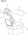
Fig. 2 eine rückwärtige perspektivische Darstellung des Fahrzeugsitzes gemäßFig. 1 , -
Fig. 3 eine zweite Ausführungsform die sich von dem ersten Ausführungsbeispiel unterscheidet indem die Projektionsvorrichtung zwei Projektionswände aufweist. - Das erfindungsgemäße Kopfstützensystem insgesamt ist in den Figuren mit dem Bezugszeichen 10 bezeichnet. Gleiche Bezugszeichen in den unterschiedlichen Figuren bezeichnen entsprechende Teile, auch wenn kleine Buchstaben hinzugefügt oder weggelassen sind.
- In
Fig. 1 ist ein Fahrzeugsitz 11 mit einem Sitzbereich 16, einer Rückenlehne 15 und einer Kopfstütze 12 dargestellt, welcher in einem Fahrzeuginnenraum 29 angeordnet ist. Die Kopfstütze 12 umfasst ein Kopfanlageteil 21 mit einer Anlagefläche 14 für den Kopf des Sitzinsassen. Die Rückenlehne 15 umfasst eine Anlagefläche 13. Der Fahrzeugsitz 11 ist mittels einer Befestigungsvorrichtung 17, z.B. mittels einer verstellbaren Schienenlagerung, an dem Fahrzeugboden 18 befestigt, der inFig. 1 lediglich angedeutet ist. - Die Kopfstütze 12 umfasst eine Projektorvorrichtung 26 mit Projektionseinheiten 19a und 19b, die im vorliegenden Ausführungsbeispiel jeweils einem sogenannten Beamer entsprechenund Lichtstrahlung übertragen. Alternativ könnten die Projektionseinheiten 19a und 19b auch eine andere Strahlung, wie z.B. Laserstrahlung, aussenden.
- Durch Projektionsöffnungen 20a und 20b in dem Kopfanlageteil 21, die in dem vorliegenden Ausführungsbeispiel an einem unteren Endbereich 27 des Kopfanlageteils 21 in Seitenbereichen angeordnet sind, können die Projektionseinheiten 19a und 19b, die in einem Innenraum des Kopfanlageteils 21 angeordnet sind, die Lichtinformation nach außen projezieren. Alternativ könnten die Projektionsöffnungen 20a und 20b auch an einem anderen Bereich des Kopfanlageteils 21 angeordnet sein, z.B. höher an den Seitenbereichen oder an einem oberen Endbereich 28. Anstelle der zwei Projektionseinheiten 20a und 20b könnte die Projektionsvorrichtung 26 z.B. auch lediglich eine Projektionseinheit aufweisen.
- Mit jeder Projektionseinheit 19a und 19b sind Lichtinformationen auf eine Projektionsfläche 22 einer Projektionswand 23 projezierbar. Die Projektionswand kann bei lediglich einfachen Lichtinformationen z.B. von dem Fahrzeugfenster, oder von der Armaturentafel gebildet sein. Bei detaillierteren Lichtinformationen, wie z.B. Bilddarstellungen, ist es vorteilhaft, wenn die Bildinformation auf einer speziell dafür bereitgestellten Fläche abgebildet werden.
- Alternativ wird z.B. von wenigstens einer der Projektionseinheiten 19a und 19b ein Hologramm z.B. durch Laserstrahlung erzeugt. In diesem Fall ist keine Projektionswand notwendig. Die Abbildung ist dann zweidimensional oder dreidimensional an beliebiger Position im Raum möglich.
- Die Projektionsfläche kann stationär in dem Fahrzeuginnenraum ausgebildet sein. Alternativ kann die Projektionsfläche 22 von einer Projektionswand 23 bereitgestellt werden, die im Falle einer Aktivierung der Projektionseinheit 19a und / oder 19b aus einer Stauposition in eine aufgespannte Position verstellt wird und die dann die Projektionsfläche 22 ausbildet.
- In dem Ausführungsbeispiel gemäß der
Fig. 1 und2 projezieren die beiden Projektionseinheiten 19a und 19b ihre Lichtinformation auf die Projektionsfläche 22. Gemäß einer alternativen Ausgestaltung der Erfindung projeziert die Projektionseinheit 19a ihre Lichtinformation auf eine erste Projektionsfläche 22 die Projektionseinheit 19b projeziert unabhängig von der ersten Projektionseinheit 19a eine Lichtinformation auf eine zweite Projektionsfläche 24 einer zweiten Projektionswand 25 (sieheFig. 3 ).
Claims (11)
- Kopfstütze (12) für einen Fahrzeugsitz (11) mit einem Kopfanlageteil (21) welches mittels einer Halterung an dem Fahrzeugsitz (11) lagerbar ist oder welches einstückig mit einem Teil des Fahrzeugsitzes (11) ausgebildet ist, dass das Kopfanlageteil (21) wenigstens eine Projektorvorrichtung (26) aufweist, welche wenigstens eine Projektionseinheit (19a, 19b) umfasst, die mit einer Stromversorgung des Fahrzeugs verbindbar ist, mittels welcher eine Strahlung, wie z.B. Lichtinformation oder Laserstrahlung auf einen Projektionsbereich projezierbar ist.
- Kopfstütze nach Anspruch 1, dadurch gekennzeichnet, dass die Projektionseinheit (19a, 19b) derart an dem Kopfanlageteil (21) ausrichtbar ist, dass die Lichtinformation auf eine Projektionsfläche (22, 24) des Fahrzeuginnenraums, wie Fenster, Armaturenbrett, Fahrzeugsitz, Fahrzeughimmel, auftrifft.
- Kopfstütze nach Anspruch 1, dadurch gekennzeichnet, dass die Projektionseinheit (19a, 19b) eine Strahlung überträgt, die im Fahrzeuginnenraum ein selbstleuchtendes Hologramm erzeugt.
- Kopfstütze nach einem der vorangehenden Ansprüche, dadurch gekennzeichnet, dass die Projektorvorrichtung (26) eine Steuerung umfasst, welche in Abhängigkeit eines empfangenen Signals einen Strahlungszustand, wie Konstantstrahlung, Intervallstrahlung, Farbe der Strahlung, steuert.
- Kopfstütze nach Anspruch 4, dadurch gekennzeichnet, dass die Projektorvorrichtung (26) wenigstens einen mit der Steuerung verbundenen Sensor umfasst, mittels welchem ein Signal an die Steuerung übermittelbar ist.
- Kopfstütze nach einem der vorangehenden Ansprüche, dadurch gekennzeichnet, dass die Projektorvorrichtung (26) mit einem Computer verbindbar ist und dass ein vom Computer erzeugtes Bild von der Projektionseinheit (19a, 19b) in dem Projektionsbereich (22, 24) abbildbar ist.
- Kopfstütze nach einem der vorangehenden Ansprüche, dadurch gekennzeichnet, dass die Steuerung zusätzlich manuell betätigbar ist.
- Kopfstützensystem (10) umfassend eine Kopfstütze (12) gemäß einem der vorangehenden Ansprüche sowie eine Projektionsfläche (22, 24) des Fahrzeuginnenraums.
- Kopfstützensystem nach Anspruch 8, dadurch gekennzeichnet, dass die Projektionsfläche (22, 24) einer Aufspannvorrichtung zugeordnet ist, mittels welcher die Projektionsfläche (22, 24) zwischen einer Stauposition und einer aufgespannten Position bewegbar ist.
- Kopfstützensystem nach einem der Ansprüche 8 oder 9, dadurch gekennzeichnet, dass jede Projektionseinheit (19a, 19b) einer separaten Projektionsfläche (22, 24) zugeordnet ist.
- Kopfstützensystem nach einem der Ansprüche 8 bis 10, dadurch gekennzeichnet, dass mehrere Projektionseinheiten (19a, 19b) einer Projektionsfläche (22) zugeordnet sind.
Applications Claiming Priority (1)
| Application Number | Priority Date | Filing Date | Title |
|---|---|---|---|
| DE102019000120.6A DE102019000120A1 (de) | 2019-01-11 | 2019-01-11 | Kopfstütze und Kopfstützensystem |
Publications (1)
| Publication Number | Publication Date |
|---|---|
| EP3680131A1 true EP3680131A1 (de) | 2020-07-15 |
Family
ID=69147531
Family Applications (1)
| Application Number | Title | Priority Date | Filing Date |
|---|---|---|---|
| EP20150688.8A Withdrawn EP3680131A1 (de) | 2019-01-11 | 2020-01-08 | Kopfstütze und kopfstützensystem |
Country Status (4)
| Country | Link |
|---|---|
| US (1) | US20200223341A1 (de) |
| EP (1) | EP3680131A1 (de) |
| CN (1) | CN111434525A (de) |
| DE (1) | DE102019000120A1 (de) |
Cited By (2)
| Publication number | Priority date | Publication date | Assignee | Title |
|---|---|---|---|---|
| EP3954577A1 (de) * | 2020-08-11 | 2022-02-16 | Grammer Ag | System für ein fahrzeug mit einem fahrzeugsitz und einem fahrzeugdach |
| DE102022118315A1 (de) | 2022-07-21 | 2024-02-01 | Bayerische Motoren Werke Aktiengesellschaft | Projektionseinrichtung an Bord eines Fahrzeugs, Fahrzeug und Verfahren |
Families Citing this family (3)
| Publication number | Priority date | Publication date | Assignee | Title |
|---|---|---|---|---|
| KR20210068702A (ko) * | 2019-12-02 | 2021-06-10 | 현대자동차주식회사 | 자동차용 시트의 홀로그램 스위치 시스템 |
| CN113060059A (zh) * | 2021-04-27 | 2021-07-02 | 项伟能 | 一种多功能新型汽车座椅 |
| DE102022202350B4 (de) | 2022-03-09 | 2024-03-07 | Volkswagen Aktiengesellschaft | Verfahren und Vorrichtung zur Visualisierung von Anweisungen zur Installation und korrekten Nutzung eines Kindersitzes |
Citations (11)
| Publication number | Priority date | Publication date | Assignee | Title |
|---|---|---|---|---|
| EP0891887A1 (de) * | 1997-07-17 | 1999-01-20 | Daimler-Benz Aktiengesellschaft | Verwendung eines holographischen Bildschirmes als Darstellungsfläche in einem Fahrzeug |
| US20020093565A1 (en) * | 1998-07-22 | 2002-07-18 | Watkins D. Scott | Headrest and seat video imaging apparatus |
| DE10226451C1 (de) * | 2002-06-13 | 2003-07-17 | Webasto Vehicle Sys Int Gmbh | Vorrichtung zum Darstellen von visuellen Informationen in Fahrzeugen |
| US20040046899A1 (en) * | 2002-09-05 | 2004-03-11 | Bonnett Craig Eugene | Vehicle interior projection entertainment system |
| DE102005002617A1 (de) * | 2005-01-20 | 2006-08-03 | Carl Zeiss Jena Gmbh | Anordnung zur Bildprojektion in einem Kraftfahrzeug |
| FR2960493A1 (fr) * | 2010-05-28 | 2011-12-02 | Peugeot Citroen Automobiles Sa | Appui-tete et dispositif de montage d'accessoires sur ledit appui -tete |
| EP2520453A1 (de) * | 2011-05-03 | 2012-11-07 | Peguform Gmbh | Vorrichtung zur Darstellung visueller Informationen in einem Kraftfahrzeug |
| EP2746833A1 (de) * | 2012-12-18 | 2014-06-25 | Volvo Car Corporation | Fahrzeuganpassung an einen automatischen fahrerunabhängigen Steuerungsmodus |
| EP2942774A1 (de) * | 2013-01-04 | 2015-11-11 | JVC Kenwood Corporation | Bildanzeigevorrichtung |
| EP3179717A1 (de) * | 2015-12-07 | 2017-06-14 | Funai Electric Co., Ltd. | Projektionsvorrichtung |
| US20170334451A1 (en) * | 2016-05-17 | 2017-11-23 | Honda Motor Co., Ltd. | Vehicle control system, vehicle control method, and medium storing vehicle control program |
Family Cites Families (8)
| Publication number | Priority date | Publication date | Assignee | Title |
|---|---|---|---|---|
| DE102006030194B4 (de) * | 2006-06-30 | 2015-07-02 | Airbus Operations Gmbh | Integrierter Projektor in einem Sitz zur optischen Anzeige von Informationen |
| EP1974980A1 (de) * | 2007-03-29 | 2008-10-01 | GM Global Technology Operations, Inc. | Kraftfahrzeuginformationssystem |
| JP5228716B2 (ja) * | 2007-10-04 | 2013-07-03 | 日産自動車株式会社 | 情報提示システム |
| DE102009008543B4 (de) * | 2009-02-11 | 2014-05-22 | Airbus Operations Gmbh | Innenraumprojektion für Luftfahrzeuge |
| US8733938B2 (en) * | 2012-03-07 | 2014-05-27 | GM Global Technology Operations LLC | Virtual convertible tops, sunroofs, and back windows, and systems and methods for providing same |
| JP2014231287A (ja) * | 2013-05-29 | 2014-12-11 | トヨタ紡織株式会社 | 乗物用シート |
| EP3162622B1 (de) * | 2014-06-27 | 2019-04-24 | Clarion Co., Ltd. | Akustische vorrichtung |
| US10214154B2 (en) * | 2016-09-22 | 2019-02-26 | Lear Corporation | Vehicle seat including a support for a video device |
-
2019
- 2019-01-11 DE DE102019000120.6A patent/DE102019000120A1/de not_active Ceased
-
2020
- 2020-01-08 EP EP20150688.8A patent/EP3680131A1/de not_active Withdrawn
- 2020-01-10 US US16/739,435 patent/US20200223341A1/en not_active Abandoned
- 2020-01-10 CN CN202010024085.2A patent/CN111434525A/zh active Pending
Patent Citations (11)
| Publication number | Priority date | Publication date | Assignee | Title |
|---|---|---|---|---|
| EP0891887A1 (de) * | 1997-07-17 | 1999-01-20 | Daimler-Benz Aktiengesellschaft | Verwendung eines holographischen Bildschirmes als Darstellungsfläche in einem Fahrzeug |
| US20020093565A1 (en) * | 1998-07-22 | 2002-07-18 | Watkins D. Scott | Headrest and seat video imaging apparatus |
| DE10226451C1 (de) * | 2002-06-13 | 2003-07-17 | Webasto Vehicle Sys Int Gmbh | Vorrichtung zum Darstellen von visuellen Informationen in Fahrzeugen |
| US20040046899A1 (en) * | 2002-09-05 | 2004-03-11 | Bonnett Craig Eugene | Vehicle interior projection entertainment system |
| DE102005002617A1 (de) * | 2005-01-20 | 2006-08-03 | Carl Zeiss Jena Gmbh | Anordnung zur Bildprojektion in einem Kraftfahrzeug |
| FR2960493A1 (fr) * | 2010-05-28 | 2011-12-02 | Peugeot Citroen Automobiles Sa | Appui-tete et dispositif de montage d'accessoires sur ledit appui -tete |
| EP2520453A1 (de) * | 2011-05-03 | 2012-11-07 | Peguform Gmbh | Vorrichtung zur Darstellung visueller Informationen in einem Kraftfahrzeug |
| EP2746833A1 (de) * | 2012-12-18 | 2014-06-25 | Volvo Car Corporation | Fahrzeuganpassung an einen automatischen fahrerunabhängigen Steuerungsmodus |
| EP2942774A1 (de) * | 2013-01-04 | 2015-11-11 | JVC Kenwood Corporation | Bildanzeigevorrichtung |
| EP3179717A1 (de) * | 2015-12-07 | 2017-06-14 | Funai Electric Co., Ltd. | Projektionsvorrichtung |
| US20170334451A1 (en) * | 2016-05-17 | 2017-11-23 | Honda Motor Co., Ltd. | Vehicle control system, vehicle control method, and medium storing vehicle control program |
Cited By (2)
| Publication number | Priority date | Publication date | Assignee | Title |
|---|---|---|---|---|
| EP3954577A1 (de) * | 2020-08-11 | 2022-02-16 | Grammer Ag | System für ein fahrzeug mit einem fahrzeugsitz und einem fahrzeugdach |
| DE102022118315A1 (de) | 2022-07-21 | 2024-02-01 | Bayerische Motoren Werke Aktiengesellschaft | Projektionseinrichtung an Bord eines Fahrzeugs, Fahrzeug und Verfahren |
Also Published As
| Publication number | Publication date |
|---|---|
| CN111434525A (zh) | 2020-07-21 |
| US20200223341A1 (en) | 2020-07-16 |
| DE102019000120A1 (de) | 2020-07-16 |
Similar Documents
| Publication | Publication Date | Title |
|---|---|---|
| EP3680131A1 (de) | Kopfstütze und kopfstützensystem | |
| DE102007005028B4 (de) | Verfahren und Vorrichtung zum Wiedergeben von Information auf einer Projektionsfläche in einem Fahrzeug | |
| EP3380363B1 (de) | Kraftfahrzeug mit innenraumbeleuchtungsvorrichtung(en) zum abstrahlen von lauflicht | |
| EP3108334B1 (de) | System mit und verfahren zum automatischen ein-/umschalten einer einstellvorrichtung für eine head-up-display-einrichtung | |
| EP3022089A1 (de) | Dynamische sichtfeldausleuchtung | |
| DE10131459A1 (de) | Video-Überwachungsanordnung für Kraftfahrzeuge | |
| DE102007053422A1 (de) | Recheneinrichtung | |
| DE19802220A1 (de) | Anzeigevorrichtung | |
| DE102013013227B4 (de) | Kraftwagen mit Anzeigeeinheit und Sicherung gegen eine Fahrerablenkung | |
| DE102016210088B3 (de) | Verfahren und Vorrichtung zur Darstellung einer Umgebung eines Kraftfahrzeugs | |
| DE102018220044A1 (de) | Äussere Anzeigebeleuchtungsvorrichtung eines Fahrzeugs | |
| DE102016007945A1 (de) | Vorrichtung zur Darstellung einer Projektion auf einer Projektionsfläche für ein Fahrzeug | |
| DE102018207618A1 (de) | Lichtemittierende Vorrichtung für Fahrzeuge | |
| DE60225219T2 (de) | Vorrichtung zur Insassenraumüberwachung | |
| DE102016217037B4 (de) | Verfahren zum Betreiben einer Anzeigeeinrichtung eines Kraftfahrzeugs mit einer digitalen Anzeigefläche und Kraftfahrzeug | |
| DE102020133448A1 (de) | Fahrzeug | |
| DE102020216295A1 (de) | Vorrichtung zur Vermeidung oder Reduzierung von Kinetose | |
| DE102016003021B4 (de) | Kraftfahrzeug-Steuervorrichtung und Verfahren zum Ermitteln einer Position eines in einem Kraftfahrzeug eingebauten optischen Sensors | |
| DE102018219106A1 (de) | Fahrzeugsteuerung | |
| DE102013019143B4 (de) | Kraftfahrzeug und Verfahren zur Erkennung der Lage und Position einer Anzeigevorrichtung in einem Fahrzeuginnenraum | |
| DE102015006655A1 (de) | Kraftfahrzeug mit mindestens einer Projektionseinrichtung | |
| DE102015212288B3 (de) | Verfahren zur Darstellung von Kamerabildinhalten in einem Fahrzeug | |
| DE102014220524A1 (de) | Vorrichtung zur Unterstützung eines Fahrers eines Fahrzeugs und Fahrzeug | |
| DE102020211268B4 (de) | Aussenspiegelanordnung mit umfeldleuchte und verfahren zur beleuchtung | |
| DE102009006927B4 (de) | Vorrichtung und Verfahren zur Steuerung der Beleuchtung von Anzeige- und/oder Bedienelementen |
Legal Events
| Date | Code | Title | Description |
|---|---|---|---|
| PUAI | Public reference made under article 153(3) epc to a published international application that has entered the european phase |
Free format text: ORIGINAL CODE: 0009012 |
|
| STAA | Information on the status of an ep patent application or granted ep patent |
Free format text: STATUS: THE APPLICATION HAS BEEN PUBLISHED |
|
| AK | Designated contracting states |
Kind code of ref document: A1 Designated state(s): AL AT BE BG CH CY CZ DE DK EE ES FI FR GB GR HR HU IE IS IT LI LT LU LV MC MK MT NL NO PL PT RO RS SE SI SK SM TR |
|
| AX | Request for extension of the european patent |
Extension state: BA ME |
|
| RAP1 | Party data changed (applicant data changed or rights of an application transferred) |
Owner name: GRAMMER AG |
|
| STAA | Information on the status of an ep patent application or granted ep patent |
Free format text: STATUS: THE APPLICATION IS DEEMED TO BE WITHDRAWN |
|
| 18D | Application deemed to be withdrawn |
Effective date: 20210116 |