EP3679439B1 - Verfahren und unbemanntes luftfahrzeug zur erfassung von daten bezüglich einer windturbine - Google Patents
Verfahren und unbemanntes luftfahrzeug zur erfassung von daten bezüglich einer windturbine Download PDFInfo
- Publication number
- EP3679439B1 EP3679439B1 EP18762324.4A EP18762324A EP3679439B1 EP 3679439 B1 EP3679439 B1 EP 3679439B1 EP 18762324 A EP18762324 A EP 18762324A EP 3679439 B1 EP3679439 B1 EP 3679439B1
- Authority
- EP
- European Patent Office
- Prior art keywords
- sensor
- uav
- distance
- blade
- flight path
- Prior art date
- Legal status (The legal status is an assumption and is not a legal conclusion. Google has not performed a legal analysis and makes no representation as to the accuracy of the status listed.)
- Active
Links
Images


Classifications
-
- G—PHYSICS
- G05—CONTROLLING; REGULATING
- G05D—SYSTEMS FOR CONTROLLING OR REGULATING NON-ELECTRIC VARIABLES
- G05D1/00—Control of position, course, altitude or attitude of land, water, air or space vehicles, e.g. using automatic pilots
- G05D1/0094—Control of position, course, altitude or attitude of land, water, air or space vehicles, e.g. using automatic pilots involving pointing a payload, e.g. camera, weapon, sensor, towards a fixed or moving target
-
- F—MECHANICAL ENGINEERING; LIGHTING; HEATING; WEAPONS; BLASTING
- F03—MACHINES OR ENGINES FOR LIQUIDS; WIND, SPRING, OR WEIGHT MOTORS; PRODUCING MECHANICAL POWER OR A REACTIVE PROPULSIVE THRUST, NOT OTHERWISE PROVIDED FOR
- F03D—WIND MOTORS
- F03D17/00—Monitoring or testing of wind motors, e.g. diagnostics
-
- G—PHYSICS
- G01—MEASURING; TESTING
- G01C—MEASURING DISTANCES, LEVELS OR BEARINGS; SURVEYING; NAVIGATION; GYROSCOPIC INSTRUMENTS; PHOTOGRAMMETRY OR VIDEOGRAMMETRY
- G01C11/00—Photogrammetry or videogrammetry, e.g. stereogrammetry; Photographic surveying
-
- G—PHYSICS
- G01—MEASURING; TESTING
- G01M—TESTING STATIC OR DYNAMIC BALANCE OF MACHINES OR STRUCTURES; TESTING OF STRUCTURES OR APPARATUS, NOT OTHERWISE PROVIDED FOR
- G01M11/00—Testing of optical apparatus; Testing structures by optical methods not otherwise provided for
- G01M11/08—Testing mechanical properties
- G01M11/081—Testing mechanical properties by using a contact-less detection method, i.e. with a camera
-
- G—PHYSICS
- G01—MEASURING; TESTING
- G01M—TESTING STATIC OR DYNAMIC BALANCE OF MACHINES OR STRUCTURES; TESTING OF STRUCTURES OR APPARATUS, NOT OTHERWISE PROVIDED FOR
- G01M5/00—Investigating the elasticity of structures, e.g. deflection of bridges or air-craft wings
- G01M5/0016—Investigating the elasticity of structures, e.g. deflection of bridges or air-craft wings of aircraft wings or blades
-
- G—PHYSICS
- G01—MEASURING; TESTING
- G01M—TESTING STATIC OR DYNAMIC BALANCE OF MACHINES OR STRUCTURES; TESTING OF STRUCTURES OR APPARATUS, NOT OTHERWISE PROVIDED FOR
- G01M5/00—Investigating the elasticity of structures, e.g. deflection of bridges or air-craft wings
- G01M5/0075—Investigating the elasticity of structures, e.g. deflection of bridges or air-craft wings by means of external apparatus, e.g. test benches or portable test systems
-
- B—PERFORMING OPERATIONS; TRANSPORTING
- B64—AIRCRAFT; AVIATION; COSMONAUTICS
- B64U—UNMANNED AERIAL VEHICLES [UAV]; EQUIPMENT THEREFOR
- B64U10/00—Type of UAV
- B64U10/10—Rotorcrafts
- B64U10/13—Flying platforms
-
- B—PERFORMING OPERATIONS; TRANSPORTING
- B64—AIRCRAFT; AVIATION; COSMONAUTICS
- B64U—UNMANNED AERIAL VEHICLES [UAV]; EQUIPMENT THEREFOR
- B64U2101/00—UAVs specially adapted for particular uses or applications
- B64U2101/30—UAVs specially adapted for particular uses or applications for imaging, photography or videography
-
- B—PERFORMING OPERATIONS; TRANSPORTING
- B64—AIRCRAFT; AVIATION; COSMONAUTICS
- B64U—UNMANNED AERIAL VEHICLES [UAV]; EQUIPMENT THEREFOR
- B64U2201/00—UAVs characterised by their flight controls
- B64U2201/10—UAVs characterised by their flight controls autonomous, i.e. by navigating independently from ground or air stations, e.g. by using inertial navigation systems [INS]
Definitions
- Turbine blades typically are made of fibre-reinforced composites, with resins such as polyester and epoxy, and with glass and carbon fibers as the reinforcing material. Defects of the blades can be caused by the impact of objects, lightning, erosion by rain and hail, mechanical stress and flexing, aging, etc. Owners and operators should obtain full transparency with respect to the health of their assets. The detailed knowledge about defects and their propagation over time is the most important prerequisite for preventive maintenance and repair, which are known to unlock great cost savings. In addition, it facilitates compliance with legislation and with requirements by insurance companies. For this reason, rotor blades and wind-turbine towers have to be inspected periodically.
- inspection sensors such as a camera
- sensors for navigation and which defines positions of the UAV at which sensor readings (such as images) are to be taken, and/or areas or points to be inspected or photographed.
- the sensor data can in particular be image data.
- the sensor metadata can in particular comprise sensor pose data. Pose data describes the pose of an object in 3D space, that is the combination of its position and orientation. Further sensor metadata can describe parameters of the inspection sensor related to the captured sensor data. For example, if the sensor is a camera, the sensor metadata can be exposure time, focus settings, etc.
- storing each set of sensor data in association with sensor pose data comprises the steps of, during an inspection mission:
- the reference flight path can be in terms of the trajectory and pose of the UAV or the trajectory and pose of the inspection sensor. The two are related by their relative position and the gimbal angles.
- the data from the distance sensor comprises an actual distance map comprising distance measurements at least in a plane intersecting the turbine, and the method comprises the steps of
- the correct actual pose of the distance sensor and of the UAV typically gives rise to a correction in the actual flight path.
- the blade is arranged with its tip in its lowermost position, closest to the ground.
- the standard configuration can be with the rotor at other angles, e.g. with the blade pointing up or being horizontal.
- the actual distance map comprises, in a horizontal plane, at least one of a distance from the distance sensor to the tower and a distance from the distance sensor to the blade, in particular in each case the minimum distance.
- the actual position of the distance sensor (or, equivalently, of the UAV) in the plane can be computed by triangulation.
- the actual position in the plane is used to correct the position within the computer model. If only one can be measured, then the actual position can be corrected at least in the direction of the measurement.
- the actual turbine is arranged to be in the standard configuration for inspection.
- the parameters define at least a root height, span and chord length of the blade, and optionally also a diameter of the tower and a (shortest) distance between the tower and the blade, an angle of the blade relative to the vertical, a pitch angle of the blade, and the nacelle angle.
- the height of the root of the blade above ground level can be determined by giving a height of the tip above ground and adding the span.
- the parameterised model is for a turbine in the standard configuration for inspection.
- the reference flight path comprises data defining at least one of a reference trajectory for the UAV and a reference trajectory for the inspection sensor, and reference data defining the orientation of the inspection sensor
- the reference flight path comprises an initialisation section with a plausibility check
- the method comprises the steps of:
- the UAV might approach the turbine from (seen from the front) e.g. the left side instead of the right side as desired. This would cause the distance sensor to observe, when scanning from left to right, first the tower, then an empty space (quasi infinite distance) and then the blade. However, the expectation is to observe first the blade, then empty space, then the tower. In the event of a mismatch, the mission can be aborted, before the UAV continues to operate under false initial conditions. Other errors that can be detected in this way are an incorrect horizontal orientation or location, which would, for example, cause the blade to be hidden behind the tower or cause the two to overlap.
- the tower can be identified in the distance measurements by having a round contour, the blade by being flat or curved along its chord lines. In the standard configuration for inspection the chord lines lie essentially in horizontal planes.
- the reference flight path comprises a height calibration section
- the method comprises the steps of:
- the height of the UAV is corrected at other points as the UAV follows its flight path. This can be done based on the actual distance map, when other features of the blade and/or tower are observed, in particular features that cause discontinuities in the actual distance map and are located at a height that is represented in the model. For example, this can be the root of the blade.
- other sensors and related features can be used, such as the inspection sensor. For example, if the inspection sensor is a camera, markings or deviations that are at a known location on the blade can be used, together with information about the pose of the inspection sensor relative to the reference frame of the UAV, to correct its position.
- the actual flight path is derived from the reference flight path by the steps of, repeatedly at points in time following each other:
- the UAV can, for example, follow the reference flight path with regard to vertical position and with regard to its orientation, but maintain the desired reference position with regard to horizontal position, in accordance with horizontal position measurements by the distance sensor.
- the actual flight path can be determined by means of known optimisation procedures or control methods, such as a Kalman filter, Model Predictive Control (MPC), in particular Predictive Functional Control (PFC) methods etc.
- MPC Model Predictive Control
- PFC Predictive Functional Control
- the flight controller can modify the flight path to limit acceleration of the UAV to values that can be physically realised.
- the reference and the measured relative position are one of
- deviations can be determined in accordance to the type of sensors that are available. If a 3D scanner can observe at least part of the turbine, its measurements can be used to determine the deviation.
- this measurement plane typically lies at least approximately normal to the flight path, or to a section of the flight path in which this correction of the flight path is active.
- this measurement plane is horizontal.
- This method can be applied in general to the inspection of objects other than blades of turbines. Then the reference relative position is defined in relation to such an object to be inspected.
- the method comprises the step of:
- the method comprises the step of:
- the lens position can be set and controlled quickly by a mechanical drive turning the focusing ring, in accordance with the desired focus setting.
- this is an open loop control arrangement, with the distance as input and the focus setting as output. Nevertheless, there can there can be a local, closed control loop for turning the focusing ring to a set point. This arrangement allows to control the focus faster and in a more precise manner than with through-the-lens optical autofocusing.
- the method comprises the steps of:
- the point of focus is a point of interest that should be in focus when capturing an image. This can be a point on a particular line along the blade, such as a seam line or one of the edges. It can also be a location at which a deviation is expected to be, e.g. based on information from a previous inspection mission.
- the distance sensor does not provide a distance to the point of focus, the distance can be extracted from the computer model of the blade and the pose of the UAV or the inspection sensor. The accuracy of this distance can be increased by determining the relative position of the inspection sensor or camera to the blade by means of the distance sensor. This relative position can be a position in 3D space, or in two dimensions in a plane, or just one distance measurement. Depending on which it is, the relative position maintained in the computer model can be corrected in one or more dimensions.
- the unmanned aerial vehicle for acquiring sensor data related to a wind turbine is programmed to perform one or more of the method steps described herein.
- a computer program for acquiring sensor data related to a wind turbine is loadable into an internal memory of a digital computer or a computer system controlling the UAV, and comprises computer-executable instructions to cause one or more processors of UAV to execute method steps presented herein.
- a computer program product comprises a computer readable medium having the computer-executable instructions recorded thereon.
- the computer readable medium preferably is non-transitory; that is, tangible.
- the computer program is embodied as a reproducible computer-readable signal, and thus can be transmitted in the form of such a signal.
- the executing of the method can involve the computer program interacting with a user, by means of output devices such as a display, printer, etc. and input devices such as a keyboard, pointing device, touchscreen, etc.
- FIG. 1 schematically shows a wind turbine 10 comprising a tower 1 supporting a nacelle enclosing a drive train driving an electrical generator via a gearbox.
- Turbine blades 3 are arranged on a hub to form a rotor 2 driving the drive train.
- Each blade 3 is typically secured at its root end 32, and then “spans" radially Each blade 3 is typically secured at its root end 32, and then “spans” radially “outboard” to a free end or tip 31.
- the distance from the tip 31 to the root 32, at the opposite end of the blade 3, is called the “span.”
- the front, or leading edge 33 of the blade 3 connects the forward-most points of the blade 3 that first contact the air.
- the rear, or trailing edge 34 of the blade 3 is where airflow that has been separated by the leading edge 33 rejoins after passing over a suction surface or side 35 and a pressure surface or side 36 of the blade.
- chord line connects the leading and trailing edges of the blade 3 in the direction of the typical airflow across the blade.
- the length of the chord line is called the chord Since many blades 10 change their chord over the span, the chord length is referred to as the "root chord,” near the root, and the “tip chord,” near the tip of the blade.
- the chord lines are arranged in the “chord planes” that extend through the streamlines on the corresponding pressure and suction surfaces of the blade.
- Figure 1 also shows a reference flight path 54a.
- the reference flight path 54a can be generated from a generic flight path 53 by scaling it according to the actual dimensions, expressed by a set of parameters, of the turbine 10 to be inspected.
- the parameters can comprise
- the flight path shows a first section 531 in which the UAV 4 flies to a height at which both the tower 1 and blade 3 are expected to be visible in a horizontal scan by the distance sensor 44. If they are indeed visible, and in the right relative arrangement, the inspection proceeds along the flight path.
- a second section, 532 the UAV 4 slowly descends, continuously scanning at least the blade 3 with the distance sensor 44, with an at least approximately horizontal scanning plane 48, until the blade 3 is no longer detected. This means that the UAV 4 has moved past the tip 31, and the height of the UAV 4 above ground or relative to the turbine 10 can be calibrated.
- the height of the tip 31 relative to the UAV 4 can be located by the distance sensor 44 more precisely by moving the UAV 4 up or down, or by controlling the pitch of the gimbal 41, thereby rotating the measurement plane or scanning plane 48 of the distance sensor 44.
- the flight path shows several sections 533 along which the UAV 4 moves along the span of the blade 3 on vertical paths, upward or downward. Each such vertical section covers the span of the blade 3, and thus images taken along one section cover one circumferential section of the blade.
- the vertical sections are arranged around the blade 3, and so the images 6 from all vertical sections together can provide a complete view of the surface of the blade 3.
- FIG 2 schematically shows an unmanned aerial vehicle (UAV) 4, such as a multicopter, as it can be used in embodiments of the invention.
- UAV unmanned aerial vehicle
- It carries an inspection sensor 42 suspended by gimbal 41, rotatable about at least two or three Euler angles.
- the inspection sensor 42 typically is an optical camera and shall henceforth be referred to as such. However, other types of inspection sensors can be envisioned, such as devices operating in the non-optical ranges of the electromagnetic spectrum, range sensors etc.
- the camera 42 comprises a focus drive 43 for changing a focus setting of the camera lens.
- a 2D depth map comprises 3D information in that it comprises a 2D array of data, wherein the data indicates the distance from a point (such as a sensor) or in general also from a plane.
- the UAV 4 comprises a GPS 45 module and/or a further sensor 46, such as inertial sensor, gyroscope, barometer and/or compass.
- a flight controller 47 is arranged to integrate data from the GPS 45 and/or further sensor 46 and the distance sensor 44, and a computer model of an object to be inspected, such as a wind turbine 10, and to generate flight commands such as position or speed vectors to be executed by the UAV 4. This can be done by, at a given time and location, determining the pose of the UAV 4, comparing it to the pose according to the reference path, and calculating flight commands based on current pose, velocity and acceleration information to move the UAV to a next pose along the reference path at a future point in time.
- the reference path and the next pose typically includes reference speed vectors.
- Figure 3 illustrates a method for correcting the pose of the distance sensor 44 within the computer model.
- the figure shows a section through the tower 1 and the blade 3 to be inspected, the section plane being the scanning plane 48 of the distance sensor 44 at its current pose. Typically the scanning plane 48 is horizontal, but it can also be tilted, and this can be taken into account when computing the section.
- the solid lines show where, within the computer model, the tower 1 and the blade 3 are located in relation to the distance sensor. These are their expected positions, and constitute a reference distance map 56a as seen from the distance sensor at its modelled position 44a relative to the tower 1 and blade 3. Actual measurements from the distance sensor 44 constitute an actual distance map 56b, indicated by crosses, in their relation to the position of the distance sensor 44.
- the actual distance map 56b can be matched with the reference distance map 56a and the sensor position corrected accordingly. For example, given the actual distance map 56b comprising a multitude of measurement points (i.e. the crosses), this set of measurement points can be translated and rotated to best match the part of the reference distance map 56a that is visible to the distance sensor 44. Translating and rotating the pose of the distance sensor 44 in the same way gives the corrected position 44b of the distance sensor 44.
- the reference and actual distance maps comprise only the distances from the distance sensor 44 to closest points on the tower 1 and the blade 3, as reference distances 55a and actual distances 55b, respectively. These distances can be used to triangulate the corrected position 44b of the distance sensor 44 relative to the tower land blade 3.
- the blade 3 since the single distance measurements provide limited information, it is advantageous to have the blade 3 arranged with its tip 31 in its lowermost position, closest to the ground, i.e. in the standard configuration for inspection. This allows the distance sensor 44 to measure the distance to both the blade 3 and the tower 1 in horizontal sweep, from which distances the corrected position can be triangulated.
- the distance maps and positions shown in Figure 3 are located within a plane that coincides with the plane in which the measurements of the distance sensor 44 take place, i.e. the measurement or scanning plane 48.
- This plane is generally normal to the direction of flight of the UAV 4, and typically horizontal where the UAV 4 moves in a vertical direction.
- the reference distance map 56a can be updated and adapted to the pose of the UAV 4 and the distance sensor 44, by determining the orientation of the scanning plane 48, and computing, in the computer model, the intersection of this plane with the modelled tower 1 and blade 3.
- Figure 4 illustrates a method for deriving the actual flight path 54b from the reference flight path 54a.
- a reference relative position of the UAV 4 in relation to the blade 3 in this example is the distance between the UAV 4 and a curve on the blade 3.
- This curve can be the leading edge 33 of the blade 3, as shown in the example, or another edge, or the line on the surface of the blade 3 that is closest to the UAV 4, etc.
- the expected trajectory of this curve is denoted by 33a.
- This expected curve is either "explicit", that is, it is part of a computer model of the blade and can be derived from the computer model.
- the expected curve can be "implicit" in the reference flight path 54a, that is, if the UAV 4 follows the reference flight path 54a, it is expected to be at a constant distance from the expected curve. In both cases, it can happen that the actual curve deviates from the expected one.
- the UAV 4 determines a measured relative position of the UAV 4 in relation to the blade 3 and corrects its trajectory such that it follows a given reference relative position of the UAV 4 in relation to the blade 3.
- the reference relative position can be a position and/or time dependent function, and/or it can specify the relative position in two dimensions relative to the blade 3, in particular a cross section of the blade 3.
- the reference relative position is just a distance, in particular a constant distance. This is illustrated in Figure 4 by a reference distance dr that should be maintained between the actual flight path 54b and the curve, with expected trajectory 33a.
- a naive autofocussing method would focus on the centre of the image, along the line of sight of the camera (indicated by an arrow). This would potentially yield a sensor reading which is not optimally focussed on the target of inspection (e.g., a blurred image ).
- the image data 72 can use ca. 12 GB of computer storage.
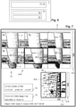
- Figure 7 shows the sequence of images 6 presented on a display device 8, arranged in a grid 610, with rows comprising images 6a, 6c taken at essentially the same height (along the span of the blade 3, assuming that the blade 3 is in a vertical position, pointing downward). Columns comprise images 6a, 6b of the same vertical section of the blade 3. In embodiments, there are one or more rows, and one or more columns.
- a vertical grid scroll element 611 is configured to, according to user input, scroll the one or more columns of the grid 610 vertically. In the Figure, the vertical scroll position is such that the lowermost row, showing the tip from different angles, is only partly displayed.
- a horizontal scroll element (not shown in the figure) can be present as well.
- the images 6a, 6b, 6c show the blade 3 in front of a landscape, and on some images a deviation 69 being a defect is visible.
- the deviations 69 or defects seen in the three images in the middle row all correspond to the same physical defect.
- the dark region corresponds to a patch created when the blade 3 was repaired.
Landscapes
- Engineering & Computer Science (AREA)
- Physics & Mathematics (AREA)
- General Physics & Mathematics (AREA)
- Aviation & Aerospace Engineering (AREA)
- Remote Sensing (AREA)
- Chemical & Material Sciences (AREA)
- Radar, Positioning & Navigation (AREA)
- Combustion & Propulsion (AREA)
- Mechanical Engineering (AREA)
- General Engineering & Computer Science (AREA)
- Multimedia (AREA)
- Sustainable Energy (AREA)
- Life Sciences & Earth Sciences (AREA)
- Sustainable Development (AREA)
- Analytical Chemistry (AREA)
- Automation & Control Theory (AREA)
- Control Of Position, Course, Altitude, Or Attitude Of Moving Bodies (AREA)
Claims (15)
- Verfahren zur Erfassung von Sensordaten bezüglich einer Windturbine unter Verwendung eines unbemannten Luftfahrzeugs (unmanned aerial vehicle - UAV) (4), das mindestens einen Inspektionssensor (42) zum Erfassen der Sensordaten (71) umfasst, wobei das Verfahren die folgenden Schritte umfasst:• Bestimmen eines Referenzflugpfads (54a) für das UAV (4) ;• Betreiben des UAV (4) dazu, automatisch entlang eines tatsächlichen Flugpfads (54b) zu fliegen, der von dem Referenzflugpfad (54a) abgeleitet ist,• Erfassen von mehreren Sätzen von Sensordaten (71) mit dem Inspektionssensor (42), während das UAV (4) entlang eines oder mehrerer Abschnitte des tatsächlichen Flugpfads (54b) fliegt,dadurch gekennzeichnet, dass das Verfahren die folgenden Schritte umfasst:• Speichern jedes Satzes von Sensordaten (71) in Zusammenhang mit Sensorstellungsdaten (74), die die Stellung des Inspektionssensors (42) zu jenem Zeitpunkt, zu dem der Satz von Sensordaten (71) erfasst wurde, definiert; und dadurch, dass zum Betreiben des UAV (4) dazu, automatisch entlang eines tatsächlichen Flugpfads (54b) zu fliegen, der folgende Schritt durchgeführt wird:• Bestimmen von mindestens einer der Stellung des UAV (4) und der Stellung des Inspektionssensors (42) durch Integrieren von Daten von mindestens einem von einem Satellitennavigationssystem (45) und einem Trägheitsnavigationssystem (46) mit Daten von einem Entfernungssensor (44), der sich an dem UAV (4) befindet, und einem Computermodell von mindestens einem Teil der Turbine (10).
- Verfahren nach Anspruch 1, wobei die Daten von dem Entfernungssensor (44) eine Karte (56b) einer tatsächlichen Entfernung umfassen, die Entfernungsmessungen mindestens in einer Ebene umfasst, die die Turbine (10) schneidet, und das die folgenden Schritte umfasst:• Bestimmen, aus dem Computermodell, einer Referenzentfernungskarte (56a), die Entfernungen von dem Entfernungssensor (44) zu mindestens einem des Turms (1) und der Schaufel (3) umfasst, gemäß der Stellung des Entfernungssensors (44) innerhalb des Computermodells;• Korrigieren der Stellung des Entfernungssensors (44) innerhalb des Computermodells gemäß einer geometrischen Transformation, die die Karte (56b) der tatsächlichen Entfernung mit der Referenzentfernungskarte (56a) abgleicht.
- Verfahren nach Anspruch 2, wobei die Schaufel (3) mit ihrer Spitze (31) in ihrer untersten Position, am nächsten an dem Boden, angeordnet ist.
- Verfahren nach Anspruch 3, wobei die Karte (56b) der tatsächlichen Entfernung in einer horizontalen Ebene mindestens einer von einer Entfernung von dem Entfernungssensor (44) zu dem Turm (1) und einer Entfernung von dem Entfernungssensor (44) zu der Schaufel (3), insbesondere in jedem Fall die Mindestentfernung, umfasst.
- Verfahren nach einem der vorhergehenden Ansprüche, das den folgenden Schritt umfasst:• Bestimmen des Referenzflugpfads (54a) durch Abrufen eines parametrierten generischen Flugpfads (53) und Einstellen seiner Parameter auf Parameter einer tatsächlichen Turbine, die inspiziert werden soll.
- Verfahren nach Anspruch 5, wobei die Parameter mindestens eine Fußhöhe, eine Spannweite und eine Sehnenlänge der Schaufel (3) und wahlweise ebenfalls einen Durchmesser des Turms (1) und eine Entfernung zwischen dem Turm (1) und der Schaufel (3) und wahlweise eines oder mehrere von einem Winkel der Schaufel relativ zu der Vertikalen, einem Neigungswinkel der Schaufel und einem Gondelwinkel definieren.
- Verfahren nach einem der vorhergehenden Ansprüche, wobei der Referenzflugpfad (54a) Daten, die mindestens eine von einer Referenzbewegungsbahn für das UAV (4) und einer Referenzbewegungsbahn für den Inspektionssensor (42) definieren, und Referenzdaten umfasst, die die Ausrichtung des Inspektionssensors (42) definieren.
- Verfahren nach einem der vorhergehenden Ansprüche, wobei der Referenzflugpfad (54a) einen Initialisierungsabschnitt mit einer Wahrscheinlichkeitsprüfung umfasst, wobei das Verfahren die folgenden Schritte umfasst:• Fliegen des UAV (4) auf eine Höhe über der Höhe der Spitze (31);• Bestimmen einer Karte (56b) der tatsächlichen Entfernungen mit einem Entfernungssensor (44), die Entfernungsmessungen mindestens in einer Ebene umfasst, die die Turbine (10) schneidet;• Verifizieren, ob ein Abschnitt der Karte (56b) der tatsächlichen Entfernung mit der Schaufel (3) abgeglichen werden kann und ein anderer, getrennter Abschnitts der Karte (56b) der tatsächlichen Entfernung mit dem Turm (1) abgeglichen werden kann und dass die relative Anordnung dieser zwei Abschnitte wie erwartet ist.
- Verfahren nach einem der vorhergehenden Ansprüche, wobei der Referenzflugpfad (54a) einen Höhenkalibrierungsabschnitt umfasst, wobei das Verfahren die folgenden Schritte umfasst:• Fliegen des UAV (4) auf eine Höhe über der Höhe der Spitze (31);• Bestimmen einer Karte (56b) der tatsächlichen Entfernung mit einem Entfernungssensor (44), die Entfernungsmessungen mindestens in einer Ebene umfasst, die mindestens die Schaufel (3) schneidet;• Verifizieren, ob ein Abschnitt der Karte (56b) der tatsächlichen Entfernung mit der Schaufel (3) abgeglichen werden kann;• Steuern des UAV (4), um seine Höhe zu reduzieren, unter fortlaufendem Wiederholen der Schritte des Bestimmens der Karte (56b) der tatsächlichen Entfernung und Verifizieren der Anwesenheit der Schaufel (3), bis die Schaufel (3) nicht länger detektiert ist, was angibt, dass sich das UAV (4) in Wirklichkeit an der Höhe der Spitze (31) befindet;• Korrigieren einer modellierten Höhe des UAV (4) innerhalb eines Computermodells, das eine Stellung des UAV (4) umfasst, um der Höhe der Spitze (31) zu entsprechen.
- Verfahren nach einem der Ansprüche 1 bis 9, wobei der tatsächliche Flugpfad (54b) von dem Referenzflugpfad (54a) durch die folgenden Schritte wiederholt zu Zeitpunkten nacheinander abgeleitet wird:• Eingeben des Referenzflugpfads (54a), einer relativen Referenzposition des UAV (4) in Bezug auf die Schaufel (3) und einer gemessenen relativen Position des UAV (4) in Bezug auf die Schaufel (3),• Bestimmen des tatsächlichen Flugpfads (54b) als eine Abweichung von dem Referenzflugpfad (54a), der einen Unterschied zwischen der Referenz und der gemessenen relativen Position des UAV (4) in Bezug auf die Schaufel (3) reduziert oder entfernt.
- Verfahren nach Anspruch 10, wobei die Referenz und die gemessene relative Position eines der Folgenden sind:• eine relative Position im 3D-Raum;• eine relative Position in einer Ebene, die in den zwei Dimensionen definiert ist, die durch die Ebene überspannt sind;• eine Entfernung, wie etwa eine Entfernung zu dem nächsten Punkt der Schaufel (3) oder zu einem ausgeprägten Punkt der Schaufel (3), wie etwa der Vorderkante (33) oder der Hinterkante (34).
- Verfahren nach einem der vorhergehenden Ansprüche, das den folgenden Schritt umfasst:• Steuern einer Ausrichtung des Inspektionssensors (42), um sein Sichtfeld auf einen Abschnitt der Schaufel (3), der inspiziert wird, zu konzentrieren, insbesondere durch Steuern einer horizontalen Ausrichtung (Gierung) des Inspektionssensors (42) .
- Verfahren nach einem der vorhergehenden Ansprüche, das den folgenden Schritt umfasst:• Steuern einer Fokuseinstellung des Inspektionssensors (42) gemäß einer Entfernungsmessung, die durch den Entfernungssensor (44) durchgeführt wird.
- Verfahren nach Anspruch 13, das die folgenden Schritte umfasst:• Bestimmen einer relativen Position des Inspektionssensors (42) zu der Schaufel (3) mittels des Entfernungssensors (44);• aus dieser relativen Position und aus einem Computermodell der Schaufel (3), Bestimmen, für einen Punkt des Fokus (63) an der Schaufel (3), der Entfernung dieses Punkt des Fokus (63) zu dem Inspektionssensor (42);• Steuern einer Fokuseinstellung des Inspektionssensors (42), um der Entfernung dieses Punkts des Fokus (63) zu entsprechen.
- Unbemanntes Luftfahrzeug (UAV) (4) zur Erfassung von Sensordaten bezüglich einer Windturbine, das mindestens einen Inspektionssensor (42) zur Erfassung der Sensordaten (71) umfasst, wobei das UAV (4) dazu programmiert ist, die folgenden Schritte durchzuführen:• Bestimmen eines Referenzflugpfads (54a) für das UAV (4) ;• Betreiben des UAV (4) dazu, automatisch entlang eines tatsächlichen Flugpfads (54b) zu fliegen, der von dem Referenzflugpfad (54a) abgeleitet ist,• Erfassen von mehreren Sätzen von Sensordaten (71) mit dem Inspektionssensor (42), während das UAV (4) entlang eines oder mehrerer Abschnitte des tatsächlichen Flugpfads (54b) fliegt,dadurch gekennzeichnet, dass das UAV (4) dazu programmiert ist, die folgenden Schritte durchzuführen:• Speichern jedes Satzes von Sensordaten (71) in Zusammenhang mit den Sensorstellungsdaten (74), die die Stellung des Inspektionssensors (42) zu dem Zeitpunkt definieren, zu dem der Satz von Sensordaten (71) erfasst wurde; undzum Betreiben des UAV (4) dazu, automatisch entlang eines tatsächlichen Flugpfads (54b) zu fliegen, den folgenden Schritt durchzuführen:• Bestimmen von mindestens einer der Stellung des UAV (4) und der Stellung des Inspektionssensors (42) durch Integrieren von Daten von mindestens einem von einem Satellitennavigationssystem (45) und einem Trägheitsnavigationssystem (46) mit Daten von einem Entfernungssensor (44), der sich an dem UAV (4) befindet, und einem Computermodell mindestens eines Teils der Turbine (10).
Applications Claiming Priority (2)
| Application Number | Priority Date | Filing Date | Title |
|---|---|---|---|
| EP17190207.5A EP3454157A1 (de) | 2017-09-08 | 2017-09-08 | Verfahren und unbemanntes luftfahrzeug zur erfassung von daten bezüglich einer windturbine |
| PCT/EP2018/074104 WO2019048596A1 (en) | 2017-09-08 | 2018-09-07 | METHOD AND AIR VEHICLE WITHOUT PILOT FOR ACQUIRING SENSOR DATA ASSOCIATED WITH A WIND TURBINE |
Publications (2)
| Publication Number | Publication Date |
|---|---|
| EP3679439A1 EP3679439A1 (de) | 2020-07-15 |
| EP3679439B1 true EP3679439B1 (de) | 2022-03-16 |
Family
ID=59923234
Family Applications (2)
| Application Number | Title | Priority Date | Filing Date |
|---|---|---|---|
| EP17190207.5A Withdrawn EP3454157A1 (de) | 2017-09-08 | 2017-09-08 | Verfahren und unbemanntes luftfahrzeug zur erfassung von daten bezüglich einer windturbine |
| EP18762324.4A Active EP3679439B1 (de) | 2017-09-08 | 2018-09-07 | Verfahren und unbemanntes luftfahrzeug zur erfassung von daten bezüglich einer windturbine |
Family Applications Before (1)
| Application Number | Title | Priority Date | Filing Date |
|---|---|---|---|
| EP17190207.5A Withdrawn EP3454157A1 (de) | 2017-09-08 | 2017-09-08 | Verfahren und unbemanntes luftfahrzeug zur erfassung von daten bezüglich einer windturbine |
Country Status (4)
| Country | Link |
|---|---|
| EP (2) | EP3454157A1 (de) |
| DK (1) | DK3679439T3 (de) |
| ES (1) | ES2913948T3 (de) |
| WO (1) | WO2019048596A1 (de) |
Families Citing this family (16)
| Publication number | Priority date | Publication date | Assignee | Title |
|---|---|---|---|---|
| GB2577134B (en) | 2018-09-10 | 2021-01-13 | Perceptual Robotics Ltd | Control and navigation systems |
| ES2983781T3 (es) * | 2018-09-10 | 2024-10-24 | Perceptual Robotics Ltd | Sistemas de control y navegación, técnicas de optimización de pose, mapeo y localización |
| CN111506093A (zh) * | 2020-04-09 | 2020-08-07 | 陕西省地方电力(集团)有限公司延安供电分公司 | 一种基于无人机的电力巡检系统及方法 |
| CN111810368A (zh) * | 2020-08-09 | 2020-10-23 | 西安热工研究院有限公司 | 一种风电机舱无人机部署装置及方法 |
| CN112483330B (zh) * | 2020-11-13 | 2021-09-10 | 江苏科技大学 | 一种匹配在役风力机状态的无人巡检轨迹程控方法 |
| US11854411B2 (en) | 2020-12-22 | 2023-12-26 | Florida Power & Light Company | Coordinating drone flights in an operating wind farm |
| CN112748121B (zh) * | 2020-12-31 | 2022-10-25 | 天津大学 | 基于水工结构表面裂缝的无人机检测方法及装置 |
| WO2023062747A1 (ja) * | 2021-10-13 | 2023-04-20 | 株式会社Acsl | 無人航空機を用いて点検のために風力発電装置のブレードを撮像するためのシステム、方法、プログラム及びプログラムを記憶した記憶媒体 |
| CN114034304B (zh) * | 2021-11-16 | 2024-07-16 | 西安热工研究院有限公司 | 一种风电场无人机巡检方法、装置、设备及可读存储介质 |
| CN114967741A (zh) * | 2022-05-27 | 2022-08-30 | 国能定边新能源有限公司 | 无人机自动化巡检风机的路径规划方法、装置及存储介质 |
| CN115167511A (zh) * | 2022-07-22 | 2022-10-11 | 上海扩博智能技术有限公司 | 飞行器路径规划方法、系统、设备和存储介质 |
| CN115097867B (zh) * | 2022-08-23 | 2022-11-15 | 无锡海纳智能科技有限公司 | 一种风机巡检航线下无人机拍摄姿态的确定方法 |
| CN115480589B (zh) * | 2022-09-06 | 2023-07-25 | 中科云尚(南京)智能技术有限公司 | 基于无人机的风机巡检航线生成方法及系统 |
| CN116257078B (zh) * | 2022-11-10 | 2025-10-10 | 深圳创动科技有限公司 | 一种风力发电机的无人机巡检方法 |
| KR102773352B1 (ko) * | 2022-12-27 | 2025-02-25 | 주식회사 현대케피코 | 배송드론 및 배송드론의 제어방법 |
| CN116912715B (zh) * | 2023-06-15 | 2025-07-25 | 东南大学 | 一种面向风机叶片巡检的无人机视觉伺服控制方法及系统 |
Family Cites Families (3)
| Publication number | Priority date | Publication date | Assignee | Title |
|---|---|---|---|---|
| US9759200B2 (en) * | 2014-07-18 | 2017-09-12 | General Electric Company | Wind tower and wind farm inspections via unmanned aircraft systems |
| EP3353614A1 (de) * | 2015-09-22 | 2018-08-01 | Pro-Drone Lda. | Autonome inspektion länglicher strukturen unter verwendung unbemannter luftfahrzeuge |
| US9858669B2 (en) * | 2015-10-23 | 2018-01-02 | The Boeing Company | Optimized camera pose estimation system |
-
2017
- 2017-09-08 EP EP17190207.5A patent/EP3454157A1/de not_active Withdrawn
-
2018
- 2018-09-07 EP EP18762324.4A patent/EP3679439B1/de active Active
- 2018-09-07 WO PCT/EP2018/074104 patent/WO2019048596A1/en not_active Ceased
- 2018-09-07 ES ES18762324T patent/ES2913948T3/es active Active
- 2018-09-07 DK DK18762324.4T patent/DK3679439T3/da active
Also Published As
| Publication number | Publication date |
|---|---|
| WO2019048596A1 (en) | 2019-03-14 |
| EP3679439A1 (de) | 2020-07-15 |
| EP3454157A1 (de) | 2019-03-13 |
| DK3679439T3 (da) | 2022-06-20 |
| ES2913948T3 (es) | 2022-06-06 |
Similar Documents
| Publication | Publication Date | Title |
|---|---|---|
| EP3679439B1 (de) | Verfahren und unbemanntes luftfahrzeug zur erfassung von daten bezüglich einer windturbine | |
| EP3679247B1 (de) | Verfahren zur analyse von sensordaten in zusammenhang mit einer windturbine | |
| US11629957B2 (en) | Surveying apparatus | |
| EP3435282B1 (de) | Laser-speckle-system für ein flugzeug | |
| US20230105991A1 (en) | Method of imaging a wind turbine rotor blade | |
| CN112904877A (zh) | 一种基于无人机的风机叶片自动巡检系统及方法 | |
| EP3062066A1 (de) | Bestimmung von Objektdaten durch vorlagenbasierte UAV-Steuerung | |
| CN113610749B (zh) | 基于神经网络的风机叶片缺陷检测方法 | |
| WO2017099570A1 (es) | Sistema y método para agricultura de precisión por análisis multiespectral e hiperespectral de imágenes aéreas utilizando vehículos aéreos no tripulados | |
| CN113340277B (zh) | 一种基于无人机倾斜摄影的高精度定位方法 | |
| KR101833795B1 (ko) | 왜곡된 항공영상의 정사영상 처리 장치 | |
| JP7538951B2 (ja) | 対象物検出のための方法およびシステム | |
| Jurado et al. | An efficient method for generating UAV-based hyperspectral mosaics using push-broom sensors | |
| EP4062365A1 (de) | Unbemannte luftgestützte visuelle diagnose eines laufenden windturbinengenerators | |
| CN115143056A (zh) | 风力发电机的停机姿态参数测量方法及装置 | |
| WO2019103621A1 (en) | Wind turbine blade orientation detection | |
| CN118444693B (zh) | 一种基于无人机的风机巡检航线生成方法及系统 | |
| CN113418448A (zh) | 一种破片分布检测系统和方法 | |
| KR101692359B1 (ko) | 풍력 터빈 블레이드 영상진단시스템 | |
| Osborn et al. | Photogrammetry for forest inventory | |
| Merchanta et al. | USGS/OSU progress with digital camera in situ calibration methods | |
| Di Pietro et al. | UAS-based methodology to create digital models of bridges and viaducts | |
| JP2022106542A (ja) | 農業支援システム | |
| US12241658B2 (en) | Heliostat calibration | |
| Ceglarek et al. | The influence of ground control point placement and UAV platform on the accuracy of photogrammetrically derived orthomosaics and digital elevation models |
Legal Events
| Date | Code | Title | Description |
|---|---|---|---|
| STAA | Information on the status of an ep patent application or granted ep patent |
Free format text: STATUS: UNKNOWN |
|
| STAA | Information on the status of an ep patent application or granted ep patent |
Free format text: STATUS: THE INTERNATIONAL PUBLICATION HAS BEEN MADE |
|
| PUAI | Public reference made under article 153(3) epc to a published international application that has entered the european phase |
Free format text: ORIGINAL CODE: 0009012 |
|
| STAA | Information on the status of an ep patent application or granted ep patent |
Free format text: STATUS: REQUEST FOR EXAMINATION WAS MADE |
|
| 17P | Request for examination filed |
Effective date: 20200227 |
|
| AK | Designated contracting states |
Kind code of ref document: A1 Designated state(s): AL AT BE BG CH CY CZ DE DK EE ES FI FR GB GR HR HU IE IS IT LI LT LU LV MC MK MT NL NO PL PT RO RS SE SI SK SM TR |
|
| AX | Request for extension of the european patent |
Extension state: BA ME |
|
| DAV | Request for validation of the european patent (deleted) | ||
| DAX | Request for extension of the european patent (deleted) | ||
| REG | Reference to a national code |
Ref country code: DE Ref legal event code: R079 Ref document number: 602018032368 Country of ref document: DE Free format text: PREVIOUS MAIN CLASS: G05D0001000000 Ipc: B64C0039020000 |
|
| GRAP | Despatch of communication of intention to grant a patent |
Free format text: ORIGINAL CODE: EPIDOSNIGR1 |
|
| STAA | Information on the status of an ep patent application or granted ep patent |
Free format text: STATUS: GRANT OF PATENT IS INTENDED |
|
| RIC1 | Information provided on ipc code assigned before grant |
Ipc: G05D 1/00 20060101ALI20211102BHEP Ipc: G01M 11/08 20060101ALI20211102BHEP Ipc: G01M 5/00 20060101ALI20211102BHEP Ipc: G01C 11/00 20060101ALI20211102BHEP Ipc: F03D 17/00 20160101ALI20211102BHEP Ipc: B64C 39/02 20060101AFI20211102BHEP |
|
| INTG | Intention to grant announced |
Effective date: 20211117 |
|
| GRAS | Grant fee paid |
Free format text: ORIGINAL CODE: EPIDOSNIGR3 |
|
| GRAA | (expected) grant |
Free format text: ORIGINAL CODE: 0009210 |
|
| STAA | Information on the status of an ep patent application or granted ep patent |
Free format text: STATUS: THE PATENT HAS BEEN GRANTED |
|
| AK | Designated contracting states |
Kind code of ref document: B1 Designated state(s): AL AT BE BG CH CY CZ DE DK EE ES FI FR GB GR HR HU IE IS IT LI LT LU LV MC MK MT NL NO PL PT RO RS SE SI SK SM TR |
|
| REG | Reference to a national code |
Ref country code: GB Ref legal event code: FG4D |
|
| REG | Reference to a national code |
Ref country code: CH Ref legal event code: EP Ref country code: DE Ref legal event code: R096 Ref document number: 602018032368 Country of ref document: DE |
|
| REG | Reference to a national code |
Ref country code: IE Ref legal event code: FG4D |
|
| REG | Reference to a national code |
Ref country code: AT Ref legal event code: REF Ref document number: 1475711 Country of ref document: AT Kind code of ref document: T Effective date: 20220415 |
|
| REG | Reference to a national code |
Ref country code: ES Ref legal event code: FG2A Ref document number: 2913948 Country of ref document: ES Kind code of ref document: T3 Effective date: 20220606 |
|
| REG | Reference to a national code |
Ref country code: FI Ref legal event code: FGE |
|
| REG | Reference to a national code |
Ref country code: SE Ref legal event code: TRGR |
|
| REG | Reference to a national code |
Ref country code: DK Ref legal event code: T3 Effective date: 20220614 |
|
| REG | Reference to a national code |
Ref country code: LT Ref legal event code: MG9D |
|
| REG | Reference to a national code |
Ref country code: NL Ref legal event code: MP Effective date: 20220316 |
|
| PG25 | Lapsed in a contracting state [announced via postgrant information from national office to epo] |
Ref country code: RS Free format text: LAPSE BECAUSE OF FAILURE TO SUBMIT A TRANSLATION OF THE DESCRIPTION OR TO PAY THE FEE WITHIN THE PRESCRIBED TIME-LIMIT Effective date: 20220316 Ref country code: NO Free format text: LAPSE BECAUSE OF FAILURE TO SUBMIT A TRANSLATION OF THE DESCRIPTION OR TO PAY THE FEE WITHIN THE PRESCRIBED TIME-LIMIT Effective date: 20220616 Ref country code: LT Free format text: LAPSE BECAUSE OF FAILURE TO SUBMIT A TRANSLATION OF THE DESCRIPTION OR TO PAY THE FEE WITHIN THE PRESCRIBED TIME-LIMIT Effective date: 20220316 Ref country code: HR Free format text: LAPSE BECAUSE OF FAILURE TO SUBMIT A TRANSLATION OF THE DESCRIPTION OR TO PAY THE FEE WITHIN THE PRESCRIBED TIME-LIMIT Effective date: 20220316 Ref country code: BG Free format text: LAPSE BECAUSE OF FAILURE TO SUBMIT A TRANSLATION OF THE DESCRIPTION OR TO PAY THE FEE WITHIN THE PRESCRIBED TIME-LIMIT Effective date: 20220616 |
|
| REG | Reference to a national code |
Ref country code: AT Ref legal event code: MK05 Ref document number: 1475711 Country of ref document: AT Kind code of ref document: T Effective date: 20220316 |
|
| PG25 | Lapsed in a contracting state [announced via postgrant information from national office to epo] |
Ref country code: LV Free format text: LAPSE BECAUSE OF FAILURE TO SUBMIT A TRANSLATION OF THE DESCRIPTION OR TO PAY THE FEE WITHIN THE PRESCRIBED TIME-LIMIT Effective date: 20220316 Ref country code: GR Free format text: LAPSE BECAUSE OF FAILURE TO SUBMIT A TRANSLATION OF THE DESCRIPTION OR TO PAY THE FEE WITHIN THE PRESCRIBED TIME-LIMIT Effective date: 20220617 |
|
| PG25 | Lapsed in a contracting state [announced via postgrant information from national office to epo] |
Ref country code: NL Free format text: LAPSE BECAUSE OF FAILURE TO SUBMIT A TRANSLATION OF THE DESCRIPTION OR TO PAY THE FEE WITHIN THE PRESCRIBED TIME-LIMIT Effective date: 20220316 |
|
| PG25 | Lapsed in a contracting state [announced via postgrant information from national office to epo] |
Ref country code: SM Free format text: LAPSE BECAUSE OF FAILURE TO SUBMIT A TRANSLATION OF THE DESCRIPTION OR TO PAY THE FEE WITHIN THE PRESCRIBED TIME-LIMIT Effective date: 20220316 Ref country code: SK Free format text: LAPSE BECAUSE OF FAILURE TO SUBMIT A TRANSLATION OF THE DESCRIPTION OR TO PAY THE FEE WITHIN THE PRESCRIBED TIME-LIMIT Effective date: 20220316 Ref country code: RO Free format text: LAPSE BECAUSE OF FAILURE TO SUBMIT A TRANSLATION OF THE DESCRIPTION OR TO PAY THE FEE WITHIN THE PRESCRIBED TIME-LIMIT Effective date: 20220316 Ref country code: PT Free format text: LAPSE BECAUSE OF FAILURE TO SUBMIT A TRANSLATION OF THE DESCRIPTION OR TO PAY THE FEE WITHIN THE PRESCRIBED TIME-LIMIT Effective date: 20220718 Ref country code: EE Free format text: LAPSE BECAUSE OF FAILURE TO SUBMIT A TRANSLATION OF THE DESCRIPTION OR TO PAY THE FEE WITHIN THE PRESCRIBED TIME-LIMIT Effective date: 20220316 Ref country code: CZ Free format text: LAPSE BECAUSE OF FAILURE TO SUBMIT A TRANSLATION OF THE DESCRIPTION OR TO PAY THE FEE WITHIN THE PRESCRIBED TIME-LIMIT Effective date: 20220316 Ref country code: AT Free format text: LAPSE BECAUSE OF FAILURE TO SUBMIT A TRANSLATION OF THE DESCRIPTION OR TO PAY THE FEE WITHIN THE PRESCRIBED TIME-LIMIT Effective date: 20220316 |
|
| PG25 | Lapsed in a contracting state [announced via postgrant information from national office to epo] |
Ref country code: PL Free format text: LAPSE BECAUSE OF FAILURE TO SUBMIT A TRANSLATION OF THE DESCRIPTION OR TO PAY THE FEE WITHIN THE PRESCRIBED TIME-LIMIT Effective date: 20220316 Ref country code: IS Free format text: LAPSE BECAUSE OF FAILURE TO SUBMIT A TRANSLATION OF THE DESCRIPTION OR TO PAY THE FEE WITHIN THE PRESCRIBED TIME-LIMIT Effective date: 20220716 Ref country code: AL Free format text: LAPSE BECAUSE OF FAILURE TO SUBMIT A TRANSLATION OF THE DESCRIPTION OR TO PAY THE FEE WITHIN THE PRESCRIBED TIME-LIMIT Effective date: 20220316 |
|
| REG | Reference to a national code |
Ref country code: DE Ref legal event code: R097 Ref document number: 602018032368 Country of ref document: DE |
|
| PLBE | No opposition filed within time limit |
Free format text: ORIGINAL CODE: 0009261 |
|
| STAA | Information on the status of an ep patent application or granted ep patent |
Free format text: STATUS: NO OPPOSITION FILED WITHIN TIME LIMIT |
|
| 26N | No opposition filed |
Effective date: 20221219 |
|
| PG25 | Lapsed in a contracting state [announced via postgrant information from national office to epo] |
Ref country code: SI Free format text: LAPSE BECAUSE OF FAILURE TO SUBMIT A TRANSLATION OF THE DESCRIPTION OR TO PAY THE FEE WITHIN THE PRESCRIBED TIME-LIMIT Effective date: 20220316 |
|
| REG | Reference to a national code |
Ref country code: DE Ref legal event code: R119 Ref document number: 602018032368 Country of ref document: DE |
|
| PG25 | Lapsed in a contracting state [announced via postgrant information from national office to epo] |
Ref country code: MC Free format text: LAPSE BECAUSE OF FAILURE TO SUBMIT A TRANSLATION OF THE DESCRIPTION OR TO PAY THE FEE WITHIN THE PRESCRIBED TIME-LIMIT Effective date: 20220316 |
|
| REG | Reference to a national code |
Ref country code: BE Ref legal event code: MM Effective date: 20220930 |
|
| PG25 | Lapsed in a contracting state [announced via postgrant information from national office to epo] |
Ref country code: LU Free format text: LAPSE BECAUSE OF NON-PAYMENT OF DUE FEES Effective date: 20220907 |
|
| PG25 | Lapsed in a contracting state [announced via postgrant information from national office to epo] |
Ref country code: IE Free format text: LAPSE BECAUSE OF NON-PAYMENT OF DUE FEES Effective date: 20220907 Ref country code: DE Free format text: LAPSE BECAUSE OF NON-PAYMENT OF DUE FEES Effective date: 20230401 |
|
| PG25 | Lapsed in a contracting state [announced via postgrant information from national office to epo] |
Ref country code: BE Free format text: LAPSE BECAUSE OF NON-PAYMENT OF DUE FEES Effective date: 20220930 |
|
| PG25 | Lapsed in a contracting state [announced via postgrant information from national office to epo] |
Ref country code: CY Free format text: LAPSE BECAUSE OF FAILURE TO SUBMIT A TRANSLATION OF THE DESCRIPTION OR TO PAY THE FEE WITHIN THE PRESCRIBED TIME-LIMIT Effective date: 20220316 |
|
| PG25 | Lapsed in a contracting state [announced via postgrant information from national office to epo] |
Ref country code: MK Free format text: LAPSE BECAUSE OF FAILURE TO SUBMIT A TRANSLATION OF THE DESCRIPTION OR TO PAY THE FEE WITHIN THE PRESCRIBED TIME-LIMIT Effective date: 20220316 Ref country code: HU Free format text: LAPSE BECAUSE OF FAILURE TO SUBMIT A TRANSLATION OF THE DESCRIPTION OR TO PAY THE FEE WITHIN THE PRESCRIBED TIME-LIMIT; INVALID AB INITIO Effective date: 20180907 |
|
| PG25 | Lapsed in a contracting state [announced via postgrant information from national office to epo] |
Ref country code: TR Free format text: LAPSE BECAUSE OF FAILURE TO SUBMIT A TRANSLATION OF THE DESCRIPTION OR TO PAY THE FEE WITHIN THE PRESCRIBED TIME-LIMIT Effective date: 20220316 |
|
| PG25 | Lapsed in a contracting state [announced via postgrant information from national office to epo] |
Ref country code: MT Free format text: LAPSE BECAUSE OF FAILURE TO SUBMIT A TRANSLATION OF THE DESCRIPTION OR TO PAY THE FEE WITHIN THE PRESCRIBED TIME-LIMIT Effective date: 20220316 |
|
| PGFP | Annual fee paid to national office [announced via postgrant information from national office to epo] |
Ref country code: ES Payment date: 20241028 Year of fee payment: 7 |
|
| PGFP | Annual fee paid to national office [announced via postgrant information from national office to epo] |
Ref country code: CH Payment date: 20241220 Year of fee payment: 7 |
|
| REG | Reference to a national code |
Ref country code: CH Ref legal event code: U11 Free format text: ST27 STATUS EVENT CODE: U-0-0-U10-U11 (AS PROVIDED BY THE NATIONAL OFFICE) Effective date: 20251001 |
|
| PGFP | Annual fee paid to national office [announced via postgrant information from national office to epo] |
Ref country code: FI Payment date: 20250910 Year of fee payment: 8 |
|
| PGFP | Annual fee paid to national office [announced via postgrant information from national office to epo] |
Ref country code: DK Payment date: 20250902 Year of fee payment: 8 |
|
| PGFP | Annual fee paid to national office [announced via postgrant information from national office to epo] |
Ref country code: IT Payment date: 20250926 Year of fee payment: 8 |
|
| PGFP | Annual fee paid to national office [announced via postgrant information from national office to epo] |
Ref country code: GB Payment date: 20250924 Year of fee payment: 8 |
|
| PGFP | Annual fee paid to national office [announced via postgrant information from national office to epo] |
Ref country code: FR Payment date: 20250902 Year of fee payment: 8 |
|
| PGFP | Annual fee paid to national office [announced via postgrant information from national office to epo] |
Ref country code: SE Payment date: 20250923 Year of fee payment: 8 |