EP3679353B1 - Aerosolpartikelmessgerät zur bestimmung von materialien in echtzeit mittels fluoreszenzlebenszeit messung im frequenzbereich - Google Patents
Aerosolpartikelmessgerät zur bestimmung von materialien in echtzeit mittels fluoreszenzlebenszeit messung im frequenzbereich Download PDFInfo
- Publication number
- EP3679353B1 EP3679353B1 EP18773086.6A EP18773086A EP3679353B1 EP 3679353 B1 EP3679353 B1 EP 3679353B1 EP 18773086 A EP18773086 A EP 18773086A EP 3679353 B1 EP3679353 B1 EP 3679353B1
- Authority
- EP
- European Patent Office
- Prior art keywords
- aerosol
- measuring device
- detector
- light
- particle
- Prior art date
- Legal status (The legal status is an assumption and is not a legal conclusion. Google has not performed a legal analysis and makes no representation as to the accuracy of the status listed.)
- Active
Links
Images


Classifications
-
- G—PHYSICS
- G01—MEASURING; TESTING
- G01N—INVESTIGATING OR ANALYSING MATERIALS BY DETERMINING THEIR CHEMICAL OR PHYSICAL PROPERTIES
- G01N21/00—Investigating or analysing materials by the use of optical means, i.e. using sub-millimetre waves, infrared, visible or ultraviolet light
- G01N21/62—Systems in which the material investigated is excited whereby it emits light or causes a change in wavelength of the incident light
- G01N21/63—Systems in which the material investigated is excited whereby it emits light or causes a change in wavelength of the incident light optically excited
- G01N21/64—Fluorescence; Phosphorescence
- G01N21/6408—Fluorescence; Phosphorescence with measurement of decay time, time resolved fluorescence
-
- G—PHYSICS
- G01—MEASURING; TESTING
- G01N—INVESTIGATING OR ANALYSING MATERIALS BY DETERMINING THEIR CHEMICAL OR PHYSICAL PROPERTIES
- G01N21/00—Investigating or analysing materials by the use of optical means, i.e. using sub-millimetre waves, infrared, visible or ultraviolet light
- G01N21/62—Systems in which the material investigated is excited whereby it emits light or causes a change in wavelength of the incident light
- G01N21/63—Systems in which the material investigated is excited whereby it emits light or causes a change in wavelength of the incident light optically excited
- G01N21/64—Fluorescence; Phosphorescence
- G01N21/6486—Measuring fluorescence of biological material, e.g. DNA, RNA, cells
-
- G—PHYSICS
- G01—MEASURING; TESTING
- G01N—INVESTIGATING OR ANALYSING MATERIALS BY DETERMINING THEIR CHEMICAL OR PHYSICAL PROPERTIES
- G01N15/00—Investigating characteristics of particles; Investigating permeability, pore-volume or surface-area of porous materials
- G01N15/01—Investigating characteristics of particles; Investigating permeability, pore-volume or surface-area of porous materials specially adapted for biological cells, e.g. blood cells
-
- G—PHYSICS
- G01—MEASURING; TESTING
- G01N—INVESTIGATING OR ANALYSING MATERIALS BY DETERMINING THEIR CHEMICAL OR PHYSICAL PROPERTIES
- G01N15/00—Investigating characteristics of particles; Investigating permeability, pore-volume or surface-area of porous materials
- G01N15/10—Investigating individual particles
- G01N15/14—Optical investigation techniques, e.g. flow cytometry
- G01N15/1434—Optical arrangements
-
- G—PHYSICS
- G01—MEASURING; TESTING
- G01N—INVESTIGATING OR ANALYSING MATERIALS BY DETERMINING THEIR CHEMICAL OR PHYSICAL PROPERTIES
- G01N15/00—Investigating characteristics of particles; Investigating permeability, pore-volume or surface-area of porous materials
- G01N15/10—Investigating individual particles
- G01N15/14—Optical investigation techniques, e.g. flow cytometry
- G01N15/1456—Optical investigation techniques, e.g. flow cytometry without spatial resolution of the texture or inner structure of the particle, e.g. processing of pulse signals
- G01N15/1459—Optical investigation techniques, e.g. flow cytometry without spatial resolution of the texture or inner structure of the particle, e.g. processing of pulse signals the analysis being performed on a sample stream
Definitions
- the present invention relates to an aerosol particle measuring device and a method for the qualitative and/or quantitative determination of fluorescent materials in real time by means of fluorescence lifetime measurement, as well as the use of the aerosol particle measuring device and the method.
- Fluorescence measurement of the materials under investigation is often suggested as a suitable method.
- Fluorescence is the spontaneous emission of light, i.e., photons, directly after the excitation of a material.
- the light emitted by the material is usually lower in energy than the light used to excite the material.
- Materials with this property are called fluorescent materials. If the materials exhibit this property naturally, it is called autofluorescence, also known as intrinsic fluorescence. If the excitable material is part of an organism, it is called biofluorescence.
- Materials without autofluorescence can be treated, i.e., colored or labeled, with a fluorescent dye, i.e., a fluorochrome, which allows them to be examined using fluorescence measurement.
- a fluorescent material When a fluorescent material is irradiated with light of a suitable wavelength, the light is absorbed by the material, meaning that the irradiated atoms and molecules absorb the light energy. In the process, electrons are raised from their ground state to a higher energy level. During the subsequent transition back to the ground state, a photon is emitted. In fluorescent materials, the emitted photon has less energy than that of the excitation light. In other words, the photon emitted by the excited material has a longer wavelength. than the photon of the excitation light. This phenomenon is also called fluorescence emission.
- Fluorescence emission depends on the excitation wavelength, the excitation intensity, and the respective material. Thus, the emitted light changes depending on the chemical composition of the excited material and is also dependent on the excitation light. If the emitted light is then analyzed, conclusions can be drawn about the material being examined. Suitable wavelengths for excitation—for example, in the case of biofluorescence—are in the UV and near-UV wavelength range, such as the UV-A range with wavelengths from 315–380 nm, the UV-B range with wavelengths from 280–315 nm, the UV-C range with wavelengths from 100–280 nm, and the near-UV range with wavelengths from 380 nm to 410 nm.
- Suitable measures of fluorescence emission are the intensity and lifetime at one or more emission wavelengths.
- the material under investigation is typically excited with a specific light wavelength and intensity, and the strength of the emission is measured at one or more wavelengths.
- Photomultiplier tubes (PMTs) and miniaturized photomultiplier tubes, so-called multi-channel plates (MCPs) are used to detect the emission.
- the measured intensity of the emitted photons depends not only on the excitation wavelength, but also on the material under investigation. It is used in particular for the investigation of stationary materials and is particularly suitable for fluorescence microscopy. However, measuring the intensity of fluorescence emission is not suitable for the unambiguous determination of different aerosol particles such as pollen.
- Fluorescence lifetime is the average time during which a molecule remains in an excited state before emitting a photon and thereby returning to the ground state.
- the fluorescence lifetime is typically in the range of 10 -12 to 10 -8 seconds and is specific to individual chemical groups and/or molecules, i.e. the excited material. It depends on the excitation wavelength but is largely independent of the excitation intensity and the concentration of fluorescent atoms and molecules in the material.
- the fluorescence lifetime of fluorescent materials can be measured in the time domain (time-domain) or in the frequency domain (frequency-domain or phase-modulation).
- PMTs photomultiplier tubes
- MCPs miniaturized photomultiplier tubes
- PMTs and MCPs exhibit an optimal signal-to-noise ratio and a gain of approximately 10 7 and are particularly suitable for single-photon detection and thus for fluorescence lifetime measurements in the time domain.
- Photomultiplier tubes are also used today for fluorescence lifetime measurements in the frequency domain. However, care must be taken to ensure that the number of photons received per unit of time does not exceed a relatively low value to avoid overloading and destroying the photomultiplier tubes.
- PMTs and MCPs are also expensive, large, and bulky. and require an operating voltage of up to 1000 volts or more, which makes them unsuitable for miniaturization.
- TCSPC time-correlated single photon counting method
- the TCSPC method is suitable for the investigation of stationary materials where longer measurement times are possible, but not for fast-moving objects such as aerosols.
- fluorescence lifetime measurements in the time domain such as the TCSPC method, are not suitable for the determination of pollen in flight.
- fluorescence lifetime measurements In frequency domain fluorescence lifetime measurement (FD FLM), the fluorescence is periodically excited by light whose intensity is modulated. The measured fluorescence emission therefore also varies periodically, but with a phase shift with respect to the excitation modulation. This phase shift and the strength of the fluorescence modulation depend on the fluorescence lifetime of the excited material, which allows conclusions to be drawn about the object being examined.
- fluorescence lifetime measurements in the time domain fluorescence lifetime measurements in the frequency domain enable the detection of a large number of photons, meaning more photons can be captured per unit of time. This makes the method particularly suitable for measuring dynamic systems such as the imaging of cells, such as cancer cells.
- fluorescence lifetime measurements in the frequency domain enable the detection of a large number of photons, meaning more photons can be captured per unit of time. This makes the method particularly suitable for measuring dynamic systems such as the imaging of cells, such as cancer cells.
- due to the extremely short possible measurement time it is currently not possible to carry out a qualitative and/or quantitative determination of aerosol
- the object of the present invention is therefore to provide a measuring device with which a multitude of different aerosol particles, such as pollen, can be qualitatively and, if necessary, quantitatively determined within a short period of time and with high reliability. This allows, for example, to provide accurate information to pollen allergy sufferers shortly after the first pollen count. Furthermore, the measuring device should be compact, robust, and cost-effective, allowing it to be used in a variety of ways and, ideally, flexibly, i.e., at different locations.
- the use of the aerosol particle measuring device (20) according to the invention and/or the method according to the invention for the qualitative and/or quantitative determination by means of fluorescence lifetime measurement in the frequency range, in particular in real time, of fluorescent materials (2) in the form of aerosol particles of an aerosol, in particular of pollen and/or spores suspended in the air, as well as for process and/or quality control of materials (2), such as in process engineering, is also claimed.
- the aerosol particle measuring device (20) according to the invention, the method according to the invention, and the use according to the invention with the semiconductor-based electronic photon detector for light detection i.e., the detector (4), such as in particular a silicon photomultiplier (SiPM)
- the detector (4) such as in particular a silicon photomultiplier (SiPM)
- SiPM silicon photomultiplier Due to the fluorescence lifetime measurement in the frequency domain, the samples to be examined, such as aerosol particles and pollen, can be irradiated with stronger light intensities, which leads to a significantly larger number of emitted and detected photons – and thus to shorter measurement times.
- the detector (4) used in the aerosol particle measuring device (20) and in the method according to the invention also allows a very large number of photons to be measured and processed.
- the detector (4) like SiPM, has a significantly higher dark pulse rate than the photomultiplier tubes used in the prior art. Nevertheless, for the person skilled in the art, unexpectedly - a sufficient signal-to-noise ratio is achieved, which allows for fast and accurate measurements.
- the aerosol particle measuring device (20) and the method can measure a very large number of photons simultaneously, the aerosol particle measuring device (20) and the method are ideally suited for the qualitative and/or quantitative determination of fluorescent materials (2) in real time by means of fluorescence lifetime measurement.
- the aerosol particle measuring device (20) is robust, fast, efficient, and can be used with commonly available operating voltage, making it suitable for outdoor use and/or as a mobile measuring device. Furthermore, they can be built more cost-effectively and with smaller dimensions.
- the measuring device (1) can be built with external dimensions of approximately 10 ⁇ 5 ⁇ 5 cm3 and the aerosol particle measuring device (20) with external dimensions of approximately 30 ⁇ 30 ⁇ 30 cm3 , which makes them even more attractive. This allows significantly more pollen measuring stations to be set up without significant effort and at reasonable cost, and the degree of automation in pollen determination can be significantly increased, leading to a denser pollen count data network and thus to better spatial resolution. This provides pollen allergy sufferers with much more precise information on the current daily pollen count much more quickly, which in turn improves their quality of life and reduces economic costs.
- the aerosol particle measuring device (20) can surprisingly be used in a wide variety of ways.
- Very fast-moving particles such as aerosol particles of aerosols, in particular a large number - for example 20 or more - of different pollen and spores, can be measured in real time and even in Flight can be examined quantitatively and qualitatively and differentiated from each other, which has not been possible until now.
- the EP-A-1109005 Describes a pollen grain counting method and a pollen counting apparatus comprising separating particles contained in a specific amount of atmosphere, with the exception of particles that are significantly smaller than pollen grains, and causing the separated particles to flow through a flow cell in such a state that the intrinsic fluorescence of each particle can be measured. Fluorescence measurement only measures the intensity of the fluorescence emission, which severely limits the information obtained about the measured particles. This, in turn, severely restricts the range of applications of the method and apparatus. Photomultiplier tubes (PMTs) are used as detectors, which makes the measurement technology significantly more complex, larger, more expensive, and more susceptible to failure. Although the proposed counting method and apparatus can distinguish between several different pollen types, the differentiation between 10 to 20 different pollen types required in Europe is not possible.
- PMTs Photomultiplier tubes
- the measuring device (1) of the aerosol particle measuring device (20) according to the invention is suitable for the qualitative and/or quantitative determination of fluorescent materials (2) in real time using fluorescence lifetime measurements in the frequency domain.
- the measuring device (1) comprises at least one light source (3), at least one detector (4), and a measuring chamber (8).
- the measuring device (1) also comprises at least one excitation optic (6), at least one detector optic (7), a data processing program, and/or electronics for device control, signal measurement, signal conditioning, signal evaluation, and data storage.
- real time means that the measurement can be performed immediately, i.e., within a fraction of a second, for example, within a few nanoseconds, microseconds, or milliseconds.
- the subsequent evaluation of the obtained data typically takes seconds to a few hours, depending on the amount of data received and the computing power.
- materials (2) that are exposed to the emitted light (31) for only an extremely short time and can emit fluorescence can be determined, as well as static materials (2) that can be examined over a longer period of time.
- Suitable materials (2) are known to the person skilled in the art. They may exhibit autofluorescence and/or be treated with a fluorophore, i.e., fluorochrome, prior to measurement.
- aerosol particles of an aerosol means that the aerosol particles are dispersed in the gas phase. Accordingly, the aerosol particle measuring device (20) determines the aerosol particles in the gas phase and thus in flight.
- an aerosol is understood to be a mixture of aerosol particles, also called suspended particles, in a gas or gas mixture.
- the suspended particles are present in solid and/or liquid form at ambient temperature and typically have an average diameter of approximately 20 nm to approximately 100 ⁇ m or more.
- Air is a typical gas mixture for aerosols, which are important in everyday life and can often pose a health hazard or even a burden.
- Non-limiting examples of aerosols that can be measured with the aerosol particle measuring device (20) according to the invention include pollen, in particular flower, grass, plant and tree pollen, spores such as mold spores, in particular Aspergillus fumigatus, Alternaria alternata, Penicillium notatum and Cladosporium herbarum, bacteria, excrement of house dust mites, allergens from pets, viruses, fine dust, smoke, in particular cigarette smoke, combustion gas and flue gas, soot and oil smoke from combustion engines such as car exhaust gases, sulfur dioxide, ash such as volcanic ash, and/or nanoparticles, which can be produced industrially, for example.
- pollen in particular flower, grass, plant and tree pollen
- spores such as mold spores, in particular Aspergillus fumigatus, Alternaria alternata, Penicillium notatum and Cladosporium herbarum
- bacteria excrement of house dust mites
- allergens from pets
- Preferred materials (2) comprise fluorescent organic and/or inorganic pure substances or mixtures and can be in the form of a solid, a liquid, a dispersion, a suspension, a paste, and/or in the form of bioaerosol particles dispersed in air such as pollen, flower dust, spores, fungal spores, plant spores, proteins, DNA, RNA, organisms, tissue, cells, bacteria, viruses and/or mineral dust and may optionally have been previously treated with a fluorophore.
- the measuring device (1) of the aerosol particle measuring device (20) comprises, among other things, at least one light source (3) and at least one detector (4).
- the light (31) emitted by the light source (3) typically has a wavelength in the UV and near-UV range. If multiple light sources (3) are used, the light (31) emitted by the light sources (3) can have the same or different wavelengths.
- the light (31) emitted by the light source (3) is intensity-modulated, i.e., the fluorescence excitation is intensity-modulated, in particular sinusoidally intensity-modulated, with the modulation generally being performed by the electronics present in the measuring device (1).
- the light source (3) is a diode laser, in particular a UV diode laser, an LED, in particular a UV LED, and/or a diode-pumped solid-state laser, in particular a diode-pumped UV solid-state laser.
- UV LEDs are particularly preferred, with the term UV LED standing for a light-emitting diode with light in the UV wavelength range.
- Diode-pumped solid-state lasers are also known by the English term diode pumped solid state, abbreviated to DPSS or DPSSL.
- LEDs and UV LEDs are semiconductor-based and can be produced cost-effectively.
- UV LEDs are also significantly smaller than conventional UV lasers or UV lamps, which helps keep the measuring device (1) small.
- the emission power of one LED, in particular a UV LED is usually sufficient because, according to the invention, the available power of the light source is efficiently used for excitation.
- two or even more than two light sources (3) such as UV LEDs or laser diodes of the same or different wavelengths, can be used.
- two or more light sources (3) with different wavelengths are used to excite different chemical groups and measure their fluorescence lifetime.
- excitation can also be carried out in parallel. If the modulation frequency of the different wavelengths is different, simultaneous excitation and fluorescence measurement of different chemical groups is possible.
- a non-limiting example is a laser diode emitting light with a wavelength of 405 nm, a UV LED emitting light with a wavelength of 365 nm, and another UV LED emitting light with a wavelength of 280 nm.
- the detector (4) measures the light (31) emitted by the light source (3) and reaching the detector (4). If the emitted light (31) excites fluorescent materials (2) under investigation, they emit photons, also called light quanta or light particles, which have a different wavelength than the emitted light (31). These photons can also be measured by the detector (4).
- the aerosol particle measuring device (20) and thus the detector (4) used in the measuring device (1) according to the invention is an electronic photon detector based on semiconductor technology for light detection, in particular a silicon photomultiplier (SiPM).
- SiPM silicon photomultipliers
- PPDs pixelated Geiger-mode avalanche photodiodes
- SPMs silicon photomultipliers
- MPPCs multi-pixel photon counters
- PMADs multi-pixel avalanche photodiodes
- G-APDs Geiger mode avalanche photodiodes
- MPGM APDs multi-pixel Geiger-mode avalanche photodiodes
- SiPMs silicon photomultiplier tubes
- PMTs photomultiplier tubes
- SiPMs are also more cost-effective and do not require a high-voltage source of typically several thousand volts for operation; instead, between 40 and 70 volts are sufficient. Some of them exhibit better quantum efficiency and are more robust against mechanical influences such as vibration or shock, as well as against magnetic fields.
- the detectors (4) used according to the invention such as SiPM
- the effects The higher dark current and dead time due to the use of detectors (4) do not have a negative impact on the fluorescence lifetime in the frequency range.
- a compact, robust, and therefore mobile, low-maintenance, and cost-effective measuring device (1) and thus a fluorescence lifetime measurement system, can be provided.
- the measuring device (1) further comprises, as further components, at least one excitation optics (6), at least one detector optics (7), a program for data processing, an opaque housing and electronics for device control, signal measurement, signal processing, signal evaluation and data storage.
- the measuring device (1) advantageously does not include any optical fibers or fiber optic cables, such as optical focusing fibers that guide the light from an external source to the illumination optics, or optical detection fibers that guide the light to an external detector.
- optical focusing fibers that guide the light from an external source to the illumination optics
- optical detection fibers that guide the light to an external detector.
- the detectors (4) are preferably integrated into the device. This makes the device more sensitive because the losses caused by the fiber optics are eliminated.
- the long-term stability of the measurement results is also increased, which is particularly advantageous for long-term operation in the field.
- the optional, but often preferred, data storage allows the data to be stored locally without having to be forwarded directly. This makes it possible, as a first step, to measure and to be analyzed only in a second step on-site and/or at an external location. Suitable data storage methods are known to those skilled in the art.
- the optional, but often preferred, data processing program allows for immediate on-site data processing, i.e., at the location of the aerosol particle measuring device (20). This is particularly useful for mobile and/or stand-alone devices, such as aerosol particle measuring devices (20) stationed outdoors. Suitable data processing programs are known to those skilled in the art.
- the optional, but preferred, excitation optics (6) are designed to bundle the light (31) emitted by the light source (3) and to send it in a highly focused manner onto the material (2) to be examined, i.e., the sample to be measured.
- the sample i.e., the aerosol particles with the aerosol
- the excitation optics (6) focus the emitted and focused light (31) onto a location in the measuring chamber (8) through which the aerosol particles to be measured are conveyed. As a result, the aerosol particles are automatically excited by the emitted light (31).
- the excitation optics (6) of the measuring device (1) are advantageously arranged between the light source (3) and the material (2) to be determined, wherein the excitation optics (6) comprises at least one optical lens (9) and preferably at least one optical filter (10), and optionally at least one reflector (11).
- the measuring device (1) can comprise one or more identical and/or different excitation optics (6).
- the excitation optics (6) can be identical or different, regardless of the type of light source (3), i.e., whether the light source (3) is a diode laser, a diode-pumped solid-state laser, or a UV LED. It is possible for each light source (3) to have a separate excitation optics (6), or for two or more light sources (3) to have a common excitation optics (6).
- the light sources (3) have different modulation frequencies, at least two light sources (3) with the same and/or different emission wavelengths can be active simultaneously. This allows at least two phase measurements to be performed simultaneously, enabling even faster measurements.
- the possibly differently emitted wavelengths of the light sources (3) can have a wavelength of, for example, 315-380nm (UV-A range), 280-315nm (UV-B range), 100-280nm (UV-C range) and 380nm to 410nm (near-UV range), although other wavelengths are also possible.
- the optional, but preferred detector optics (7) has the task of bundling the light scattered, reflected and/or emitted by the material to be examined (2) and sending it in a very focused manner to the detector (4).
- the detector optics (7) of the measuring device (1) are advantageously arranged between the material (2) to be determined and the detector (4), wherein the detector optics (7) comprises at least two optical lenses (9), and preferably at least one optical filter (10) and/or at least one spectral splitter (12), in particular an interference mirror, a prism, optical grating, diffraction grating and/or multiple slit, wherein the spectral splitter (12) preferably via an optical lens (9), to at least one further detector (4).
- the detector optics (7) comprises at least two optical lenses (9), and preferably at least one optical filter (10) and/or at least one spectral splitter (12), in particular an interference mirror, a prism, optical grating, diffraction grating and/or multiple slit, wherein the spectral splitter (12) preferably via an optical lens (9), to at least one further detector (4).
- the measuring device (1) comprises a further reflector (11) in order to reflect light coming from the material (2), optionally via the detector optics (7), to the detector (4).
- Suitable lenses (9) are known to those skilled in the art and are commercially available.
- suitable lenses (9) include achromats, aspheres, plano-convex lenses, plano-concave lenses, double-convex lenses, double-concave lenses, cylindrical lenses, spherical or condenser lenses, and/or Fresnel lenses.
- the lenses (9) may optionally be provided with at least one anti-reflective coating, for example, for the ultraviolet (UV), visible (VIS), and/or infrared (IR) spectrum.
- UV ultraviolet
- VIS visible
- IR infrared
- Suitable optical filters (10) are known to those skilled in the art and are commercially available.
- suitable optical filters (10) include bandpass filters, longpass filters, shortpass filters, Notch filters, dichroic color filters, color filters and/or special filters, wherein the filters (10) can optionally be provided with at least one anti-reflective coating, for example for the ultraviolet (UV), visible (VIS) and/or infrared (IR) spectrum.
- UV ultraviolet
- VIS visible
- IR infrared
- Suitable reflectors (11) are known to those skilled in the art and are commercially available.
- suitable reflectors (11) include plane mirrors, laser mirrors, off-axis parabolic mirrors, focusing (concave) mirrors, elliptical reflectors, concave spherical mirrors, retroreflectors, and/or special mirrors, wherein the reflectors (11) can optionally be provided with at least one coating.
- Non-limiting suitable coatings filter out unwanted wavelengths and include, for example, anti-reflective coatings to filter out wavelengths of the ultraviolet (UV), visible (VIS), and/or infrared (IR) spectrum.
- UV ultraviolet
- VIS visible
- IR infrared
- Suitable spectral splitters (12) are known to those skilled in the art and are commercially available.
- suitable spectral splitters (12) include dichroic beam splitters, prism beam splitters, prisms, right-angle prisms, dispersion prisms, pentaprisms, diffraction gratings, grooved diffraction gratings, transmission gratings, reflective diffraction gratings, reflective concave diffraction gratings, and/or specialty prisms.
- the spectral splitters (12) may optionally be provided with at least one coating, such as anti-reflection coatings, to reduce losses.
- Measuring chamber (8) of the measuring device (1) of the aerosol particle measuring device (20) the material (2) to be determined is examined, i.e. measured.
- Measuring chamber (8) essentially encloses the location at which the light (31) emitted by the light source (3) - and advantageously light focused by the excitation optics (6) - strikes the material (2) and the light (31) emitted by the material (2) is passed on to the detector (4) - typically via the detector optics (7).
- the measuring chamber (8) has an inlet and an outlet, which are connected to the aerosol inlet (21) and the aerosol outlet (22) of the aerosol particle measuring device (20), respectively.
- the measuring chamber (8) of the aerosol particle measuring device (20) typically has an elongated shape with a constant cross-section, along the center of which the aerosol particles fly, i.e., are guided. During their passage, they are then excited by the light (31) emitted by the light source (3), which generates fluorescence, and the fluorescence lifetime of the aerosol particles can then be measured in the frequency domain.
- Suitable measuring chambers (8) are known to those skilled in the art.
- the measuring chamber can surprisingly have small dimensions, for example 5 x 2 x 2 cm 3 , although larger or smaller dimensions are also possible.
- the measuring chamber (8) allows the aerosol particles to be concentrated at the location where the focused emitted light (31) hits the material (2), i.e. the aerosol particles.
- the light source (3), the detector (4), the optional excitation optics (6), the optional detector optics (7) and the electronics (23) of the aerosol particle measuring device (20) can be arranged inside and/or outside the measuring chamber (8).
- the material to be determined (2) is arranged within the measuring chamber (8), and at least one light source (3), at least one detector (4), and/or at least one reflector (11) is arranged outside the measuring chamber (8), wherein the light (31) enters and/or exits the measuring chamber through an optical lens (9) and/or a window (13), wherein, if appropriate, the excitation optics (6) and/or the detector optics (7) can be arranged inside and/or outside the measuring chamber (8). It is often particularly preferred if all of the light sources (3), detectors (4), and, if appropriate, the reflectors (11) are arranged outside the measuring chamber (8).
- Suitable windows (13) are known to those skilled in the art and are commercially available.
- suitable windows (13) include windows made of optical glass, quartz glass, fluorine crown glass, crown glass, borosilicate crown glass, ZERODUR® , barium crown glass, light flint glass, heavy crown glass, flint glass, heavy flint glass, or lanthanum heavy flint glass.
- the windows (13) may optionally be provided with one or more coatings, for example, to filter out wavelengths of the ultraviolet (UV), visible (VIS), and/or infrared (IR) spectrum.
- UV ultraviolet
- VIS visible
- IR infrared
- the detector (4) of the measuring device (1) is a silicon photomultiplier (SiPM) and is arranged in a detector assembly (40).
- the detector assembly (40) comprises a housing (41). with optical element (42), the detector (4), a temperature sensor (43), a cooling element (44) and a flexible or rigid circuit board for electrical contact (45).
- the detector assembly (40) comprises a silicon photomultiplier (SiPM) with a design suitable for surface mounting.
- SiPM silicon photomultiplier
- the housing (41) of the detector assembly (40) advantageously forms the outer shell of the detector assembly (40) and thus protects the carefully arranged optical element (42), the detector (4), the temperature sensor (43), and the circuit board (45) from disruptive effects. It is often helpful if the cooling element (44) is arranged both inside and outside the housing (41), or at least has contact with both the inner and outer regions of the housing (41). Suitable housings (41) are known to those skilled in the art. They can also create a suitable housing (41) without inventive step.
- the optical element (42) of the detector assembly (40) preferably comprises an optical lens (9), an optical filter (10) and/or a window (13).
- Suitable temperature sensors (43) and printed circuit boards for electrical contacting (45) of the detector assembly (40) are known to the person skilled in the art and are commercially available.
- the detector (4) is cooled, typically to a temperature of about -20°C to about 10°C. Cooling is preferably carried out with the cooling element (44) of the detector assembly (40). Suitable Cooling elements are known to those skilled in the art. One or more Peltier elements and/or passive heat sinks are particularly preferred. The Peltier element is preferably attached to the circuit board for electrical contact (45) and/or has a surface contact with the detector and/or the exterior of the housing (41).
- the aerosol particle measuring device (20) comprises, in addition to the measuring device (1) for the fluorescence lifetime measurement, at least one module for digital holography (26) and/or at least one module for time-resolved scattered light measurement (27), wherein the scattered light measurement (27) can optionally be supplemented with a polarization measurement.
- These modules can be part of the measuring device (1) or arranged as separate modules in the aerosol particle measuring device (20).
- the material (2) can also be determined qualitatively and/or quantitatively in real time. In this case, additional information is obtained, whereby a significantly larger number of materials (2) can be determined.
- the use of at least one such module can significantly increase the probability of correctly determining different materials (2).
- the digital holography (26) typically uses an optical setup based on the in-line or Gabor method. Coherent light from a light source—if necessary, focused by lenses—is directed through windows in the wall of the measuring chamber (8) to an opposite detector. Windows can also be replaced by lenses. In the measuring chamber (8), the light strikes the passing aerosol particles to be examined. of the aerosol, whereby a portion of the light is diffracted by the aerosol particle. This light, influenced by the aerosol particles, overlaps with the coherent background light of the light source and is detected together by the opposite imaging detector. This provides a hologram of the aerosol particle under investigation, leading to additional imaging characterization of the aerosol particles.
- the digital holography assembly (26) can have one or more in-line arrangements. A portion of the light striking the aerosol particles is scattered and detected by a trigger receiver. This controls the acquisition time of the imaging detector.
- excitation light light from a light source, so-called excitation light
- a lens collimated (i.e. bundled) with a lens and directed through a window parallel to the axis of the aerosol flow with larger aerosol particles into the measuring channel, whereby the particles are illuminated by the excitation light beam over a longer distance in the measuring channel.
- the excitation light can also be directed into the measuring channel through a lateral window or a lens, and a mirror in the measuring channel deflects the light by 90° against or in the direction of flight of the aerosol particles, whereby the aerosol particles are illuminated by the excitation light beam as they fly past.
- the window can be shaped to function as a collimating lens, or the emitted scattered light can be collimated with a lens and, if necessary, i.e., if supplemented with a polarization measurement, separated into light with vertical and horizontal polarization using a polarization filter, whereby a polarized light beam is deflected by 90°.
- the two polarized light beams are each focused onto a receiver using a further lens and detected. This creates scattered light intensity profiles for each polarization of the light. particle in the flyby, which are characteristic of the aerosol particle.
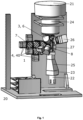
- the aerosol particle measuring device (20) comprises the measuring device (1) with light source (3), detector (4) and measuring chamber (8), as well as an aerosol inlet (21), an aerosol outlet (22), an air flow generation and control device with electronics (23), and is particularly suitable for the qualitative and/or quantitative determination of fluorescent materials (2) in real time by means of fluorescence lifetime measurement in the frequency range, wherein the materials (2) represent aerosol particles of an aerosol, in particular bioaerosol particles dispersed in air such as pollen and/or mold spores.
- the aerosol inlet (21), i.e., the inlet or entrance of the aerosol into the measuring chamber (8), and the aerosol outlet (22), i.e., the outlet or exit of the aerosol from the measuring chamber (8), are known to the person skilled in the art. He or she can also determine the optimal shape for the respective aerosol particle measuring device (20).
- the air flow generation and control device with electronics (23) of the aerosol particle measuring device (20) causes aerosols, typically air containing the materials (2) to be examined, i.e., aerosol particles, to be transported through the aerosol inlet (21) into the measuring chamber (8), along the measuring chamber (8) to the aerosol outlet (22), and thus out of the measuring chamber (8) again.
- the aerosol particle measuring device (20) can have one or more air flow generation and control devices with electronics (23). It is preferably arranged in the region of the aerosol inlet (21) and/or the aerosol outlet (22) of the measuring chamber (8), but can also be arranged in the region of the aerosol inlet (21) and/or the particle concentrator (24). Suitable air flow generation and control devices (23) are known to those skilled in the art.
- the electronics of the air flow generation and control device (23) thus preferably serves to control the sensors and control elements for regulating and controlling the air flow and thus the aerosol particles which are conveyed through the measuring chamber (8) of the aerosol particle measuring device (20).
- the air flow generation and control device (23) comprises, in particular, a pump, nozzle, and control elements, as well as typically at least one sensor, in particular an air velocity sensor, flow sensor, flow rate sensor, air pressure sensor, and/or differential pressure sensor.
- the air flow generation and control device with electronics (23) can be used to control and/or regulate the air flow.
- the aerosol particle measuring device (20) also advantageously comprises a particle concentrator (24), a particle collector (25) and a particle focusing nozzle (28).
- the particle concentrator (24) of the aerosol particle measuring device (20) is optional but often preferred. It allows for the concentration of aerosol particles in the aerosol, enabling faster measurements. A larger number of aerosol particles can be analyzed per measured time unit, thus providing more measured values per unit of time. This allows small particle concentrations to be determined in a shorter time and with greater accuracy.
- Suitable particle concentrators (24) include virtual impactors and cyclones. They are known to those skilled in the art and are commercially available.
- the particle collector (25) of the aerosol particle measuring device (20) is optional and allows the separation, i.e., collection, of the aerosol particles transported through the measuring chamber (8) of the aerosol particle measuring device (20). This can be helpful if the aerosol particles analyzed by fluorescence measurement are to be subsequently analyzed additionally, for example, for duplicate determination and/or microscopy.
- the aerosol particle measuring device (20) has a particle collector (25), no or only a portion of the aerosol particles passed through the measuring chamber (8) exit the aerosol outlet (22).
- Suitable particle collectors (25) are known to the person skilled in the art and are commercially available.
- the at least one particle focusing nozzle (28) of the aerosol particle measuring device (20) is optional, but often preferred. It enables the bundling of the aerosol particles in the aerosol in the trajectory of the measuring chamber (8), so that ideally all, or at least the largest possible proportion, of the aerosol particles in the measuring chamber can be measured.
- the particle focusing nozzle (28) is preferably located between the aerosol inlet (21) or the particle concentrator (24) and the measuring chamber (8). Suitable particle focusing nozzles (28) are known to those skilled in the art.
- the method according to the invention surprisingly allows a qualitative and/or quantitative determination of fluorescent materials (2) in real time by means of fluorescence lifetime measurement with the aerosol particle measuring device (20) according to the invention, comprising the measuring device (1).
- the fluorescence lifetime measurement is carried out in the frequency domain and the light (31) emitted by the light source (3) is intensity modulated.
- At least one diode laser in particular a UV diode laser, a diode-pumped solid-state laser, and/or an LED is used as the light source (3).
- the materials (2), in the form of aerosol particles of an aerosol are measured in the measuring chamber (8) of the measuring device (1) - and thus in the aerosol measuring source (20).
- the aerosol particles in the measuring chamber (8) are exposed to the light (31) of the light source (3), whereby the aerosol particles absorb the light and partially re-emit it.
- the emitted light is detected by the detector (4), which is a semiconductor-based electronic photon detector for light detection, in particular a silicon photomultiplier (SiPM).
- SiPM silicon photomultiplier
- the aerosol particle measuring device (20) according to the invention and the method according to the invention can, surprisingly, be used in a wide variety of ways. They are outstandingly suitable for the qualitative and/or quantitative determination of fluorescent materials (2) in the form of aerosol particles of an aerosol, i.e., aerosol particles dispersed in a gas phase, in particular pollen and/or spores suspended in the air, by means of fluorescence lifetime measurement in the frequency domain, and in particular in real time, as well as in process engineering, for example, for process and/or quality control of materials (2).
Landscapes
- Health & Medical Sciences (AREA)
- Life Sciences & Earth Sciences (AREA)
- Biochemistry (AREA)
- Physics & Mathematics (AREA)
- Chemical & Material Sciences (AREA)
- Analytical Chemistry (AREA)
- Nuclear Medicine, Radiotherapy & Molecular Imaging (AREA)
- General Health & Medical Sciences (AREA)
- General Physics & Mathematics (AREA)
- Immunology (AREA)
- Pathology (AREA)
- Engineering & Computer Science (AREA)
- Biomedical Technology (AREA)
- Molecular Biology (AREA)
- Investigating, Analyzing Materials By Fluorescence Or Luminescence (AREA)
Applications Claiming Priority (2)
| Application Number | Priority Date | Filing Date | Title |
|---|---|---|---|
| EP17189312 | 2017-09-05 | ||
| PCT/EP2018/073306 WO2019048322A2 (de) | 2017-09-05 | 2018-08-30 | Aerosolpartikelmessgerät zur bestimmung von materialien in echtzeit mittels fluoreszenzlebenszeit messung im frequenzbereich |
Publications (3)
| Publication Number | Publication Date |
|---|---|
| EP3679353A2 EP3679353A2 (de) | 2020-07-15 |
| EP3679353B1 true EP3679353B1 (de) | 2025-04-23 |
| EP3679353C0 EP3679353C0 (de) | 2025-04-23 |
Family
ID=59799250
Family Applications (1)
| Application Number | Title | Priority Date | Filing Date |
|---|---|---|---|
| EP18773086.6A Active EP3679353B1 (de) | 2017-09-05 | 2018-08-30 | Aerosolpartikelmessgerät zur bestimmung von materialien in echtzeit mittels fluoreszenzlebenszeit messung im frequenzbereich |
Country Status (5)
| Country | Link |
|---|---|
| EP (1) | EP3679353B1 (pl) |
| ES (1) | ES3032674T3 (pl) |
| HU (1) | HUE072060T2 (pl) |
| PL (1) | PL3679353T3 (pl) |
| WO (2) | WO2019048322A2 (pl) |
Families Citing this family (2)
| Publication number | Priority date | Publication date | Assignee | Title |
|---|---|---|---|---|
| CN111505007A (zh) * | 2020-05-29 | 2020-08-07 | 西北农林科技大学 | 一种空气中真菌孢子无透镜全息图像采集装置 |
| CN112414982A (zh) * | 2020-11-03 | 2021-02-26 | 中国计量大学 | 一种便携式生物气溶胶检测装置及方法 |
Family Cites Families (11)
| Publication number | Priority date | Publication date | Assignee | Title |
|---|---|---|---|---|
| US6594001B1 (en) | 1998-07-27 | 2003-07-15 | Kowa Company, Ltd. | Pollen grain-counting method and pollen grain counter |
| DE10259293A1 (de) * | 2002-12-18 | 2004-07-22 | Giesecke & Devrient Gmbh | Vorrichtung für die Überprüfung der Echtheit von Banknoten |
| IE20030144A1 (en) * | 2003-02-28 | 2004-09-08 | Univ Dublin City | Improved optical sensors |
| EP1699553A2 (en) * | 2003-12-22 | 2006-09-13 | VersaMatrix A/S | Apparatus and methods for analysis and sorting of particles such as polymer beads |
| DE102012102363A1 (de) * | 2011-08-17 | 2013-02-21 | Technische Universität Darmstadt | Verfahren und Vorrichtung zur Bestimmung der Größe eines transparenten Teilchens |
| WO2013066959A1 (en) * | 2011-10-31 | 2013-05-10 | The Trustees Of Columbia University In The City Of New York | Systems and methods for imaging using single photon avalanche diodes |
| UY34599A (es) * | 2012-02-03 | 2013-09-02 | Sicpa Holding Sa | Identificación de relojes y sistema y método de autenticación |
| US8830476B2 (en) * | 2012-03-19 | 2014-09-09 | The United States Of America As Represented By The Secretary Of The Army | Methods and apparatuses for contact-free holographic imaging of aerosol particles |
| US10359414B2 (en) | 2015-03-09 | 2019-07-23 | The Regents Of The University Of Michigan | Frequency domain discrimination of tissue proteins |
| WO2016149701A1 (en) * | 2015-03-19 | 2016-09-22 | The Regents Of The University Of Michigan | System for analyzing tissue |
| EP3408643B1 (en) * | 2016-01-25 | 2021-12-01 | Plair SA | Method and device for detection and/or morphologic analysis of individual fluid-borne particles |
-
2018
- 2018-08-30 WO PCT/EP2018/073306 patent/WO2019048322A2/de not_active Ceased
- 2018-08-30 EP EP18773086.6A patent/EP3679353B1/de active Active
- 2018-08-30 WO PCT/EP2018/073304 patent/WO2019048321A2/de not_active Ceased
- 2018-08-30 PL PL18773086.6T patent/PL3679353T3/pl unknown
- 2018-08-30 ES ES18773086T patent/ES3032674T3/es active Active
- 2018-08-30 HU HUE18773086A patent/HUE072060T2/hu unknown
Also Published As
| Publication number | Publication date |
|---|---|
| EP3679353A2 (de) | 2020-07-15 |
| WO2019048321A3 (de) | 2019-08-08 |
| ES3032674T3 (en) | 2025-07-23 |
| EP3679353C0 (de) | 2025-04-23 |
| WO2019048322A2 (de) | 2019-03-14 |
| PL3679353T3 (pl) | 2025-07-14 |
| HUE072060T2 (hu) | 2025-10-28 |
| WO2019048322A3 (de) | 2019-08-08 |
| WO2019048321A2 (de) | 2019-03-14 |
Similar Documents
| Publication | Publication Date | Title |
|---|---|---|
| US6885440B2 (en) | System and method for detecting and classifying biological particles | |
| CN109196330B (zh) | 用于对生物和非生物粒子进行检测和分类的实时光学方法和系统 | |
| EP3844475B1 (de) | Messsystem zum untersuchen von konzentrierten aerosolpartikeln in der gasphase | |
| DE69738555T2 (de) | Gerät unter Verwendung verschiedener optischer Messverfahren | |
| US6532067B1 (en) | Aerosol fluorescence spectrum analyzer for rapid measurement of single airborne particles | |
| DE102015207289B4 (de) | Partikelsensorvorrichtung | |
| US20170241893A1 (en) | Devices, systems and methods for detecting particles | |
| DE19948587A1 (de) | Spektralphotometrische und nephelometrische Detektionseinheit | |
| DE112011103405T5 (de) | Funkenemissions-Teilchendetektor | |
| EP0257248A2 (de) | Streulichtmessgerät | |
| DE102021105745B4 (de) | Spektrometer-Fluoreszenz-Laserradarsystem mit mehreren Anregungswellenlängen | |
| Robinson et al. | Fluorescence calibration method for single-particle aerosol fluorescence instruments | |
| DE112014000733T5 (de) | Zählsystem für Keimpartikel und Zählmethode für Keimpartikel | |
| US20190113434A1 (en) | Optical Detection Systems and Methods of Using the Same | |
| EP3679353B1 (de) | Aerosolpartikelmessgerät zur bestimmung von materialien in echtzeit mittels fluoreszenzlebenszeit messung im frequenzbereich | |
| EP3704473B1 (de) | Neuartiger sensor für die ramanspektroskopie | |
| EP3884262B1 (de) | Verfahren zum betreiben eines partikelsensors | |
| DE102018203301A1 (de) | Mit Laser induzierter Inkandeszenz arbeitender Partikelsensor mit einer konfokalen Anordnung eines Laserspots und eines Temperaturstrahlungsspots | |
| WO2005017598A1 (de) | Verfahren und vorrichtung zur bestimmung von lumineszierenden molekülen nach der methode der fluoreszenzkorrelationsspektroskopie | |
| DE202006014264U1 (de) | Lidar-System | |
| DE60102797T2 (de) | Fluoreszenzintensitätsanalyse unter verwendung einer vielzahl von verteilungen: konkurrierende bestimmung von diffusionszeiten und molekularer helligkeit | |
| WO2020119990A1 (de) | Verfahren zur detektion von partikeln oder aerosol in einem strömenden fluid, computerprogramm sowie elektrisches speichermedium | |
| DE102010012580A1 (de) | Vorrichtung und Verfahren zur zeitaufgelösten Durchflusszytometrie | |
| DE102014108143A1 (de) | An optical system for detecting fluorescent or luminescent signals of at least two samples | |
| EP4621390A1 (de) | Anordnung und verfahren zur vermessung von partikeln, insbesondere mikroplastikpartikeln, in flüssigkeiten |
Legal Events
| Date | Code | Title | Description |
|---|---|---|---|
| STAA | Information on the status of an ep patent application or granted ep patent |
Free format text: STATUS: UNKNOWN |
|
| STAA | Information on the status of an ep patent application or granted ep patent |
Free format text: STATUS: THE INTERNATIONAL PUBLICATION HAS BEEN MADE |
|
| PUAI | Public reference made under article 153(3) epc to a published international application that has entered the european phase |
Free format text: ORIGINAL CODE: 0009012 |
|
| STAA | Information on the status of an ep patent application or granted ep patent |
Free format text: STATUS: REQUEST FOR EXAMINATION WAS MADE |
|
| 17P | Request for examination filed |
Effective date: 20200401 |
|
| AK | Designated contracting states |
Kind code of ref document: A2 Designated state(s): AL AT BE BG CH CY CZ DE DK EE ES FI FR GB GR HR HU IE IS IT LI LT LU LV MC MK MT NL NO PL PT RO RS SE SI SK SM TR |
|
| AX | Request for extension of the european patent |
Extension state: BA ME |
|
| DAV | Request for validation of the european patent (deleted) | ||
| DAX | Request for extension of the european patent (deleted) | ||
| STAA | Information on the status of an ep patent application or granted ep patent |
Free format text: STATUS: EXAMINATION IS IN PROGRESS |
|
| 17Q | First examination report despatched |
Effective date: 20220524 |
|
| RAP3 | Party data changed (applicant data changed or rights of an application transferred) |
Owner name: SWISENS AG |
|
| GRAP | Despatch of communication of intention to grant a patent |
Free format text: ORIGINAL CODE: EPIDOSNIGR1 |
|
| STAA | Information on the status of an ep patent application or granted ep patent |
Free format text: STATUS: GRANT OF PATENT IS INTENDED |
|
| INTG | Intention to grant announced |
Effective date: 20250114 |
|
| GRAS | Grant fee paid |
Free format text: ORIGINAL CODE: EPIDOSNIGR3 |
|
| GRAA | (expected) grant |
Free format text: ORIGINAL CODE: 0009210 |
|
| STAA | Information on the status of an ep patent application or granted ep patent |
Free format text: STATUS: THE PATENT HAS BEEN GRANTED |
|
| AK | Designated contracting states |
Kind code of ref document: B1 Designated state(s): AL AT BE BG CH CY CZ DE DK EE ES FI FR GB GR HR HU IE IS IT LI LT LU LV MC MK MT NL NO PL PT RO RS SE SI SK SM TR |
|
| REG | Reference to a national code |
Ref country code: GB Ref legal event code: FG4D Free format text: NOT ENGLISH |
|
| REG | Reference to a national code |
Ref country code: CH Ref legal event code: EP |
|
| REG | Reference to a national code |
Ref country code: DE Ref legal event code: R096 Ref document number: 502018015762 Country of ref document: DE |
|
| REG | Reference to a national code |
Ref country code: IE Ref legal event code: FG4D Free format text: LANGUAGE OF EP DOCUMENT: GERMAN |
|
| U01 | Request for unitary effect filed |
Effective date: 20250507 |
|
| U07 | Unitary effect registered |
Designated state(s): AT BE BG DE DK EE FI FR IT LT LU LV MT NL PT RO SE SI Effective date: 20250514 |
|
| REG | Reference to a national code |
Ref country code: ES Ref legal event code: FG2A Ref document number: 3032674 Country of ref document: ES Kind code of ref document: T3 Effective date: 20250723 |
|
| REG | Reference to a national code |
Ref country code: SK Ref legal event code: T3 Ref document number: E 46562 Country of ref document: SK |
|
| REG | Reference to a national code |
Ref country code: GR Ref legal event code: EP Ref document number: 20250401215 Country of ref document: GR Effective date: 20250707 |
|
| U1N | Appointed representative for the unitary patent procedure changed after the registration of the unitary effect |
Representative=s name: STOLMAR & PARTNER INTELLECTUAL PROPERTY GMBH; CH |
|
| PGFP | Annual fee paid to national office [announced via postgrant information from national office to epo] |
Ref country code: HU Payment date: 20250827 Year of fee payment: 8 |
|
| U20 | Renewal fee for the european patent with unitary effect paid |
Year of fee payment: 8 Effective date: 20250821 |
|
| PGFP | Annual fee paid to national office [announced via postgrant information from national office to epo] |
Ref country code: ES Payment date: 20250926 Year of fee payment: 8 |
|
| PGFP | Annual fee paid to national office [announced via postgrant information from national office to epo] |
Ref country code: GR Payment date: 20250822 Year of fee payment: 8 Ref country code: NO Payment date: 20250826 Year of fee payment: 8 |
|
| PGFP | Annual fee paid to national office [announced via postgrant information from national office to epo] |
Ref country code: TR Payment date: 20250825 Year of fee payment: 8 Ref country code: PL Payment date: 20250821 Year of fee payment: 8 |
|
| PGFP | Annual fee paid to national office [announced via postgrant information from national office to epo] |
Ref country code: GB Payment date: 20250820 Year of fee payment: 8 |
|
| PG25 | Lapsed in a contracting state [announced via postgrant information from national office to epo] |
Ref country code: HR Free format text: LAPSE BECAUSE OF FAILURE TO SUBMIT A TRANSLATION OF THE DESCRIPTION OR TO PAY THE FEE WITHIN THE PRESCRIBED TIME-LIMIT Effective date: 20250423 |
|
| PGFP | Annual fee paid to national office [announced via postgrant information from national office to epo] |
Ref country code: CH Payment date: 20250901 Year of fee payment: 8 |
|
| PG25 | Lapsed in a contracting state [announced via postgrant information from national office to epo] |
Ref country code: RS Free format text: LAPSE BECAUSE OF FAILURE TO SUBMIT A TRANSLATION OF THE DESCRIPTION OR TO PAY THE FEE WITHIN THE PRESCRIBED TIME-LIMIT Effective date: 20250723 |
|
| PGFP | Annual fee paid to national office [announced via postgrant information from national office to epo] |
Ref country code: IE Payment date: 20250820 Year of fee payment: 8 Ref country code: CZ Payment date: 20250827 Year of fee payment: 8 |
|
| PGFP | Annual fee paid to national office [announced via postgrant information from national office to epo] |
Ref country code: SK Payment date: 20250828 Year of fee payment: 8 |
|
| PG25 | Lapsed in a contracting state [announced via postgrant information from national office to epo] |
Ref country code: IS Free format text: LAPSE BECAUSE OF FAILURE TO SUBMIT A TRANSLATION OF THE DESCRIPTION OR TO PAY THE FEE WITHIN THE PRESCRIBED TIME-LIMIT Effective date: 20250823 |
|
| REG | Reference to a national code |
Ref country code: HU Ref legal event code: AG4A Ref document number: E072060 Country of ref document: HU |
|
| PG25 | Lapsed in a contracting state [announced via postgrant information from national office to epo] |
Ref country code: SM Free format text: LAPSE BECAUSE OF FAILURE TO SUBMIT A TRANSLATION OF THE DESCRIPTION OR TO PAY THE FEE WITHIN THE PRESCRIBED TIME-LIMIT Effective date: 20250423 |
|
| PGFP | Annual fee paid to national office [announced via postgrant information from national office to epo] |
Ref country code: CY Payment date: 20250812 Year of fee payment: 8 |
|
| PLBE | No opposition filed within time limit |
Free format text: ORIGINAL CODE: 0009261 |
|
| STAA | Information on the status of an ep patent application or granted ep patent |
Free format text: STATUS: NO OPPOSITION FILED WITHIN TIME LIMIT |
|
| REG | Reference to a national code |
Ref country code: CH Ref legal event code: L10 Free format text: ST27 STATUS EVENT CODE: U-0-0-L10-L00 (AS PROVIDED BY THE NATIONAL OFFICE) Effective date: 20260304 |
|
| PG25 | Lapsed in a contracting state [announced via postgrant information from national office to epo] |
Ref country code: MC Free format text: LAPSE BECAUSE OF FAILURE TO SUBMIT A TRANSLATION OF THE DESCRIPTION OR TO PAY THE FEE WITHIN THE PRESCRIBED TIME-LIMIT Effective date: 20250423 |
|
| 26N | No opposition filed |
Effective date: 20260126 |