EP3679201B1 - Baugruppen zum aufhängen von deckenplatten - Google Patents
Baugruppen zum aufhängen von deckenplatten Download PDFInfo
- Publication number
- EP3679201B1 EP3679201B1 EP17847820.2A EP17847820A EP3679201B1 EP 3679201 B1 EP3679201 B1 EP 3679201B1 EP 17847820 A EP17847820 A EP 17847820A EP 3679201 B1 EP3679201 B1 EP 3679201B1
- Authority
- EP
- European Patent Office
- Prior art keywords
- intersection
- members
- support
- assembly
- support members
- Prior art date
- Legal status (The legal status is an assumption and is not a legal conclusion. Google has not performed a legal analysis and makes no representation as to the accuracy of the status listed.)
- Active
Links
Images


Classifications
-
- E—FIXED CONSTRUCTIONS
- E04—BUILDING
- E04B—GENERAL BUILDING CONSTRUCTIONS; WALLS, e.g. PARTITIONS; ROOFS; FLOORS; CEILINGS; INSULATION OR OTHER PROTECTION OF BUILDINGS
- E04B9/00—Ceilings; Construction of ceilings, e.g. false ceilings; Ceiling construction with regard to insulation
- E04B9/06—Ceilings; Construction of ceilings, e.g. false ceilings; Ceiling construction with regard to insulation characterised by constructional features of the supporting construction, e.g. cross section or material of framework members
- E04B9/12—Connections between non-parallel members of the supporting construction
- E04B9/14—Connections between non-parallel members of the supporting construction all the members being discontinuous and laying at least partly in the same plane
-
- E—FIXED CONSTRUCTIONS
- E04—BUILDING
- E04B—GENERAL BUILDING CONSTRUCTIONS; WALLS, e.g. PARTITIONS; ROOFS; FLOORS; CEILINGS; INSULATION OR OTHER PROTECTION OF BUILDINGS
- E04B9/00—Ceilings; Construction of ceilings, e.g. false ceilings; Ceiling construction with regard to insulation
- E04B9/06—Ceilings; Construction of ceilings, e.g. false ceilings; Ceiling construction with regard to insulation characterised by constructional features of the supporting construction, e.g. cross section or material of framework members
- E04B9/10—Connections between parallel members of the supporting construction
-
- E—FIXED CONSTRUCTIONS
- E04—BUILDING
- E04B—GENERAL BUILDING CONSTRUCTIONS; WALLS, e.g. PARTITIONS; ROOFS; FLOORS; CEILINGS; INSULATION OR OTHER PROTECTION OF BUILDINGS
- E04B9/00—Ceilings; Construction of ceilings, e.g. false ceilings; Ceiling construction with regard to insulation
- E04B9/06—Ceilings; Construction of ceilings, e.g. false ceilings; Ceiling construction with regard to insulation characterised by constructional features of the supporting construction, e.g. cross section or material of framework members
- E04B9/12—Connections between non-parallel members of the supporting construction
- E04B9/16—Connections between non-parallel members of the supporting construction the members lying in different planes
-
- E—FIXED CONSTRUCTIONS
- E04—BUILDING
- E04B—GENERAL BUILDING CONSTRUCTIONS; WALLS, e.g. PARTITIONS; ROOFS; FLOORS; CEILINGS; INSULATION OR OTHER PROTECTION OF BUILDINGS
- E04B9/00—Ceilings; Construction of ceilings, e.g. false ceilings; Ceiling construction with regard to insulation
- E04B9/18—Means for suspending the supporting construction
- E04B9/20—Means for suspending the supporting construction adjustable
- E04B9/205—Means for suspending the supporting construction adjustable by means of a resilient clip
-
- E—FIXED CONSTRUCTIONS
- E04—BUILDING
- E04B—GENERAL BUILDING CONSTRUCTIONS; WALLS, e.g. PARTITIONS; ROOFS; FLOORS; CEILINGS; INSULATION OR OTHER PROTECTION OF BUILDINGS
- E04B9/00—Ceilings; Construction of ceilings, e.g. false ceilings; Ceiling construction with regard to insulation
- E04B9/34—Grid-like or open-work ceilings, e.g. lattice type box-like modules, acoustic baffles
Definitions
- the present invention relates to assemblies for suspending ceiling panels, an intersection member for use in those assemblies.
- Suspended ceiling systems provide a grid structure for suspending light-weight panels to form a ceiling in commercial environments such as office or retail spaces.
- the panels can be used to hide the upper space of a room which can contain wiring, conduit, piping or ductwork.
- Designers often desire the installation of visually different suspended ceilings other than those that can suspend standard square or rectangular panels. However this can involve complex and expensive installation.
- US 4,438,613 A discloses a suspended ceiling system having a plurality of removable panels which are supported below a grid network.
- the grid network comprises structural elements interconnected by junction members with the cells of the grid network sized to receive a panel about the periphery thereof.
- the structural members cooperate with framed panel members to accurately align adjacent panels and position them at a certain height below the grid network. Access to the area above the panels is obtained by removal of any of the panel members.
- Each panel is urged into abutting contact with the grid network to provide a seal therewith such that the area above the ceiling may be used as a return air ple
- US 4,398,841 A discloses a coupler portion of a connector assembly for interconnecting vertical columns and horizontal beams, that includes a rectangularly shaped hollow block member having a vertical row of slots formed along the height of each of its sidewalls.
- the block member is connectable to the top or bottom of a vertical column or between two abutting vertical columns by a joiner insert composed of a flat flange section and a transverse stud section extending normally outwardly from one side of the flange to engage within a central hole provided in the end wall of the hollow block member.
- the joiner insert also includes a plug section extending normally outwardly from the flange section in a direction opposite the stud section to engage within a socket formed in the end portion of each column.
- the connector assembly also includes a T-shaped bracket engageable within a vertical slot formed in each end portion of the horizontal beams.
- the bracket includes a plurality of vertically spaced apart downwardly open hooks which slidably engage within, and securely lock with, the block member slots to thereby interconnect the horizontal beams with the end portion of a column or between the ends of two vertically abutting columns.
- Examples of the invention seek to avoid or to at least ameliorate problems of existing suspended ceiling systems.
- intersection member and assemblies including such intersection member for suspending ceiling panels according to the appended claims.
- Figures 1 to 3A are views of assemblies 2, 4 for suspending ceiling panels 6 having respectively a frame 8 or two frames 8, 10, and suspension members 12 according to preferred embodiments of the present invention.
- the suspension members 12 are for suspending the frames 8, 10 from structure, such as an interior surface of a roof or a ceiling of a room.
- the frames 8, 10 have intersection members 14, 16 and support members 18 extending therebetween where each support member 18 supports a side of one of the ceiling panels 6.
- the intersection members 14, 16 have a generally tubular, axially extending, mounting member 19 and a base 15, which base is lowermost in use of the intersection member.
- the base 15 extends outwardly around the periphery of the mounting member 19, as a peripheral flange.
- the ends of the support members 18 are configured to engage with engageable portions 20 provided circumferentially about each of the intersection members 14, 16, the engageable portions 20 defining respective slot-like apertures which extend through the side wall of mounting member 19.
- the support members and intersection members form a support grid having openings principally defined at the peripheries by the support members 18.
- the shape of these openings corresponds to the shape of the ceiling panels 6, each side of the ceiling panel 6 being supportable by a respective support member 18. That is, the support members 18 have flanges 13 on lower opposite longitudinal edges which receive thereon underside marginal portions of the ceiling panels 6, thereby supporting the ceiling panels 6 to form a suspended ceiling as shown in Figure 3A .
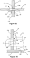
- Figures 3B to 3K show more detailed examples of the engagement of the support members 18 with the intersection member 14 or 16, where the engageable portions 20 are provided as apertures 11 which are adapted to receive protrusions 17 provided at the opposite ends of the support members 18.
- the engageable portions may be in the form of protrusions which are receivable in apertured portions provided at the opposed ends of the support members 18.
- the illustrated protrusion 17 is latchingly engaged in an aperture 11.
- the protrusion 17 is latchingly engaged laterally in the aperture 11. Both embodiments will be described further below.
- the intersection members 14, 16 are shown with the engageable portions 20 in the form of the described apertures 11 formed through the side wall 19a of the mounting member 19 and being arranged towards an end of the mounting member adjacent to the base 15 of the intersection member 14, 16.
- the locating member 23 is in the form of a punched-out resilient tongue extending sidewardly, and outwardly at an acute angle, from the remainder of the protrusion 17.
- the width S of the aperture 11 is only slightly greater than the width W1 of the main body of the protrusion 17.
- the width W2 is greater than the width S.
- the protrusion 17 can pass through the aperture 11 until the locating member 23 has passed through it. Once the locating member 23 is clear of the aperture 11, the free end 23a of the locating member 23 moves outwardly under resilient bias (in the direction indicated by arrow C in Figure 3J ) from the protrusion 17 so that withdrawal of the support member 18 is inhibited by engagement of the free end 23a of the locating member 23 with the inner surface 19b of the side wall 19a of the mounting member 19 forming part of the intersection member 14 or 16.
- protrusion 17 may have locating members 25 and/or 27 to provide an alternative engagement to inhibit further movement of the protrusion 17 into intersection member 14 or 16.
- inwards movement of the protrusion 17 into the aperture 11, as mentioned, may be limited by engagement between a side edge 15a of the base 15 of the intersection member 14, 16 and a lower transverse 13a surface of the flanges 13 of the support member 18.
- a transverse locating member 29, forming parts of flange 13, extends side to side of the support member 18, slightly above the main lengthwise extending parts 13b ( Figure 3K ) of the flanges 13, so as to define a step between the flanges and the transverse locating member 29. It is at this step that the surface 13a is defined; that is, as an end surface of flange parts 13b.
- the transverse locating member 29 rests on the base 15 so as to additionally or alternatively support the support member.
- inwards insertion of the protrusion may be limited by providing on the protrusion 17 a further locating member 28, shown in phantom lines in Figures 3J and 3K and in the form of a punched out tongue, like locating member 23, but oppositely directed, and with its free end 28a spaced from the free end of locating member by a distance substantially the same as the thickness of the wall 19a.
- the free end 18a is as shown brought into engagement with the outer surface of the wall 19a, to prevent further inwards movement.
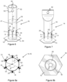
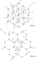
- intersection members 14, 16, shown in Figures 6 to 8b have engageable portions 20 arranged equiangularly about the circumference of the intersection members 14, 16 wherein the angles formed between the engageable portions 20 and an axis 21 of the intersection members 14, 16 are represented as angle A, which corresponds to 60° (see Figure 8a ).
- This angle A corresponds to the angle of a corner of an equilateral triangle, known as an interior angle. Therefore the assemblies 2, 4 having intersection members 14, 16 and support members 18 form a grid 22 in which there are openings which can suspend ceiling panels 6 in the shape of equilateral triangles to form a suspended ceiling 24.
- intersection members 14, 16 and support members 18 can be used to form a grid 26 whereby the ends of adjacent support members 18 engaged in intersection members 14, 16 form an angle of 120° represented as B in Figures 5 , 8a and 10 .
- Angle B is the interior angle of a hexagon.
- the openings of the grid 26 therefore can receive and suspend hexagonal shaped ceiling panels 25, see Figures 5 , 8a and 10 .
- the same intersection members 14, 16 can be used to form an assembly for suspending panels of equilateral triangle shape or hexagonal shape or a combination therefore, depending on the configuration of members 14, 16, 18.
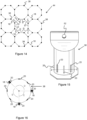
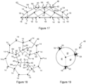
- FIG. 11 to 19 Further embodiments of the present invention are directed to similar assemblies as described above but for suspending ceiling panels having square, octagonal or pentagonal shaped ceiling panels, see Figures 11 to 19 .
- the angle between ends of adjacent support members engaged in the intersection members 36, 38, 40 can form angles C, D and E being respectively angles of 90°, 135° and 108° (corresponding to the interior angles of quadrilaterals, octagons and pentagons) to form the exemplary grids 42, 44, 46.
- the openings of grids 42, 44, 46 can receive ceiling panels having the shapes of squares, octagons and pentagons. While the grid 42 is for suspending square ceiling panels, it can be understood that any quadrilateral ceiling panels, such as rectangular panels could be utilized by varying the length of the support members 18 as appropriate.
- Figure 3A is a view of an assembly having two frames 8, 10 in a spaced apart vertical configuration.
- the intersection member 14, 16 of each frame 8, 10 is engageable with the suspension members 12 such that one intersection member 16 of the two frames 8, 10 is supported above the other intersection member 14, each frame being able to receive at least one ceiling panel 6.
- the intersection members 14, 16 attach to the suspension members 12 by a fastener 50 such as a suspension clip.
- the fastener 50 is releasably attachable to the suspension member 12 such that the intersection member 14, 16 can be movably adjustable along the length of the suspension member 12, which can be in the form of a rod, to allow adjustment of the vertical distance between the frames 8, 10 or the adjustment of the height of the suspended ceiling.
- the intersection members 14, 16 can be attached to the fasteners 50, in particular the lower end portion of the fastener 50 is configured as a hook 58 which can be received in an apertured portion 52 of the intersection members 14, 16.
- Each intersection member 16 on an upper portion of the suspension member 12 has an opening 54 configured to allow the suspension member 12 to be received therethrough such that an axis of the suspension member 12 is substantially parallel to an axis of the intersection member 16 so that the intersection members 14, 16 are spaced-apart substantially vertically one above the other.
- the aperture 54 is substantially the size of the diameter of the suspension member 12 and is preferably centrally located within a base 15 of the intersection member 16.
- transverse element 55 there is a transverse element internal to the intersection member 16, the transverse element 55 having a second aperture 57 and where the transverse element 55 is spaced apart from the base 15 along the longitudinal axis within the body of the intersection member 16 to ensure that the intersection members 14, 16 are accurately positioned vertically, one above the other.
- FIG. 4 An example suspended ceiling 24 having three levels is shown in Figure 4 . Further frames could be engaged with the suspension members 12 so as to provide a suspended ceiling with four or more levels. Alternatively the assemblies can be arranged with the intersection members 36, 38, 40 as shown in Figures 12, 13 , 15, 16 and 19 so as to form a suspended ceiling with one or more levels having quadrilateral, pentagonal or octagonal shaped ceiling panels or combinations thereof.
- each level does not need to be occupied by ceiling panels so they are viewed from below of complete coverage.
- ceiling panels 60 can be received between adjacent intersection members 14, 16 on the same suspension member 12 such that the ceiling panels 60 lie perpendicular to the plane of the frames 8, 10.
- a user can assemble a suspended ceiling with ceiling panels having an equilateral triangle shape 6.
- the user can first assemble a frame 8 with intersection members 14 where the ends of six support members 18 are engaged with each of the six engageable portions 20 provided equiangularly about each of the intersection members 14 so as to form a grid 22, see Figure 9 .
- the ends of adjacent support members 18 form an angle A of 60° (the interior angle of an equilateral triangle).
- the user can then attach each intersection member 14 to a fastener 50 on a rod-shaped suspension member 12, the top portion of which is fixed to structure such as a ceiling of a room or an interior surface of a roof.
- the suspended ceiling 24 is thereby formed when the user provides equilateral triangle shaped ceiling panels 6 in the correspondingly shaped recesses formed by the grid 22, the panels being held in the respective recesses by flanges provided on the support members 18.
- the user can assemble a second frame 10 which is spaced apart vertically above the first frame 8, in the same way as described for the first frame 8 above.
- the user can then attach the second frame 10 to an upper portion of the suspension member 12 by a second fastener 50.
- the resultant assembly has first and second frames 8, 10 which are substantially parallel but spaced apart as shown in Figure 3A .
- each intersection member 38 receives ends of three support members 18 to form two angles D of 135° and one angle C of 90° thereby forming the grid 32 having both octagonal and square shaped recesses to configured to receive correspondingly shaped octagonal and square ceiling panels, see Figure 16 .
- intersection member 38 Although eight engageable portions 20 are shown on the intersection member 38, clearly at a minimum only three engageable portions which form the two angles D of 135° and one angle C of 90° as described above would be necessary to form the required assembly. It can be understood that the intersection members 38 may also be used to form a grid 30 for suspending ceiling panels having only quadrilateral shaped recesses.
- Figures 9 to 11 , 14 show exemplary grids which are substantially planar, however Figures 18 and 19 are schematic diagrams showing an opening 46 for suspension of a pentagonal shaped ceiling panel which is the apex of a dome-like grid 62.
- the dome-like grid 62 is formed by intersection members 40 that can have two adjacent support members 18 engaged therein to form an angle which corresponds to the interior angle of a pentagon, represented as angle E of 108°.
- the other support member 64 forms angles, B' of 126° each, with the first two adjacent support members 18.
- the angle formed by the support members 18, 64 decreases to 120°, represented as angle B, to accommodate the interior angle of a hexagon shaped ceiling panel, thereby forming the dome-like grid 62.
- intersection members 14, 16, 36, 38, 40 as having engageable portions in the form of slot like apertures enables these to be used to interconnect with support members 18 of a variety of commercially available ceiling support systems.
- the support members of these systems generally have inverted T-shaped cross sectional form with a central web, upright in use, and sidewardly extended flanges, one to either side of the central web and at a lower edge of the central web in use of the support members.
- support members from different systems are generally incompatible with each other in the sense that the end protrusions of the support members and the configuration of slots, formed in the central webs, and, which accept the end protrusions are differently configured, such that interchangeability is precluded.
- This incompatibility may for example particularly arise because intersections between support members are formed by passing end protrusions of two support members oppositely into a single slot in another support member, such that the protrusions cooperate with each other and with the slot to effect latching.
- this incompatibility problem is lessened because the engageable portions 20 only need to accommodate one protrusion. It has been found that forming the engageable portions 20 as elongate rectangular apertures of about 3mm width by 12mm length, in the axial direction of the intersection member, enables protrusions of various commercially available support members to be used in practicing the invention.
- the dimensions of the rectangular apertures can vary in length by one or two mm so as to accommodate the variable dimensions of the commercially available support members, so that the apertures can be between 11 to 13 mm in length and 1 to 3 mm wide.
- these apertures may terminate close to the base 15 and with the longer dimensions of the slots aligned in the axial direction of the intersection members.
- the length of the apertures 11 in the axial direction of the intersection members may be chosen to suit a particular form of protrusions 17 of the support members 18 being used. As shown the length may be somewhat greater than the upper to lower edge dimension of the protrusions. This may enable use of the intersection members of various different forms of support members, although it may be preferable, mechanically, to make the length only a clearance fit with the upper to lower edge dimension.
- intersection members as having a generally tubular mounting member 19 and a base 15, of polyhedral form with the number of edge surfaces 15a corresponding to the number of engageable portions 20, enables a neat appearance of the completed ceiling to be achieved, as for example, shown in Figure 5 . That is, the base 15 effectively covers the region where the protrusion 17 engaged with the engageable portions 20. Also, as described with reference to Figure 3K , the edge surface 13a of each support member 18 neatly engages an adjacent edge surface 15a, likewise presenting a neat finish.
- the edge surfaces 15a of the base 15 are, when the depicted intersection member is viewed in plan, disposed at 90 degrees to an imaginary line from the axis of the intersection member through the engageable portion 20 and, when viewed from the side, each engageable portion is disposed centrally with respect to the adjacent surface 15a.
- the form of the base may be polyhedral, with the number of sides corresponding to the number of engageable portions 20, as mentioned.
- the base may be regular polygonal although, for example, corners of the polygonal form may be cut off as illustrated in Figure 12 .
- the base 15 provides support portions 15b shown for example in Figure 3E , one supporting each support member fitted to the intersection member, and thus arrayed in an array about the axis of the intersection member, preferably equiangularly arrayed as shown for example in Figure 8A .
- the latching between the engageable portions 20 and the support members 18 is effective to prevent inwards and outwards movement of the support members relative to the intersection members. This may effectively lock support members to the intersection members in the sense that they cannot be separated without defamation of one or more components, permanent or otherwise.
Landscapes
- Engineering & Computer Science (AREA)
- Architecture (AREA)
- Physics & Mathematics (AREA)
- Electromagnetism (AREA)
- Civil Engineering (AREA)
- Structural Engineering (AREA)
- Joining Of Building Structures In Genera (AREA)
- Supports Or Holders For Household Use (AREA)
Claims (15)
- Kreuzungselement (14, 16) mit in Eingriff bringbaren Abschnitten (20), die um den Umfang eines Befestigungselements (19) davon angeordnet sind, wobei das Befestigungselement (19) eine rohrförmige Konfiguration aufweist und die in Eingriff bringbaren Abschnitte (20) schlitzartige Öffnungen (11) sind, die sich in einer axialen Richtung des Befestigungselements (19) erstrecken und durch die Wand des Befestigungselements (19) verlaufen und so beschaffen sind, dass sie Endvorsprünge von Stützelementen (18) einer abgehängten Decke aufnehmen und mit diesen in Eingriff kommen, sodass sich die Endvorsprünge, wenn sie auf diese Weise aufgenommen werden, von dem Kreuzungselement (14, 16) nach außen erstrecken, um eine Abstützung für Deckenplatten (6) bereitzustellen, wobei die in Eingriff bringbaren Abschnitte (20) neben einem Ende des Befestigungselements (19) angeordnet sind, an dem ein Sockel (15) vorgesehen ist, dadurch gekennzeichnet, dass sich der Sockel (15) als Umlaufflansch nach außen um den Umfang des als Befestigungselements (19) erstreckt, um Stützabschnitte (15b) für jedes der Stützelemente (18) bereitzustellen, wenn sie an dem verwendeten Kreuzungselement (14, 16) angebracht sind.
- Baugruppe (2, 4) zum Aufhängen von Deckenplatten (6) mit einem Rahmen (8, 10) und Aufhängungselementen (12) zum Aufhängen des Rahmens (8, 10) an einer Struktur, wobei der Rahmen (8, 10) Kreuzungselemente (14, 16) nach Anspruch 1 und sich dazwischen erstreckende Stützelemente (18) aufweist, wobei jedes Stützelement (18) zum Abstützen einer jeweiligen Seite der Deckenplatte (6) dient, wobei jeder der in Eingriff bringbaren Abschnitte (20) in Umfangsrichtung um jedes der Schnittelemente (14, 16) herum vorgesehen ist und so beschaffen ist, dass er ein Ende eines der Stützelemente (18) aufnehmen kann, wobei die Enden der Stützelemente (18) so konfiguriert sind, dass sie durch die in Eingriff bringbaren Abschnitte (20) hindurchragen, um mit diesen in Eingriff zu kommen.
- Baugruppe (2, 4) nach Anspruch 2 mit mindestens zwei der Rahmen (8, 10), wobei die Aufhängungselemente (12) so beschaffen sind, dass sie mit dem Rahmen (8, 10) in Eingriff kommen, um die Rahmen (8, 10) in einer voneinander beabstandeten vertikalen Anordnung übereinander zu halten, wodurch eine abgehängte Decke mit mindestens zwei Ebenen entsteht.
- Baugruppe (2, 4) zum Aufhängen von Deckenplatten (6) mit mindestens zwei Rahmen (8, 10) und Aufhängungselementen (12) zum Aufhängen der Rahmen (8, 10) an einer Struktur, wobei jeder Rahmen (8, 10) Kreuzungselemente (14, 16) nach Anspruch 1 und Stützelemente (18) aufweist, die sich dazwischen erstrecken, um eine jeweilige Seite der Deckenplatten (6) abzustützen,wobei mindestens einige der Aufhängungselemente (12) so beschaffen sind, dass sie die mindestens zwei Rahmen (8, 10) in einer beabstandeten vertikalen Anordnung abstützen, wobei ein entsprechendes Paar der Kreuzungselemente (14, 16) von jedem der mindestens zwei Rahmen (8, 10) mit einem der Aufhängungselemente (12) in Eingriff gebracht werden kann, sodass eines der beiden Kreuzungselemente (14, 16) in weitgehend vertikaler Ausrichtung über dem anderen Kreuzungselement (14, 16) des Paars gehalten wird; undwobei entgegengesetzte Enden der Stützelemente (18) so konfiguriert sind, dass sie durch einen einer Vielzahl von in Eingriff bringbaren Abschnitten (20) hindurchragen, die in Umfangsrichtung um jedes der Kreuzungselemente (14, 16) herum vorgesehen sind und die so beschaffen sind, eines der entgegengesetzten Enden der Stützelemente (18) aufzunehmen.
- Baugruppe (2, 4) nach Anspruch 4, wobei das Kreuzungselement (14, 16) des Paars der Kreuzungselemente (14, 16), das mit einem oberen Abschnitt des einen der Aufhängungselemente (12) in Eingriff steht, eine Öffnung (54) in einem Sockel (15) davon aufweist, wobei die Öffnung (54) so konfiguriert ist, dass das Aufhängungselement (12) durch sie hindurch aufgenommen werden kann.
- Baugruppe (2, 4) nach einem der Ansprüche 2 bis 5, wobei die in Eingriff bringbaren Abschnitte (20) so angeordnet sind, dass die Winkel zwischen benachbarten Enden der Kreuzungselemente (14, 16), die so in Eingriff mit den Stützelementen (18) stehen, den jeweiligen Innenwinkeln der Deckenplatte (6) entsprechen, wodurch ein Gitter zum Aufhängen der Deckenplatten (6) gebildet wird.
- Baugruppe (2, 4) nach Anspruch 6, wobei die in Eingriff bringbaren Abschnitte (20) gleichwinklig um das (die) Kreuzungselement(e) (14, 16) angeordnet sind.
- Baugruppe (2, 4) nach einem der Ansprüche 2 bis 7, wobei der Rahmen (8, 10) Stützelemente (18) aufweist, die so in die Kreuzungselemente (14, 16) in Eingriff stehen, dass sie eine Öffnung definieren, wobei die Form der Öffnung der Form einer der Deckenplatten (6) entspricht, wobei jede Seite der einen der Deckenplatten (6) durch ein jeweiliges Stützelement (18) abgestützt werden kann.
- Baugruppe (2, 4) nach einem der Ansprüche 2 bis 8, wobei die Enden von jedem der Stützelemente (18) einen Vorsprung (17) definieren, der so angeordnet ist, dass er mit einem der entsprechenden in Eingriff bringbaren Abschnitte (20) rastend in Eingriff kommt, sobald er bei der Verwendung dort hindurchgeführt wurde.
- Baugruppe (2, 4) nach Anspruch 9, wobei der Vorsprung mindestens ein Positionierungselement (23) aufweist, um ein Herausziehen des Vorsprungs (17) aus dem jeweiligen der in Eingriff bringbaren Abschnitte (20) zu verhindern, sobald er bei der Verwendung durch diesen hindurchgeführt wurde.
- Baugruppe (2, 4) nach einem der Ansprüche 2 bis 10, wobei das Aufhängungselement (12) die Form einer Stange hat.
- Baugruppe (2, 4) nach einem der Ansprüche 2 bis 11, wobei jedes Kreuzungselement (14, 16) mit dem Aufhängungselement (12) durch ein Befestigungselement (50) in Eingriff gebracht werden kann und ein unterer Endabschnitt des Befestigungselements (50) als ein Haken konfiguriert ist, der in einem weiteren mit Öffnungen versehenen Abschnitt (52) des Kreuzungselements (14, 16) aufgenommen werden kann.
- Kreuzungselement (14, 16) nach Anspruch 1, wobei der Sockel (15) eine Anordnung von sich nach außen erstreckenden Stützabschnitten (15b) zur Abstützung von Stützelementen (18) definiert, deren Vorsprünge (17) in den in Eingriff bringbaren Abschnitten (20) aufgenommen werden.
- Kreuzungselement (14, 16) nach Anspruch 13, wobei die in Eingriff bringbaren Abschnitte (20) gleichwinklig um das Kreuzungselement (14, 16) angeordnet sind.
- Baugruppe (2, 4) nach Anspruch 2 oder 3, wobei die in Eingriff bringbaren Abschnitte (20) gleichwinklig um das Kreuzungselement (14, 16) angeordnet sind.
Applications Claiming Priority (3)
| Application Number | Priority Date | Filing Date | Title |
|---|---|---|---|
| AU2016903619A AU2016903619A0 (en) | 2016-09-08 | Assemblies for suspending ceiling panels | |
| AU2017900468A AU2017900468A0 (en) | 2017-02-14 | Assemblies for suspending ceiling panels | |
| PCT/AU2017/050977 WO2018045427A1 (en) | 2016-09-08 | 2017-09-08 | Assemblies for suspending ceiling panels |
Publications (4)
| Publication Number | Publication Date |
|---|---|
| EP3679201A1 EP3679201A1 (de) | 2020-07-15 |
| EP3679201A4 EP3679201A4 (de) | 2021-04-28 |
| EP3679201C0 EP3679201C0 (de) | 2025-04-30 |
| EP3679201B1 true EP3679201B1 (de) | 2025-04-30 |
Family
ID=61561259
Family Applications (1)
| Application Number | Title | Priority Date | Filing Date |
|---|---|---|---|
| EP17847820.2A Active EP3679201B1 (de) | 2016-09-08 | 2017-09-08 | Baugruppen zum aufhängen von deckenplatten |
Country Status (5)
| Country | Link |
|---|---|
| US (2) | US11286666B2 (de) |
| EP (1) | EP3679201B1 (de) |
| CN (1) | CN111819335A (de) |
| AU (1) | AU2017325112B2 (de) |
| WO (1) | WO2018045427A1 (de) |
Families Citing this family (3)
| Publication number | Priority date | Publication date | Assignee | Title |
|---|---|---|---|---|
| US11525261B2 (en) * | 2018-03-21 | 2022-12-13 | Worthington Armstrong Venture | Suspended ceiling connectors for unique grid designs |
| US11692345B2 (en) * | 2020-06-30 | 2023-07-04 | Usg Interiors, Llc | Modular dynamic acoustic ceiling panel |
| CN116241053A (zh) * | 2023-02-10 | 2023-06-09 | 上海市建筑装饰工程集团有限公司 | 一种三角形板块吊顶金属板与设备带组合体系的安装方法 |
Citations (1)
| Publication number | Priority date | Publication date | Assignee | Title |
|---|---|---|---|---|
| US4398841A (en) * | 1979-11-30 | 1983-08-16 | Matsushita Electric Works, Ltd. | Column-to-beam connector |
Family Cites Families (48)
| Publication number | Priority date | Publication date | Assignee | Title |
|---|---|---|---|---|
| US2240592A (en) * | 1938-10-29 | 1941-05-06 | Wilson Edwin Bird | Prefabricated housing |
| US3089570A (en) * | 1959-07-21 | 1963-05-14 | Jr Timothy H O'neil | Beam and tie support |
| US3096862A (en) * | 1960-09-07 | 1963-07-09 | W J Haertel & Co | Ceiling suspension system with double locking clip |
| US3097730A (en) * | 1960-11-14 | 1963-07-16 | Roger J Halle | Connection of structural elements in the art of building |
| US3466830A (en) * | 1968-03-28 | 1969-09-16 | Ving Smith | Ceiling installation |
| US3696571A (en) * | 1969-12-29 | 1972-10-10 | Armstrong Cork Co | Sub-ceiling for buildings |
| US3785110A (en) * | 1971-01-14 | 1974-01-15 | Illinois Tool Works | Modular ceiling connector |
| AT326877B (de) * | 1971-09-22 | 1976-01-12 | Doubrava Kg | Gebaude |
| DE2435978A1 (de) * | 1974-07-26 | 1976-02-12 | Odenwald Faserplatten | Stuetzkonstruktion fuer wand- oder deckenverkleidungen |
| DE2728912A1 (de) * | 1977-06-27 | 1979-01-18 | Koenig Ursula | Aufhaengevorrichtung fuer decken, insbesondere zwischendecken |
| US4235559A (en) * | 1979-06-14 | 1980-11-25 | Industrial Management Company | Construction of metal articles |
| US4294054A (en) * | 1979-08-09 | 1981-10-13 | United States Gypsum Company | Soffit system for suspended ceiling |
| US4438613A (en) | 1981-06-25 | 1984-03-27 | Decoustics Limited | Suspended ceiling panel system |
| US4548010A (en) * | 1981-06-25 | 1985-10-22 | Decoustics Limited | Concealed suspended ceiling system |
| US4494350A (en) * | 1982-09-20 | 1985-01-22 | Ceiling Dynamics, Inc. | Aluminum suspension system |
| US4549375A (en) * | 1983-06-07 | 1985-10-29 | Simplex Ceiling Corporation | Ceiling construction |
| US4724650A (en) * | 1986-09-30 | 1988-02-16 | Usg Corporation | Subceiling beam intersection |
| DE3734743A1 (de) * | 1987-10-09 | 1989-04-27 | Semperlux Gmbh | Deckensystem |
| US5289665A (en) * | 1991-09-26 | 1994-03-01 | Higgins Gregory J | Orthogonal framework for modular building systems |
| US5469681A (en) * | 1994-03-09 | 1995-11-28 | Wu; Ming-Hsin | Vinyl ceiling grid structure |
| USD373831S (en) * | 1995-03-16 | 1996-09-17 | Blockbuster Entertainment Inc. | Ceiling |
| US5803782A (en) * | 1996-08-28 | 1998-09-08 | Selton; Daniel E. | Universal connector |
| US5839246A (en) * | 1996-09-12 | 1998-11-24 | Worthington Armstrong Venture | Grid framework for suspended ceiling |
| US6192634B1 (en) * | 1996-09-20 | 2001-02-27 | Temcor | Dual network dome structure |
| US5996288A (en) * | 1997-10-20 | 1999-12-07 | Aiken; Ernest G | Geodesic domes and improved joints therefor |
| DE19803080A1 (de) * | 1998-01-28 | 1999-07-29 | Meissner & Wurst | Deckenraster für Reinräume |
| US6735917B1 (en) * | 2000-12-29 | 2004-05-18 | Dalles C. Notermann | Connected frame structure and method of connecting frame members |
| US20050072090A1 (en) * | 2001-04-20 | 2005-04-07 | Mclaughlin Thomas | Ceiling suspension with cable pathway |
| US6782670B2 (en) * | 2001-12-28 | 2004-08-31 | Usg Interiors, Inc. | Multi-planar ceiling system |
| USD517900S1 (en) * | 2002-04-04 | 2006-03-28 | 420820 Ontario Limited | Bushing |
| US6766623B1 (en) * | 2003-03-18 | 2004-07-27 | Peter A. Kalnay | Foldable, expandable framework for a variety of structural purposes |
| US7926238B2 (en) * | 2004-01-09 | 2011-04-19 | Worthington Armstrong Venture | Stab-in connector |
| CN100572709C (zh) | 2004-03-31 | 2009-12-23 | 海沃氏家具(上海)有限公司 | 薄墙板系统 |
| CN201003223Y (zh) * | 2007-01-10 | 2008-01-09 | 陈华良 | 适用于大空间双曲面天花吊顶的三角形骨架单元 |
| US7770349B2 (en) * | 2008-07-14 | 2010-08-10 | Usg Interiors, Inc. | Seismic clip for grid tee control joint |
| WO2010102388A1 (en) * | 2009-03-10 | 2010-09-16 | Les Plafonds Embassy Inc./Embassy Ceiling Inc. | Clip assembly for use with a suspended ceiling |
| US8079192B2 (en) * | 2010-03-11 | 2011-12-20 | Decoustics Limited | Suspended ceiling grid system |
| US8469438B2 (en) * | 2011-04-28 | 2013-06-25 | GM Global Technology Operations LLC | Door trim fastener |
| DK2546430T4 (en) | 2011-07-12 | 2017-03-13 | Saint-Gobain Ecophon Ab | Suspended ceiling system and method for hanging such a ceiling system |
| CA2866575C (en) * | 2012-03-09 | 2020-04-14 | The Regents Of The University Of Michigan | Dynamically responsive acoustic tuning envelope system and method |
| US8590216B1 (en) * | 2012-06-22 | 2013-11-26 | John Morgan Hurt, III | Locking collar for space frame construction |
| US20140037366A1 (en) | 2012-07-31 | 2014-02-06 | Usg Interiors, Llc | Grid runner intersection clip |
| CN202866098U (zh) * | 2012-10-24 | 2013-04-10 | 浙江德莱宝卫厨科技有限公司 | 一种双层铝型材错层式吊顶结构 |
| CN204311636U (zh) * | 2014-10-28 | 2015-05-06 | 杨炳 | 一种新型网格式吊顶系统 |
| US10094104B2 (en) * | 2015-05-12 | 2018-10-09 | Gregory Higgins | Orthogonal framework for modular resilient houses |
| US10962207B2 (en) * | 2016-04-25 | 2021-03-30 | Worthington Armstrong Venture | Hub for lighting at grid intersection |
| US10610716B2 (en) * | 2017-06-08 | 2020-04-07 | Anvil International, Llc | Sprinkler drop bracket for intersecting downlight |
| CA3113786C (en) * | 2018-10-24 | 2023-06-27 | Price Industries Limited | Ceiling beam grid |
-
2017
- 2017-09-08 EP EP17847820.2A patent/EP3679201B1/de active Active
- 2017-09-08 US US16/645,681 patent/US11286666B2/en active Active
- 2017-09-08 CN CN201780096322.2A patent/CN111819335A/zh active Pending
- 2017-09-08 WO PCT/AU2017/050977 patent/WO2018045427A1/en not_active Ceased
- 2017-09-08 AU AU2017325112A patent/AU2017325112B2/en active Active
-
2022
- 2022-02-16 US US17/673,330 patent/US12227943B2/en active Active
Patent Citations (1)
| Publication number | Priority date | Publication date | Assignee | Title |
|---|---|---|---|---|
| US4398841A (en) * | 1979-11-30 | 1983-08-16 | Matsushita Electric Works, Ltd. | Column-to-beam connector |
Also Published As
| Publication number | Publication date |
|---|---|
| AU2017325112B2 (en) | 2025-02-13 |
| EP3679201A1 (de) | 2020-07-15 |
| US20200263424A1 (en) | 2020-08-20 |
| CN111819335A (zh) | 2020-10-23 |
| US20220170266A1 (en) | 2022-06-02 |
| EP3679201A4 (de) | 2021-04-28 |
| NZ763249A (en) | 2025-05-02 |
| AU2017325112A1 (en) | 2020-06-18 |
| US11286666B2 (en) | 2022-03-29 |
| EP3679201C0 (de) | 2025-04-30 |
| US12227943B2 (en) | 2025-02-18 |
| WO2018045427A1 (en) | 2018-03-15 |
Similar Documents
| Publication | Publication Date | Title |
|---|---|---|
| US11773591B2 (en) | Apparatus and system for dynamic acoustic ceiling system and methods thereof | |
| US12442186B2 (en) | Ceiling system and ceiling baffle thereof | |
| US12227943B2 (en) | Assemblies for suspending ceiling panels | |
| US11933045B2 (en) | Ceiling system | |
| RU2116412C1 (ru) | Приподнятый панельный пол низкого профиля с металлической опорной конструкцией | |
| US4426822A (en) | Vertical ceiling assembly and stringer therefor | |
| US4019300A (en) | Suspended ceiling structure | |
| CA3037547C (en) | Self-centering ceiling panel | |
| US3677589A (en) | Field installation clip for exposed grid systems | |
| US12456446B2 (en) | Apparatus and system for dynamic high NRC acoustic locking wall tile and methods thereof | |
| KR101305094B1 (ko) | 그리드 티이를 매달기 위한 시트 금속 스프레더 클립, 방법, 장치 및 구조체 | |
| US7143562B2 (en) | Suspension system and structure for securing border ceiling panels | |
| US4089146A (en) | Suspended ceiling | |
| US5050360A (en) | Suspended ceiling panel | |
| EP2951366B1 (de) | Klammer für umfangsverkleidung | |
| US7634881B2 (en) | Cross panel | |
| JPH057369Y2 (de) | ||
| JP3213598B2 (ja) | 天井パネルの目地スペーサー | |
| WO2021059251A1 (en) | Clips, a clip system for panels, a trellis assembly and a trellis system | |
| CA1311597C (en) | Partition clip | |
| US20240368883A1 (en) | Ceiling system | |
| JPS6231133B2 (de) |
Legal Events
| Date | Code | Title | Description |
|---|---|---|---|
| STAA | Information on the status of an ep patent application or granted ep patent |
Free format text: STATUS: THE INTERNATIONAL PUBLICATION HAS BEEN MADE |
|
| PUAI | Public reference made under article 153(3) epc to a published international application that has entered the european phase |
Free format text: ORIGINAL CODE: 0009012 |
|
| STAA | Information on the status of an ep patent application or granted ep patent |
Free format text: STATUS: REQUEST FOR EXAMINATION WAS MADE |
|
| 17P | Request for examination filed |
Effective date: 20200403 |
|
| AK | Designated contracting states |
Kind code of ref document: A1 Designated state(s): AL AT BE BG CH CY CZ DE DK EE ES FI FR GB GR HR HU IE IS IT LI LT LU LV MC MK MT NL NO PL PT RO RS SE SI SK SM TR |
|
| AX | Request for extension of the european patent |
Extension state: BA ME |
|
| DAV | Request for validation of the european patent (deleted) | ||
| DAX | Request for extension of the european patent (deleted) | ||
| A4 | Supplementary search report drawn up and despatched |
Effective date: 20210330 |
|
| RIC1 | Information provided on ipc code assigned before grant |
Ipc: E04B 9/14 20060101AFI20210324BHEP Ipc: E04B 9/16 20060101ALI20210324BHEP Ipc: E04B 9/34 20060101ALN20210324BHEP Ipc: E04B 9/20 20060101ALN20210324BHEP |
|
| STAA | Information on the status of an ep patent application or granted ep patent |
Free format text: STATUS: EXAMINATION IS IN PROGRESS |
|
| 17Q | First examination report despatched |
Effective date: 20230406 |
|
| GRAP | Despatch of communication of intention to grant a patent |
Free format text: ORIGINAL CODE: EPIDOSNIGR1 |
|
| STAA | Information on the status of an ep patent application or granted ep patent |
Free format text: STATUS: GRANT OF PATENT IS INTENDED |
|
| INTG | Intention to grant announced |
Effective date: 20240523 |
|
| GRAS | Grant fee paid |
Free format text: ORIGINAL CODE: EPIDOSNIGR3 |
|
| GRAA | (expected) grant |
Free format text: ORIGINAL CODE: 0009210 |
|
| STAA | Information on the status of an ep patent application or granted ep patent |
Free format text: STATUS: THE PATENT HAS BEEN GRANTED |
|
| AK | Designated contracting states |
Kind code of ref document: B1 Designated state(s): AL AT BE BG CH CY CZ DE DK EE ES FI FR GB GR HR HU IE IS IT LI LT LU LV MC MK MT NL NO PL PT RO RS SE SI SK SM TR |
|
| REG | Reference to a national code |
Ref country code: CH Ref legal event code: EP Ref country code: GB Ref legal event code: FG4D |
|
| REG | Reference to a national code |
Ref country code: IE Ref legal event code: FG4D |
|
| REG | Reference to a national code |
Ref country code: DE Ref legal event code: R096 Ref document number: 602017089237 Country of ref document: DE |
|
| U01 | Request for unitary effect filed |
Effective date: 20250527 |
|
| U07 | Unitary effect registered |
Designated state(s): AT BE BG DE DK EE FI FR IT LT LU LV MT NL PT RO SE SI Effective date: 20250604 |
|
| PG25 | Lapsed in a contracting state [announced via postgrant information from national office to epo] |
Ref country code: ES Free format text: LAPSE BECAUSE OF FAILURE TO SUBMIT A TRANSLATION OF THE DESCRIPTION OR TO PAY THE FEE WITHIN THE PRESCRIBED TIME-LIMIT Effective date: 20250430 |
|
| PG25 | Lapsed in a contracting state [announced via postgrant information from national office to epo] |
Ref country code: GR Free format text: LAPSE BECAUSE OF FAILURE TO SUBMIT A TRANSLATION OF THE DESCRIPTION OR TO PAY THE FEE WITHIN THE PRESCRIBED TIME-LIMIT Effective date: 20250731 Ref country code: NO Free format text: LAPSE BECAUSE OF FAILURE TO SUBMIT A TRANSLATION OF THE DESCRIPTION OR TO PAY THE FEE WITHIN THE PRESCRIBED TIME-LIMIT Effective date: 20250730 |
|
| PG25 | Lapsed in a contracting state [announced via postgrant information from national office to epo] |
Ref country code: PL Free format text: LAPSE BECAUSE OF FAILURE TO SUBMIT A TRANSLATION OF THE DESCRIPTION OR TO PAY THE FEE WITHIN THE PRESCRIBED TIME-LIMIT Effective date: 20250430 |
|
| PG25 | Lapsed in a contracting state [announced via postgrant information from national office to epo] |
Ref country code: HR Free format text: LAPSE BECAUSE OF FAILURE TO SUBMIT A TRANSLATION OF THE DESCRIPTION OR TO PAY THE FEE WITHIN THE PRESCRIBED TIME-LIMIT Effective date: 20250430 |
|
| PG25 | Lapsed in a contracting state [announced via postgrant information from national office to epo] |
Ref country code: RS Free format text: LAPSE BECAUSE OF FAILURE TO SUBMIT A TRANSLATION OF THE DESCRIPTION OR TO PAY THE FEE WITHIN THE PRESCRIBED TIME-LIMIT Effective date: 20250731 |
|
| PG25 | Lapsed in a contracting state [announced via postgrant information from national office to epo] |
Ref country code: IS Free format text: LAPSE BECAUSE OF FAILURE TO SUBMIT A TRANSLATION OF THE DESCRIPTION OR TO PAY THE FEE WITHIN THE PRESCRIBED TIME-LIMIT Effective date: 20250830 |
|
| U21 | Renewal fee for the european patent with unitary effect paid with additional fee |
Year of fee payment: 9 Effective date: 20251028 |