EP3678751B1 - Fahrgastaufnahme und fahrzeug mit mindestens einer derartigen fahrgastaufnahme für ein fahrgeschäft, verfahren zum betreiben eines fahrzeugs sowie fahrgeschäft mit mindestens einem solchen fahrzeug - Google Patents
Fahrgastaufnahme und fahrzeug mit mindestens einer derartigen fahrgastaufnahme für ein fahrgeschäft, verfahren zum betreiben eines fahrzeugs sowie fahrgeschäft mit mindestens einem solchen fahrzeug Download PDFInfo
- Publication number
- EP3678751B1 EP3678751B1 EP18758565.8A EP18758565A EP3678751B1 EP 3678751 B1 EP3678751 B1 EP 3678751B1 EP 18758565 A EP18758565 A EP 18758565A EP 3678751 B1 EP3678751 B1 EP 3678751B1
- Authority
- EP
- European Patent Office
- Prior art keywords
- rider
- safety
- safety device
- control unit
- rider holder
- Prior art date
- Legal status (The legal status is an assumption and is not a legal conclusion. Google has not performed a legal analysis and makes no representation as to the accuracy of the status listed.)
- Active
Links
Images


Classifications
-
- B—PERFORMING OPERATIONS; TRANSPORTING
- B60—VEHICLES IN GENERAL
- B60R—VEHICLES, VEHICLE FITTINGS, OR VEHICLE PARTS, NOT OTHERWISE PROVIDED FOR
- B60R22/00—Safety belts or body harnesses in vehicles
- B60R22/48—Control systems, alarms, or interlock systems, for the correct application of the belt or harness
-
- A—HUMAN NECESSITIES
- A63—SPORTS; GAMES; AMUSEMENTS
- A63G—MERRY-GO-ROUNDS; SWINGS; ROCKING-HORSES; CHUTES; SWITCHBACKS; SIMILAR DEVICES FOR PUBLIC AMUSEMENT
- A63G7/00—Up-and-down hill tracks; Switchbacks
-
- B—PERFORMING OPERATIONS; TRANSPORTING
- B60—VEHICLES IN GENERAL
- B60R—VEHICLES, VEHICLE FITTINGS, OR VEHICLE PARTS, NOT OTHERWISE PROVIDED FOR
- B60R22/00—Safety belts or body harnesses in vehicles
- B60R22/30—Coupling devices other than buckles, including length-adjusting fittings or anti-slip devices
-
- B—PERFORMING OPERATIONS; TRANSPORTING
- B60—VEHICLES IN GENERAL
- B60R—VEHICLES, VEHICLE FITTINGS, OR VEHICLE PARTS, NOT OTHERWISE PROVIDED FOR
- B60R22/00—Safety belts or body harnesses in vehicles
- B60R22/48—Control systems, alarms, or interlock systems, for the correct application of the belt or harness
- B60R2022/4808—Sensing means arrangements therefor
- B60R2022/4816—Sensing means arrangements therefor for sensing locking of buckle
Definitions
- the present invention relates to a passenger accommodation for an amusement ride.
- the invention relates to a vehicle with at least one such passenger receptacle for an amusement ride and to a method for operating such a vehicle.
- the invention also relates to an amusement ride with at least one such vehicle.
- the rides have a number of vehicles with passenger receptacles in which the passengers can sit, stand or lie down.
- the passengers are secured with the aid of restraint devices, which often include safety brackets.
- the restraint devices and in particular the safety brackets are moved from an open position, in which access to the passenger seat is released for the passenger, into a closed position in which the passenger is in the passenger seat with the restraint device cooperates so that it cannot fall out of the passenger seat while driving, even with high accelerations and loads.
- the securing bracket can be adjusted between the open position and the closed position with the aid of an adjustment device.
- the adjustment device is usually operated by means of a hydraulic system. However, it is also conceivable to operate the adjusting device mechanically, electrically or pneumatically. However, it is also possible for the safety bracket to be adjusted between the open position and the closed position by the passenger himself or by an employee of the amusement park.
- lockable safety devices can be used which fix the retaining device in the closed position in the locked state and release the retaining device in an unlocked state.
- the safety devices can be designed very differently and fix the retaining device in the closed position, for example mechanically, pneumatically or hydraulically, so that the term “lockable” does not require the presence of a mechanical bolt.
- control unit does not function properly to the extent that it reports that the safety device is locked, although this is not the case.
- This is problematic insofar as the employees of the amusement ride can be inclined to rely on the information provided by the control unit and to forego manual or visual checks of the safety device.
- the safety devices are located within reach of the passenger.
- the passengers can prevent or delay the start of a journey by deliberately not transferring the safety device to the locked state or unlocking it again.
- the passengers can, for example, bring metal plates they have brought with them into the safety device in such a way that the control units determine the locking of the safety device, although this is not the case.
- a journey can be started even though at least one of the safety devices is not locked, which can lead to unforeseeable consequences.
- the object of an embodiment of the present invention is to provide a passenger accommodation with which the security the operation of an amusement ride can be increased and delays caused by passengers can be avoided.
- a passenger receptacle is to be specified with which it can be determined whether the safety device is actually in the locked state.
- an embodiment and an implementation of the present invention is based on the object of creating a vehicle for an amusement ride and an amusement ride, which can be operated with increased safety and fewer delays.
- an embodiment of the invention is based on the object of providing a method for operating such a vehicle.
- the invention relates to a passenger receptacle for an amusement ride, comprising a receptacle section for receiving a passenger, a restraint device which, between an open position in which access to the receptacle section is made possible for the passenger, and a closed position in which the accommodated passenger in the receptacle section with the Retaining device can interact, is adjustable, a lockable safety device which fixes the retaining device in the closed position in a locked state and releases the retaining device in an unlocked state, and a control unit which has the detection means with which it can be determined redundantly and fail-safe whether there is a the safety device in the locked or unlocked state is located, the control unit generating corresponding status signals.
- the status signals contain not only information about whether the safety device is in the locked state, but also about whether the control unit is functioning properly.
- the detection means are designed redundantly so that the malfunction of a detection means does not lead to status signals which do not reflect the actual status of the safety device.
- the control unit is designed in such a way that the failure or malfunction of one or all of the detection means is recognized.
- the control unit is at least self-checking with regard to the detection means.
- the control unit can, for example, have a test circuit in which the at least two detection means are connected in series. The test circuit performs a resistance measurement. If one or all of the detection means malfunctions, the resistance changes.
- the information as to whether the control unit is working properly or not is also contained in the status signals.
- the operation of the amusement ride can be interrupted if the detection means are not working properly. This prevents the amusement ride from being operated without the state of the safety device being unequivocally ascertainable. This increases the operational safety of the ride.
- control unit has manipulation detection means with which it can be determined in a tamper-proof manner whether the safety device is is in the locked or unlocked state, the control unit generating corresponding status signals.
- the operation of the amusement ride becomes more secure, in particular, because the control unit and / or the security device are designed to be tamper-proof.
- the tamper-proof embodiment is implemented according to the invention in that only authorized persons, in particular the employees of the amusement ride, can transfer the security device to the locked state.
- the manipulation detection means can include proximity sensors carried by the employees of the amusement ride, so that the safety device can only be switched to the locked state when the employee is in the immediate vicinity of the safety device.
- the safety device can be set up in such a way that the locked state, once assumed, can be retained immediately and only changed again after the end of the journey.
- the locked state With older rides in particular, it is possible to put the safety device back into the unlocked state while driving. Even with more modern rides, the locked state is only maintained shortly before the start of the journey until the end of the journey, so that the boarding passenger has the opportunity to reset the safety device to the unlocked state and to delay the operational sequence.
- the operational sequence becomes safer and more systematic.
- the control unit status signals generated it can be determined immediately whether the safety device is in the locked or unlocked state.
- the employees of the ride can intervene immediately and keep the resulting delays in the operation to a minimum.
- the securing device has a holding element fastened to the passenger seat or on the restraint device and a counter element movable relative to the holding element, the counter element being held stationary by the holding element in the locked state of the securing device and the manipulation detection means comprising identification means arranged at least on the counter element that can be read out by the control unit.
- the holding element is firmly attached to the passenger seat or to the restraint device, whereas the counter-element can execute a movement relative to the holding element.
- the holding element can be designed as a projection and the counter element can be designed as a lock latch or vice versa, so that a form-fitting connection is created in the locked state.
- magnetic forces can be generated with which the counter element is held by the holding element.
- the identification means can be designed, for example, as barcodes, transponders or RFID chips applied to the counter element. It is advisable to attach the identification means on the counter-element in such a way that they are not visible to the human eye. This can deliberately destroy the identification means be prevented. This prevents manipulation.
- the safety device can have an actuatable safety switch which interacts with the holding element to fix and release the retaining device.
- a safety switch has the particular advantage that it can be integrated into a control circuit and thus remotely controlled.
- the safety switch can be provided with an identifier so that the status signals can be clearly assigned to a specific control unit. The employees of the amusement ride thus receive information as to which of the safety devices are in the locked state and which are not. In the event that the employees have to intervene, they know which passenger reception is affected, so that a lengthy search is no longer necessary.
- the retaining element can be formed by the safety switch. This creates a compact assembly that is easy to assemble. Furthermore, the number of components is reduced, as a result of which the probability of errors is reduced.
- a further developed embodiment is characterized in that the control unit and in particular the safety switch are set up in such a way that it can be determined at the PLe level or at the SIL3 level whether the safety device is in the locked state.
- PL is to be understood as a so-called performance level, which is defined in accordance with the EN 13849 standard.
- the performance level is a measure of the reliability of a safety function, with level a being the lowest level and level e being the highest level represent.
- SIL stands for safety integrity level and also describes the reliability of safety functions.
- the PLe level and the SIL3 level guarantee a high contribution to risk reduction.
- the safety with which the ride can be operated is correspondingly high.
- control unit and the stationary components of the safety device are combined to form a structural unit.
- the functions of the safety device and the control unit can be distributed over different sub-units, which can be arranged spatially separated.
- safety device and control unit are not to be understood in such a way that they have to be structurally connected units.
- the detection means which can work optically or inductively, for example, can be arranged spatially separated from an analysis element which analyzes the signals of the detection means and generates the status signal. The transmission of the status signal to the employees of the ride can in turn be taken over by another unit.
- Stationary components should be understood to mean the components which are installed in a stationary manner in the passenger compartment or which move on a predetermined path between precisely definable positions within the passenger compartment.
- the counter-element does not form a stationary component, since it must be movable relative to the holding element without its path being predetermined.
- the holding element is on a predetermined between two precisely definable positions within the passenger compartment and therefore forms a stationary component despite its mobility.
- the counter-element can cooperate with the holding element in a self-opening manner.
- a self-opening interaction is to be understood as meaning that when the safety device is placed in the unlocked state, not only does the counter-element are exposed, but it is also moved away from the holding element. This can be achieved, for example, in that when the counter element is moved to the holding element, a spring interacting with the counter element is pretensioned, which is held pretensioned by the holding element in the locked state and is released in the unlocked state. When released, the Spring the counter element away from the retaining element. This gives the passenger clear feedback that the safety device has been unlocked. The passenger himself does not have to do anything in this regard. In addition, the passenger is prevented from waiting for the unlocking, which has already taken place unnoticed by him. The passenger is encouraged to leave the passenger compartment immediately after unlocking. This increases the throughput of the ride.
- the counter-element is designed as a belt tongue which is fastened to a belt connected to the restraint device or the passenger seat.
- Belt systems with belt tongues and belts as means of tensile force transmission are inexpensive to purchase, reliable in operation and easy to use and replace.
- the belt comprises a belt length adjustment device.
- a belt length adjustment device enables the passenger and / or the employee to adapt the effective belt length to his or her body dimensions, so that it is accommodated comfortably and securely in the passenger seat on the one hand.
- the belt forms a grip section, in particular a belt loop, at its free end.
- the grip section in particular the belt loop, makes it easier to grasp the belt and, in particular, to adjust the belt length.
- an easily grippable object such as a ball can be worked into the belt in order to realize the grip section.
- the belt can be connected to a relief element at its fixed end. It is advisable to design the locking unit in such a way that it absorbs most of the forces acting on the restraint device during operation.
- the relief element ensures that the belt is only operated under a significantly reduced load during operation, which reduces wear on the belt. Accordingly, it has to be replaced less frequently.
- the relief element itself can either be attached to the passenger seat or to a suitable location on the vehicle.
- the passenger receptacle has a locking unit with which the retaining device can be locked at least in the closed position.
- the restraint device is held in the closed position by two separate systems, so that redundancy is created in the event that the locking unit fails. The retaining device is then held in the closed position by the safety device.
- the passenger seat comprises a test unit with which the functionality of the locking unit can be determined, the test unit generating corresponding functionality signals.
- the locking unit can be operated hydraulically or pneumatically.
- the test unit can be used to determine whether the locking unit is working properly. If this is not the case, the test unit generates appropriate functionality signals so that the employees of the amusement park in particular can take appropriate countermeasures.
- the functionality of the locking unit even without the test unit can be checked, for example by means of a manual and / or visual inspection of the restraint device, which is carried out by the employees of the ride.
- One embodiment of the invention relates to a vehicle for a ride, which has at least one passenger receptacle according to one of the previous embodiments.
- the vehicle can be operated with increased safety and with fewer delays caused by the passengers, since manipulation on the part of the passengers on the safety device is made difficult or impossible.
- the vehicle can have at least two of the passenger receptacles and a communication system which communicates with the control unit and with which the status signals of the control unit can be clearly assigned to the relevant passenger receptacle.
- the control unit is provided with an identifier which can be read out by the communication system and enables the control unit to be assigned to the passenger reception it controls.
- the communication system communicates with the test unit in such a way that the functionality signals of the test unit can be assigned to the relevant passenger receptacle.
- the test unit can be used to determine whether the locking unit is functioning properly. If this is not the case, the test unit generates appropriate functionality signals so that the employees of the amusement park in particular can take appropriate countermeasures.
- the test unit is also provided with an identifier which can be read out by the communication system and enables the test unit to be assigned to the passenger accommodation it has tested. In the event that employee intervention is required, there is no need for a lengthy search. This keeps operational delays to a minimum.
- the vehicle in question can be operated with increased security and with fewer delays caused by the passengers, since manipulations on the part of the passengers on the safety device are made difficult or impossible.
- the communication system Via the communication system, it is possible to immediately identify the passenger seat whose locking unit is not working properly. In this case, the relevant passenger receptacle is blocked so that it can no longer be used by a passenger. This can be done in that the restraint device is brought into a position by means of a rope in which it blocks access to the receiving section of the passenger receptacle. This prevents the passenger receptacle in question from being used in spite of the incorrectly functioning locking unit. Nevertheless, the other passenger receptacles, in which the locking units function properly, can still be used.
- the safety device Since the safety device is already present, it can be used in the event that the locking unit does not function properly to fix the restraint device in the closed position and to prevent a passenger from gaining access to the passenger receptacle in question. Additional means for fixing the retaining device in the closed position are not required. In addition, a check can be implemented in this way as to whether the passenger receptacle, which has a faulty locking unit, has actually been blocked.
- the communication system provides information about the functionality of the locking unit as well as about the status of the safety device. In the event that a locking unit does not work properly, a journey can only be started if the safety device in the same passenger receptacle is locked State. The locked state can then no longer be canceled until the end of operations.
- the counter-element can cooperate with the holding element in a self-opening manner, for which purpose a spring, for example, is pretensioned when the counter-element is introduced into the securing device.
- a spring for example, is pretensioned when the counter-element is introduced into the securing device.
- the spring is relieved and pushes the counter element away from the holding element.
- the safety device is first unlocked and then the counter element is gradually pulled out of the safety device by means of the safety bracket until the counter element no longer has any contact with the holding element.
- the safety bracket is moved out of the closed position in the direction of the open position.
- the counter element is here only slowly and controlled moves.
- the securing bracket can be moved into the open position.
- the information that the counter-element is far enough away from the holding element can be generated via the position of the securing bracket or via the manipulation detection means. If, for example, the safety switch can no longer recognize the RFID chip, this can be interpreted as information that the safety bracket can be moved into the open position.
- the safety bracket can be stopped for a certain time when the counter-element has been completely pulled out of the safety device, for example to let pendulum movements of the counter-element subside and not to increase this by moving the safety bracket into the open position.
- One implementation of the invention relates to an amusement ride with a vehicle according to one of the configurations described above, wherein the vehicle can be operated with a method according to one of the configurations explained above.
- the vehicle can be operated with increased safety and with fewer delays caused by the passengers, since manipulation on the part of the passengers on the safety device is made difficult or impossible.
- FIG. 1 to 3 is an embodiment of the passenger seat 10 according to the invention based on different views shown.
- the passenger accommodation 10 is arranged on a vehicle 12, which is shown in FIG Figure 6 is shown and which part of an amusement ride 14 is.
- the passenger receptacle 10 has a receptacle section 16 which, in the exemplary embodiment shown, is designed as a passenger seat which has a seat surface 18 (see FIG Figure 3 ), a backrest 20 and two side rests 22.
- the passenger receptacle 10 has a restraint device 24 which comprises a securing bracket 25 which is rotatably mounted on the passenger receptacle 10 and which can be moved between an open position (not shown) and an open position (not shown) by means of an adjustment device 26 Figures 1 to 3 shown closed position is adjustable.
- the adjusting device 26 is set up in such a way that it can fix the securing bracket 25 in the open position and in the closed position.
- the adjusting device 26 also serves as a locking unit 28.
- the adjusting device 26 or the locking unit 28 is connected, for example, to a hydraulic system (not shown).
- the receiving section 16 In the open position, the receiving section 16 is accessible to the passenger, so that he can sit in the receiving section 16 and get out of it again.
- the securing bracket 25 has a thigh cushion 30 which, in the closed position, is placed on the thighs of the passenger, not shown, sitting in the receiving section 16.
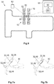
- the passenger accommodation 10 comprises a securing device 32, which is in particular in the Figures 3 and 4 is easily recognizable.
- the securing device 32 comprises a holding element 34 and a counter element 36, the holding element 34 being designed as a projection 38 which is arranged on a safety switch 40.
- the counter element 36 is designed as a belt tongue 42 which is connected to a belt 44 and which forms an opening 45 (see FIG Figure 5 ).
- a belt length adjusting device 46 is provided which fixes the belt 44 in a selectable length.
- the belt 44 forms at its free end a grip section 48 which is designed here as a belt loop. At its end opposite the free end, the belt 44 is fastened to the passenger seat 10 by means of a relief element 50.
- the safety switch 40 is arranged in the thigh padding 30 of the safety bracket 25. With the aid of the safety switch 40, the holding element 34 can be moved axially. In a first end position, the holding element 34 can engage positively in the opening 45 of the belt tongue 42, while in a second end position of the holding element 34 no form-fitting engagement is possible.
- a control unit 52 is integrated in the safety switch 40 and has detection means 55 with which a statement can be made in a redundant and fail-safe manner as to whether the safety device 32 is in the locked state. Furthermore, the control unit 52 has manipulation detection means 53 with which it can be determined in a tamper-proof manner whether the safety device 32 is in the locked state or not.
- the manipulation detection means 53 comprise identification means 54 which are arranged on the counter element 36 and which can be configured, for example, as an RFID chip.
- the control unit 52 of the safety switch 40 can read out the identification means 54 and consequently determine whether the correct counter element 36 has been introduced into the safety device 32.
- the safety switch 40 can determine whether the holding element 34 actually engages in the counter-element 36 in a form-fitting manner. The securing device 32 is only then in the locked state when the holding element 34 engages in the counter-element 36 identified as correct.
- the safety switch 40 forms a structural unit in which the control unit 52 and the stationary components of the safety device 32 are combined.
- the passenger accommodation 10 has a test unit 56, with which it can be checked whether the locking unit 28 is functioning properly or not.
- the amusement ride 14 can also be operated according to the invention without the test unit 56. In this case, the functionality of the locking unit 28 is checked by the employees of the amusement ride 14, in particular on the basis of a visual inspection.
- the amusement ride 14 is equipped with a communication system 58, which is shown in Figure 6 is shown.
- the communication system 58 is in connection with a control unit 60 of the amusement ride 14 as well as with the control unit 52 and the test unit 56.
- the control unit 60 is usually arranged in a building 61 in which an employee responsible for the operation of the amusement ride 14 works.
- a display 63 is arranged in the building 61, which is connected to the control unit 60 and shows all relevant information regarding the status of the amusement ride 12.
- a number of mobile terminals 62 such as wearables, tablets and / or the like, which are used by the employees of the amusement park 14 are used to be connected to the communication system 58.
- Both the control unit 52 and the test unit 56 each have an identifier which can be transmitted to the control unit 60 via the communication system 58 so that the control unit 52 and the test unit 56 can be clearly identified and assigned to the passenger accommodation 10 they monitor .
- the amusement ride 14 is operated in the following way: First, the restraint device 24 is moved into the open position by means of the adjusting device 26, so that a passenger has access to the receiving section 16 of the passenger receptacle 10. After the passenger has sat down in the receiving section 16, the restraint device 24 is placed in the closed position by the adjustment device 26. The adjustment between the open position and the closed position can alternatively also be taken over by an employee of the ride 14 or by the passenger himself. The retaining device 24 is then fixed in the closed position by means of the locking unit 28. The employee of the amusement ride 14 checks that the safety bracket 25 is close to the body and pulls on the safety bracket 25 in order to identify incorrect positions and malfunctions on the safety bracket 25.
- the employee or the passenger pulls the belt 44 to its full length. Now the employee or the passenger puts the belt 44 with the belt tongue 42 into the securing device 32, as shown in FIG Figure 7a is shown. The employee or the passenger can tighten and tighten the belt 44 by gripping the handle section 48.
- the safety switch 40 checks whether the holding element 34 engages in the belt tongue 42 in a form-fitting manner. In addition, the safety switch 40 checks whether the belt tongue 42 is the correct belt tongue 42. At the same time, the safety switch 40 checks itself whether it is working properly. If all the conditions are met, the safety switch 40 generates a status signal, according to which the safety device 32 is in the locked state and the safety switch 40 is functioning correctly.
- the communication system 58 transmits the status signal to the control unit 60 and / or the mobile terminals 62.
- the test unit 56 checks whether the locking unit 28 is functioning correctly.
- the locking unit 28 can be operated hydraulically, so that the test unit 56 can use what is known as an A / B test, for example, to check whether the hydraulic system has leaks and there is a loss of volume.
- the test unit 56 generates a corresponding functionality signal.
- the functionality signal is transmitted to the control unit 60 and / or to the mobile terminals 62 via the communication system 58.
- the A / B test leads in many cases to a discrepancy in the movements of the restraint device 24 and in particular of the safety bracket 25 that is noticeable or visible to the employees and / or passengers If the safety bracket 25 moves slower or faster than the adjacent safety bracket, it comes to a standstill at a different point and / or does not remain in the closed position when an employee of the amusement ride is using the safety bracket pushes close to the body in the closed position. As a result, the employees and / or the passengers can determine without a functionality signal generated by a test unit 56 whether the detection unit 28 is functioning correctly or not. In addition, other irregularities in the passenger receptacle 10 can also be recognized in this way, for example a damaged thigh padding 30.
- the control unit 52 or the safety switch 40 is working correctly and the functionality signal and / or the employees of the amusement ride 14 confirm the functionality of the locking unit 28, the control unit 60 generates a release signal, so that the journey of the relevant vehicle 12 can begin.
- the safety switch 40 sets the holding element 34 into the second end position, as a result of which the belt tongue 42 is released.
- the counter element 36 in this case the belt tongue 42, interacts with the holding element 34 in a self-opening manner. This has the consequence that the belt tongue 42 is pushed out of the securing device 32 as soon as the holding element 34 has been removed from the opening 45 of the belt tongue 42.
- the safety device 32 is then in a position that is shown in Figure 7b is shown.
- the restraint device 24 is then moved into the open position so that the passenger can leave the passenger accommodation 10.
- the safety switch 40 determines that the safety device 32 is not in the locked state and / or the safety switch 40 has a fault determines its functionality
- the safety switch 40 generates a status signal which indicates this situation. This status signal is forwarded to the control unit 60 and to the mobile terminals 62 so that the employees of the amusement park 14 can initiate appropriate countermeasures. Because the safety switch 40 has a unique identifier, the employees have information about which passenger receptacle 10 the safety switch 40 in question is located at. The employees can visit the relevant passenger reception 10 directly.
- the checking unit 56 determines that the fixing unit 28 is no longer working properly, the checking unit 56 outputs a corresponding functionality signal, which is forwarded to the control unit 60 and the mobile terminals 62 by means of the communication system 58.
- the amusement ride 14 can also be operated without the test unit 56. If the A / B test reveals a visible or noticeable deviation of the passenger seat 10 and in particular the locking unit 28 from the target state for the employees, the employee who detects the deviations can inform the employee sitting in building 61, for example by radio. Mobile terminals 62 in the form of smartphones or tablets that communicate with the communication system 58 are not required.
- the restraint device 24 of this passenger receptacle 10 is moved into the closed position by an employee and in the closed position by means of the safety device 32 fixed.
- the control unit 60 can be set up in such a way that the restraint device 24 can no longer be moved out of the closed position until the end of operation.
- the employee sitting in the building 61 can give the control unit 60 a command that the restraint device 24 should no longer be moved out of the closed position until the end of operations.
- the passenger receptacle 10, which has the non-functional locking unit 28, no longer remains accessible to the passengers until the amusement ride 14 closes. After the end of business, the defective locking unit 28 can be exchanged.
Landscapes
- Engineering & Computer Science (AREA)
- Mechanical Engineering (AREA)
- Automation & Control Theory (AREA)
- Lock And Its Accessories (AREA)
- Seats For Vehicles (AREA)
- Pinball Game Machines (AREA)
- Passenger Equipment (AREA)
Priority Applications (2)
| Application Number | Priority Date | Filing Date | Title |
|---|---|---|---|
| HRP20211192TT HRP20211192T1 (hr) | 2017-09-07 | 2018-08-14 | Sklop za prihvat putnika i vozilo sa barem jednim sklopom za prihvat putnika za zabavnu vožnju, postupak upravljanja vozilom i zabavnom vožnjom sa barem jednim takvim vozilom |
| PL18758565T PL3678751T3 (pl) | 2017-09-07 | 2018-08-14 | Gniazdo przyjmujące pasażera i pojazd do urządzenia rekreacyjnego z co najmniej jednym takim gniazdem przyjmującym pasażera, sposób obsługi pojazdu jak również urządzenia rekreacyjnego z co najmniej jednym takim pojazdem |
Applications Claiming Priority (2)
| Application Number | Priority Date | Filing Date | Title |
|---|---|---|---|
| DE102017120645.0A DE102017120645A1 (de) | 2017-09-07 | 2017-09-07 | Fahrgastaufnahme und Fahrzeug mit mindestens einer derartigen Fahrgastaufnahme für ein Fahrgeschäft, Verfahren zum Betreiben eines Fahrzeugs sowie Fahrgeschäft mit mindestens einem solchen Fahrzeug |
| PCT/EP2018/072001 WO2019048194A1 (de) | 2017-09-07 | 2018-08-14 | Fahrgastaufnahme und fahrzeug mit mindestens einer derartigen fahrgastaufnahme für ein fahrgeschäft, verfahren zum betreiben eines fahrzeugs sowie fahrgeschäft mit mindestens einem solchen fahrzeug |
Publications (2)
| Publication Number | Publication Date |
|---|---|
| EP3678751A1 EP3678751A1 (de) | 2020-07-15 |
| EP3678751B1 true EP3678751B1 (de) | 2021-05-26 |
Family
ID=63294205
Family Applications (1)
| Application Number | Title | Priority Date | Filing Date |
|---|---|---|---|
| EP18758565.8A Active EP3678751B1 (de) | 2017-09-07 | 2018-08-14 | Fahrgastaufnahme und fahrzeug mit mindestens einer derartigen fahrgastaufnahme für ein fahrgeschäft, verfahren zum betreiben eines fahrzeugs sowie fahrgeschäft mit mindestens einem solchen fahrzeug |
Country Status (13)
| Country | Link |
|---|---|
| US (1) | US11572033B2 (pl) |
| EP (1) | EP3678751B1 (pl) |
| JP (1) | JP6968985B2 (pl) |
| CN (1) | CN111065443B (pl) |
| AU (1) | AU2018330118B2 (pl) |
| CA (1) | CA3074533C (pl) |
| DE (1) | DE102017120645A1 (pl) |
| DK (1) | DK3678751T3 (pl) |
| ES (1) | ES2880077T3 (pl) |
| HR (1) | HRP20211192T1 (pl) |
| PL (1) | PL3678751T3 (pl) |
| PT (1) | PT3678751T (pl) |
| WO (1) | WO2019048194A1 (pl) |
Families Citing this family (2)
| Publication number | Priority date | Publication date | Assignee | Title |
|---|---|---|---|---|
| CN111841026B (zh) * | 2020-07-30 | 2021-10-15 | 郑州航空工业管理学院 | 一种游乐设备压肩锁紧机构 |
| DE102021210921A1 (de) | 2021-09-29 | 2023-03-30 | Hawe Hydraulik Se | Verriegelungseinheit für eine Fahrgast-Rückhaltevorrichtung, Fahrgeschäft- Fahrgasteinheit mit einer Fahrgast-Rückhaltevorrichtung und einer Verriegelungseinheit sowie Verfahren zur Funktionsprüfung einer Verriegelungseinheit |
Family Cites Families (23)
| Publication number | Priority date | Publication date | Assignee | Title |
|---|---|---|---|---|
| JPH0717600Y2 (ja) | 1988-12-15 | 1995-04-26 | 株式会社トーゴ | 遊戯用乗物の乗客保持装置 |
| US5015933A (en) | 1989-11-15 | 1991-05-14 | Ridewerks, Ltd. | Seat base motion controller |
| US5489212A (en) * | 1990-07-02 | 1996-02-06 | Sega Enterprises Ltd. | Rotating simulator and body holding apparatus therefor |
| US5915286A (en) * | 1998-06-29 | 1999-06-22 | Honeywell Inc. | Safety restraint sensor system |
| US6287211B1 (en) * | 1999-01-11 | 2001-09-11 | Bolliger & Mabillard Ingenieurs Conseils S.A. | Installation for amusement park |
| DE60117236T2 (de) * | 2000-12-13 | 2006-09-14 | Bolliger & Mabillard, Ingènieurs Conseils S.A. | Vorrichtung zum Festhalten der Beine eines Insassen in einem Sitz |
| NL1017724C2 (nl) * | 2001-03-28 | 2002-10-01 | Cobra Beheer Bv | Veiligheidsinrichting voor een kermisattractie. |
| WO2005042308A2 (en) | 2003-10-31 | 2005-05-12 | Disney Enterprises, Inc. | Passenger restraint system |
| ATE488284T1 (de) * | 2004-07-20 | 2010-12-15 | Maurer Friedrich Soehne | Sicherungssystem für personentransportanlagen und fahrgeschäfte |
| EP1721648A1 (en) * | 2005-05-13 | 2006-11-15 | Vekoma Rides Engineering B.V. | Amusement device seat assembly |
| JP5121213B2 (ja) * | 2006-11-22 | 2013-01-16 | タカタ株式会社 | シートベルト装置 |
| CN101795739B (zh) * | 2007-06-29 | 2012-08-08 | 维科马乘骑工程公司 | 娱乐装置座椅组件 |
| DE102007032171B4 (de) | 2007-07-10 | 2009-09-17 | Key Safety Systems, Inc., Sterling Heights | Vorrichtung zur Erkennung des Belegungszustandes eines Fahrzeugsitzes |
| WO2014194969A1 (en) * | 2013-06-04 | 2014-12-11 | Antonio Zamperla S.P.A. | Passenger restraint device for amusement rides |
| JP6261274B2 (ja) | 2013-10-09 | 2018-01-17 | 株式会社ユー・エス・ジェイ | 遊戯用乗物の安全支援装置 |
| US9600999B2 (en) | 2014-05-21 | 2017-03-21 | Universal City Studios Llc | Amusement park element tracking system |
| FR3028625B1 (fr) * | 2014-11-18 | 2018-04-27 | Staubli Faverges | Procede de deconnexion d'un boitier de commande manuelle d'un robot multi-axes et robot pour la mise en oeuvre d'un tel procede |
| KR101826311B1 (ko) * | 2016-06-20 | 2018-02-06 | 도파니 주식회사 | 놀이기구용 개선된 안전바 장치 |
| US11040731B2 (en) * | 2017-04-29 | 2021-06-22 | Universal Studios LLC | Passenger restraint with integrated lighting |
| US12134366B2 (en) * | 2017-12-19 | 2024-11-05 | Universal City Studios Llc | Passive restraint techniques for amusement park rides |
| EP3574967B1 (de) * | 2018-05-30 | 2023-08-16 | Raw Tex International Establishment | Rückhaltevorrichtung zur sicherung eines benutzers in einem fahrgeschäft |
| US11529919B2 (en) * | 2020-01-27 | 2022-12-20 | Universal City Studios Llc | Restraint system for an amusement park attraction |
| US12065099B2 (en) * | 2020-10-05 | 2024-08-20 | Universal City Studios Llc | Remote release, redundant restraint latch |
-
2017
- 2017-09-07 DE DE102017120645.0A patent/DE102017120645A1/de not_active Withdrawn
-
2018
- 2018-08-14 HR HRP20211192TT patent/HRP20211192T1/hr unknown
- 2018-08-14 ES ES18758565T patent/ES2880077T3/es active Active
- 2018-08-14 CN CN201880058485.6A patent/CN111065443B/zh active Active
- 2018-08-14 WO PCT/EP2018/072001 patent/WO2019048194A1/de not_active Ceased
- 2018-08-14 DK DK18758565.8T patent/DK3678751T3/da active
- 2018-08-14 AU AU2018330118A patent/AU2018330118B2/en active Active
- 2018-08-14 PL PL18758565T patent/PL3678751T3/pl unknown
- 2018-08-14 PT PT187585658T patent/PT3678751T/pt unknown
- 2018-08-14 CA CA3074533A patent/CA3074533C/en active Active
- 2018-08-14 EP EP18758565.8A patent/EP3678751B1/de active Active
- 2018-08-14 US US16/644,783 patent/US11572033B2/en active Active
- 2018-08-14 JP JP2020511957A patent/JP6968985B2/ja active Active
Also Published As
| Publication number | Publication date |
|---|---|
| CA3074533C (en) | 2022-08-23 |
| DK3678751T3 (da) | 2021-08-16 |
| DE102017120645A1 (de) | 2019-03-07 |
| US11572033B2 (en) | 2023-02-07 |
| HRP20211192T1 (hr) | 2021-10-29 |
| US20210078528A1 (en) | 2021-03-18 |
| PT3678751T (pt) | 2021-07-06 |
| JP6968985B2 (ja) | 2021-11-24 |
| PL3678751T3 (pl) | 2021-12-13 |
| CA3074533A1 (en) | 2019-03-14 |
| WO2019048194A1 (de) | 2019-03-14 |
| EP3678751A1 (de) | 2020-07-15 |
| CN111065443A (zh) | 2020-04-24 |
| AU2018330118B2 (en) | 2021-04-01 |
| CN111065443B (zh) | 2022-05-10 |
| AU2018330118A1 (en) | 2020-04-23 |
| ES2880077T3 (es) | 2021-11-23 |
| JP2020531188A (ja) | 2020-11-05 |
Similar Documents
| Publication | Publication Date | Title |
|---|---|---|
| EP2352948B1 (de) | Sicherheitsschalter zum erzeugen eines anlagenfreigabesignals in abhängigkeit von der position einer beweglichen schutztür | |
| DE19635741C2 (de) | Entriegelungsvorrichtung für ein Türschloß eines Fahrzeugs | |
| EP1490284A1 (de) | Schacht berwachungssystem f r aufzug | |
| EP4037967B1 (de) | Flugzeugsitzmodul | |
| EP3678751B1 (de) | Fahrgastaufnahme und fahrzeug mit mindestens einer derartigen fahrgastaufnahme für ein fahrgeschäft, verfahren zum betreiben eines fahrzeugs sowie fahrgeschäft mit mindestens einem solchen fahrzeug | |
| EP3951120A1 (de) | Schutztürüberwachungsmodul | |
| EP3575666A1 (de) | Vorrichtung zur absicherung eines gefahrenbereichs einer anlage | |
| EP3638560B1 (de) | Seilbahn mit verriegelungsüberwachung eines fahrzeugs | |
| EP4061757B1 (de) | Einfach rückstellbare elektronische fangvorrichtung | |
| EP1618933B1 (de) | Sicherungssystem für Personentransportanlagen und Fahrgeschäfte | |
| DE102019007216B4 (de) | Türgriffanordnung sowie Verfahren zur Zulässigkeitsprüfung der Bediengeschwindigkeit eines Griffkörpers der Türgriffanordnung | |
| WO2021110553A1 (de) | Verfahren zur übergabe eines transportguts von einem endabschnitt eines fliesslagers an ein entnahmegerät | |
| EP2745205B1 (de) | Verfahren zum betreiben eines steuerungsnetzwerk und steuerungsnetzwerk | |
| WO2019057357A1 (de) | Fahrgastaufnahme für ein fahrgeschäft, verfahren zum betreiben einer derartigen fahrgastaufnahme sowie fahrgeschäft mit einer derartigen fahrgastaufnahme | |
| EP3243980A1 (de) | Verriegelungssystem | |
| DE102024200160A1 (de) | Mobiles Hydrauliksystem mit drahtloser Übertragung von Betriebsdaten und Verfahren zur drahtlosen Übertragung von Betriebsdaten eines mobilen Hydrauliksystems | |
| WO2016008604A1 (de) | Vorrichtung, schalter und verfahren zur aufgabe von gepäckstücken | |
| EP2050706B1 (de) | Festhaltevorrichtung | |
| DE102010011766B4 (de) | Überwachungseinrichtung | |
| EP3474305A1 (de) | Sicherheitsschalter | |
| DE102024118412B3 (de) | Verfahren zum Betreiben eines linearen Transportsystems und lineares Transportsystem | |
| DE102022102068B3 (de) | Prüfstand und verfahren zur absicherung von fahrassistenzsystemen automatisierter kraftfahrzeuge | |
| DE102022116768B4 (de) | Nutzlastträgersystem für ein Luftfahrzeug und Verfahren zur Verwaltung von Nutzlasten eines Luftfahrzeugs | |
| DE102024122811A1 (de) | Elektronische sicherheitsvorrichtung für aufzüge oder hebegeräte und elektronische bremseinrichtung | |
| EP4506912A1 (de) | System zur kontrolle eines zugangs zu einem sicherheitsbereich in einer betriebsumgebung |
Legal Events
| Date | Code | Title | Description |
|---|---|---|---|
| STAA | Information on the status of an ep patent application or granted ep patent |
Free format text: STATUS: UNKNOWN |
|
| STAA | Information on the status of an ep patent application or granted ep patent |
Free format text: STATUS: THE INTERNATIONAL PUBLICATION HAS BEEN MADE |
|
| PUAI | Public reference made under article 153(3) epc to a published international application that has entered the european phase |
Free format text: ORIGINAL CODE: 0009012 |
|
| STAA | Information on the status of an ep patent application or granted ep patent |
Free format text: STATUS: REQUEST FOR EXAMINATION WAS MADE |
|
| 17P | Request for examination filed |
Effective date: 20200210 |
|
| AK | Designated contracting states |
Kind code of ref document: A1 Designated state(s): AL AT BE BG CH CY CZ DE DK EE ES FI FR GB GR HR HU IE IS IT LI LT LU LV MC MK MT NL NO PL PT RO RS SE SI SK SM TR |
|
| AX | Request for extension of the european patent |
Extension state: BA ME |
|
| DAV | Request for validation of the european patent (deleted) | ||
| DAX | Request for extension of the european patent (deleted) | ||
| GRAP | Despatch of communication of intention to grant a patent |
Free format text: ORIGINAL CODE: EPIDOSNIGR1 |
|
| STAA | Information on the status of an ep patent application or granted ep patent |
Free format text: STATUS: GRANT OF PATENT IS INTENDED |
|
| INTG | Intention to grant announced |
Effective date: 20210217 |
|
| RIN1 | Information on inventor provided before grant (corrected) |
Inventor name: BECHERER, MARKUS Inventor name: SCHRADE, STEPHAN |
|
| GRAS | Grant fee paid |
Free format text: ORIGINAL CODE: EPIDOSNIGR3 |
|
| GRAA | (expected) grant |
Free format text: ORIGINAL CODE: 0009210 |
|
| STAA | Information on the status of an ep patent application or granted ep patent |
Free format text: STATUS: THE PATENT HAS BEEN GRANTED |
|
| AK | Designated contracting states |
Kind code of ref document: B1 Designated state(s): AL AT BE BG CH CY CZ DE DK EE ES FI FR GB GR HR HU IE IS IT LI LT LU LV MC MK MT NL NO PL PT RO RS SE SI SK SM TR |
|
| REG | Reference to a national code |
Ref country code: GB Ref legal event code: FG4D Free format text: NOT ENGLISH |
|
| REG | Reference to a national code |
Ref country code: CH Ref legal event code: EP |
|
| REG | Reference to a national code |
Ref country code: AT Ref legal event code: REF Ref document number: 1395632 Country of ref document: AT Kind code of ref document: T Effective date: 20210615 |
|
| REG | Reference to a national code |
Ref country code: DE Ref legal event code: R096 Ref document number: 502018005469 Country of ref document: DE |
|
| REG | Reference to a national code |
Ref country code: IE Ref legal event code: FG4D Free format text: LANGUAGE OF EP DOCUMENT: GERMAN |
|
| REG | Reference to a national code |
Ref country code: PT Ref legal event code: SC4A Ref document number: 3678751 Country of ref document: PT Date of ref document: 20210706 Kind code of ref document: T Free format text: AVAILABILITY OF NATIONAL TRANSLATION Effective date: 20210629 |
|
| REG | Reference to a national code |
Ref country code: HR Ref legal event code: TUEP Ref document number: P20211192T Country of ref document: HR |
|
| REG | Reference to a national code |
Ref country code: FI Ref legal event code: FGE |
|
| REG | Reference to a national code |
Ref country code: NL Ref legal event code: FP |
|
| REG | Reference to a national code |
Ref country code: DK Ref legal event code: T3 Effective date: 20210812 |
|
| REG | Reference to a national code |
Ref country code: SE Ref legal event code: TRGR |
|
| REG | Reference to a national code |
Ref country code: LT Ref legal event code: MG9D |
|
| REG | Reference to a national code |
Ref country code: NO Ref legal event code: T2 Effective date: 20210526 |
|
| REG | Reference to a national code |
Ref country code: HR Ref legal event code: ODRP Ref document number: P20211192T Country of ref document: HR Payment date: 20210804 Year of fee payment: 4 |
|
| PG25 | Lapsed in a contracting state [announced via postgrant information from national office to epo] |
Ref country code: LT Free format text: LAPSE BECAUSE OF FAILURE TO SUBMIT A TRANSLATION OF THE DESCRIPTION OR TO PAY THE FEE WITHIN THE PRESCRIBED TIME-LIMIT Effective date: 20210526 Ref country code: BG Free format text: LAPSE BECAUSE OF FAILURE TO SUBMIT A TRANSLATION OF THE DESCRIPTION OR TO PAY THE FEE WITHIN THE PRESCRIBED TIME-LIMIT Effective date: 20210826 |
|
| REG | Reference to a national code |
Ref country code: HR Ref legal event code: T1PR Ref document number: P20211192 Country of ref document: HR |
|
| REG | Reference to a national code |
Ref country code: ES Ref legal event code: FG2A Ref document number: 2880077 Country of ref document: ES Kind code of ref document: T3 Effective date: 20211123 |
|
| PG25 | Lapsed in a contracting state [announced via postgrant information from national office to epo] |
Ref country code: LV Free format text: LAPSE BECAUSE OF FAILURE TO SUBMIT A TRANSLATION OF THE DESCRIPTION OR TO PAY THE FEE WITHIN THE PRESCRIBED TIME-LIMIT Effective date: 20210526 Ref country code: RS Free format text: LAPSE BECAUSE OF FAILURE TO SUBMIT A TRANSLATION OF THE DESCRIPTION OR TO PAY THE FEE WITHIN THE PRESCRIBED TIME-LIMIT Effective date: 20210526 Ref country code: GR Free format text: LAPSE BECAUSE OF FAILURE TO SUBMIT A TRANSLATION OF THE DESCRIPTION OR TO PAY THE FEE WITHIN THE PRESCRIBED TIME-LIMIT Effective date: 20210827 Ref country code: IS Free format text: LAPSE BECAUSE OF FAILURE TO SUBMIT A TRANSLATION OF THE DESCRIPTION OR TO PAY THE FEE WITHIN THE PRESCRIBED TIME-LIMIT Effective date: 20210926 |
|
| PG25 | Lapsed in a contracting state [announced via postgrant information from national office to epo] |
Ref country code: EE Free format text: LAPSE BECAUSE OF FAILURE TO SUBMIT A TRANSLATION OF THE DESCRIPTION OR TO PAY THE FEE WITHIN THE PRESCRIBED TIME-LIMIT Effective date: 20210526 Ref country code: SK Free format text: LAPSE BECAUSE OF FAILURE TO SUBMIT A TRANSLATION OF THE DESCRIPTION OR TO PAY THE FEE WITHIN THE PRESCRIBED TIME-LIMIT Effective date: 20210526 Ref country code: SM Free format text: LAPSE BECAUSE OF FAILURE TO SUBMIT A TRANSLATION OF THE DESCRIPTION OR TO PAY THE FEE WITHIN THE PRESCRIBED TIME-LIMIT Effective date: 20210526 Ref country code: RO Free format text: LAPSE BECAUSE OF FAILURE TO SUBMIT A TRANSLATION OF THE DESCRIPTION OR TO PAY THE FEE WITHIN THE PRESCRIBED TIME-LIMIT Effective date: 20210526 |
|
| REG | Reference to a national code |
Ref country code: DE Ref legal event code: R097 Ref document number: 502018005469 Country of ref document: DE |
|
| PLBE | No opposition filed within time limit |
Free format text: ORIGINAL CODE: 0009261 |
|
| STAA | Information on the status of an ep patent application or granted ep patent |
Free format text: STATUS: NO OPPOSITION FILED WITHIN TIME LIMIT |
|
| PG25 | Lapsed in a contracting state [announced via postgrant information from national office to epo] |
Ref country code: MC Free format text: LAPSE BECAUSE OF FAILURE TO SUBMIT A TRANSLATION OF THE DESCRIPTION OR TO PAY THE FEE WITHIN THE PRESCRIBED TIME-LIMIT Effective date: 20210526 |
|
| 26N | No opposition filed |
Effective date: 20220301 |
|
| PG25 | Lapsed in a contracting state [announced via postgrant information from national office to epo] |
Ref country code: IS Free format text: LAPSE BECAUSE OF FAILURE TO SUBMIT A TRANSLATION OF THE DESCRIPTION OR TO PAY THE FEE WITHIN THE PRESCRIBED TIME-LIMIT Effective date: 20210926 Ref country code: LU Free format text: LAPSE BECAUSE OF NON-PAYMENT OF DUE FEES Effective date: 20210814 Ref country code: AL Free format text: LAPSE BECAUSE OF FAILURE TO SUBMIT A TRANSLATION OF THE DESCRIPTION OR TO PAY THE FEE WITHIN THE PRESCRIBED TIME-LIMIT Effective date: 20210526 |
|
| REG | Reference to a national code |
Ref country code: DE Ref legal event code: R081 Ref document number: 502018005469 Country of ref document: DE Owner name: MACK RIDES IP GMBH & CO. KG, DE Free format text: FORMER OWNER: MACK RIDES GMBH & CO KG, 79183 WALDKIRCH, DE |
|
| REG | Reference to a national code |
Ref country code: HR Ref legal event code: ODRP Ref document number: P20211192 Country of ref document: HR Payment date: 20220803 Year of fee payment: 5 |
|
| PGFP | Annual fee paid to national office [announced via postgrant information from national office to epo] |
Ref country code: CZ Payment date: 20220803 Year of fee payment: 5 |
|
| P01 | Opt-out of the competence of the unified patent court (upc) registered |
Effective date: 20230427 |
|
| PG25 | Lapsed in a contracting state [announced via postgrant information from national office to epo] |
Ref country code: CY Free format text: LAPSE BECAUSE OF FAILURE TO SUBMIT A TRANSLATION OF THE DESCRIPTION OR TO PAY THE FEE WITHIN THE PRESCRIBED TIME-LIMIT Effective date: 20210526 |
|
| PG25 | Lapsed in a contracting state [announced via postgrant information from national office to epo] |
Ref country code: HU Free format text: LAPSE BECAUSE OF FAILURE TO SUBMIT A TRANSLATION OF THE DESCRIPTION OR TO PAY THE FEE WITHIN THE PRESCRIBED TIME-LIMIT; INVALID AB INITIO Effective date: 20180814 |
|
| REG | Reference to a national code |
Ref country code: HR Ref legal event code: ODRP Ref document number: P20211192 Country of ref document: HR Payment date: 20230801 Year of fee payment: 6 |
|
| PG25 | Lapsed in a contracting state [announced via postgrant information from national office to epo] |
Ref country code: MK Free format text: LAPSE BECAUSE OF FAILURE TO SUBMIT A TRANSLATION OF THE DESCRIPTION OR TO PAY THE FEE WITHIN THE PRESCRIBED TIME-LIMIT Effective date: 20210526 Ref country code: CZ Free format text: LAPSE BECAUSE OF NON-PAYMENT OF DUE FEES Effective date: 20230814 |
|
| REG | Reference to a national code |
Ref country code: HR Ref legal event code: ODRP Ref document number: P20211192 Country of ref document: HR Payment date: 20240808 Year of fee payment: 7 |
|
| PG25 | Lapsed in a contracting state [announced via postgrant information from national office to epo] |
Ref country code: MT Free format text: LAPSE BECAUSE OF FAILURE TO SUBMIT A TRANSLATION OF THE DESCRIPTION OR TO PAY THE FEE WITHIN THE PRESCRIBED TIME-LIMIT Effective date: 20210526 |
|
| REG | Reference to a national code |
Ref country code: HR Ref legal event code: ODRP Ref document number: P20211192 Country of ref document: HR Payment date: 20250808 Year of fee payment: 8 |
|
| PGFP | Annual fee paid to national office [announced via postgrant information from national office to epo] |
Ref country code: NL Payment date: 20250821 Year of fee payment: 8 |
|
| PGFP | Annual fee paid to national office [announced via postgrant information from national office to epo] |
Ref country code: PT Payment date: 20250801 Year of fee payment: 8 Ref country code: FI Payment date: 20250820 Year of fee payment: 8 Ref country code: ES Payment date: 20250917 Year of fee payment: 8 |
|
| PGFP | Annual fee paid to national office [announced via postgrant information from national office to epo] |
Ref country code: DE Payment date: 20250922 Year of fee payment: 8 Ref country code: DK Payment date: 20250821 Year of fee payment: 8 |
|
| PGFP | Annual fee paid to national office [announced via postgrant information from national office to epo] |
Ref country code: NO Payment date: 20250820 Year of fee payment: 8 |
|
| PGFP | Annual fee paid to national office [announced via postgrant information from national office to epo] |
Ref country code: TR Payment date: 20250807 Year of fee payment: 8 Ref country code: PL Payment date: 20250708 Year of fee payment: 8 Ref country code: IT Payment date: 20250829 Year of fee payment: 8 |
|
| PGFP | Annual fee paid to national office [announced via postgrant information from national office to epo] |
Ref country code: BE Payment date: 20250820 Year of fee payment: 8 Ref country code: GB Payment date: 20250822 Year of fee payment: 8 |
|
| PGFP | Annual fee paid to national office [announced via postgrant information from national office to epo] |
Ref country code: HR Payment date: 20250808 Year of fee payment: 8 |
|
| PGFP | Annual fee paid to national office [announced via postgrant information from national office to epo] |
Ref country code: FR Payment date: 20250821 Year of fee payment: 8 Ref country code: AT Payment date: 20250819 Year of fee payment: 8 |
|
| PGFP | Annual fee paid to national office [announced via postgrant information from national office to epo] |
Ref country code: CH Payment date: 20250901 Year of fee payment: 8 Ref country code: SE Payment date: 20250821 Year of fee payment: 8 |
|
| PGFP | Annual fee paid to national office [announced via postgrant information from national office to epo] |
Ref country code: IE Payment date: 20250821 Year of fee payment: 8 |