EP3677530A1 - Doppelwandiger hochtemperaturschmelzsalzaufbewahrungstank mit interstitiellem raum - Google Patents
Doppelwandiger hochtemperaturschmelzsalzaufbewahrungstank mit interstitiellem raum Download PDFInfo
- Publication number
- EP3677530A1 EP3677530A1 EP18851663.7A EP18851663A EP3677530A1 EP 3677530 A1 EP3677530 A1 EP 3677530A1 EP 18851663 A EP18851663 A EP 18851663A EP 3677530 A1 EP3677530 A1 EP 3677530A1
- Authority
- EP
- European Patent Office
- Prior art keywords
- tank
- molten salt
- layer
- double
- floor
- Prior art date
- Legal status (The legal status is an assumption and is not a legal conclusion. Google has not performed a legal analysis and makes no representation as to the accuracy of the status listed.)
- Granted
Links
Images
Classifications
-
- F—MECHANICAL ENGINEERING; LIGHTING; HEATING; WEAPONS; BLASTING
- F28—HEAT EXCHANGE IN GENERAL
- F28D—HEAT-EXCHANGE APPARATUS, NOT PROVIDED FOR IN ANOTHER SUBCLASS, IN WHICH THE HEAT-EXCHANGE MEDIA DO NOT COME INTO DIRECT CONTACT
- F28D20/00—Heat storage plants or apparatus in general; Regenerative heat-exchange apparatus not covered by groups F28D17/00 or F28D19/00
- F28D20/0034—Heat storage plants or apparatus in general; Regenerative heat-exchange apparatus not covered by groups F28D17/00 or F28D19/00 using liquid heat storage material
-
- B—PERFORMING OPERATIONS; TRANSPORTING
- B65—CONVEYING; PACKING; STORING; HANDLING THIN OR FILAMENTARY MATERIAL
- B65D—CONTAINERS FOR STORAGE OR TRANSPORT OF ARTICLES OR MATERIALS, e.g. BAGS, BARRELS, BOTTLES, BOXES, CANS, CARTONS, CRATES, DRUMS, JARS, TANKS, HOPPERS, FORWARDING CONTAINERS; ACCESSORIES, CLOSURES, OR FITTINGS THEREFOR; PACKAGING ELEMENTS; PACKAGES
- B65D88/00—Large containers
- B65D88/74—Large containers having means for heating, cooling, aerating or other conditioning of contents
- B65D88/744—Large containers having means for heating, cooling, aerating or other conditioning of contents heating or cooling through the walls or internal parts of the container, e.g. circulation of fluid inside the walls
-
- B—PERFORMING OPERATIONS; TRANSPORTING
- B65—CONVEYING; PACKING; STORING; HANDLING THIN OR FILAMENTARY MATERIAL
- B65D—CONTAINERS FOR STORAGE OR TRANSPORT OF ARTICLES OR MATERIALS, e.g. BAGS, BARRELS, BOTTLES, BOXES, CANS, CARTONS, CRATES, DRUMS, JARS, TANKS, HOPPERS, FORWARDING CONTAINERS; ACCESSORIES, CLOSURES, OR FITTINGS THEREFOR; PACKAGING ELEMENTS; PACKAGES
- B65D88/00—Large containers
- B65D88/74—Large containers having means for heating, cooling, aerating or other conditioning of contents
- B65D88/745—Large containers having means for heating, cooling, aerating or other conditioning of contents blowing or injecting heating, cooling or other conditioning fluid inside the container
-
- B—PERFORMING OPERATIONS; TRANSPORTING
- B65—CONVEYING; PACKING; STORING; HANDLING THIN OR FILAMENTARY MATERIAL
- B65D—CONTAINERS FOR STORAGE OR TRANSPORT OF ARTICLES OR MATERIALS, e.g. BAGS, BARRELS, BOTTLES, BOXES, CANS, CARTONS, CRATES, DRUMS, JARS, TANKS, HOPPERS, FORWARDING CONTAINERS; ACCESSORIES, CLOSURES, OR FITTINGS THEREFOR; PACKAGING ELEMENTS; PACKAGES
- B65D90/00—Component parts, details or accessories for large containers
- B65D90/48—Arrangements of indicating or measuring devices
-
- B—PERFORMING OPERATIONS; TRANSPORTING
- B65—CONVEYING; PACKING; STORING; HANDLING THIN OR FILAMENTARY MATERIAL
- B65D—CONTAINERS FOR STORAGE OR TRANSPORT OF ARTICLES OR MATERIALS, e.g. BAGS, BARRELS, BOTTLES, BOXES, CANS, CARTONS, CRATES, DRUMS, JARS, TANKS, HOPPERS, FORWARDING CONTAINERS; ACCESSORIES, CLOSURES, OR FITTINGS THEREFOR; PACKAGING ELEMENTS; PACKAGES
- B65D90/00—Component parts, details or accessories for large containers
- B65D90/02—Wall construction
- B65D90/028—Wall construction hollow-walled, e.g. double-walled with spacers
-
- B—PERFORMING OPERATIONS; TRANSPORTING
- B65—CONVEYING; PACKING; STORING; HANDLING THIN OR FILAMENTARY MATERIAL
- B65D—CONTAINERS FOR STORAGE OR TRANSPORT OF ARTICLES OR MATERIALS, e.g. BAGS, BARRELS, BOTTLES, BOXES, CANS, CARTONS, CRATES, DRUMS, JARS, TANKS, HOPPERS, FORWARDING CONTAINERS; ACCESSORIES, CLOSURES, OR FITTINGS THEREFOR; PACKAGING ELEMENTS; PACKAGES
- B65D90/00—Component parts, details or accessories for large containers
- B65D90/48—Arrangements of indicating or measuring devices
- B65D90/50—Arrangements of indicating or measuring devices of leakage-indicating devices
- B65D90/501—Arrangements of indicating or measuring devices of leakage-indicating devices comprising hollow spaces within walls
-
- F—MECHANICAL ENGINEERING; LIGHTING; HEATING; WEAPONS; BLASTING
- F28—HEAT EXCHANGE IN GENERAL
- F28D—HEAT-EXCHANGE APPARATUS, NOT PROVIDED FOR IN ANOTHER SUBCLASS, IN WHICH THE HEAT-EXCHANGE MEDIA DO NOT COME INTO DIRECT CONTACT
- F28D20/00—Heat storage plants or apparatus in general; Regenerative heat-exchange apparatus not covered by groups F28D17/00 or F28D19/00
- F28D20/0034—Heat storage plants or apparatus in general; Regenerative heat-exchange apparatus not covered by groups F28D17/00 or F28D19/00 using liquid heat storage material
- F28D2020/0047—Heat storage plants or apparatus in general; Regenerative heat-exchange apparatus not covered by groups F28D17/00 or F28D19/00 using liquid heat storage material using molten salts or liquid metals
-
- F—MECHANICAL ENGINEERING; LIGHTING; HEATING; WEAPONS; BLASTING
- F28—HEAT EXCHANGE IN GENERAL
- F28F—DETAILS OF HEAT-EXCHANGE AND HEAT-TRANSFER APPARATUS, OF GENERAL APPLICATION
- F28F2270/00—Thermal insulation; Thermal decoupling
-
- Y—GENERAL TAGGING OF NEW TECHNOLOGICAL DEVELOPMENTS; GENERAL TAGGING OF CROSS-SECTIONAL TECHNOLOGIES SPANNING OVER SEVERAL SECTIONS OF THE IPC; TECHNICAL SUBJECTS COVERED BY FORMER USPC CROSS-REFERENCE ART COLLECTIONS [XRACs] AND DIGESTS
- Y02—TECHNOLOGIES OR APPLICATIONS FOR MITIGATION OR ADAPTATION AGAINST CLIMATE CHANGE
- Y02E—REDUCTION OF GREENHOUSE GAS [GHG] EMISSIONS, RELATED TO ENERGY GENERATION, TRANSMISSION OR DISTRIBUTION
- Y02E60/00—Enabling technologies; Technologies with a potential or indirect contribution to GHG emissions mitigation
- Y02E60/14—Thermal energy storage
Definitions
- the invention belongs to the technical field of solar thermal devices, and in particular relates to a double-layer jacket high-temperature molten salt storage tank.
- Solar thermal power generation is an important source of clean energy.
- solar thermal power generation using molten salt as a thermal storage medium is a generally recognized scheme in the world.
- Molten salt can not only be used as an intermediate thermal energy carrier, but also can be stored in molten salt storage tanks to ensure continuous and stable output of electric energy without sunlight at night.
- solar thermal power generation is a grid-friendly power supply and solves common power application problems faced by new energy sources.
- High-temperature molten salt storage tanks play a key role in energy storage for power generation. Whether the insulation effect of molten salt storage tanks is good and whether devices are safe and reliable directly affect the stable operation of power generation systems and the economic benefit of power stations.
- the existing high-temperature molten salt storage tanks generally adopt the structural form of conventional cylindrical stainless steel storage tanks with external insulation materials, which mainly have the following technical problems: 1. the insulation materials are arranged on the outside of tank bodies and are only protected by insulation aluminum sheets or iron sheets, so the high-temperature molten salt storage tanks are vulnerable to rain, snow and strong winds and inevitably need regular maintenance; 2. the outside of the tank bodies is covered with insulation materials, thus deformation of the tank bodies and weld leakage cannot be effectively observed and detected in time; 3. preheating of the tank bodies is difficult and takes a long time, and it is difficult to achieve uniform temperature in all parts of the tank bodies; 4.
- tank roofs and tank walls due to uneven heating of tank roofs and tank walls, joints between the tank roofs and the tank walls have high differential temperature stress and are easy to be destroyed; 5. the working temperature of the tank roofs is close to that of high-temperature molten salt, which makes it difficult to design and manufacture; and 6. tank floor insulation materials are directly arranged on tank foundations, and additional protection is required to avoid the influence of rainwater; in addition, cold air pipes have to pass through or bypass tank foundation beams, thus the tank foundations have the disadvantages of difficult design, complicated structures and high construction cost.
- the purpose of the invention is to provide a double-layer jacket high-temperature molten salt storage tank which has a long service life, can effectively prevent direct leakage of molten salt, can provide a release space for thermal deformation of the tank body, and facilitate preheating of the tank body.
- a double-layer jacket high-temperature molten salt storage tank comprising a tank body, a tank roof and a tank floor, and characterized in that the tank body consists of an inner tank and an outer tank, a jacket space is formed between the inner tank and the outer tank, a tank insulating layer is arranged at the inner side of the outer tank in the jacket space, and an air layer is reserved between the tank insulating layer and the inner tank.
- the double-layer jacket high-temperature molten salt storage tank of the invention is characterized in that the inner tank has a stainless steel structure that is resistant to high temperature and corrosion and is subject to static pressure of molten salt, and the outer tank is not in contact with the molten salt, and is thus not subject to the static pressure of the molten salt.
- the double-layer jacket high-temperature molten salt storage tank of the invention is characterized in that the tank insulating layer arranged at the inner side of the outer tank is made of a light insulation fiber product.
- the double-layer jacket high-temperature molten salt storage tank of the invention is characterized in that the top of the inner tank has no tank roof, and the inner tank freely expands outward with increasing temperature.
- the double-layer jacket high-temperature molten salt storage tank of the invention is characterized in that a molten salt storage tank level detector, a temperature detector and a monitor for monitoring deformation of the inner tank and weld leakage are arranged in the air layer of the jacket space.
- the double-layer jacket high-temperature molten salt storage tank of the invention is characterized in that an inner tank roof plate is arranged on the top of the inner tank, a refractory fiber layer is laid on the inner tank roof plate, one end of the tank roof is connected with an upper end of the tank body, and the tank roof is connected with the inner tank roof plate through a hanger rod.
- the double-layer jacket high-temperature molten salt storage tank of the invention is characterized in that the tank floor consists of an inner tank floor and an outer tank floor, a tank floor insulating layer is arranged between the inner tank floor and the outer tank floor, and the outer tank floor is mounted on a reinforced concrete foundation.
- the double-layer jacket high-temperature molten salt storage tank of the invention is characterized in that a cold air pipe of the tank floor is arranged on the outer tank floor, and the cold air pipe is arranged at a certain distance from the reinforced concrete foundation.
- the tank body of the invention adopts a double-layer structure and a composite insulation structure is formed by using the insulating layer and the air layer, thereby avoiding the influence of high temperature on the outer tank and enabling the inner tank to expand freely without being restricted by the insulating layer.
- Insulation materials of the tank roof, a tank wall and the tank floor are arranged in an outer steel shell, thus effectively avoiding the influence of exposure of existing insulation materials on the performance of the insulation materials and prolonging the service life of the insulation materials.
- the invention has the following technical effects:
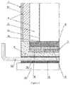
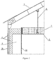
- FIG. 1 and Figure 2 are structural diagrams of the invention.
- 1 -tank body 1a-inner tank, 1b-outer tank, 2-tank roof, 3-tank floor, 3a-inner tank floor, 3b-outer tank floor, 4-tank insulating layer, 5-air layer, 6-inner tank roof plate, 7-refractory fiber layer, 8-hanger rod, 9-tank floor insulating layer, 10-reinforced concrete foundation, 11-cold air pipe.
- a double-layer jacket high-temperature molten salt storage tank comprises a tank body 1, a tank roof 2 and a tank floor 3.
- the tank body 1 consists of an inner tank 1a and an outer tank 1b, an inner tank roof plate 6 is arranged on the top of the inner tank 1a, a refractory fiber layer 7 is laid on the inner tank roof plate 6, one end of the tank roof 2 is connected with an upper end of the tank body 1, and the tank roof 2 is connected with the inner tank roof plate 6 through a hanger rod 8.
- the inner tank 1a has a stainless steel structure that is resistant to high temperature and corrosion and is subject to static pressure of molten salt; and the outer tank 1b is not in contact with the molten salt, is not subject to the static pressure of the molten salt, has no need for high temperature resistance and corrosion resistance, can be made of cheap ordinary carbon steel and is exposed to ambient environment.
- a jacket space is formed between the inner tank 1a and the outer tank 1b, a tank insulating layer 4 is arranged at the inner side of the outer tank 1b in the jacket space, and an air layer 5 is reserved between the tank insulating layer 4 and the inner tank 1a.
- the tank insulating layer 4 arranged at the inner side of the outer tank 1b is made of a light insulation fiber product such as ceramic fiber product, and has good insulation performance.
- the arrangement of the tank insulating layer avoids heat loss of the storage tank and meets the process requirements of heat storage and energy storage. Meanwhile, the tank insulating layer isolates high temperature, so that the outer tank does not need to withstand high temperature and is not in contact with molten salt. Therefore, the outer tank can be made of ordinary carbon steel.
- the top of the inner tank 1a has no tank roof 2, and the inner tank 1a can freely expand outward with increasing temperature.
- a molten salt storage tank level detector, a temperature detector and a monitor for monitoring deformation of the inner tank 1a and weld leakage are arranged in the air layer 5 of the jacket space.
- the tank floor 3 consists of an inner tank floor 3a and an outer tank floor 3b, a tank floor insulating layer 9 is arranged between the inner tank floor 3a and the outer tank floor 3b, and the outer tank floor 3b is mounted on a reinforced concrete foundation 10.
- a cold air pipe 11 of the tank floor 3 is arranged on the outer tank floor 3b, and the cold air pipe 11 is arranged at a certain distance from the reinforced concrete foundation 10.
Landscapes
- Engineering & Computer Science (AREA)
- Mechanical Engineering (AREA)
- Physics & Mathematics (AREA)
- Thermal Sciences (AREA)
- General Engineering & Computer Science (AREA)
- Filling Or Discharging Of Gas Storage Vessels (AREA)
Applications Claiming Priority (2)
| Application Number | Priority Date | Filing Date | Title |
|---|---|---|---|
| CN201710776816.7A CN107380780B (zh) | 2017-08-31 | 2017-08-31 | 一种双层夹套高温熔盐储罐 |
| PCT/CN2018/102148 WO2019042222A1 (zh) | 2017-08-31 | 2018-08-24 | 一种双层夹套高温熔盐储罐 |
Publications (4)
| Publication Number | Publication Date |
|---|---|
| EP3677530A1 true EP3677530A1 (de) | 2020-07-08 |
| EP3677530A4 EP3677530A4 (de) | 2021-08-25 |
| EP3677530B1 EP3677530B1 (de) | 2024-07-24 |
| EP3677530C0 EP3677530C0 (de) | 2024-07-24 |
Family
ID=60348360
Family Applications (1)
| Application Number | Title | Priority Date | Filing Date |
|---|---|---|---|
| EP18851663.7A Active EP3677530B1 (de) | 2017-08-31 | 2018-08-24 | Doppelwandiger hochtemperaturschmelzsalzaufbewahrungstank mit interstitiellem raum |
Country Status (4)
| Country | Link |
|---|---|
| EP (1) | EP3677530B1 (de) |
| CN (1) | CN107380780B (de) |
| ES (1) | ES2984948T3 (de) |
| WO (1) | WO2019042222A1 (de) |
Cited By (1)
| Publication number | Priority date | Publication date | Assignee | Title |
|---|---|---|---|---|
| WO2024031142A1 (en) * | 2022-08-09 | 2024-02-15 | Vast Solar Pty Ltd | Thermal energy storage system |
Families Citing this family (19)
| Publication number | Priority date | Publication date | Assignee | Title |
|---|---|---|---|---|
| CN107380780B (zh) * | 2017-08-31 | 2023-06-20 | 中国成达工程有限公司 | 一种双层夹套高温熔盐储罐 |
| CN108627116B (zh) * | 2018-05-31 | 2020-04-10 | 中国石油天然气集团有限公司 | 带保温层储罐的三维激光扫描变形检测装置及方法 |
| CN109095020A (zh) * | 2018-08-15 | 2018-12-28 | 中国成达工程有限公司 | 一种高温储罐基础冷却系统 |
| CN110118444A (zh) * | 2019-01-23 | 2019-08-13 | 兰州交通大学 | 太阳能折流结构集装箱式高温固体储热装置 |
| CN109781346A (zh) * | 2019-01-30 | 2019-05-21 | 青岛鸿瑞电力工程咨询有限公司 | 一种高温熔盐罐泄露实时在线监测装置及检测方法 |
| CN111238917A (zh) * | 2020-03-19 | 2020-06-05 | 上海卓光仪器科技有限公司 | 一种高压消解罐 |
| CN111442136B (zh) * | 2020-03-30 | 2024-06-18 | 中国成达工程有限公司 | 高温熔盐罐的内外管道应力补偿结构及方法 |
| CN111397417A (zh) * | 2020-04-16 | 2020-07-10 | 哈尔滨汽轮机厂辅机工程有限公司 | 一种用于850℃高温沙子的储热罐 |
| CN113819663B (zh) * | 2020-06-20 | 2025-03-14 | 蓝星(北京)化工机械有限公司 | 可自由伸缩释放热应力的高温熔盐储罐 |
| CN113819662B (zh) * | 2020-06-20 | 2025-01-28 | 蓝星(北京)化工机械有限公司 | 具有泄漏检测及热补偿装置的熔盐储罐 |
| CN113184400B (zh) * | 2021-04-27 | 2022-07-05 | 中国电建集团江西装备有限公司 | 一种具有防泄漏结构的熔盐储罐及其检漏方法 |
| CN113184395A (zh) * | 2021-04-29 | 2021-07-30 | 中国电建集团江西装备有限公司 | 一种双层夹套高温熔盐储罐及其使用方法 |
| CN114011100B (zh) * | 2021-12-03 | 2022-12-27 | 扬州大学 | 一种刮板薄膜蒸发器用两相组合式加热夹套及制作方法 |
| CN116280764B (zh) * | 2023-05-25 | 2023-08-15 | 蓝星(北京)化工机械有限公司 | 带气囊的双层高温熔盐储罐 |
| CN117184677B (zh) * | 2023-09-13 | 2025-06-17 | 北京民利储能技术有限公司 | 一种防泄漏的储能用熔盐储罐 |
| CN118183091A (zh) * | 2024-05-07 | 2024-06-14 | 天华化工机械及自动化研究设计院有限公司 | 一种大型双层熔融盐立式储罐 |
| CN118408408B (zh) * | 2024-06-06 | 2025-09-05 | 太原理工大学 | 一种用于均化熔盐储热罐地基温度分布的热管冷却系统 |
| CN119086127B (zh) * | 2024-09-03 | 2025-11-18 | 中国科学院电工研究所 | 一种熔盐储罐测试装置以及熔盐储罐测试方法 |
| CN118953899B (zh) * | 2024-10-12 | 2025-01-24 | 上海联和日环能源科技有限公司 | 一种熔盐储罐、熔盐储能系统及其温度控制方法 |
Family Cites Families (25)
| Publication number | Priority date | Publication date | Assignee | Title |
|---|---|---|---|---|
| DE3117966A1 (de) * | 1981-05-07 | 1982-11-25 | Kaefer International GmbH, 5090 Leverkusen | "flachbodentank zur lagerung von fluessiggas" |
| JPH0790667A (ja) * | 1993-09-25 | 1995-04-04 | Tanaka Kikinzoku Kogyo Kk | 溶融塩用ガス拡散電極及びそれを用いた溶融塩電解槽 |
| NO178554C (no) * | 1994-03-28 | 1996-04-17 | Kvaerner Moss Tech As | Termisk isolert tank og veggmodul-element til bruk ved oppbygging av tanken |
| JPH10146273A (ja) * | 1996-11-19 | 1998-06-02 | Hitachi Home Tec Ltd | 炊飯器 |
| JP2002241148A (ja) * | 2001-02-09 | 2002-08-28 | Fukuchi Kenso:Kk | 多層断熱ガラス |
| JP4198434B2 (ja) * | 2002-10-09 | 2008-12-17 | 勝敏 小野 | 金属チタンの製錬方法 |
| JP2009270379A (ja) * | 2008-05-09 | 2009-11-19 | Akua Tekku:Kk | 建築物の外表面構造及び建築物の外表面塗装方法 |
| MX2009014106A (es) * | 2009-12-18 | 2011-06-27 | Monterrey Inst Tecnologico Y De Estudios Superiores De | Tanque termico de sales fundidas con vacio anidado. |
| CN102384822A (zh) * | 2010-09-06 | 2012-03-21 | 贵州金赤化工有限责任公司 | 用于监测尿素高压设备检漏管的检测装置 |
| CN102020482B (zh) * | 2010-11-13 | 2013-10-16 | 西安超码科技有限公司 | 一种大型电阻式双真空气相沉炭装置 |
| CN202346221U (zh) * | 2011-12-09 | 2012-07-25 | 长沙锅炉厂有限责任公司 | 一种用于存储太阳能热发电蓄热介质的高温内绝热储罐 |
| CN102582981A (zh) * | 2012-02-29 | 2012-07-18 | 江苏太阳宝新能源有限公司 | 太阳能光热发电高温熔盐储罐保温结构及其制备方法 |
| JP5998616B2 (ja) * | 2012-04-26 | 2016-09-28 | 株式会社Ihi | 独立ライナユニット及びタンクの建設方法 |
| CN202784409U (zh) * | 2012-08-09 | 2013-03-13 | 哈尔滨汽轮机厂辅机工程有限公司 | 用于槽式光热电站的熔盐储罐及储罐保温结构 |
| CN204507741U (zh) * | 2015-03-16 | 2015-07-29 | 蓝星(北京)化工机械有限公司 | 高温熔盐储罐的保温装置 |
| CN204678717U (zh) * | 2015-04-06 | 2015-09-30 | 天津滨海储能技术有限公司 | 一种高温熔盐储能装置 |
| DE102015011870A1 (de) * | 2015-09-10 | 2017-03-16 | Linde Aktiengesellschaft | Fixierung von Flachbodentanks für Salzschmelzen auf Schüttungen |
| CN105115675A (zh) * | 2015-09-11 | 2015-12-02 | 中国石油化工股份有限公司 | 一种埋地双层油罐夹层泄漏检测系统 |
| CN105346878B (zh) * | 2015-11-30 | 2017-12-01 | 北京京金吾高科技股份有限公司 | 一种滤毒危险品封闭式安全防爆储运装置 |
| CN205240395U (zh) * | 2015-12-14 | 2016-05-18 | 沈阳骅飞管业有限公司 | 具有中空夹层的储油罐 |
| CN205931952U (zh) * | 2016-06-24 | 2017-02-08 | 中冶南方工程技术有限公司 | 基于空气层保温的大型高温储罐的保温结构 |
| CN205837674U (zh) * | 2016-07-11 | 2016-12-28 | 江苏爱能森科技有限公司 | 一种光热发电保温系统 |
| CN206407412U (zh) * | 2016-12-26 | 2017-08-15 | 蓝星(北京)化工机械有限公司 | 一种用于太阳能光热发电系统的高温熔盐储罐装置 |
| CN107380780B (zh) * | 2017-08-31 | 2023-06-20 | 中国成达工程有限公司 | 一种双层夹套高温熔盐储罐 |
| CN207226152U (zh) * | 2017-08-31 | 2018-04-13 | 中国成达工程有限公司 | 一种双层夹套高温熔盐储罐 |
-
2017
- 2017-08-31 CN CN201710776816.7A patent/CN107380780B/zh active Active
-
2018
- 2018-08-24 ES ES18851663T patent/ES2984948T3/es active Active
- 2018-08-24 WO PCT/CN2018/102148 patent/WO2019042222A1/zh not_active Ceased
- 2018-08-24 EP EP18851663.7A patent/EP3677530B1/de active Active
Cited By (1)
| Publication number | Priority date | Publication date | Assignee | Title |
|---|---|---|---|---|
| WO2024031142A1 (en) * | 2022-08-09 | 2024-02-15 | Vast Solar Pty Ltd | Thermal energy storage system |
Also Published As
| Publication number | Publication date |
|---|---|
| WO2019042222A1 (zh) | 2019-03-07 |
| ES2984948T3 (es) | 2024-10-31 |
| CN107380780B (zh) | 2023-06-20 |
| EP3677530B1 (de) | 2024-07-24 |
| CN107380780A (zh) | 2017-11-24 |
| EP3677530C0 (de) | 2024-07-24 |
| EP3677530A4 (de) | 2021-08-25 |
Similar Documents
| Publication | Publication Date | Title |
|---|---|---|
| EP3677530B1 (de) | Doppelwandiger hochtemperaturschmelzsalzaufbewahrungstank mit interstitiellem raum | |
| CN113819663B (zh) | 可自由伸缩释放热应力的高温熔盐储罐 | |
| CN107328120A (zh) | 一种高、低温熔盐的储能换热系统 | |
| CN101413620A (zh) | 钢套钢真空高温蒸汽预制直埋保温管及其生产方法 | |
| CN207226153U (zh) | 一种双层薄膜高温熔盐储罐 | |
| CN207226152U (zh) | 一种双层夹套高温熔盐储罐 | |
| CN207365478U (zh) | 一种高、低温熔盐的储能换热系统 | |
| CN106958689B (zh) | 热水管道管廊无补偿敷设方法 | |
| CN212006869U (zh) | 一种围裙状支撑式熔盐储罐 | |
| CN204879448U (zh) | 一种利用太阳能加热空气的天然气管道防冻胀装置 | |
| CN111174620B (zh) | 一种围裙状支撑式熔盐储罐 | |
| CN112460338A (zh) | 一种用于塔式锅炉穿墙管的密封结构 | |
| CN214093356U (zh) | 一种用于塔式锅炉穿墙管的密封结构 | |
| CN209944783U (zh) | 一种塔式光热电站吸热器用高温隔热防护结构 | |
| CN116717923A (zh) | 熔盐塔式吸热器及其工作方法、流程耦合控制方法 | |
| CN202734262U (zh) | 壁挂式光波加热双层胆太阳能热水器 | |
| CN217866105U (zh) | 一种附着热障涂层的高温熔盐储罐 | |
| CN207379343U (zh) | 高温熔盐蓄能池 | |
| CN222231389U (zh) | 高温熔盐用球形储罐 | |
| CN221570543U (zh) | 用于金属膨胀节的密封结构 | |
| CN105782592A (zh) | 输送原油用双层隔热管及泄漏监测方法 | |
| CN222544408U (zh) | 一种便捷式热轧加热炉立柱的预制构件 | |
| CN201583016U (zh) | 玻璃管熔封真空循环集热元件太阳集热装置 | |
| CN120970338A (zh) | 一种适用于双罐熔盐储热系统的熔盐储热装置 | |
| CN212080851U (zh) | 一种具有侧板保温结构的poc型煤气柜 |
Legal Events
| Date | Code | Title | Description |
|---|---|---|---|
| STAA | Information on the status of an ep patent application or granted ep patent |
Free format text: STATUS: THE INTERNATIONAL PUBLICATION HAS BEEN MADE |
|
| PUAI | Public reference made under article 153(3) epc to a published international application that has entered the european phase |
Free format text: ORIGINAL CODE: 0009012 |
|
| STAA | Information on the status of an ep patent application or granted ep patent |
Free format text: STATUS: REQUEST FOR EXAMINATION WAS MADE |
|
| 17P | Request for examination filed |
Effective date: 20200227 |
|
| AK | Designated contracting states |
Kind code of ref document: A1 Designated state(s): AL AT BE BG CH CY CZ DE DK EE ES FI FR GB GR HR HU IE IS IT LI LT LU LV MC MK MT NL NO PL PT RO RS SE SI SK SM TR |
|
| AX | Request for extension of the european patent |
Extension state: BA ME |
|
| RIN1 | Information on inventor provided before grant (corrected) |
Inventor name: SONG, SHIXIONG Inventor name: PENG, XIFENG Inventor name: ZENG, YUFENG Inventor name: HUANG, ZEMAO Inventor name: YOU, SILIANG Inventor name: LIU, BIN Inventor name: WANG, ZHITUO Inventor name: WANG, REN Inventor name: LI, KUI Inventor name: CHEN, YUDA Inventor name: WANG, BIN Inventor name: LIU, RENTAO Inventor name: WANG, RUI Inventor name: TANG, JIN |
|
| RIN1 | Information on inventor provided before grant (corrected) |
Inventor name: PENG, XIFENG Inventor name: LIU, RENTAO Inventor name: WANG, BIN Inventor name: LIU, BIN Inventor name: LI, KUI Inventor name: WANG, ZHITUO Inventor name: WANG, REN Inventor name: ZENG, YUFENG Inventor name: YOU, SILIANG Inventor name: HUANG, ZEMAO Inventor name: SONG, SHIXIONG Inventor name: CHEN, YUDA Inventor name: TANG, JIN Inventor name: WANG, RUI |
|
| DAV | Request for validation of the european patent (deleted) | ||
| DAX | Request for extension of the european patent (deleted) | ||
| RIC1 | Information provided on ipc code assigned before grant |
Ipc: F28D 20/00 20060101AFI20210419BHEP Ipc: B65D 90/02 20190101ALN20210419BHEP Ipc: B65D 90/50 20190101ALN20210419BHEP |
|
| REG | Reference to a national code |
Ref country code: DE Ref legal event code: R079 Free format text: PREVIOUS MAIN CLASS: B65D0090020000 Ipc: F28D0020000000 Ref country code: DE Ref legal event code: R079 Ref document number: 602018072279 Country of ref document: DE Free format text: PREVIOUS MAIN CLASS: B65D0090020000 Ipc: F28D0020000000 |
|
| A4 | Supplementary search report drawn up and despatched |
Effective date: 20210726 |
|
| RIC1 | Information provided on ipc code assigned before grant |
Ipc: F28D 20/00 20060101AFI20210720BHEP Ipc: B65D 90/02 20190101ALN20210720BHEP Ipc: B65D 90/50 20190101ALN20210720BHEP |
|
| STAA | Information on the status of an ep patent application or granted ep patent |
Free format text: STATUS: EXAMINATION IS IN PROGRESS |
|
| 17Q | First examination report despatched |
Effective date: 20230403 |
|
| GRAP | Despatch of communication of intention to grant a patent |
Free format text: ORIGINAL CODE: EPIDOSNIGR1 |
|
| STAA | Information on the status of an ep patent application or granted ep patent |
Free format text: STATUS: GRANT OF PATENT IS INTENDED |
|
| RIC1 | Information provided on ipc code assigned before grant |
Ipc: B65D 90/501 20190101ALN20240229BHEP Ipc: B65D 90/02 20190101ALN20240229BHEP Ipc: F28D 20/00 20060101AFI20240229BHEP |
|
| INTG | Intention to grant announced |
Effective date: 20240319 |
|
| GRAS | Grant fee paid |
Free format text: ORIGINAL CODE: EPIDOSNIGR3 |
|
| GRAA | (expected) grant |
Free format text: ORIGINAL CODE: 0009210 |
|
| STAA | Information on the status of an ep patent application or granted ep patent |
Free format text: STATUS: THE PATENT HAS BEEN GRANTED |
|
| AK | Designated contracting states |
Kind code of ref document: B1 Designated state(s): AL AT BE BG CH CY CZ DE DK EE ES FI FR GB GR HR HU IE IS IT LI LT LU LV MC MK MT NL NO PL PT RO RS SE SI SK SM TR |
|
| REG | Reference to a national code |
Ref country code: GB Ref legal event code: FG4D |
|
| REG | Reference to a national code |
Ref country code: CH Ref legal event code: EP |
|
| REG | Reference to a national code |
Ref country code: IE Ref legal event code: FG4D Ref country code: DE Ref legal event code: R096 Ref document number: 602018072279 Country of ref document: DE |
|
| U01 | Request for unitary effect filed |
Effective date: 20240820 |
|
| U07 | Unitary effect registered |
Designated state(s): AT BE BG DE DK EE FI FR IT LT LU LV MT NL PT SE SI Effective date: 20240829 |
|
| U20 | Renewal fee for the european patent with unitary effect paid |
Year of fee payment: 7 Effective date: 20240829 |
|
| REG | Reference to a national code |
Ref country code: ES Ref legal event code: FG2A Ref document number: 2984948 Country of ref document: ES Kind code of ref document: T3 Effective date: 20241031 |
|
| PG25 | Lapsed in a contracting state [announced via postgrant information from national office to epo] |
Ref country code: NO Free format text: LAPSE BECAUSE OF FAILURE TO SUBMIT A TRANSLATION OF THE DESCRIPTION OR TO PAY THE FEE WITHIN THE PRESCRIBED TIME-LIMIT Effective date: 20241024 |
|
| PG25 | Lapsed in a contracting state [announced via postgrant information from national office to epo] |
Ref country code: GR Free format text: LAPSE BECAUSE OF FAILURE TO SUBMIT A TRANSLATION OF THE DESCRIPTION OR TO PAY THE FEE WITHIN THE PRESCRIBED TIME-LIMIT Effective date: 20241025 Ref country code: PL Free format text: LAPSE BECAUSE OF FAILURE TO SUBMIT A TRANSLATION OF THE DESCRIPTION OR TO PAY THE FEE WITHIN THE PRESCRIBED TIME-LIMIT Effective date: 20240724 |
|
| PG25 | Lapsed in a contracting state [announced via postgrant information from national office to epo] |
Ref country code: IS Free format text: LAPSE BECAUSE OF FAILURE TO SUBMIT A TRANSLATION OF THE DESCRIPTION OR TO PAY THE FEE WITHIN THE PRESCRIBED TIME-LIMIT Effective date: 20241124 |
|
| PG25 | Lapsed in a contracting state [announced via postgrant information from national office to epo] |
Ref country code: HR Free format text: LAPSE BECAUSE OF FAILURE TO SUBMIT A TRANSLATION OF THE DESCRIPTION OR TO PAY THE FEE WITHIN THE PRESCRIBED TIME-LIMIT Effective date: 20240724 |
|
| PG25 | Lapsed in a contracting state [announced via postgrant information from national office to epo] |
Ref country code: RS Free format text: LAPSE BECAUSE OF FAILURE TO SUBMIT A TRANSLATION OF THE DESCRIPTION OR TO PAY THE FEE WITHIN THE PRESCRIBED TIME-LIMIT Effective date: 20241024 |
|
| PG25 | Lapsed in a contracting state [announced via postgrant information from national office to epo] |
Ref country code: RS Free format text: LAPSE BECAUSE OF FAILURE TO SUBMIT A TRANSLATION OF THE DESCRIPTION OR TO PAY THE FEE WITHIN THE PRESCRIBED TIME-LIMIT Effective date: 20241024 Ref country code: PL Free format text: LAPSE BECAUSE OF FAILURE TO SUBMIT A TRANSLATION OF THE DESCRIPTION OR TO PAY THE FEE WITHIN THE PRESCRIBED TIME-LIMIT Effective date: 20240724 Ref country code: NO Free format text: LAPSE BECAUSE OF FAILURE TO SUBMIT A TRANSLATION OF THE DESCRIPTION OR TO PAY THE FEE WITHIN THE PRESCRIBED TIME-LIMIT Effective date: 20241024 Ref country code: IS Free format text: LAPSE BECAUSE OF FAILURE TO SUBMIT A TRANSLATION OF THE DESCRIPTION OR TO PAY THE FEE WITHIN THE PRESCRIBED TIME-LIMIT Effective date: 20241124 Ref country code: HR Free format text: LAPSE BECAUSE OF FAILURE TO SUBMIT A TRANSLATION OF THE DESCRIPTION OR TO PAY THE FEE WITHIN THE PRESCRIBED TIME-LIMIT Effective date: 20240724 Ref country code: GR Free format text: LAPSE BECAUSE OF FAILURE TO SUBMIT A TRANSLATION OF THE DESCRIPTION OR TO PAY THE FEE WITHIN THE PRESCRIBED TIME-LIMIT Effective date: 20241025 |
|
| REG | Reference to a national code |
Ref country code: CH Ref legal event code: PL |
|
| PG25 | Lapsed in a contracting state [announced via postgrant information from national office to epo] |
Ref country code: RO Free format text: LAPSE BECAUSE OF FAILURE TO SUBMIT A TRANSLATION OF THE DESCRIPTION OR TO PAY THE FEE WITHIN THE PRESCRIBED TIME-LIMIT Effective date: 20240724 Ref country code: SM Free format text: LAPSE BECAUSE OF FAILURE TO SUBMIT A TRANSLATION OF THE DESCRIPTION OR TO PAY THE FEE WITHIN THE PRESCRIBED TIME-LIMIT Effective date: 20240724 |
|
| PG25 | Lapsed in a contracting state [announced via postgrant information from national office to epo] |
Ref country code: MC Free format text: LAPSE BECAUSE OF FAILURE TO SUBMIT A TRANSLATION OF THE DESCRIPTION OR TO PAY THE FEE WITHIN THE PRESCRIBED TIME-LIMIT Effective date: 20240724 Ref country code: CH Free format text: LAPSE BECAUSE OF NON-PAYMENT OF DUE FEES Effective date: 20240831 |
|
| PG25 | Lapsed in a contracting state [announced via postgrant information from national office to epo] |
Ref country code: CZ Free format text: LAPSE BECAUSE OF FAILURE TO SUBMIT A TRANSLATION OF THE DESCRIPTION OR TO PAY THE FEE WITHIN THE PRESCRIBED TIME-LIMIT Effective date: 20240724 |
|
| PG25 | Lapsed in a contracting state [announced via postgrant information from national office to epo] |
Ref country code: SK Free format text: LAPSE BECAUSE OF FAILURE TO SUBMIT A TRANSLATION OF THE DESCRIPTION OR TO PAY THE FEE WITHIN THE PRESCRIBED TIME-LIMIT Effective date: 20240724 |
|
| PLBE | No opposition filed within time limit |
Free format text: ORIGINAL CODE: 0009261 |
|
| STAA | Information on the status of an ep patent application or granted ep patent |
Free format text: STATUS: NO OPPOSITION FILED WITHIN TIME LIMIT |
|
| GBPC | Gb: european patent ceased through non-payment of renewal fee |
Effective date: 20241024 |
|
| 26N | No opposition filed |
Effective date: 20250425 |
|
| PG25 | Lapsed in a contracting state [announced via postgrant information from national office to epo] |
Ref country code: GB Free format text: LAPSE BECAUSE OF NON-PAYMENT OF DUE FEES Effective date: 20241024 |
|
| PG25 | Lapsed in a contracting state [announced via postgrant information from national office to epo] |
Ref country code: IE Free format text: LAPSE BECAUSE OF NON-PAYMENT OF DUE FEES Effective date: 20240824 |
|
| U20 | Renewal fee for the european patent with unitary effect paid |
Year of fee payment: 8 Effective date: 20250828 |
|
| PGFP | Annual fee paid to national office [announced via postgrant information from national office to epo] |
Ref country code: ES Payment date: 20250903 Year of fee payment: 8 |
|
| U1N | Appointed representative for the unitary patent procedure changed after the registration of the unitary effect |
Representative=s name: SANTARELLI; FR |
|
| PG25 | Lapsed in a contracting state [announced via postgrant information from national office to epo] |
Ref country code: CY Free format text: LAPSE BECAUSE OF FAILURE TO SUBMIT A TRANSLATION OF THE DESCRIPTION OR TO PAY THE FEE WITHIN THE PRESCRIBED TIME-LIMIT; INVALID AB INITIO Effective date: 20180824 |