EP3677452B1 - Pneumatic tire - Google Patents
Pneumatic tire Download PDFInfo
- Publication number
- EP3677452B1 EP3677452B1 EP18857265.5A EP18857265A EP3677452B1 EP 3677452 B1 EP3677452 B1 EP 3677452B1 EP 18857265 A EP18857265 A EP 18857265A EP 3677452 B1 EP3677452 B1 EP 3677452B1
- Authority
- EP
- European Patent Office
- Prior art keywords
- reinforcing layer
- tan
- bead reinforcing
- electronic component
- bead
- Prior art date
- Legal status (The legal status is an assumption and is not a legal conclusion. Google has not performed a legal analysis and makes no representation as to the accuracy of the status listed.)
- Active
Links
Images


Classifications
-
- B—PERFORMING OPERATIONS; TRANSPORTING
- B60—VEHICLES IN GENERAL
- B60C—VEHICLE TYRES; TYRE INFLATION; TYRE CHANGING; CONNECTING VALVES TO INFLATABLE ELASTIC BODIES IN GENERAL; DEVICES OR ARRANGEMENTS RELATED TO TYRES
- B60C15/00—Tyre beads, e.g. ply turn-up or overlap
- B60C15/06—Flipper strips, fillers, or chafing strips and reinforcing layers for the construction of the bead
-
- B—PERFORMING OPERATIONS; TRANSPORTING
- B60—VEHICLES IN GENERAL
- B60C—VEHICLE TYRES; TYRE INFLATION; TYRE CHANGING; CONNECTING VALVES TO INFLATABLE ELASTIC BODIES IN GENERAL; DEVICES OR ARRANGEMENTS RELATED TO TYRES
- B60C19/00—Tyre parts or constructions not otherwise provided for
-
- B—PERFORMING OPERATIONS; TRANSPORTING
- B60—VEHICLES IN GENERAL
- B60C—VEHICLE TYRES; TYRE INFLATION; TYRE CHANGING; CONNECTING VALVES TO INFLATABLE ELASTIC BODIES IN GENERAL; DEVICES OR ARRANGEMENTS RELATED TO TYRES
- B60C23/00—Devices for measuring, signalling, controlling, or distributing tyre pressure or temperature, specially adapted for mounting on vehicles; Arrangement of tyre inflating devices on vehicles, e.g. of pumps or of tanks; Tyre cooling arrangements
- B60C23/02—Signalling devices actuated by tyre pressure
- B60C23/04—Signalling devices actuated by tyre pressure mounted on the wheel or tyre
- B60C23/0408—Signalling devices actuated by tyre pressure mounted on the wheel or tyre transmitting the signals by non-mechanical means from the wheel or tyre to a vehicle body mounted receiver
- B60C23/0422—Signalling devices actuated by tyre pressure mounted on the wheel or tyre transmitting the signals by non-mechanical means from the wheel or tyre to a vehicle body mounted receiver characterised by the type of signal transmission means
- B60C23/0433—Radio signals
-
- B—PERFORMING OPERATIONS; TRANSPORTING
- B60—VEHICLES IN GENERAL
- B60C—VEHICLE TYRES; TYRE INFLATION; TYRE CHANGING; CONNECTING VALVES TO INFLATABLE ELASTIC BODIES IN GENERAL; DEVICES OR ARRANGEMENTS RELATED TO TYRES
- B60C13/00—Tyre sidewalls; Protecting, decorating, marking, or the like, thereof
- B60C2013/005—Physical properties of the sidewall rubber
- B60C2013/006—Modulus; Hardness; Loss modulus or "tangens delta"
-
- B—PERFORMING OPERATIONS; TRANSPORTING
- B60—VEHICLES IN GENERAL
- B60C—VEHICLE TYRES; TYRE INFLATION; TYRE CHANGING; CONNECTING VALVES TO INFLATABLE ELASTIC BODIES IN GENERAL; DEVICES OR ARRANGEMENTS RELATED TO TYRES
- B60C15/00—Tyre beads, e.g. ply turn-up or overlap
- B60C15/06—Flipper strips, fillers, or chafing strips and reinforcing layers for the construction of the bead
- B60C2015/0614—Flipper strips, fillers, or chafing strips and reinforcing layers for the construction of the bead characterised by features of the chafer or clinch portion, i.e. the part of the bead contacting the rim
Definitions
- the present invention relates to a pneumatic tire in which an electronic component such as RFID is embedded.
- the transponder is a small, lightweight electronic component consisting of a semiconductor chip with a transmitter/receiver circuit, a control circuit, a memory, etc., and an antenna.
- a transponder battery-less one is often used which can transmit various data in the memory as response radio waves when it receives an inquiry radio wave which is used as electrical energy.
- an object of the present invention is to provide a manufacturing technology for tire which is suppressed from being destroyed by an impact load or the like when traveling on a road surface and from deterioration in tire durability, even in the case of a tire having an electronic component embedded therein.
- a manufacturing technology for a tire which can manufacture a tire suppressed from being destroyed by an impact load or the like when traveling on a road surface and not causing deterioration in tire durability, even when the tire has an electronic component embedded therein.
- the present inventors have thought that destruction of the electronic component, which is harder than ordinary rubber, could be suppressed by disposing the electronic component adjacent to the bead apex which is small in deformation during normal traveling.
- the carcass ply has a structure where the bead apex is wound up by the carcass ply, there is a concern that bringing the electronic component adjacent to the bead apex will be a hindrance to the winding up.
- the bead apex is made smaller, and instead, the bead reinforcing layer is disposed outer side of the end of the carcass ply to bring the electronic component close to the bead reinforcing layer, and the electronic component is provided between the bead reinforcing layer and the clinch portion.
- the clinch member has a lower rigidity than the bead reinforcing layer, and the electronic component is embedded between the bead reinforcing layer and the clinch member.
- FIG. 1 is a cross-sectional view showing the configuration of a tire according to an embodiment of the present invention, and more specifically, a cross-sectional view of a tire of size 235 / 75R15.
- 1 is a tire
- 2 is a bead portion
- 3 is a sidewall portion
- 4 is a tread
- 21 is a bead core
- 22 is a bead apex
- 23 is a bead reinforcing layer
- 24 is a clinch member (hereinafter also referred to as "clinch").
- the clinch is an external member located inside a sidewall in a tire radial direction, and located outside of a bead reinforcing layer in a tire axial direction.
- 25 is a chafer
- 31 is a sidewall
- 32 is a carcass ply
- 33 is an inner liner.
- 34 denotes an electronic component.
- H is the distance from the position of the maximum tire width to the bottom of bead core
- L is the distance of the electronic component 34 from the bottom of bead core.
- the bead reinforcing layer 23 is disposed outer side (right side in FIG. 1 ) of the carcass ply 32 of the bead portion 2 in the tire axial direction to suppress deformation of the bead apex.
- the tire axial direction is a direction parallel to the rotation axis of the tire.
- the tire axial direction outer side means the outer side in the axial direction with the plane passing through the tire equator CL as the center.
- a clinch 24 is disposed adjacent to the bead reinforcing layer 23 in the tire axial direction outer side, and the electronic component 34 is embedded between the bead reinforcing layer 23 and the clinch 24.
- the electronic component 34 does not have to be directly adjacent to the bead reinforcing layer 23 and the clinch 24, as far as it is provided between the bead reinforcing layer 23 and the clinch 24.
- the electronic component 34 may be coated with a rubber material other than the bead reinforcing layer 23 and the clinch 24.
- the clinch 24 has lower rigidity than the bead reinforcing layer 23.
- the rigidity of the rubber is usually expressed by E* (complex elastic modulus) or the like, and low rigidity means that the clinch 24 has a lower value of E* than the bead reinforcing layer 23.
- E* means an absolute value.
- E* at 70 °C of bead reinforcing layer 23 and clinch 24 is expressed as E* (1) MPa and E* (2) MPa, respectively, it is preferable that (E* (1) - E* (2)) satisfies the following formula. E* 1 - E* 2 ⁇ _ 5 MPa
- the right side of above formula is more preferably 20 MPa or more and further preferably 40 MPa or more.
- E* in the above is the value measured under the conditions shown below using a visco-elastic spectrometer (for example, "VESF-3" manufactured by Iwamoto Seisakusho Ltd.) in accordance with the prescription of "JIS K 6394".
- E* (1) at 70 °C of the rubber composition for bead reinforcing layer is, for example, 10 to 130 MPa
- E* (2) at 70 °C of the rubber composition for clinch is, for example, 7 to 80 MPa.
- E* (2) of clinch 24 smaller than E* (1) of bead reinforcing layer 23, in particular by appropriately controlling the difference as in the above formula, it is possible to reduce the impact on the electronic component and suppress the damage to the electronic component, in addition to maintaining the steering stability of the vehicle and suppressing the deterioration of the durability of the tire.
- tan ⁇ is the value measured in accordance with the same manner as the measurement of E* described above.
- the tan ⁇ (1) at 70 °C of the rubber composition for bead reinforcing layer is, for example, 0.02 to 0.25
- the tan ⁇ (2) at 70 °C of the rubber composition for clinch is, for example, 0.02 to 0.29.
- the rubber composition for bead reinforcing layer of tan ⁇ (1) in the range exemplified above the rubber composition for clinch of tan ⁇ (2) which satisfies the above-mentioned formula is used.
- the rubber composition for bead reinforcing layer of tan ⁇ (1) which satisfies the above formula is used.
- An electronic component is embedded in a tire according to the present embodiment.
- the electronic components include RFID, pressure sensor, temperature sensor, acceleration sensor, magnetic sensor, groove depth sensor, and the like.
- RFID is particularly preferred, since it can store and read a large capacity of information without contact, that is, it can store tire manufacturing information, management information, customer information, and the like in addition to data such as pressure and temperature.
- the rubber composition used for producing the bead reinforcing layer can be obtained by kneading a rubber component and a curable resin, as main components, and various compounding materials, such as a reinforcing material, an anti-aging agent and an additive.
- diene rubbers such as natural rubber (NR), isoprene rubber (IR), butadiene rubber (BR), styrene butadiene rubber (SBR), acrylonitrile butadiene rubber (NBR), chloroprene rubber (CR), butyl rubber (IIR), and the like can be mentioned.
- NR natural rubber
- IR isoprene rubber
- BR butadiene rubber
- SBR styrene butadiene rubber
- NBR acrylonitrile butadiene rubber
- CR chloroprene rubber
- IIR butyl rubber
- Content of the isoprene-based rubber is preferably 50 parts by mass or more, and more preferably 60 parts by mass or more in 100 parts by mass of the rubber component.
- the phenol-type resins include phenolic resins and modified phenolic resins.
- the phenolic resin is obtained by reacting phenol with an aldehyde such as formaldehyde, acetaldehyde, furfural or the like by an acid or an alkali catalyst.
- the modified phenolic resin is a phenolic resin modified with a compound such as cashew oil, tall oil, linseed oil, various animal and vegetable oils, unsaturated fatty acids, rosins, alkylbenzene resins, aniline and melamine.
- a modified phenol resin is preferable, and a cashew oil modified phenol resin and a rosin modified phenol resin are more preferable from the viewpoint that a good hardness can be obtained by a curing reaction.
- Content of the curable resin in the rubber composition is preferably 5 parts by mass or more, and more preferably 10 parts by mass or more with respect to 100 parts by mass of the rubber component. Moreover, it is preferably 25 parts by mass or less, and more preferably 20 parts by mass or less.
- a curing agent having a curing action with the phenolic resin is not particularly limited as far as it has the above-mentioned curing action, and, for example, hexamethylenetetramine (HMT), hexamethoxymethylolmelamine (HMMM), hexamethoxymethylol pantamethylether (HMMPME), melamine, methylolmelamine and the like can be mentioned.
- HMT, HMMM, and HMMPME are preferable from the viewpoint of being excellent in the action of increasing the hardness of the phenolic resin.
- carbon black is compounded as a reinforcing material in the rubber composition of the present embodiment.
- examples of carbon black include GPF, HAF, ISAF, SAF, FF, FEF and the like.
- One of these carbon blacks may be used alone, or two or more thereof may be used in combination.
- hard carbon-based ISAF, SAF and HAF are preferable from the viewpoint of securing the hardness.
- HAF is particularly preferable.
- Sulfur is used as a vulcanizing agent, and its content is preferably 1 part by mass or more, and more preferably 2 parts by mass or more with respect to 100 parts by mass of the rubber component. Moreover, it is preferably 8 parts by mass or less, and more preferably 6 parts by mass or less.
- Content of sulfur is pure sulfur content, and when using insoluble sulfur, it is content except oil content.
- Sulfur is usually used together with a vulcanization accelerator.
- Content of the vulcanization accelerator is preferably 1.5 parts by mass or more, and more preferably 2.0 parts by mass or more with respect to 100 parts by mass of the rubber component. Moreover, it is preferably 5.0 parts by mass or less, and more preferably 4.0 parts by mass or less.
- sulfenamide type As specific examples of the vulcanization accelerators, sulfenamide type, thiazole type, thiuram type, thiourea type, guanidine type, dithiocarbamic acid type, aldehyde-amine type or aldehyde-ammonia type, imidazoline type, and xanthate type vulcanization accelerators can be mentioned. These vulcanization accelerators may be used alone or in combination of two or more. Among these, sulfenamide type vulcanization accelerators are preferred because the scorch time and the vulcanization time can be balanced.
- stearic acid conventionally known products can be used. For example, products manufactured by NOF Corporation, Kao Corporation, Wako Pure Chemical Industries, Ltd., Chiba Fatty Acid Corporation, etc. can be used.
- content of stearic acid is preferably 0.5 part by mass or more, and more preferably 1 part by mass or more with respect to 100 parts by mass of the rubber component. Moreover, it is preferably 10 parts by mass or less, and more preferably 5 parts by mass or less.
- zinc oxide conventionally known ones can be used. For example, products manufactured by Mitsui Mining & Smelting Co., Ltd., Toho Zinc Co., Ltd., Hakusui Tech Co., Ltd., Shodo Chemical Industry Co., Ltd., Sakai Chemical Industry Co., Ltd., etc. can be used.
- content of zinc oxide is preferably 0.5 part by mass or more, and more preferably 1 part by mass or more with respect to 100 parts by mass of the rubber component. Moreover, it is preferably 10 parts by mass or less, and more preferably 5 parts by mass or less.
- an amine-type anti-aging agent having an excellent ozone resistance effect is preferable.
- the amine-type anti-aging agent is not particularly limited, and examples thereof include amine derivatives such as diphenylamine-type, p-phenylenediamine-type, naphthylamine-type and ketone amine condensate-type ones. These may be used alone, and two or more may be used in combination.
- Examples of diphenylamine type derivatives include p-(p-toluenesulfonylamide) -diphenylamine, octylated diphenylamine, 4,4'-bis ( ⁇ , ⁇ '-dimethylbenzyl) diphenylamine and the like.
- Content of the anti-aging agent is preferably 0.3 part by mass or more, and more preferably 0.5 part by mass or more with respect to 100 parts by mass of the rubber component. Moreover, it is preferably 8 parts by mass or less, and more preferably 2.5 parts by mass or less.
- Waxes are not particularly limited, and petroleum waxes such as paraffin wax and microcrystalline wax; natural waxes such as plant wax and animal waxes; synthetic waxes such as polymers of ethylene and propylene etc. can be mentioned as the examples. These may be used alone or in combination of two or more.
- wax products manufactured by Ouchi Shinko Chemical Co., Ltd., Nippon Seiro Co., Ltd., Seiko Kagaku Co., Ltd., etc. can be used.
- content of the wax is preferably 0.5 part by mass or more, and more preferably 1 part by mass or more with respect to 100 parts by mass of the rubber component. Moreover, it is preferably 10 parts by mass or less, and more preferably 7 parts by mass or less.
- oils examples include process oils, vegetable oils and fats, and mixtures thereof.
- process oil for example, paraffin-based process oil, aroma-based process oil, naphthene-based process oil and the like can be used.
- vegetable fats and oils include castor oil, cottonseed oil, linseed oil, rapeseed oil, soybean oil, palm oil, coconut oil, peanut oil, rosin, pine oil, pine tar, tall oil, corn oil, rice oil, beni flower oil, sesame oil, olive oil, sunflower oil, palm kernel oil, camellia oil, jojoba oil, macadamia nut oil and tung oil. These may be used alone or in combination of two or more.
- the rubber composition of the present embodiment may also contain compounding materials conventionally used in the rubber industry.
- compounding materials conventionally used in the rubber industry.
- inorganic fillers such as silica, talc and calcium carbonate
- organic fillers such as cellulose fibers, softeners such as liquid rubber and adhesive resins, vulcanizing agents other than sulfur, organic crosslinking agents, and the like may be compounded as needed.
- about the compounding quantity of each compounding material it can be selected suitably.
- the bead reinforcing layer is preferably adjusted so that E* and tan ⁇ satisfy the predetermined formulas with respect to the clinch.
- E* of a bead reinforcing layer adjustment by increase or decrease of curable resin can be mentioned.
- E* can be increased by increasing the amount of the curable resin.
- E* can be adjusted by increase or decrease of the carbon black and the sulfur content.
- E* can be increased by increasing carbon black and sulfur.
- tan ⁇ is increased, and when the amount of sulfur is increased, tan ⁇ is decreased.
- the same rubber component as that of the bead reinforcing layer can be used.
- the same rubber component as that of the bead reinforcing layer can be used.
- isoprene-based rubber (NR or IR) and BR is more preferred, because good fuel consumption and durability can be obtained.
- Content of the isoprene-based rubber is preferably 10 parts by mass or more, and more preferably 30 parts by mass or more in 100 parts by mass of the rubber component. Moreover, it is preferably 80 parts by mass or less, and more preferably 50 parts by mass or less.
- Content of the BR is preferably 20 parts by mass or more, and more preferably 50 parts by mass or more in 100 parts by mass of the rubber component. Moreover, it is preferably 90 parts by mass or less, and more preferably 70 parts by mass or less.
- the BR is not particularly limited.
- BR having a high cis content BR having a high cis content, BR containing syndiotactic polybutadiene crystals (SPB-containing BR), modified BR, and the like can be used.
- SPB-containing BR is preferable from the viewpoint that extrusion processability can be greatly improved by the intrinsic orientation crystal component.
- total content of isoprene rubber (NR or IR) and BR is preferably 80 parts by mass or more, and more preferably 90 parts by mass or more in 100 parts by mass of the rubber component.
- the clinch is configured to be low in rigidity with respect to the bead reinforcing layer, and preferably adjusted so that E* and tan ⁇ satisfy the predetermined relational formulas.
- the adjustment method of clinch E* may be the same adjustment method as that in the bead reinforcing layer, but it is preferable to adjust it by the amount of carbon black or sulfur without using the curable resin as much as possible. That is, it is preferable to adjust the amount of sulfur first, then adjust the amount of carbon black, and finally adjust the amount of curable resin. This allows the aimed E* and tan ⁇ can be achieved without the need for excessive trial and error.
- the rubber compositions of the bead reinforcing layer and the clinch can be manufactured by a known method, for example, by a method of kneading the above-mentioned components using a rubber kneading apparatus such as an open roll or a banbury mixer.
- the tire according to the present embodiment can be manufactured by a usual method except for embedding an electronic component in the middle of molding. That is, the bead reinforcing layer 23 and the clinch 24 are molded by extrusion processing according to the shape of the bead apex at the unvulcanized stage of the rubber composition, and pasted together with the other tire members on a tire forming machine according to the usual method and an unvulcanized tire is formed. In the middle of molding, the electronic component is embedded at a predetermined position between the bead reinforcing layer and the clinch.
- a tire is manufactured by heating and pressing the molded unvulcanized tire in which an electronic component is embedded in a vulcanizer.
- an unvulcanized rubber composition for clinch can be obtained.
- the rubber composition for coating electronic component 34 can be obtained.
- a test tire (tire size: 195/65R15) can be obtained by placing the electronic component 34 coated with an unvulcanized rubber composition on a position shown in any of FIGs. 2A to 2E described later and carrying out the vulcanization at 150 °C for 30 minutes.
- the electronic component 34 an RFID in which a 30 mm antenna is provided on both sides of a 3 mm ⁇ 3 mm ⁇ 0.4 mm IC chip can be used.
- a rubber sample is extracted from each of the bead reinforcing layer and the clinch member of each pneumatic tire, and E* and tan ⁇ are measured using a viscoelastic spectrometer ("VESF-3" manufactured by Iwamoto Manufacturing Co., Ltd.) under the following conditions.
- Initial strain 10% Amplitude: ⁇ 2.0% Frequency: 10 Hz
- Deformation mode Tension Measurement temperature: 70 °C
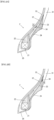
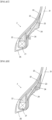
- FIGs. 2A to 2E Specific insertion positions of the electronic component 34 are shown in FIGs. 2A to 2E .
- the electronic component 34 is provided at a position 31% from the bottom of bead core
- the electronic component 34 is provided at a position 40% from the bottom of the bead core
- the electronic component 34 is provided at a position 12% from the bottom of bead core
- the electronic component 34 is provided at a position 29% from the bottom of bead core
- FIG. 2E the electronic component 34 is provided at a position 21% from the bottom of the bead core.
- These values for the positions are values with respect to the distance from the position of the maximum tire width to the bottom of bead core.
- Tables 4 to 7 show the relationship between the formulation and physical properties of the bead reinforcing layer and the clinch, the position of the electronic component, the durability of the tire, and the communication performance of the electronic component.
- the durability of the tire is evaluated as "Y"(acceptable) if it is possible to drive 10,000 km on a general road, and if it is not possible, evaluated as "NG"(not acceptable).
- the mounting rim is 15 ⁇ 6.5 J
- the tire internal pressure is 230 kPa
- the test vehicle is a front wheel drive vehicle
- the displacement is 2000 cc
- the tire mounting position is all wheels.
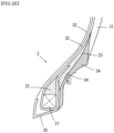
- the evaluation method of communication property is a method where transceivers for the electronic component are installed at three measurement points (a to c) of the circle shown in FIG. 3 and it is judged whether communication of data with the electronic component is possible.
- the tire is assembled in a rim and mounted in a vehicle for conducting the measurement, and the ratio of (the number of readable positions after the durability evaluation / the number of readable positions before the durability evaluation) is calculated.
- the evaluation result is "EX"(excellent), if the average value of the four tire is 60% or more; “G”(good), if 50% or more and less than 60%; “Y”(acceptable), if more than 0% and less than 50%; and "NG”(not acceptable), if 0% or readable position before durability evaluation is 0.
- Examples/ Comparative examples Example 1 Example 2 Compar. example 1 Compar. example 2 Compar. example 3 Compar.
- Example 5 Example 5 Example 6
- Example 7 Formu -lation bead reinforcing layer 3 3 3 4 4 4 clinch member b e f b e f insertion position of electronic component D D D D D D E* bead reinforcing layer 35 35 35 85 85 85 clinch member 10
- 30 50 10
- 30 50 difference 25 5 -15 75 55
- 35 tan ⁇ bead reinforcing layer 0.18 0.18 0.18 0.13 0.13 0.13 clinch member 0.09 0.04 0.18 0.09 0.04 0.18 sum 0.27 0.22 0.36 0.22 0.17 0.31 durability of tire Y Y Y Y Y communication performance of electronic component G Y NG EX EX G
- Example 8 Example 9
- Example 10 Formu-l ation bead reinforcing layer 5 2 6 clinch member e d f insertion position of electronic component D D D E* bead reinforcing layer 100
- 90 clinch member 30 10 50 difference 70
Landscapes
- Engineering & Computer Science (AREA)
- Mechanical Engineering (AREA)
- Tires In General (AREA)
Description
- The present invention relates to a pneumatic tire in which an electronic component such as RFID is embedded.
- In recent years, in order to monitor various data such as the internal pressure, temperature and rotational speed of pneumatic tire (hereinafter, also simply referred to as "tire") to improve safety, maintainability, etc. while the vehicle is traveling, it has been proposed that an electronic component such as transponder for RFID (Radio Frequency Identification) (hereinafter, also simply referred to as "RFID") for recording the data is to be attached to a tire.
- The transponder is a small, lightweight electronic component consisting of a semiconductor chip with a transmitter/receiver circuit, a control circuit, a memory, etc., and an antenna. As the transponder, battery-less one is often used which can transmit various data in the memory as response radio waves when it receives an inquiry radio wave which is used as electrical energy.
- As a method of attaching such an electronic component to a tire, a method has been proposed in which the electronic component is adhered to the surface of the tire after vulcanization by adhesion or the like (for example, Patent Document 1). However, when this method is adopted, there is a problem that the electronic component easily falls-off while traveling on the road surface, although there is little risk that the electronic component is destroyed.
- Then, in order to prevent falling-off of the electronic component, a method has been proposed in which the electronic component is integrated with a tire by vulcanization adhesion accompanying vulcanization molding after embedding the electronic component in the inside of an unvulcanized tire (for example, Patent Document 2).
-
Patent document 3 discloses a related tire.Patent document 4 discloses a tire having the features of the preamble ofclaim 1. -
- [Patent document 1]
JP2006-168473 A - [Patent document 2]
JP2008-265750 A - [Patent document 3]
JP2015-098198 A - [Patent document 4]
JP2016-539047 A - However, when a method is adopted in which an electronic component is embedded in the inside of the unvulcanized tire and then integrated with the tire, there is a problem that the electronic component is easily destroyed by an impact load during traveling on the road surface, and that the durability of the tire is lowered due to the embedded hard electronic component, although there is no risk that the electronic component may fall off. Thus, further improvement is required.
- Therefore, an object of the present invention is to provide a manufacturing technology for tire which is suppressed from being destroyed by an impact load or the like when traveling on a road surface and from deterioration in tire durability, even in the case of a tire having an electronic component embedded therein.
- The inventors of the present invention have earnestly studied for solving the problem, found that the problem can be solved by the invention described below, and completed the present invention.
- The invention is defined by the features of
claim 1. Preferred features are listed in the dependent claims. - According to the present invention, a manufacturing technology for a tire is provided which can manufacture a tire suppressed from being destroyed by an impact load or the like when traveling on a road surface and not causing deterioration in tire durability, even when the tire has an electronic component embedded therein.
-
- [
Figure 1 ] This figure is a cross-sectional view showing a configuration of a pneumatic tire according to an embodiment of the present invention. - [
Figure 2A ] It is a figure explaining the disposed position of the electronic component in an Example of this invention. - [
Figure 2B ] It is a figure explaining the disposed position of the electronic component in an Example of this invention. - [
Figure 2C ] It is a figure explaining the disposed position of the electronic component in an Example of this invention. - [
Figure 2D ] It is a figure explaining the disposed position of the electronic component in an Example of this invention. - [
Figure 2E ] It is a figure explaining the disposed position of the electronic component in an Example of this invention. - [
Figure 3 ] It is a figure explaining the communication measurement points in the Examples of the present invention. - Hereinafter, the present invention will be described based on embodiments.
- As a result of examinations for solving the above-mentioned problems, the present inventors have thought that destruction of the electronic component, which is harder than ordinary rubber, could be suppressed by disposing the electronic component adjacent to the bead apex which is small in deformation during normal traveling. However, in the case where the carcass ply has a structure where the bead apex is wound up by the carcass ply, there is a concern that bringing the electronic component adjacent to the bead apex will be a hindrance to the winding up. Therefore, the bead apex is made smaller, and instead, the bead reinforcing layer is disposed outer side of the end of the carcass ply to bring the electronic component close to the bead reinforcing layer, and the electronic component is provided between the bead reinforcing layer and the clinch portion.
- As a result of further examinations, when disposing the electronic component between the bead reinforcing layer and the clinch portion, if the rubber material of the clinch portion is hard, an external impact is easily transmitted to the electronic component, and there is a possibility of resulting in damage to the electronic component. To prevent the possibility, it was considered necessary to make the rigidity of the clinch portion lower than the rigidity of the bead reinforcing layer. As a result, it was considered that external impact is less likely to be transmitted to the electronic component, and the durability of the embedded electronic component is improved. Thus, the present invention was completed.
- That is, in the tire according to the present invention, the clinch member has a lower rigidity than the bead reinforcing layer, and the electronic component is embedded between the bead reinforcing layer and the clinch member. As a result, destruction of the electronic component due to impact load or the like during traveling on the road surface is suppressed and a tire not causing deterioration in tire durability can be provided.
- A tire according to the present embodiment has a bead reinforcing layer and an electronic component embedded in the tire. The tire according to the present embodiment will be described with reference to
FIG. 1. FIG. 1 is a cross-sectional view showing the configuration of a tire according to an embodiment of the present invention, and more specifically, a cross-sectional view of a tire of size 235 / 75R15. - In
FIG. 1, 1 is a tire, 2 is a bead portion, 3 is a sidewall portion, 4 is a tread, 21 is a bead core, 22 is a bead apex, 23 is a bead reinforcing layer, and 24 is a clinch member (hereinafter also referred to as "clinch"). In this case, the clinch is an external member located inside a sidewall in a tire radial direction, and located outside of a bead reinforcing layer in a tire axial direction. In addition, 25 is a chafer, 31 is a sidewall, 32 is a carcass ply, and 33 is an inner liner. And, 34 denotes an electronic component. InFIG. 1 , H is the distance from the position of the maximum tire width to the bottom of bead core, and L is the distance of theelectronic component 34 from the bottom of bead core. - The
bead reinforcing layer 23 is disposed outer side (right side inFIG. 1 ) of thecarcass ply 32 of thebead portion 2 in the tire axial direction to suppress deformation of the bead apex. The tire axial direction is a direction parallel to the rotation axis of the tire. The tire axial direction outer side means the outer side in the axial direction with the plane passing through the tire equator CL as the center. - Further, a
clinch 24 is disposed adjacent to thebead reinforcing layer 23 in the tire axial direction outer side, and theelectronic component 34 is embedded between thebead reinforcing layer 23 and theclinch 24. Theelectronic component 34 does not have to be directly adjacent to thebead reinforcing layer 23 and theclinch 24, as far as it is provided between thebead reinforcing layer 23 and theclinch 24. For example, theelectronic component 34 may be coated with a rubber material other than thebead reinforcing layer 23 and theclinch 24. - In the tire according to the present embodiment, the
clinch 24 has lower rigidity than thebead reinforcing layer 23. The rigidity of the rubber is usually expressed by E* (complex elastic modulus) or the like, and low rigidity means that theclinch 24 has a lower value of E* than thebead reinforcing layer 23. In the present application, E* means an absolute value. - When E* at 70 °C of
bead reinforcing layer 23 and clinch 24 is expressed as E* (1) MPa and E* (2) MPa, respectively, it is preferable that (E* (1) - E* (2)) satisfies the following formula.
- The right side of above formula is more preferably 20 MPa or more and further preferably 40 MPa or more.
- There is no need to set the upper limit of the above formula in order to exert the effects of the present invention, but in view of easiness of manufacturing a tire, 80 MPa or less is preferable, and 75 MPa or less is more preferable.
- In this case, E* in the above is the value measured under the conditions shown below using a visco-elastic spectrometer (for example, "VESF-3" manufactured by Iwamoto Seisakusho Ltd.) in accordance with the prescription of "JIS K 6394". E* (1) at 70 °C of the rubber composition for bead reinforcing layer is, for example, 10 to 130 MPa, and E* (2) at 70 °C of the rubber composition for clinch is, for example, 7 to 80 MPa.
- Initial strain: 10%
- Amplitude: ± 2.0%
- Frequency: 10 Hz
- Deformation mode: Tension
- Measurement temperature: 70 °C
- And when using the rubber composition for bead reinforcing layers of E* (1) in the range exemplified above, the rubber composition for clinch of E* (2) which satisfies the above formula is used. Similarly, when using the rubber composition for clinch of E* (2) in the range exemplified above, the rubber composition for bead reinforcing layer of E* (1) which satisfies the above formula is used.
- Thus, by making E* (2) of
clinch 24 smaller than E* (1) ofbead reinforcing layer 23, in particular by appropriately controlling the difference as in the above formula, it is possible to reduce the impact on the electronic component and suppress the damage to the electronic component, in addition to maintaining the steering stability of the vehicle and suppressing the deterioration of the durability of the tire. - In the tire of the present embodiment, although peripheral members of the electronic component are hardly deformed and hardly generate heat, heat is still generated. If this heat generation is not suppressed, there is a risk that the temperature of the electronic component may be increased to damage it.
- Therefore, in the present embodiment, when tan δ at 70 °C of the
bead reinforcing layer 23 and theclinch 24 is expressed as tan δ (1) and tan δ (2), respectively, it is preferable that (tan δ (1) + tan δ (2)) satisfies the following formula.
- And the right side of above formula is more preferably 0.32 or less.
- There is no need to set the lower limit of the above formula in order to exert the effects of the present invention, but in view of easiness of manufacturing the tire, 0.1 or more is more preferable, and 0.17 or more is further preferable.
- In the above, tan δ is the value measured in accordance with the same manner as the measurement of E* described above. The tan δ (1) at 70 °C of the rubber composition for bead reinforcing layer is, for example, 0.02 to 0.25, and the tan δ (2) at 70 °C of the rubber composition for clinch is, for example, 0.02 to 0.29.
- And when using the rubber composition for bead reinforcing layer of tan δ (1) in the range exemplified above, the rubber composition for clinch of tan δ (2) which satisfies the above-mentioned formula is used. Similarly, in the case of using the rubber composition for clinch of tan δ (2) in the range exemplified above, the rubber composition for bead reinforcing layer of tan δ (1) which satisfies the above formula is used.
- Thus, by appropriately controlling the tan δ of the
bead reinforcing layer 23 and theclinch 24, it is possible to suppress the increase in temperature around the electronic component, when both of thebead reinforcing layer 23 and theclinch 24 have low heat generation properties. In addition, even when one of them has low heat generation property, since the heat can be dissipated from the high side to the low side, it is possible to suppress the increase in temperature around the electronic component. - An electronic component is embedded in a tire according to the present embodiment. Specific examples of the electronic components include RFID, pressure sensor, temperature sensor, acceleration sensor, magnetic sensor, groove depth sensor, and the like. Above all, RFID is particularly preferred, since it can store and read a large capacity of information without contact, that is, it can store tire manufacturing information, management information, customer information, and the like in addition to data such as pressure and temperature.
- In the present embodiment, the
electronic component 34 is embedded between thebead reinforcing layer 23 and theclinch 24. As a result, compared to the case where the electronic component is disposed on the carcass side of the inner layer of tire, it is possible to suppress the occurrence of local stress concentration which becomes the fracture start point of the carcass. The specific embedding position is not particularly limited as far as reliable information communication is possible and the electronic component is not easily damaged by the deformation of the tire. As a position where the damage of the electronic component by the deformation of the tire is relatively small and communication from the outside can be made without problems when assembled in the rim, a position outer side of the end of carcass in tire axial direction where the height from the bottom of bead core (L inFIG. 1 ) is 20 to 80% with respect to the distance from the position of the maximum tire width to the bottom of bead core in the equatorial direction (H inFIG. 1 ) in the tire cross-sectional view is preferable. - The longitudinal size (overall length including the IC chip and the antenna) of the electronic component to be embedded in the present embodiment is preferably 18 cm or less, more preferably 9 cm or less, further more preferably 4 cm or less, and most preferably 2 cm or less. With such a small size, although stress may be concentrated on the surrounding rubber, the durability of the tire can be stably maintained, since consideration is given to local stress concentration in the present embodiment, as described above. At this time, bending of the antenna portion can be kept to a minimum by arranging the antenna portion of the electronic component to extend in an orthogonal direction to the cord of carcass.
- In the present embodiment, the rubber composition used for producing the bead reinforcing layer can be obtained by kneading a rubber component and a curable resin, as main components, and various compounding materials, such as a reinforcing material, an anti-aging agent and an additive.
- As the rubber component, for example, diene rubbers such as natural rubber (NR), isoprene rubber (IR), butadiene rubber (BR), styrene butadiene rubber (SBR), acrylonitrile butadiene rubber (NBR), chloroprene rubber (CR), butyl rubber (IIR), and the like can be mentioned. Among them, isoprene-based rubbers (NR and IR) are preferable from the viewpoint that steering stability, low fuel consumption and extrusion processability can be favorably improved.
- Content of the isoprene-based rubber (NR or IR) is preferably 50 parts by mass or more, and more preferably 60 parts by mass or more in 100 parts by mass of the rubber component. By setting the content of isoprene-based rubber (NR and IR) as described above, sufficient breaking strength and sufficient hardness can be secured.
- It is preferable that a curable resin is compounded in the rubber composition of the bead reinforcing layer for enhancing the rigidity. As the curable resin, a phenol-type resin can be mentioned although it is not specifically limited.
- Specific examples of the phenol-type resins include phenolic resins and modified phenolic resins. Here, the phenolic resin is obtained by reacting phenol with an aldehyde such as formaldehyde, acetaldehyde, furfural or the like by an acid or an alkali catalyst. The modified phenolic resin is a phenolic resin modified with a compound such as cashew oil, tall oil, linseed oil, various animal and vegetable oils, unsaturated fatty acids, rosins, alkylbenzene resins, aniline and melamine.
- As the phenol resin, a modified phenol resin is preferable, and a cashew oil modified phenol resin and a rosin modified phenol resin are more preferable from the viewpoint that a good hardness can be obtained by a curing reaction.
- Content of the curable resin in the rubber composition is preferably 5 parts by mass or more, and more preferably 10 parts by mass or more with respect to 100 parts by mass of the rubber component. Moreover, it is preferably 25 parts by mass or less, and more preferably 20 parts by mass or less. By setting the content of the curable resin within the above range, sufficient rigidity and steering stability can be secured.
- In the case of compounding a phenolic resin as a curable resin, it is preferable to further contain a curing agent having a curing action with the phenolic resin. The specific curing agent is not particularly limited as far as it has the above-mentioned curing action, and, for example, hexamethylenetetramine (HMT), hexamethoxymethylolmelamine (HMMM), hexamethoxymethylol pantamethylether (HMMPME), melamine, methylolmelamine and the like can be mentioned. Among them, HMT, HMMM, and HMMPME are preferable from the viewpoint of being excellent in the action of increasing the hardness of the phenolic resin.
- Content of the curing agent is preferably 1 part by mass or more, and more preferably 5 parts by mass or more with respect to 100 parts by mass of the phenolic resin. If the amount is less than 1 part by mass, sufficient curing may not be possible. Moreover, it is preferably 20 parts by mass or less, and more preferably 15 parts by mass or less. If it exceeds 20 parts by mass, the curing may be uneven, and scorch may occur during extrusion.
- It is preferable that carbon black is compounded as a reinforcing material in the rubber composition of the present embodiment. Examples of carbon black include GPF, HAF, ISAF, SAF, FF, FEF and the like. One of these carbon blacks may be used alone, or two or more thereof may be used in combination. Among these, hard carbon-based ISAF, SAF and HAF are preferable from the viewpoint of securing the hardness. Among them, HAF is particularly preferable.
- Content of carbon black in the above rubber composition is preferably 30 parts by mass or more, and more preferably 45 parts by mass or more with respect to 100 parts by mass of the rubber component. Moreover, it is preferably 70 parts by mass or less, and more preferably 65 parts by mass or less. By setting the content of carbon black in the rubber composition within the above range, sufficient fracture characteristics can be obtained.
- Sulfur is used as a vulcanizing agent, and its content is preferably 1 part by mass or more, and more preferably 2 parts by mass or more with respect to 100 parts by mass of the rubber component. Moreover, it is preferably 8 parts by mass or less, and more preferably 6 parts by mass or less. By setting the content of sulfur within the above range, sufficient steering stability can be secured, the bloom and adhesion of sulfur can be suppressed, and the durability can be secured. Content of sulfur is pure sulfur content, and when using insoluble sulfur, it is content except oil content.
- Sulfur is usually used together with a vulcanization accelerator. Content of the vulcanization accelerator is preferably 1.5 parts by mass or more, and more preferably 2.0 parts by mass or more with respect to 100 parts by mass of the rubber component. Moreover, it is preferably 5.0 parts by mass or less, and more preferably 4.0 parts by mass or less. By setting the content of the vulcanization accelerator within the above range, the effects of the present invention tend to be favorably obtained. As specific examples of the vulcanization accelerators, sulfenamide type, thiazole type, thiuram type, thiourea type, guanidine type, dithiocarbamic acid type, aldehyde-amine type or aldehyde-ammonia type, imidazoline type, and xanthate type vulcanization accelerators can be mentioned. These vulcanization accelerators may be used alone or in combination of two or more. Among these, sulfenamide type vulcanization accelerators are preferred because the scorch time and the vulcanization time can be balanced.
- As stearic acid, conventionally known products can be used. For example, products manufactured by NOF Corporation, Kao Corporation, Wako Pure Chemical Industries, Ltd., Chiba Fatty Acid Corporation, etc. can be used. When stearic acid is used, content of stearic acid is preferably 0.5 part by mass or more, and more preferably 1 part by mass or more with respect to 100 parts by mass of the rubber component. Moreover, it is preferably 10 parts by mass or less, and more preferably 5 parts by mass or less. By setting the content of stearic acid within the above range, the effects of the present invention tend to be obtained favorably.
- As zinc oxide, conventionally known ones can be used. For example, products manufactured by Mitsui Mining & Smelting Co., Ltd., Toho Zinc Co., Ltd., Hakusui Tech Co., Ltd., Shodo Chemical Industry Co., Ltd., Sakai Chemical Industry Co., Ltd., etc. can be used. When using zinc oxide, content of zinc oxide is preferably 0.5 part by mass or more, and more preferably 1 part by mass or more with respect to 100 parts by mass of the rubber component. Moreover, it is preferably 10 parts by mass or less, and more preferably 5 parts by mass or less. By setting the content of zinc oxide within the above range, the effects of the present invention tend to be obtained favorably.
- As the anti-aging agent, an amine-type anti-aging agent having an excellent ozone resistance effect is preferable. The amine-type anti-aging agent is not particularly limited, and examples thereof include amine derivatives such as diphenylamine-type, p-phenylenediamine-type, naphthylamine-type and ketone amine condensate-type ones. These may be used alone, and two or more may be used in combination. Examples of diphenylamine type derivatives include p-(p-toluenesulfonylamide) -diphenylamine, octylated diphenylamine, 4,4'-bis (α, α'-dimethylbenzyl) diphenylamine and the like. Examples of p-phenylenediamine type derivatives include N- (1,3-dimethylbutyl) -N'-phenyl-p-phenylenediamine (6PPD), N-phenyl-N'-isopropyl-p-phenylenediamine (IPPD) and N, N'-di-2-naphthyl-p-phenylenediamine. Examples of the naphthylamine type derivatives include phenyl-α-naphthylamine and the like. Among them, phenylenediamine type and ketone amine condensate type are preferable. Content of the anti-aging agent is preferably 0.3 part by mass or more, and more preferably 0.5 part by mass or more with respect to 100 parts by mass of the rubber component. Moreover, it is preferably 8 parts by mass or less, and more preferably 2.5 parts by mass or less.
- Waxes are not particularly limited, and petroleum waxes such as paraffin wax and microcrystalline wax; natural waxes such as plant wax and animal waxes; synthetic waxes such as polymers of ethylene and propylene etc. can be mentioned as the examples. These may be used alone or in combination of two or more. As specific examples of wax, products manufactured by Ouchi Shinko Chemical Co., Ltd., Nippon Seiro Co., Ltd., Seiko Kagaku Co., Ltd., etc. can be used. When a wax is used, content of the wax is preferably 0.5 part by mass or more, and more preferably 1 part by mass or more with respect to 100 parts by mass of the rubber component. Moreover, it is preferably 10 parts by mass or less, and more preferably 7 parts by mass or less.
- Examples of oils include process oils, vegetable oils and fats, and mixtures thereof. As the process oil, for example, paraffin-based process oil, aroma-based process oil, naphthene-based process oil and the like can be used. Examples of vegetable fats and oils include castor oil, cottonseed oil, linseed oil, rapeseed oil, soybean oil, palm oil, coconut oil, peanut oil, rosin, pine oil, pine tar, tall oil, corn oil, rice oil, beni flower oil, sesame oil, olive oil, sunflower oil, palm kernel oil, camellia oil, jojoba oil, macadamia nut oil and tung oil. These may be used alone or in combination of two or more. Specific examples of the oil which can be used include products manufactured by Idemitsu Kosan Co., Ltd., Sankyo Yuka Kogyo Co., Ltd., Japan Energy Co., Ltd., Orisoi Company, H & R Company, Toyokuni Oil Co., Ltd., Showa Shell Co., Ltd., Fuji Kosan Co., Ltd., etc. Content of oil is preferably 0.5 part by mass or more, and more preferably 1 part by mass or more with respect to 100 parts by mass of the rubber component. Moreover, it is preferably 10 parts by mass or less, and more preferably 5 parts by mass or less.
- In addition to the above components, the rubber composition of the present embodiment may also contain compounding materials conventionally used in the rubber industry. For example, inorganic fillers such as silica, talc and calcium carbonate, and organic fillers such as cellulose fibers, softeners such as liquid rubber and adhesive resins, vulcanizing agents other than sulfur, organic crosslinking agents, and the like may be compounded as needed. About the compounding quantity of each compounding material, it can be selected suitably.
- As described above, the bead reinforcing layer is preferably adjusted so that E* and tan δ satisfy the predetermined formulas with respect to the clinch. As an adjustment method of E* of a bead reinforcing layer, adjustment by increase or decrease of curable resin can be mentioned. As shown in Examples described later, E* can be increased by increasing the amount of the curable resin. Also, E* can be adjusted by increase or decrease of the carbon black and the sulfur content. As shown in Examples described later, E* can be increased by increasing carbon black and sulfur. However, when the amount of carbon black is increased, tan δ is increased, and when the amount of sulfur is increased, tan δ is decreased. Therefore, it is preferable to adopt a method where use of the curable resin and use amount of it is determined first, then the amount of sulfur is adjusted and thereafter the amount of carbon black is adjusted finally. This method allows the aimed E* and tan δ can be achieved without the need for excessive trial and error.
- The rubber composition of the
clinch 24 is basically the same as the rubber composition used for thebead reinforcing layer 23, but the rubber composition of theclinch 24 is adjusted to have the rigidity lower than that of the rubber composition of the bead reinforcing layer. In the present embodiment, it is possible to adjust the compounding amount of the materials while using the same materials other than the rubber component. Therefore, a rubber component in the above embodiment will be described below. - Basically, the same rubber component as that of the bead reinforcing layer can be used. For example, combined use of isoprene-based rubber (NR or IR) and BR is more preferred, because good fuel consumption and durability can be obtained.
- Content of the isoprene-based rubber (NR or IR) is preferably 10 parts by mass or more, and more preferably 30 parts by mass or more in 100 parts by mass of the rubber component. Moreover, it is preferably 80 parts by mass or less, and more preferably 50 parts by mass or less. By setting the content of isoprene-based rubber (NR or IR) in the rubber component within the above range, sufficient breaking elongation and sufficient bending crack growth resistance can be secured.
- Content of the BR is preferably 20 parts by mass or more, and more preferably 50 parts by mass or more in 100 parts by mass of the rubber component. Moreover, it is preferably 90 parts by mass or less, and more preferably 70 parts by mass or less. By setting the content of BR in the rubber component within the above range, sufficient bending crack growth resistance and sufficient breaking strength can be secured.
- The BR is not particularly limited. For example, BR having a high cis content, BR containing syndiotactic polybutadiene crystals (SPB-containing BR), modified BR, and the like can be used. Among them, SPB-containing BR is preferable from the viewpoint that extrusion processability can be greatly improved by the intrinsic orientation crystal component.
- In the combined use of isoprene-based rubber (NR or IR) and BR, total content of isoprene rubber (NR or IR) and BR is preferably 80 parts by mass or more, and more preferably 90 parts by mass or more in 100 parts by mass of the rubber component. By setting the total content of isoprene-based rubber (NR and IR) and BR within the above range, sufficient low fuel consumption and sufficient durability can be secured.
- As described above, the clinch is configured to be low in rigidity with respect to the bead reinforcing layer, and preferably adjusted so that E* and tan δ satisfy the predetermined relational formulas. The adjustment method of clinch E* may be the same adjustment method as that in the bead reinforcing layer, but it is preferable to adjust it by the amount of carbon black or sulfur without using the curable resin as much as possible. That is, it is preferable to adjust the amount of sulfur first, then adjust the amount of carbon black, and finally adjust the amount of curable resin. This allows the aimed E* and tan δ can be achieved without the need for excessive trial and error.
- The rubber compositions of the bead reinforcing layer and the clinch can be manufactured by a known method, for example, by a method of kneading the above-mentioned components using a rubber kneading apparatus such as an open roll or a banbury mixer.
- The tire according to the present embodiment can be manufactured by a usual method except for embedding an electronic component in the middle of molding. That is, the
bead reinforcing layer 23 and theclinch 24 are molded by extrusion processing according to the shape of the bead apex at the unvulcanized stage of the rubber composition, and pasted together with the other tire members on a tire forming machine according to the usual method and an unvulcanized tire is formed. In the middle of molding, the electronic component is embedded at a predetermined position between the bead reinforcing layer and the clinch. - Thereafter, a tire is manufactured by heating and pressing the molded unvulcanized tire in which an electronic component is embedded in a vulcanizer.
- Table 1 shows the compounding materials. Table 2 and Table 3 show the formulation.
[Table 1] Compounding materials Product Name Manufacturer (Rubber component) NR TSR20 BR UBEPOL BR 150B Ube Industries, Ltd. (Reinforcing material) Carbon Black N330 Showa Cabot Co., Ltd. (Curable resin·Curing agent) Curable resin PR 12686 Sumitomo Bakelite Co., Ltd. Curing agent 1SUMIKANOL 507AP Taoka Chemical Co., Ltd. Curing agent 2SANCELER HMT Sanshin Chemical Industry Co., Ltd. (Softener) Oil Diana Process AH-24 Idemitsu Kosan Co., Ltd (Anti-aging agent) Anti-aging agent 1NOCLAC 6C Ouchi Shinko Chemical Co., Ltd. Anti-aging agent 2NOCLAC RD Ouchi Shinko Chemical Co., Ltd. (Vulcanizing agent) Sulfur Insoluble Sulfur Tsurumi Chemical Industry Co., Ltd. Vulcanization accelerator SANCELERNS-G Sanshin Chemical Industry Co., Ltd. (Others) Stearic acid Camellia oil NOF CORPORATION Zinc oxide Zinc Flower 1 Mitsui Mining & Smelting Co., Ltd. Wax SANNOC N Ouchi Shinko Chemical Co., Ltd. [Table 2] Formulation 1 2 3 4 5 6 NR 100 100 100 100 100 100 Carbon Black 60 80 60 50 50 80 Curable resin 13 20 7 22 20 15 Zinc oxide 4 4 4 4 4 4 Stearic acid 2 2 2 2 2 2 Oil 2 2 2 2 2 2 Anti-aging agent 1 1 1 1 1 1 1 Sulfur 3 3 3 3 4.5 3 Vulcanization accelerator 2.5 2.5 2.5 2.5 3 2.5 Curing agent 1 0.5 0.5 0.5 0.5 0.5 0.5 Curing agent 2 1.3 2 0.7 2.2 2.2 2 E* 50 90 35 85 100 80 tan δ 0.18 0.2 0.18 0.13 0.06 0.22 [Table 3] Formulation a b c d e f NR 40 40 40 40 40 40 BR 60 60 60 60 60 60 Carbon Black 65 45 50 55 50 70 Curable resin - - 15 - - 7 Zinc oxide 3 3 3 3 3 3 Stearic acid 2 2 2 2 2 2 Oil 2 2 2 2 2 2 Wax 1.5 1.5 1.5 1.5 1.5 1.5 Anti-aging agent 1 1.5 1.5 1.5 1.5 1.5 1.5 Anti-aging agent 2 1 1 1 1 1 1 Sulfur 2.5 2.5 2.5 3 6 2.5 Vulcanization accelerator 3.2 3.2 3.2 3.2 3.2 3.2 Curing agent 1 - - 0.5 - - - Curing agent 2 - - 1.5 - - 0.7 E* 15 10 70 10 30 50 tan δ 0.15 0.09 0.12 0.12 0.04 0.18 - Based on the formulations in Table 1 and Table 2, using a banbury mixer manufactured by Kobe Steel, Ltd., compounding materials other than sulfur and a vulcanization accelerator are kneaded, then sulfur and a vulcanization accelerator are added to the kneaded product thus obtained, followed by kneading using an open roll, and an unvulcanized rubber composition for a bead reinforcing layer can be obtained.
- Moreover, based on the formulations in Table 1 and Table 3, an unvulcanized rubber composition for clinch can be obtained. Moreover, according to Example 1 in
JP2013-245339A electronic component 34 can be obtained. - Then, the obtained unvulcanized rubber composition is molded into the shape of a bead reinforcing layer or a clinch, respectively, and the unvulcanized rubber composition is laminated and pasted together with other tire members on a tire molding machine. A test tire (tire size: 195/65R15) can be obtained by placing the
electronic component 34 coated with an unvulcanized rubber composition on a position shown in any ofFIGs. 2A to 2E described later and carrying out the vulcanization at 150 °C for 30 minutes. As theelectronic component 34, an RFID in which a 30 mm antenna is provided on both sides of a 3 mm × 3 mm × 0.4 mm IC chip can be used. - The physical properties (E* and tan δ) in each of the formulations shown in Table 2 and Table 3 above are measured by the following methods.
- That is, a rubber sample is extracted from each of the bead reinforcing layer and the clinch member of each pneumatic tire, and E* and tan δ are measured using a viscoelastic spectrometer ("VESF-3" manufactured by Iwamoto Manufacturing Co., Ltd.) under the following conditions.
Initial strain: 10% Amplitude: ± 2.0% Frequency: 10 Hz Deformation mode: Tension Measurement temperature: 70 °C - Specific insertion positions of the
electronic component 34 are shown inFIGs. 2A to 2E . InFIG. 2A , theelectronic component 34 is provided at aposition 31% from the bottom of bead core, inFIG. 2B , theelectronic component 34 is provided at a position 40% from the bottom of the bead core, and inFIG. 2C , theelectronic component 34 is provided at a position 12% from the bottom of bead core, inFIG. 2D , theelectronic component 34 is provided at a position 29% from the bottom of bead core, and inFIG. 2E , theelectronic component 34 is provided at aposition 21% from the bottom of the bead core. These values for the positions are values with respect to the distance from the position of the maximum tire width to the bottom of bead core. - Tables 4 to 7 show the relationship between the formulation and physical properties of the bead reinforcing layer and the clinch, the position of the electronic component, the durability of the tire, and the communication performance of the electronic component.
- The durability of the tire is evaluated as "Y"(acceptable) if it is possible to drive 10,000 km on a general road, and if it is not possible, evaluated as "NG"(not acceptable). Regarding the driving conditions, the mounting rim is 15 × 6.5 J, the tire internal pressure is 230 kPa, the test vehicle is a front wheel drive vehicle, the displacement is 2000 cc, and the tire mounting position is all wheels.
- The evaluation method of communication property is a method where transceivers for the electronic component are installed at three measurement points (a to c) of the circle shown in
FIG. 3 and it is judged whether communication of data with the electronic component is possible. - Specifically, the tire is assembled in a rim and mounted in a vehicle for conducting the measurement, and the ratio of (the number of readable positions after the durability evaluation / the number of readable positions before the durability evaluation) is calculated. The evaluation result is "EX"(excellent), if the average value of the four tire is 60% or more; "G"(good), if 50% or more and less than 60%; "Y"(acceptable), if more than 0% and less than 50%; and "NG"(not acceptable), if 0% or readable position before durability evaluation is 0.
[Table 4] Examples/ Comparative examples Example 1 Example 2 Compar. example 1 Compar. example 2 Compar. example 3 Compar. example 4 Formu -lation bead reinforcing layer 1 1 1 1 1 1 clinch member b e f c b e insertion position of electronic component D D D D A A E* bead reinforcing layer 50 50 50 50 50 50 clinch member 10 30 50 70 10 30 difference 40 20 0 -20 40 20 tan δ bead reinforcing layer 0.18 0.18 0.18 0.18 0.18 0.18 clinch member 0.09 0.04 0.18 0.12 0.09 0.04 sum 0.27 0.22 0.36 0.30 0.27 0.22 durability of tire Y Y Y Y Y Y communication performance of electronic component EX G NG NG NG NG [Table 5] Examples/ Comparative examples Example 3 Example 4 Compar. Example 5 Example 5 Example 6 Example 7 Formu -lation bead reinforcing layer 3 3 3 4 4 4 clinch member b e f b e f insertion position of electronic component D D D D D D E* bead reinforcing layer 35 35 35 85 85 85 clinch member 10 30 50 10 30 50 difference 25 5 -15 75 55 35 tan δ bead reinforcing layer 0.18 0.18 0.18 0.13 0.13 0.13 clinch member 0.09 0.04 0.18 0.09 0.04 0.18 sum 0.27 0.22 0.36 0.22 0.17 0.31 durability of tire Y Y Y Y Y Y communication performance of electronic component G Y NG EX EX G [Table 6] Examples/ Comparative examples Example 8 Example 9 Example 10 Formu-l ation bead reinforcing layer 5 2 6 clinch member e d f insertion position of electronic component D D D E* bead reinforcing layer 100 90 80 clinch member 30 10 50 difference 70 80 30 tan δ bead reinforcing layer 0.06 0.2 0.22 clinch member 0.04 0.12 0.18 sum 0.1 0.32 0.4 durability of tire Y Y Y communication performance of electronic component EX EX G [Table 7] Examples/ Comparative examples Comparative Example 6 Example 11 Example 12 Example 13 Formu-l ation bead reinforcing layer 4 4 4 4 clinch member b b b b insertion position of electronic component A B C E E* bead reinforcing layer 85 85 85 85 clinch member 10 10 10 10 difference 75 75 75 75 tan δ bead reinforcing layer 0.13 0.13 0.13 0.13 clinch member 0.09 0.09 0.09 0.09 sum 0.22 0.22 0.22 0.22 durability of tire NG Y Y Y communication performance of electronic component - G Y G - As mentioned above, although the present invention was explained based on embodiments, the present invention is not limited to the above-mentioned embodiments. Various modifications can be made to the above embodiments within the scope of the present invention.
-
- 1
- tire
- 2
- bead portion
- 3
- side wall portion
- 4
- tread
- 21
- bead core
- 22
- bead apex
- 23
- bead reinforcing layer
- 24
- clinch
- 25
- chaffer
- 31
- side wall
- 32
- carcass ply
- 33
- inner liner
- 34
- electronic component
- CL
- tire equator
- H
- Distance from the position of the maximum tire width to the bottom of bead core
- L
- Distance from bottom of bead core of electronic component
Claims (12)
- A pneumatic tire (1) which hasa bead reinforcing layer (23) which is provided to the outer side of the carcass of the bead portion (2) in the tire axial direction and reinforces the bead portion (2) from the outer side of the carcass; andan electronic component (34);characterized bya clinch member (24) provided to the outer side of the bead reinforcing layer (23) in the tire axial direction,wherein the clinch member (24) has a lower value of complex elastic modulus E* than the bead reinforcing layer (23), and the electronic component (34) is embedded between the bead reinforcing layer (23) and the clinch member (24), the value of complex elastic modulus E* being measured using a viscoelastic spectrometer in accordance with the prescription of "JIS K 6394" under an initial strain of 10%, at an amplitude of ± 2.0%, a frequency of 10 Hz and a measurement temperature of 70 °C, under tensile deformation mode.
- The pneumatic tire according to claim 1 whereinthe bead reinforcing layer (23) and the clinch member (24) are each made of a rubber composition; andE* (1) of the bead reinforcing layer (23) and E* (2) of the clinch member (24), at 70 °C, satisfy the following formula.

- The pneumatic tire according to claim 2 wherein
E* (1) of the bead reinforcing layer (23) and E* (2) of the clinch member (24), at 70 °C, satisfy the following formula.
- The pneumatic tire according to claim 3 wherein
E* (1) of the bead reinforcing layer (23) and E* (2) of the clinch member (24), at 70 °C, satisfy the following formula.
- The pneumatic tire according to any one of claims 1-4 wherein E* (1) of the bead reinforcing layer (23) and E* (2) of the clinch member (24), at 70 °C, satisfy the following formula.

- The pneumatic tire according to claim 5 wherein
E* (1) of the bead reinforcing layer (23) and E* (2) of the clinch member (24),
at 70 °C, satisfy the following formula.
- The pneumatic tire according to any one of claims 1-6 wherein the bead reinforcing layer (23) and the clinch member (24) are each made of a rubber composition; and
tan δ (1) of the bead reinforcing layer (23) and tan δ (2) of the clinch member (24), at 70 °C, satisfy the following formula.
- The pneumatic tire according to claim 7 wherein
tan δ (1) of the bead reinforcing layer (23) and tan δ (2) of the clinch member (24), at 70 °C, satisfy the following formula.
- The pneumatic tire according to any one of claims 1-8 wherein
tan δ (1) of the bead reinforcing layer (23) and tan δ (2) of the clinch member (24), at 70 °C, satisfy the following formula.
- The pneumatic tire according to claim 9 wherein
tan δ (1) of the bead reinforcing layer (23) and tan δ (2) of the clinch member (24), at 70 °C, satisfy the following formula.
- The pneumatic tire according to any one of claims 1-10 wherein the electronic component (34) is located on the outer side of the carcass in the tire axial direction in the cross-sectional view, and is embedded at a position of 20 to 80% from the bottom of bead core (21) with respect to the distance (H) from the position of the maximum tire width to the bottom of bead core (21) in the equatorial direction.
- The pneumatic tire according to any one of claims 1-11 wherein the electronic component (34) is a transponder for RFID.
Applications Claiming Priority (2)
| Application Number | Priority Date | Filing Date | Title |
|---|---|---|---|
| JP2017175248 | 2017-09-12 | ||
| PCT/JP2018/032660 WO2019054226A1 (en) | 2017-09-12 | 2018-09-03 | Pneumatic tire |
Publications (3)
| Publication Number | Publication Date |
|---|---|
| EP3677452A1 EP3677452A1 (en) | 2020-07-08 |
| EP3677452A4 EP3677452A4 (en) | 2021-08-18 |
| EP3677452B1 true EP3677452B1 (en) | 2023-04-19 |
Family
ID=65722772
Family Applications (1)
| Application Number | Title | Priority Date | Filing Date |
|---|---|---|---|
| EP18857265.5A Active EP3677452B1 (en) | 2017-09-12 | 2018-09-03 | Pneumatic tire |
Country Status (5)
| Country | Link |
|---|---|
| US (1) | US12054011B2 (en) |
| EP (1) | EP3677452B1 (en) |
| JP (1) | JP6529701B1 (en) |
| CN (1) | CN111051086B (en) |
| WO (1) | WO2019054226A1 (en) |
Families Citing this family (42)
| Publication number | Priority date | Publication date | Assignee | Title |
|---|---|---|---|---|
| FR3059592A1 (en) | 2016-12-05 | 2018-06-08 | Compagnie Generale Des Etablissements Michelin | METHOD FOR MANUFACTURING A PATCH EQUIPPED WITH A RADIOFREQUENCY AND PNEUMATIC TRANSPONDER COMPRISING SUCH A PATCH |
| FR3059604A1 (en) | 2016-12-05 | 2018-06-08 | Compagnie Generale Des Etablissements Michelin | PNEUMATIC ENVELOPE EQUIPPED WITH AN ELECTRONIC MEMBER |
| FR3059603A1 (en) * | 2016-12-07 | 2018-06-08 | Compagnie Generale Des Etablissements Michelin | PNEUMATIC ADAPTED FOR FLAT ROLLING EQUIPPED WITH AN ELECTRONIC MEMBER |
| CN111741858B (en) * | 2018-03-07 | 2022-09-16 | 米其林集团总公司 | Tire provided with radio frequency communication module |
| KR20190115627A (en) * | 2018-04-03 | 2019-10-14 | 한국타이어앤테크놀로지 주식회사 | Tire comprising radio freqeuncy indentification system |
| JP6594509B1 (en) | 2018-10-03 | 2019-10-23 | Toyo Tire株式会社 | Tire and tire manufacturing method |
| JP6698194B1 (en) * | 2019-04-24 | 2020-05-27 | Toyo Tire株式会社 | Tire and method for manufacturing tire |
| JP7227847B2 (en) * | 2019-05-17 | 2023-02-22 | Toyo Tire株式会社 | tire |
| JP7401205B2 (en) * | 2019-06-19 | 2023-12-19 | Toyo Tire株式会社 | tire |
| JP7345290B2 (en) * | 2019-06-19 | 2023-09-15 | Toyo Tire株式会社 | tire |
| DE102019209779A1 (en) * | 2019-07-03 | 2021-01-07 | Continental Reifen Deutschland Gmbh | tires |
| JP7222856B2 (en) * | 2019-09-13 | 2023-02-15 | Toyo Tire株式会社 | Tire and tire manufacturing method |
| US12138969B2 (en) | 2020-02-17 | 2024-11-12 | The Yokohama Rubber Co., Ltd. | Pneumatic tire |
| JP7469606B2 (en) * | 2020-02-17 | 2024-04-17 | 横浜ゴム株式会社 | Pneumatic tires |
| JP7343786B2 (en) * | 2020-02-17 | 2023-09-13 | 横浜ゴム株式会社 | pneumatic tires |
| JP7842522B2 (en) * | 2020-02-17 | 2026-04-08 | 横浜ゴム株式会社 | pneumatic tires |
| WO2021166795A1 (en) * | 2020-02-17 | 2021-08-26 | 横浜ゴム株式会社 | Rfid module, and pneumatic tire with same embedded therein |
| JP7842524B2 (en) * | 2020-02-17 | 2026-04-08 | 横浜ゴム株式会社 | pneumatic tires |
| JP7343784B2 (en) * | 2020-02-17 | 2023-09-13 | 横浜ゴム株式会社 | pneumatic tires |
| JP7842523B2 (en) * | 2020-02-17 | 2026-04-08 | 横浜ゴム株式会社 | pneumatic tires |
| JP7469605B2 (en) * | 2020-02-17 | 2024-04-17 | 横浜ゴム株式会社 | Pneumatic tires |
| DE112021000321B4 (en) * | 2020-02-17 | 2023-11-09 | The Yokohama Rubber Co., Ltd. | tire |
| WO2021166793A1 (en) * | 2020-02-17 | 2021-08-26 | 横浜ゴム株式会社 | Pneumatic tire |
| JP7343785B2 (en) * | 2020-02-17 | 2023-09-13 | 横浜ゴム株式会社 | pneumatic tires |
| JP7448814B2 (en) * | 2020-05-28 | 2024-03-13 | 横浜ゴム株式会社 | pneumatic tires |
| JP7457250B2 (en) * | 2020-06-29 | 2024-03-28 | 横浜ゴム株式会社 | pneumatic tires |
| JP7425310B2 (en) * | 2020-06-29 | 2024-01-31 | 横浜ゴム株式会社 | pneumatic tires |
| JP7410404B2 (en) * | 2020-06-29 | 2024-01-10 | 横浜ゴム株式会社 | pneumatic tires |
| JP7505301B2 (en) * | 2020-07-06 | 2024-06-25 | 住友ゴム工業株式会社 | Pneumatic tires |
| JP6819026B1 (en) | 2020-08-04 | 2021-01-27 | 住友ゴム工業株式会社 | Pneumatic tires |
| JP6945807B1 (en) * | 2020-09-01 | 2021-10-06 | 住友ゴム工業株式会社 | Pneumatic tires |
| TWI759876B (en) * | 2020-09-23 | 2022-04-01 | 正新橡膠工業股份有限公司 | Tire having electrical part |
| JP7599903B2 (en) * | 2020-10-27 | 2024-12-16 | Toyo Tire株式会社 | tire |
| JP7603422B2 (en) * | 2020-11-20 | 2024-12-20 | Toyo Tire株式会社 | tire |
| JP7671136B2 (en) * | 2020-11-20 | 2025-05-01 | Toyo Tire株式会社 | tire |
| JP7519961B2 (en) * | 2021-06-30 | 2024-07-22 | 株式会社ブリヂストン | tire |
| JP7712194B2 (en) * | 2021-12-08 | 2025-07-23 | 株式会社ブリヂストン | tire |
| JP7712195B2 (en) * | 2021-12-08 | 2025-07-23 | 株式会社ブリヂストン | tire |
| JP7262563B1 (en) * | 2021-12-24 | 2023-04-21 | 横浜ゴム株式会社 | Solid tire and its manufacturing method |
| JP7262564B1 (en) | 2021-12-24 | 2023-04-21 | 横浜ゴム株式会社 | Solid tire and its manufacturing method |
| JP7447938B2 (en) | 2022-06-24 | 2024-03-12 | 住友ゴム工業株式会社 | Heavy load tires |
| FI131252B1 (en) * | 2023-12-22 | 2025-01-08 | Teknologian Tutkimuskeskus Vtt Oy | An arrangement to measure a tyre pressure |
Family Cites Families (17)
| Publication number | Priority date | Publication date | Assignee | Title |
|---|---|---|---|---|
| JPH0832816B2 (en) * | 1989-06-08 | 1996-03-29 | 住友デュレズ株式会社 | Method for producing phenolic resin composition and rubber composition applying the same |
| US20010042583A1 (en) * | 1997-10-02 | 2001-11-22 | Filomeno Gennaro Corvasce | Tire with chafer composition |
| JP3860921B2 (en) * | 1998-10-01 | 2006-12-20 | 横浜ゴム株式会社 | Auxiliary parts for tire transponders |
| EP1412207B1 (en) * | 2001-07-19 | 2008-04-16 | Société de Technologie Michelin | Runflat insert for tires |
| WO2003105509A1 (en) * | 2002-06-11 | 2003-12-18 | Societe De Technologie Michelin | A radio frequency antenna embedded in a tire |
| JP4555673B2 (en) | 2004-12-14 | 2010-10-06 | 住友ゴム工業株式会社 | PNEUMATIC TIRE WITH ELECTRONIC COMPONENT STORAGE AND METHOD |
| JP2007049351A (en) | 2005-08-09 | 2007-02-22 | Yokohama Rubber Co Ltd:The | Electronic tag for tire and pneumatic tire |
| FR2914585B1 (en) | 2007-04-03 | 2009-07-03 | Michelin Soc Tech | PNEUMATIC COMPRISING AN ELECTRONIC MEMBER AND METHOD OF MANUFACTURING SUCH PNEUMATIC |
| FR2936185B1 (en) | 2008-09-25 | 2011-09-23 | Michelin Soc Tech | PNEUMATIC HAVING A DELETED ANTENNA ORGAN |
| JP5670148B2 (en) * | 2010-10-18 | 2015-02-18 | 株式会社ブリヂストン | Heavy duty pneumatic tire |
| JP5977083B2 (en) | 2012-05-29 | 2016-08-24 | 住友ゴム工業株式会社 | Rubber composition for case topping and pneumatic tire |
| JP6013908B2 (en) * | 2012-12-28 | 2016-10-25 | 住友ゴム工業株式会社 | Heavy duty tire |
| JP6249518B2 (en) | 2013-11-18 | 2017-12-20 | 住友ゴム工業株式会社 | Pneumatic tire |
| JP6276859B2 (en) * | 2013-12-13 | 2018-02-07 | ブリヂストン アメリカズ タイヤ オペレーションズ、 エルエルシー | Tire with electronic device in lower sidewall |
| JP6423644B2 (en) * | 2014-08-08 | 2018-11-14 | 株式会社ブリヂストン | tire |
| JP6754168B2 (en) | 2014-08-08 | 2020-09-09 | 株式会社ブリヂストン | tire |
| EP3753755B1 (en) * | 2014-09-04 | 2022-11-09 | Sumitomo Rubber Industries, Ltd. | Pneumatic tire |
-
2018
- 2018-09-03 EP EP18857265.5A patent/EP3677452B1/en active Active
- 2018-09-03 US US16/641,732 patent/US12054011B2/en active Active
- 2018-09-03 CN CN201880058038.0A patent/CN111051086B/en active Active
- 2018-09-03 JP JP2019502038A patent/JP6529701B1/en active Active
- 2018-09-03 WO PCT/JP2018/032660 patent/WO2019054226A1/en not_active Ceased
Also Published As
| Publication number | Publication date |
|---|---|
| RU2020112013A (en) | 2021-10-15 |
| WO2019054226A1 (en) | 2019-03-21 |
| US20200247193A1 (en) | 2020-08-06 |
| EP3677452A4 (en) | 2021-08-18 |
| JPWO2019054226A1 (en) | 2019-11-07 |
| US12054011B2 (en) | 2024-08-06 |
| CN111051086A (en) | 2020-04-21 |
| JP6529701B1 (en) | 2019-06-12 |
| CN111051086B (en) | 2023-01-17 |
| RU2020112013A3 (en) | 2021-12-17 |
| EP3677452A1 (en) | 2020-07-08 |
Similar Documents
| Publication | Publication Date | Title |
|---|---|---|
| EP3677452B1 (en) | Pneumatic tire | |
| EP3677451B1 (en) | Pneumatic tire | |
| EP3677448B1 (en) | Pneumatic tire | |
| EP3677450B1 (en) | Pneumatic tire | |
| EP3677449B1 (en) | Pneumatic tire | |
| EP3677439B1 (en) | Pneumatic tire | |
| EP3677447B1 (en) | Pneumatic tire | |
| RU2773733C2 (en) | Pneumatic tire | |
| RU2773734C2 (en) | Pneumatic tire |
Legal Events
| Date | Code | Title | Description |
|---|---|---|---|
| STAA | Information on the status of an ep patent application or granted ep patent |
Free format text: STATUS: THE INTERNATIONAL PUBLICATION HAS BEEN MADE |
|
| PUAI | Public reference made under article 153(3) epc to a published international application that has entered the european phase |
Free format text: ORIGINAL CODE: 0009012 |
|
| STAA | Information on the status of an ep patent application or granted ep patent |
Free format text: STATUS: REQUEST FOR EXAMINATION WAS MADE |
|
| 17P | Request for examination filed |
Effective date: 20200331 |
|
| AK | Designated contracting states |
Kind code of ref document: A1 Designated state(s): AL AT BE BG CH CY CZ DE DK EE ES FI FR GB GR HR HU IE IS IT LI LT LU LV MC MK MT NL NO PL PT RO RS SE SI SK SM TR |
|
| AX | Request for extension of the european patent |
Extension state: BA ME |
|
| DAV | Request for validation of the european patent (deleted) | ||
| DAX | Request for extension of the european patent (deleted) | ||
| A4 | Supplementary search report drawn up and despatched |
Effective date: 20210721 |
|
| RIC1 | Information provided on ipc code assigned before grant |
Ipc: B60C 19/00 20060101AFI20210715BHEP Ipc: B60C 13/00 20060101ALN20210715BHEP Ipc: B60C 15/06 20060101ALN20210715BHEP |
|
| STAA | Information on the status of an ep patent application or granted ep patent |
Free format text: STATUS: EXAMINATION IS IN PROGRESS |
|
| 17Q | First examination report despatched |
Effective date: 20220629 |
|
| RIC1 | Information provided on ipc code assigned before grant |
Ipc: B60C 15/06 20060101ALN20221012BHEP Ipc: B60C 13/00 20060101ALN20221012BHEP Ipc: B60C 19/00 20060101AFI20221012BHEP |
|
| GRAP | Despatch of communication of intention to grant a patent |
Free format text: ORIGINAL CODE: EPIDOSNIGR1 |
|
| STAA | Information on the status of an ep patent application or granted ep patent |
Free format text: STATUS: GRANT OF PATENT IS INTENDED |
|
| RIC1 | Information provided on ipc code assigned before grant |
Ipc: B60C 15/06 20060101ALN20221102BHEP Ipc: B60C 13/00 20060101ALN20221102BHEP Ipc: B60C 19/00 20060101AFI20221102BHEP |
|
| INTG | Intention to grant announced |
Effective date: 20221205 |
|
| GRAS | Grant fee paid |
Free format text: ORIGINAL CODE: EPIDOSNIGR3 |
|
| GRAA | (expected) grant |
Free format text: ORIGINAL CODE: 0009210 |
|
| STAA | Information on the status of an ep patent application or granted ep patent |
Free format text: STATUS: THE PATENT HAS BEEN GRANTED |
|
| AK | Designated contracting states |
Kind code of ref document: B1 Designated state(s): AL AT BE BG CH CY CZ DE DK EE ES FI FR GB GR HR HU IE IS IT LI LT LU LV MC MK MT NL NO PL PT RO RS SE SI SK SM TR |
|
| REG | Reference to a national code |
Ref country code: GB Ref legal event code: FG4D |
|
| REG | Reference to a national code |
Ref country code: DE Ref legal event code: R096 Ref document number: 602018048718 Country of ref document: DE |
|
| REG | Reference to a national code |
Ref country code: CH Ref legal event code: EP |
|
| REG | Reference to a national code |
Ref country code: IE Ref legal event code: FG4D |
|
| REG | Reference to a national code |
Ref country code: AT Ref legal event code: REF Ref document number: 1560923 Country of ref document: AT Kind code of ref document: T Effective date: 20230515 |
|
| P01 | Opt-out of the competence of the unified patent court (upc) registered |
Effective date: 20230510 |
|
| REG | Reference to a national code |
Ref country code: LT Ref legal event code: MG9D |
|
| REG | Reference to a national code |
Ref country code: NL Ref legal event code: MP Effective date: 20230419 |
|
| REG | Reference to a national code |
Ref country code: AT Ref legal event code: MK05 Ref document number: 1560923 Country of ref document: AT Kind code of ref document: T Effective date: 20230419 |
|
| PG25 | Lapsed in a contracting state [announced via postgrant information from national office to epo] |
Ref country code: NL Free format text: LAPSE BECAUSE OF FAILURE TO SUBMIT A TRANSLATION OF THE DESCRIPTION OR TO PAY THE FEE WITHIN THE PRESCRIBED TIME-LIMIT Effective date: 20230419 |
|
| PG25 | Lapsed in a contracting state [announced via postgrant information from national office to epo] |
Ref country code: SE Free format text: LAPSE BECAUSE OF FAILURE TO SUBMIT A TRANSLATION OF THE DESCRIPTION OR TO PAY THE FEE WITHIN THE PRESCRIBED TIME-LIMIT Effective date: 20230419 Ref country code: PT Free format text: LAPSE BECAUSE OF FAILURE TO SUBMIT A TRANSLATION OF THE DESCRIPTION OR TO PAY THE FEE WITHIN THE PRESCRIBED TIME-LIMIT Effective date: 20230821 Ref country code: NO Free format text: LAPSE BECAUSE OF FAILURE TO SUBMIT A TRANSLATION OF THE DESCRIPTION OR TO PAY THE FEE WITHIN THE PRESCRIBED TIME-LIMIT Effective date: 20230719 Ref country code: ES Free format text: LAPSE BECAUSE OF FAILURE TO SUBMIT A TRANSLATION OF THE DESCRIPTION OR TO PAY THE FEE WITHIN THE PRESCRIBED TIME-LIMIT Effective date: 20230419 Ref country code: AT Free format text: LAPSE BECAUSE OF FAILURE TO SUBMIT A TRANSLATION OF THE DESCRIPTION OR TO PAY THE FEE WITHIN THE PRESCRIBED TIME-LIMIT Effective date: 20230419 |
|
| PG25 | Lapsed in a contracting state [announced via postgrant information from national office to epo] |
Ref country code: RS Free format text: LAPSE BECAUSE OF FAILURE TO SUBMIT A TRANSLATION OF THE DESCRIPTION OR TO PAY THE FEE WITHIN THE PRESCRIBED TIME-LIMIT Effective date: 20230419 Ref country code: PL Free format text: LAPSE BECAUSE OF FAILURE TO SUBMIT A TRANSLATION OF THE DESCRIPTION OR TO PAY THE FEE WITHIN THE PRESCRIBED TIME-LIMIT Effective date: 20230419 Ref country code: LV Free format text: LAPSE BECAUSE OF FAILURE TO SUBMIT A TRANSLATION OF THE DESCRIPTION OR TO PAY THE FEE WITHIN THE PRESCRIBED TIME-LIMIT Effective date: 20230419 Ref country code: LT Free format text: LAPSE BECAUSE OF FAILURE TO SUBMIT A TRANSLATION OF THE DESCRIPTION OR TO PAY THE FEE WITHIN THE PRESCRIBED TIME-LIMIT Effective date: 20230419 Ref country code: IS Free format text: LAPSE BECAUSE OF FAILURE TO SUBMIT A TRANSLATION OF THE DESCRIPTION OR TO PAY THE FEE WITHIN THE PRESCRIBED TIME-LIMIT Effective date: 20230819 Ref country code: HR Free format text: LAPSE BECAUSE OF FAILURE TO SUBMIT A TRANSLATION OF THE DESCRIPTION OR TO PAY THE FEE WITHIN THE PRESCRIBED TIME-LIMIT Effective date: 20230419 Ref country code: GR Free format text: LAPSE BECAUSE OF FAILURE TO SUBMIT A TRANSLATION OF THE DESCRIPTION OR TO PAY THE FEE WITHIN THE PRESCRIBED TIME-LIMIT Effective date: 20230720 Ref country code: AL Free format text: LAPSE BECAUSE OF FAILURE TO SUBMIT A TRANSLATION OF THE DESCRIPTION OR TO PAY THE FEE WITHIN THE PRESCRIBED TIME-LIMIT Effective date: 20230419 |
|
| PG25 | Lapsed in a contracting state [announced via postgrant information from national office to epo] |
Ref country code: FI Free format text: LAPSE BECAUSE OF FAILURE TO SUBMIT A TRANSLATION OF THE DESCRIPTION OR TO PAY THE FEE WITHIN THE PRESCRIBED TIME-LIMIT Effective date: 20230419 |
|
| PG25 | Lapsed in a contracting state [announced via postgrant information from national office to epo] |
Ref country code: SK Free format text: LAPSE BECAUSE OF FAILURE TO SUBMIT A TRANSLATION OF THE DESCRIPTION OR TO PAY THE FEE WITHIN THE PRESCRIBED TIME-LIMIT Effective date: 20230419 |
|
| REG | Reference to a national code |
Ref country code: DE Ref legal event code: R097 Ref document number: 602018048718 Country of ref document: DE |
|
| PG25 | Lapsed in a contracting state [announced via postgrant information from national office to epo] |
Ref country code: SM Free format text: LAPSE BECAUSE OF FAILURE TO SUBMIT A TRANSLATION OF THE DESCRIPTION OR TO PAY THE FEE WITHIN THE PRESCRIBED TIME-LIMIT Effective date: 20230419 Ref country code: SK Free format text: LAPSE BECAUSE OF FAILURE TO SUBMIT A TRANSLATION OF THE DESCRIPTION OR TO PAY THE FEE WITHIN THE PRESCRIBED TIME-LIMIT Effective date: 20230419 Ref country code: RO Free format text: LAPSE BECAUSE OF FAILURE TO SUBMIT A TRANSLATION OF THE DESCRIPTION OR TO PAY THE FEE WITHIN THE PRESCRIBED TIME-LIMIT Effective date: 20230419 Ref country code: EE Free format text: LAPSE BECAUSE OF FAILURE TO SUBMIT A TRANSLATION OF THE DESCRIPTION OR TO PAY THE FEE WITHIN THE PRESCRIBED TIME-LIMIT Effective date: 20230419 Ref country code: DK Free format text: LAPSE BECAUSE OF FAILURE TO SUBMIT A TRANSLATION OF THE DESCRIPTION OR TO PAY THE FEE WITHIN THE PRESCRIBED TIME-LIMIT Effective date: 20230419 Ref country code: CZ Free format text: LAPSE BECAUSE OF FAILURE TO SUBMIT A TRANSLATION OF THE DESCRIPTION OR TO PAY THE FEE WITHIN THE PRESCRIBED TIME-LIMIT Effective date: 20230419 |
|
| PLBE | No opposition filed within time limit |
Free format text: ORIGINAL CODE: 0009261 |
|
| STAA | Information on the status of an ep patent application or granted ep patent |
Free format text: STATUS: NO OPPOSITION FILED WITHIN TIME LIMIT |
|
| 26N | No opposition filed |
Effective date: 20240122 |
|
| REG | Reference to a national code |
Ref country code: CH Ref legal event code: PL |
|
| PG25 | Lapsed in a contracting state [announced via postgrant information from national office to epo] |
Ref country code: SI Free format text: LAPSE BECAUSE OF FAILURE TO SUBMIT A TRANSLATION OF THE DESCRIPTION OR TO PAY THE FEE WITHIN THE PRESCRIBED TIME-LIMIT Effective date: 20230419 |
|
| PG25 | Lapsed in a contracting state [announced via postgrant information from national office to epo] |
Ref country code: LU Free format text: LAPSE BECAUSE OF NON-PAYMENT OF DUE FEES Effective date: 20230903 |
|
| REG | Reference to a national code |
Ref country code: BE Ref legal event code: MM Effective date: 20230930 |
|
| GBPC | Gb: european patent ceased through non-payment of renewal fee |
Effective date: 20230903 |
|
| PG25 | Lapsed in a contracting state [announced via postgrant information from national office to epo] |
Ref country code: MC Free format text: LAPSE BECAUSE OF FAILURE TO SUBMIT A TRANSLATION OF THE DESCRIPTION OR TO PAY THE FEE WITHIN THE PRESCRIBED TIME-LIMIT Effective date: 20230419 Ref country code: SI Free format text: LAPSE BECAUSE OF FAILURE TO SUBMIT A TRANSLATION OF THE DESCRIPTION OR TO PAY THE FEE WITHIN THE PRESCRIBED TIME-LIMIT Effective date: 20230419 Ref country code: LU Free format text: LAPSE BECAUSE OF NON-PAYMENT OF DUE FEES Effective date: 20230903 Ref country code: IT Free format text: LAPSE BECAUSE OF FAILURE TO SUBMIT A TRANSLATION OF THE DESCRIPTION OR TO PAY THE FEE WITHIN THE PRESCRIBED TIME-LIMIT Effective date: 20230419 |
|
| REG | Reference to a national code |
Ref country code: IE Ref legal event code: MM4A |
|
| PG25 | Lapsed in a contracting state [announced via postgrant information from national office to epo] |
Ref country code: IE Free format text: LAPSE BECAUSE OF NON-PAYMENT OF DUE FEES Effective date: 20230903 |
|
| PG25 | Lapsed in a contracting state [announced via postgrant information from national office to epo] |
Ref country code: GB Free format text: LAPSE BECAUSE OF NON-PAYMENT OF DUE FEES Effective date: 20230903 |
|
| PG25 | Lapsed in a contracting state [announced via postgrant information from national office to epo] |
Ref country code: CH Free format text: LAPSE BECAUSE OF NON-PAYMENT OF DUE FEES Effective date: 20230930 |
|
| PG25 | Lapsed in a contracting state [announced via postgrant information from national office to epo] |
Ref country code: IE Free format text: LAPSE BECAUSE OF NON-PAYMENT OF DUE FEES Effective date: 20230903 Ref country code: GB Free format text: LAPSE BECAUSE OF NON-PAYMENT OF DUE FEES Effective date: 20230903 Ref country code: CH Free format text: LAPSE BECAUSE OF NON-PAYMENT OF DUE FEES Effective date: 20230930 |
|
| PG25 | Lapsed in a contracting state [announced via postgrant information from national office to epo] |
Ref country code: BE Free format text: LAPSE BECAUSE OF NON-PAYMENT OF DUE FEES Effective date: 20230930 |
|
| PG25 | Lapsed in a contracting state [announced via postgrant information from national office to epo] |
Ref country code: BG Free format text: LAPSE BECAUSE OF FAILURE TO SUBMIT A TRANSLATION OF THE DESCRIPTION OR TO PAY THE FEE WITHIN THE PRESCRIBED TIME-LIMIT Effective date: 20230419 |
|
| PG25 | Lapsed in a contracting state [announced via postgrant information from national office to epo] |
Ref country code: BG Free format text: LAPSE BECAUSE OF FAILURE TO SUBMIT A TRANSLATION OF THE DESCRIPTION OR TO PAY THE FEE WITHIN THE PRESCRIBED TIME-LIMIT Effective date: 20230419 |
|
| PG25 | Lapsed in a contracting state [announced via postgrant information from national office to epo] |
Ref country code: CY Free format text: LAPSE BECAUSE OF FAILURE TO SUBMIT A TRANSLATION OF THE DESCRIPTION OR TO PAY THE FEE WITHIN THE PRESCRIBED TIME-LIMIT; INVALID AB INITIO Effective date: 20180903 |
|
| PG25 | Lapsed in a contracting state [announced via postgrant information from national office to epo] |
Ref country code: HU Free format text: LAPSE BECAUSE OF FAILURE TO SUBMIT A TRANSLATION OF THE DESCRIPTION OR TO PAY THE FEE WITHIN THE PRESCRIBED TIME-LIMIT; INVALID AB INITIO Effective date: 20180903 |
|
| PGFP | Annual fee paid to national office [announced via postgrant information from national office to epo] |
Ref country code: DE Payment date: 20250730 Year of fee payment: 8 |
|
| PGFP | Annual fee paid to national office [announced via postgrant information from national office to epo] |
Ref country code: FR Payment date: 20250808 Year of fee payment: 8 |
|
| PG25 | Lapsed in a contracting state [announced via postgrant information from national office to epo] |
Ref country code: TR Free format text: LAPSE BECAUSE OF FAILURE TO SUBMIT A TRANSLATION OF THE DESCRIPTION OR TO PAY THE FEE WITHIN THE PRESCRIBED TIME-LIMIT Effective date: 20230419 |