EP3677351A1 - Pendulum arm for a roller compactor for compacting waste materials in a container with an open top - Google Patents
Pendulum arm for a roller compactor for compacting waste materials in a container with an open top Download PDFInfo
- Publication number
- EP3677351A1 EP3677351A1 EP19220033.5A EP19220033A EP3677351A1 EP 3677351 A1 EP3677351 A1 EP 3677351A1 EP 19220033 A EP19220033 A EP 19220033A EP 3677351 A1 EP3677351 A1 EP 3677351A1
- Authority
- EP
- European Patent Office
- Prior art keywords
- pendulum arm
- gear
- roller
- transmission
- unit
- Prior art date
- Legal status (The legal status is an assumption and is not a legal conclusion. Google has not performed a legal analysis and makes no representation as to the accuracy of the status listed.)
- Granted
Links
- 239000002699 waste material Substances 0.000 title claims abstract description 18
- 230000005540 biological transmission Effects 0.000 claims abstract description 31
- 239000002184 metal Substances 0.000 claims description 7
- 230000008878 coupling Effects 0.000 description 12
- 238000010168 coupling process Methods 0.000 description 12
- 238000005859 coupling reaction Methods 0.000 description 12
- 230000009467 reduction Effects 0.000 description 4
- 238000005452 bending Methods 0.000 description 2
- 230000008901 benefit Effects 0.000 description 2
- 230000006835 compression Effects 0.000 description 2
- 238000007906 compression Methods 0.000 description 2
- 238000010276 construction Methods 0.000 description 2
- 239000012530 fluid Substances 0.000 description 2
- 238000012423 maintenance Methods 0.000 description 2
- 230000007246 mechanism Effects 0.000 description 2
- 238000012545 processing Methods 0.000 description 2
- 239000010782 bulky waste Substances 0.000 description 1
- 230000008859 change Effects 0.000 description 1
- 238000006243 chemical reaction Methods 0.000 description 1
- 210000000078 claw Anatomy 0.000 description 1
- 238000001816 cooling Methods 0.000 description 1
- 238000013461 design Methods 0.000 description 1
- 238000011161 development Methods 0.000 description 1
- 230000018109 developmental process Effects 0.000 description 1
- 230000000694 effects Effects 0.000 description 1
- 238000009434 installation Methods 0.000 description 1
- 230000009191 jumping Effects 0.000 description 1
- 230000007257 malfunction Effects 0.000 description 1
- 239000000463 material Substances 0.000 description 1
- 238000005259 measurement Methods 0.000 description 1
- 238000000034 method Methods 0.000 description 1
- 230000002093 peripheral effect Effects 0.000 description 1
- 230000008569 process Effects 0.000 description 1
- 238000004064 recycling Methods 0.000 description 1
- 230000003014 reinforcing effect Effects 0.000 description 1
- 238000007789 sealing Methods 0.000 description 1
- 238000007493 shaping process Methods 0.000 description 1
Images


Classifications
-
- B—PERFORMING OPERATIONS; TRANSPORTING
- B09—DISPOSAL OF SOLID WASTE; RECLAMATION OF CONTAMINATED SOIL
- B09B—DISPOSAL OF SOLID WASTE
- B09B1/00—Dumping solid waste
-
- B—PERFORMING OPERATIONS; TRANSPORTING
- B30—PRESSES
- B30B—PRESSES IN GENERAL
- B30B9/00—Presses specially adapted for particular purposes
- B30B9/30—Presses specially adapted for particular purposes for baling; Compression boxes therefor
- B30B9/3082—Presses specially adapted for particular purposes for baling; Compression boxes therefor with compression means other than rams performing a rectilinear movement
Definitions
- the invention relates to a pendulum arm for a roller compactor for compacting waste materials in an open container, with the features of the preamble of claim 1.
- roller compactor in the DE 30 23 508 C1 described.
- a roller which is guided at the end of an articulated pendulum arm, effects the compression solely on the basis of its own weight, i.e. without any contact pressure on the part of the arm.
- the rotation of the roller leads to the shifting of the layers of waste near the surface in the container and enables their movement in the longitudinal direction of the container.
- the roller compactor is particularly suitable for dry waste with large cavities such as bulky waste or wooden boxes. The capacity of the container is increased significantly compared to non-compacted waste.
- the carrier arm is positioned on a tripod outside the container in order to be able to use the entire container volume for waste.
- This also makes it possible to use a stationary roller compactor with several interchangeable containers.
- the first part of the articulated arm connected to the stand can be raised via an actuator, such as a hydraulic cylinder, in order to lift the roller out of the container.
- a pendulum arm is connected to a swivel joint at its other end, at the end of which the rotatable roller is in turn mounted.
- roller bodies have been driven by a hydraulic motor.
- a powerful hydraulic pump must be installed next to the stationary part of the roller compactor.
- a hydraulic line is led from there via the two-part articulated arm, of which the pendulum arm forms an end section, to the hydraulic motor inside the roller unit. Due to the large length of the hydraulic inlet and outlet lines, a large volume of hydraulic fluid must be kept in stock and circulated during operation. If the direction of rotation of the roller body is reversed, throttle valves are required to brake the overrun. Due to the large moments of inertia emanating from the roller bodies, these are also heavily loaded.
- the hydraulic fluid heats up accordingly, which lowers the viscosity and reduces the output that can be introduced into the waste bed * ⁇ via the roller unit. For this reason, additional temperature control in the oil circuit must be provided, or regular interruptions to the cooling process are required. Especially when using the roller compactor in recycling yards near residential areas, the noise generated by the hydraulic unit is disruptive. Finally, the assembly or disassembly of the roller unit is time-consuming since, among other things, the oil circuit must be emptied or filled before the hydraulic lines can be removed and the mechanical connection of the roller unit can be released.
- the object of the invention is therefore to improve a pendulum arm of the type mentioned in such a way that the disadvantages mentioned when driving the roller are eliminated.
- This pendulum arm is a self-sufficient unit, so that it can be used to convert existing roller compactors. Together with a tripod and an at least one-piece support arm, it forms a complete roller compactor.
- the advantage is in particular the use of an electric drive, the motor being arranged in the pendulum arm and a gear mechanism in the roller unit for reducing the speed. Since an electric motor of the required performance class of approximately 3 to 7.5 kW is designed for a speed of approximately 1500 min-1, but the roller bodies run very slowly with approximately 6 to 15 min-1, a strong reduction in the gearbox is required.
- the conversion to an electric drive has the advantage that only one electrical control and supply line needs to be led through the articulated arm to the roller, which already has a smaller cross section than one of the two hydraulic lines in the prior art.
- the speed of the roller can be adjusted during operation using a frequency converter.
- a measurement of the current drive power is possible with a roller compactor, by means of which a control unit can be used to draw conclusions about the material being processed and the processing step of the roller compactor can be adapted during operation.
- the overrun of the roller bodies when the drive is switched off is already reduced by the gear.
- braking can be carried out on the electric motor itself in a known manner. Due to the fixed coupling of the electric motor and gearbox, the current speed and the caster of the roller body can be easily recorded in the control system without the need for speed sensors.
- the particular challenge when converting a roller unit for a roller compactor is that it may only have a very flat gear holder element which is to be arranged between the roller bodies and therefore may hardly be more than twice the sheet thickness.
- the gear holder element is designed to be as narrow as possible so that the interruption between the essentially cylindrical roller bodies - and thus the proportion of the peripheral surface over which the roller compactor cannot act on the waste - is as small as possible.
- a drive and gear unit which extends radially up to the outside of the roll and - seen from the outside - is arranged axially between the roll bodies would be too wide and would lead to malfunctions in waste processing because waste could not be detected in the non-rotating area between the rolls.
- the invention provides that except for the narrow edge-side portions of the gear holder element, which must protrude between the roller bodies in order to establish a connection to the pendulum arm, all parts of the gear mechanism are accommodated within the respective cavity of the adjacent roller bodies. These include the output shaft, the bearings for it, and flanges to which the roller bodies are attached. To accommodate a conventional electric motor with a flange-mounted gearbox, there is not enough installation space inside the roller body.
- a specific requirement for a pendulum arm for a symmetrically constructed roller compactor with roller bodies on both sides of the gear holder element is that the mass distribution must be balanced with respect to an axis running through the gear holder element. Because the pendulum arm works freely hanging on the support arm only via the rotation of the roller. No lateral support forces can therefore be applied via the articulated arm, of which the pendulum arm forms a part. An incorrect mass distribution in the roller unit leads to a lateral one Bending moment load on the swivel joint between the pendulum arm and the support arm, which cannot be designed for such loads without completely changing the basic construction of the roller compactor.
- the solution according to the invention provides for the electric motor not to be arranged in the roller unit, but rather in the pendulum arm, namely axially parallel to or even flush with its central axis, and also as low as possible on the pendulum arm.
- the gear is placed away from the motor within at least one cavity in the roller bodies and forms with the gear holder element a unit that is also balanced with regard to the mass distribution.
- the invention provides for the transmission to be fastened to a flange which extends around a central recess in the transmission holder element.
- the gearbox is thus positioned exactly in the center of the roller unit.
- the drive power is transmitted between the engine and the transmission preferably via a drive shaft.
- the drive-side torque is rather low, so that the drive shaft can in particular be made so thin that it can be guided in a recess in the flat part of the transmission holder element without projecting laterally out of it.
- This guidance of the drive shaft relates in particular to the section of the gear holder element between the end of the pendulum arm and the entry into the roller unit between the roller bodies.
- a particularly space-saving construction of the gearbox is necessary, since only one limited opening cross-section is available within the cavity of the roller body.
- a first gearwheel is connected directly to the continuous output shaft which passes through the transmission and the transmission holder element, specifically the spur gear and the pinion engaging there are positioned between the bearings of the output shaft.
- a pair of bevel gears is preferably arranged in the radial edge region of the gear housing.
- the rotation of the drive shaft is already deflected there by 90 °, so that all subsequent gear stages in the gear can be aligned axially parallel to the output shaft.
- the gear stages preferably each have a gear and a pinion on a common shaft.
- the gear and pinion are alternately positioned on different sides of the central plane defined by the gear holder element.
- the preferred embodiment of the invention provides a satellite-shaped arrangement of the gear stages, that is to say they are arranged side by side in the annular space between the outer periphery of the output shaft and the inner periphery of the cavity in the roller bodies.
- “Side by side” here does not mean the arrangement in a linear manner, but - seen in the side view of the gearbox - along an arcuate or otherwise curved path.
- this arrangement extends between the first transmission stage, which acts directly on the output shaft, and the inlet opening on the transmission housing for the drive shaft over approximately 60 ° to 80 °.
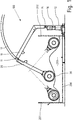
- FIG. 1 shows a roller compactor 100 for compacting waste materials 203.
- a container 200 has a front end wall 201 and a rear end wall 202. The line in the container 200 identifies the upper side of waste materials 203 which are stacked therein.
- a stand 16 of the roller compactor 100 is arranged behind the rear end wall 202 and extends with runners jumping forward to below the bottom of the container 200 in order to improve the support.
- a support arm 10 is connected to the stand 12 via a joint 15.
- a pendulum arm 20 is connected via a joint 11. No actuators are provided between the support arm 10 and the pendulum arm 20, so that the pendulum arm 20 can pivot freely about the joint 11.
- a gear holder element 25 is attached, which contains, among other things, bearing elements and a gear for a roller unit 30 in order to drive a roller 11.
- Lift cylinder is also a here between the tripod 12 and the support arm 10
- Lift cylinder is provided as an actuator in order to be able to raise and lower the support arm 10. With the lifting and lowering of the support arm 10, the joint 11 moves on an arc 17.
- the invention relates in particular to the pendulum arm 20 together with the roller unit 30 of the roller compactor 100.
- the pendulum arm 20 is in Figure 2 shown separately, namely in a view from above onto a central axis 36 of the roller unit 30.
- the pendulum arm 20 comprises two outer carrier profiles 22 which connect to a common head element 26 which has bearing mounts 21 for forming the pivot bearing 11.
- a common foot element 23 which is hollow and receives an electric motor 41 inside.
- the foot element 23 has a connecting flange 24 on the side facing away from the carrier profiles 22, to which the gear holder element 25 is fastened.
- the pendulum arm 20 has a motor unit 40 which, in addition to the electric motor 41, has a compensating clutch 42, a drive shaft 43 and an in Fig. 2 has invisible plug coupling.
- the roller unit 30 comprises the roller bodies 31, 32, which are fastened to flanges 33, 57 of an output shaft 25.
- the two roller bodies 31, 32 together form an almost continuous cylinder body, in the Inside, part of the gear holder element 25 is received, to which the gear 50 is in turn attached.
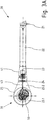
- Figure 3A shows the pendulum arm 20 with the roller unit 30 in a side view. From this, in particular, the contour of the gear holder element 25 with an annular disk-shaped area 25. 1, which extends around a central recess to which the gear 50 is attached, becomes clear.
- the annular disk-shaped area 25.1 runs towards the pendulum arm 20 in a trapezoidal area 25.2.
- the gear holder element 25 is in Figure 6 shown individually in a perspective view.
- the annular disk-shaped area 25.1 and the trapezoidal area 25.2 are formed from two sheet metal blanks 25.10, 25.11, of which the sheet metal blank 25.11 has a flange for the gearbox and the sheet metal blank 25.11 lying thereon is recessed somewhat further so that the gearbox housing can be attached to the flange unhindered.
- Ring-shaped webs 25.9 are attached to area 25.1 on both sides. These protrude into the inner, hollow part of the roller body in order to cover the gap between the roller body and gear holder element 25.
- the annular disk-shaped area 25.1 includes a recess 25.8 for receiving the gear.
- the recess 25.8 continues in the trapezoidal region 25.2 as a narrow recess 25.7 in which the drive shaft can be received.
- the end of the trapezoidal area 25.2 is closed by a flange plate 25.4, which contains a recess 25.5 for the passage of the drive shaft.
- Reinforcing plates 25.3 serve to reinforce the gear holder element 25 against bending forces which act between the pendulum arm 12 and the roller unit 30.
- FIG 3B is off as an enlargement Figure 3 the roller unit 30 with the gear 50 is shown in detail.
- the drive shaft 43 runs from the motor 41 via a compensating coupling 42, such as a claw coupling, to a plug-in coupling 44. If the roller unit 30 has to be replaced for maintenance purposes, only a mechanical connection is required be solved on the flange 24. The roller unit 30 can then be completely removed from the pendulum arm 20 without the motor 41 or control and / or power supply lines leading there having to be released. Nothing needs to be removed from the roller unit 50 either. In the later assembly, only the end of the drive shaft 43 has to be inserted into the plug-in coupling 44 on the gear 50 and the connection on the flange 24 must be restored.
- the gear 50 receives the output shaft 57 and also has bearings therefor, so that the output shaft 57 and the gear 50 form a unit.
- the satellite-shaped arrangement of the gear stages 51, 52, 53 around the central output shaft 57 is characteristic of the preferred embodiment of the invention.
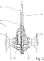
- Figure 4 shows a side view of a gear 50.
- the gear 50 has two housing halves 58.1, 58.2 which are screwed together. The parting plane between them coincides with the central axis of the drive shaft 43.
- the dashed lines indicate the position of the gear holder element 25, which essentially consists of two sheet metal blanks, the connection plane of which corresponds to the said parting plane and the central axis.
- Parts of the output shaft 57 protrude from the housing of the transmission 50 on both sides.
- the ends of each are provided with a flange 33, 34, to which the roller bodies are later attached.
- FIG. 5 shows a detail of the plug-in coupling 44 on the transmission 50.
- a short entry shaft 59 protrudes from the top of the transmission housing.
- the plug-in coupling 44 has at least one form-locking means such as a key 44.1 for torque transmission to the shafts 43, 59. Otherwise, only sealing rings are provided in the plug-in coupling 44 in order to avoid the ingress of dirt. Appropriate shaping at the ends of the shafts 43, 59 prevents an excessive axial Change of position of the plug coupling.
- a positive or non-positive locking between the ends of the shafts 43, 59 and the plug-in coupling 44 in the axial direction is not provided in order to facilitate the assembly and disassembly of the roller unit 30 on or from the pendulum arm 20.
Abstract
Ein Pendelarm (20) für einen Walzenverdichter (100) zum Verdichten von Abfallstoffen (203) in einem oben offenen Container (200) umfasst eine Walzeneinheit (30), die an einem Getriebehalterelement (25) mit am Ende des Pendelarms (20) angeordnet ist und die wenigstens zwei rotierbare Walzenkörper (31, 32) besitzt, welche beidseits des Getriebehalterelements (25) angeordnet sind, innen wenigstens teilweise hohl ausgebildet sind und eine Abtriebswelle (57) und deren Lager wenigstens teilweise umschließen.Eine Motoreinheit (40) enthält einen Elektromotor (41), der am Pendelarm (20) angeordnet ist und der über ein Übertragungselement mit einem Getriebe (50) verbunden ist. Das Getriebe (50) ist innerhalb der Walzenkörper (31, 32) angeordnet. Es ist am Getriebehalterelement (25) befestigt oder in das Getriebehalterelement (25) integriert.A pendulum arm (20) for a roller compactor (100) for compacting waste materials (203) in a container (200) which is open at the top comprises a roller unit (30) which is arranged on a gear holder element (25) at the end of the pendulum arm (20) and which has at least two rotatable roller bodies (31, 32) which are arranged on both sides of the gear holder element (25), are at least partially hollow on the inside and at least partially enclose an output shaft (57) and its bearings. One motor unit (40) contains an electric motor (41) which is arranged on the pendulum arm (20) and which is connected to a transmission (50) via a transmission element. The gear (50) is arranged inside the roller body (31, 32). It is attached to the gear holder element (25) or integrated into the gear holder element (25).
Description
Die Erfindung betrifft einen Pendelarm für einen Walzenverdichter zum Verdichten von Abfallstoffen in einem oben offenen Container, mit den Merkmalen des Oberbegriffs des Anspruchs 1.The invention relates to a pendulum arm for a roller compactor for compacting waste materials in an open container, with the features of the preamble of claim 1.
Ein Walzenverdichter wurde von der Anmelderin erstmals in der
In weiteren Fortentwicklungen, wie sie beispielsweise in der
Der Antrieb der Walzenkörper erfolgt bisher über einen Hydromotor. Dazu muss eine leistungsstarke Hydraulikpumpe neben dem ortsfesten Teil des Walzenverdichters aufgestellt werden. Eine Hydraulikleitung wird von dort über den zweiteiligen Knickarm, von dem der Pendelarm einen Endabschnitt bildet, bis zum dem Hydromotor im Inneren der Walzeneinheit geführt. Entsprechend der großen Länge der hydraulischen Zu- und Ablaufleitungen muss ein großes Volumen an Hydraulikflüssigkeit vorrätig gehalten und im Betrieb umgewälzt werden. Bei einer Drehrichtungsumkehr der Walzenkörper werden Drosselventile benötigt, um den Nachlauf zu bremsen. Aufgrund der großen Trägheitsmomente, die von den Walzenkörpern ausgehen, werden diese zudem stark belastet. Die Hydraulikflüssigkeit erwärmt sich entsprechend, wodurch die Viskosität sinkt und die über die Walzeneinheit in die Abfallschüttung *□□einbringbare Leistung sinkt. Daher muss entweder eine zusätzliche Temperierung im Ölkreislauf vorgesehen werden, oder es sind regelmäßige Betriebsunterbrechungen zur Abkühlung erforderlich. Gerade bei der Verwendung des Walzenverdichters in Recyclinghöfen in der Nähe von Wohngebieten wirkt die Geräuschentwicklung des Hydraulikaggregates störend. Schließlich ist die Montage oder Demontage der Walzeneinheit zeitaufwändig, da unter anderem der Ölkreislauf entleert bzw. befüllt werden muss, bevor die Hydraulikleitungen entfernt werden können und die mechanische Verbindung der Walzeneinheit gelöst werden kann.Up to now, the roller bodies have been driven by a hydraulic motor. To do this, a powerful hydraulic pump must be installed next to the stationary part of the roller compactor. A hydraulic line is led from there via the two-part articulated arm, of which the pendulum arm forms an end section, to the hydraulic motor inside the roller unit. Due to the large length of the hydraulic inlet and outlet lines, a large volume of hydraulic fluid must be kept in stock and circulated during operation. If the direction of rotation of the roller body is reversed, throttle valves are required to brake the overrun. Due to the large moments of inertia emanating from the roller bodies, these are also heavily loaded. The hydraulic fluid heats up accordingly, which lowers the viscosity and reduces the output that can be introduced into the waste bed * □□ via the roller unit. For this reason, additional temperature control in the oil circuit must be provided, or regular interruptions to the cooling process are required. Especially when using the roller compactor in recycling yards near residential areas, the noise generated by the hydraulic unit is disruptive. Finally, the assembly or disassembly of the roller unit is time-consuming since, among other things, the oil circuit must be emptied or filled before the hydraulic lines can be removed and the mechanical connection of the roller unit can be released.
Die Aufgabe der Erfindung besteht somit darin, einen Pendelarm der eingangs genannten Art so zu verbessern, dass die genannten Nachteile beim Antrieb der Walze beseitigt werden.The object of the invention is therefore to improve a pendulum arm of the type mentioned in such a way that the disadvantages mentioned when driving the roller are eliminated.
Diese Aufgabe wird durch einen Pendelarm für einen Walzenverdichter mit den Merkmalen des Anspruchs 1 gelöst.This object is achieved by a pendulum arm for a roller compactor with the features of claim 1.
Dieser Pendelarm ist eine autarke Einheit, so dass er gut zur Umrüstung vorhandener Walzenverdichter eingesetzt werden kann. Zusammen mit einem Stativ und einem wenigstens einteiligen Tragarm bildet er einen kompletten Walzenverdichter.This pendulum arm is a self-sufficient unit, so that it can be used to convert existing roller compactors. Together with a tripod and an at least one-piece support arm, it forms a complete roller compactor.
Der Vorteil besteht insbesondere in der Verwendung eines elektrischen Antriebs, wobei der Motor im Pendelarm angeordnet ist und in der Walzeneinheit ein Getriebe zur Herabsetzung der Drehzahl ausgebildet ist. Da ein Elektromotor der erforderlichen Leistungsklasse von etwa 3 bis 7,5 kW für eine Drehzahl von etwa 1500 min-1 ausgelegt ist, jedoch die Walzenkörper mit circa 6 bis 15 min-1 sehr langsam laufen, ist eine starke Untersetzung im Getriebe erforderlich.The advantage is in particular the use of an electric drive, the motor being arranged in the pendulum arm and a gear mechanism in the roller unit for reducing the speed. Since an electric motor of the required performance class of approximately 3 to 7.5 kW is designed for a speed of approximately 1500 min-1, but the roller bodies run very slowly with approximately 6 to 15 min-1, a strong reduction in the gearbox is required.
Die Umrüstung auf einen elektrischen Antrieb hat den Vorteil, dass nur eine elektrische Steuer- und Versorgungsleitung durch den Knickarm bis zur Walze geführt zu werden braucht, welche schon allein einen kleineren Querschnitt hat als eine der beiden Hydraulikleitungen im Stand der Technik. Über einen Frequenzumrichter kann die Drehzahl der Walze während des Betriebs angepasst werden. Erstmalig ist bei einem Walzenverdichter eine Messung der momentanen Antriebsleistung möglich, durch welche in einer Steuerungseinheit Rückschlüsse auf das gerade bearbeitete Gut gezogen werden können und der Bearbeitungsgang des Walzenverdichters im laufenden Betrieb angepasst werden kann.The conversion to an electric drive has the advantage that only one electrical control and supply line needs to be led through the articulated arm to the roller, which already has a smaller cross section than one of the two hydraulic lines in the prior art. The speed of the roller can be adjusted during operation using a frequency converter. For the first time, a measurement of the current drive power is possible with a roller compactor, by means of which a control unit can be used to draw conclusions about the material being processed and the processing step of the roller compactor can be adapted during operation.
Der Nachlauf der Walzenkörper beim Abschalten des Antriebs wird bereits durch das Getriebe reduziert. Zusätzlich kann in bekannter Weise am Elektromotor selbst gebremst werden. Aufgrund der festen Kopplung von Elektromotor und Getriebe kann in der Steuerung die momentane Drehzahl wie auch der Nachlauf der Walzenkörper leicht erfasst werden, ohne dass dafür Drehzahlsensoren notwendig wären.The overrun of the roller bodies when the drive is switched off is already reduced by the gear. In addition, braking can be carried out on the electric motor itself in a known manner. Due to the fixed coupling of the electric motor and gearbox, the current speed and the caster of the roller body can be easily recorded in the control system without the need for speed sensors.
Die besondere Herausforderung bei der Umrüstung einer Walzeneinheit für einen Walzenverdichter besteht darin, dass dieser nur ein sehr flaches Getriebehalterelement besitzen darf, das zwischen den Walzenkörpern anzuordnen ist und daher kaum mehr als eine doppelte Blechstärke dick sein darf. Das Getriebehalterelement ist so schmal wie möglich ausgebildet, damit die Unterbrechung zwischen den im Wesentlichen zylindrischen Walzenkörpern - und damit der Anteil der Umfangsfläche, über die der Walzenverdichter nicht auf die Abfälle einwirken kann - möglichst gering ist.The particular challenge when converting a roller unit for a roller compactor is that it may only have a very flat gear holder element which is to be arranged between the roller bodies and therefore may hardly be more than twice the sheet thickness. The gear holder element is designed to be as narrow as possible so that the interruption between the essentially cylindrical roller bodies - and thus the proportion of the peripheral surface over which the roller compactor cannot act on the waste - is as small as possible.
Eine sich radial bis zur Walzenaußenseite erstreckende und - von außen gesehen - axial zwischen den Walzenkörpern angeordnete Antriebs- und Getriebeeinheit wäre zu breit und würde zu Störungen bei der Abfallbearbeitung führen, weil in dem nicht rotierenden Bereich zwischen den Walzen Abfall nicht erfasst werden könnte.A drive and gear unit which extends radially up to the outside of the roll and - seen from the outside - is arranged axially between the roll bodies would be too wide and would lead to malfunctions in waste processing because waste could not be detected in the non-rotating area between the rolls.
Daher sieht die Erfindung vor, dass bis auf die schmalen randseitigen Abschnitte des Getriebehalterelements, die zwischen den Walzenkörpern herausragen müssen, um einen Anschluss an den Pendelarm herzustellen, alle Teile des Getriebes innerhalb des jeweiligen Hohlraums der benachbarten Walzenkörper untergebracht werden. Dies sind unter anderem die Abtriebswelle, die Lager dafür, sowie Flansche, an denen die Walzenkörper befestigt sind. Für die Unterbringung eines herkömmlichen Elektromotors mit angeflanschtem Getriebe bleibt innerhalb des Hohlraums der Walzenkörper zu wenig Bauraum übrig.Therefore, the invention provides that except for the narrow edge-side portions of the gear holder element, which must protrude between the roller bodies in order to establish a connection to the pendulum arm, all parts of the gear mechanism are accommodated within the respective cavity of the adjacent roller bodies. These include the output shaft, the bearings for it, and flanges to which the roller bodies are attached. To accommodate a conventional electric motor with a flange-mounted gearbox, there is not enough installation space inside the roller body.
Außerdem besteht eine spezifische Anforderung bei einem Pendelarm für einen symmetrisch aufgebauten Walzenverdichter mit Walzenkörpern beidseits des Getriebehalterelements darin, dass die Masseverteilung in Bezug auf eine durch das Getriebehalterelement verlaufende Achse ausgewogen sein muss. Denn der Pendelarm arbeitet frei am Tragarm hängend nur über die Rotation der Walze. Es können also über den Knickarm, von dem der Pendelarm einen Teil bildet, keine seitlichen Abstützkräfte aufgebracht werden. Eine falsche Massenverteilung in der Walzeneinheit führt zu einer seitlichen Biegemomentbelastung des Schwenkgelenks zwischen Pendelarm und Tragarm, das für solche Belastungen nicht ausgelegt werden kann, ohne die Grundkonstruktion des Walzenverdichters vollständig zu ändern.In addition, a specific requirement for a pendulum arm for a symmetrically constructed roller compactor with roller bodies on both sides of the gear holder element is that the mass distribution must be balanced with respect to an axis running through the gear holder element. Because the pendulum arm works freely hanging on the support arm only via the rotation of the roller. No lateral support forces can therefore be applied via the articulated arm, of which the pendulum arm forms a part. An incorrect mass distribution in the roller unit leads to a lateral one Bending moment load on the swivel joint between the pendulum arm and the support arm, which cannot be designed for such loads without completely changing the basic construction of the roller compactor.
Daher sieht die erfindungsgemäße Lösung vor, den Elektromotor nicht in der Walzeneinheit, sondern im Pendelarm anzuordnen und zwar achsparallel zu oder sogar fluchtend mit dessen Mittelachse, und außerdem möglichst tief am Pendelarm. Das Getriebe wird vom Motor abgesetzt innerhalb wenigstens eines Hohlraums in den Walzenkörpern angeordnet und bildet mit dem Getriebehalterelement eine hinsichtlich der Massenverteilung ebenfalls ausgewogene Einheit.Therefore, the solution according to the invention provides for the electric motor not to be arranged in the roller unit, but rather in the pendulum arm, namely axially parallel to or even flush with its central axis, and also as low as possible on the pendulum arm. The gear is placed away from the motor within at least one cavity in the roller bodies and forms with the gear holder element a unit that is also balanced with regard to the mass distribution.
Weiterhin sieht die Erfindung vor, das Getriebe an einem Flansch, der sich um eine zentrale Ausnehmung im Getriebehalterelement herum erstreckt, zu befestigen. Das Getriebe ist damit genau zentral in der Walzeneinheit positioniert.Furthermore, the invention provides for the transmission to be fastened to a flange which extends around a central recess in the transmission holder element. The gearbox is thus positioned exactly in the center of the roller unit.
Möglich ist auch, das Getriebe und den zwischen den Walzenkörpern befindlichen Teil des Getriebehalterelements zu einer Einheit zu verschmelzen, also beispielsweise das Getriebehalterelement als eine Hälfte eines Getriebegehäuses auszubilden.It is also possible to fuse the transmission and the part of the transmission holder element located between the roller bodies into one unit, that is to say, for example, to design the transmission holder element as one half of a transmission housing.
Die Übertragung der Antriebsleistung zwischen Motor und Getriebe erfolgt bevorzugt über eine Antriebswelle. Angesichts der meist erforderlichen starken Untersetzung im Getriebe ist das antriebsseitige Drehmoment eher gering, so dass die Antriebswelle insbesondere so dünn ausgebildet werden kann, dass sie in einer Aussparung in dem flächigen Teil des Getriebehalterelements geführt werden kann, ohne seitlich aus diesem heraus zu ragen. Diese Führung der Antriebswelle betrifft insbesondere den Abschnitt des Getriebehalterelements zwischen dem Ende des Pendelarms und dem Eintritt in die Walzeneinheit zwischen den Walzenkörpern.The drive power is transmitted between the engine and the transmission preferably via a drive shaft. In view of the strong reduction required in the transmission, the drive-side torque is rather low, so that the drive shaft can in particular be made so thin that it can be guided in a recess in the flat part of the transmission holder element without projecting laterally out of it. This guidance of the drive shaft relates in particular to the section of the gear holder element between the end of the pendulum arm and the entry into the roller unit between the roller bodies.
Um die meist notwendige hohe Untersetzung erzielen zu können, ist eine besonders platzsparende Bauweise des Getriebes notwendig, da ja nur ein begrenzter Öffnungsquerschnitt innerhalb des Hohlraums der Walzenkörper zur Verfügung steht. Als erste Maßnahme wird bei einer bevorzugten Ausführungsform eines Getriebes ein erstes Zahnrad direkt mit der durchgängigen Abtriebswelle verbunden, welche durch das Getriebe und das Getriebehalterelement hindurchführt, und zwar werden das Stirnrad wie auch das dort eingreifende Ritzel zwischen den Lagern der Abtriebswelle positioniert.In order to be able to achieve the mostly necessary high reduction, a particularly space-saving construction of the gearbox is necessary, since only one limited opening cross-section is available within the cavity of the roller body. As a first measure, in a preferred embodiment of a transmission, a first gearwheel is connected directly to the continuous output shaft which passes through the transmission and the transmission holder element, specifically the spur gear and the pinion engaging there are positioned between the bearings of the output shaft.
Weiterhin wird bevorzugt ein Kegelradpaar im radialen Randbereich des Getriebegehäuses angeordnet. Die Rotation der Antriebswelle wird bereits dort um 90° umgelenkt, so dass alle folgenden Getriebestufen im Getriebe achsparallel zur Abtriebswelle ausgerichtet werden können.Furthermore, a pair of bevel gears is preferably arranged in the radial edge region of the gear housing. The rotation of the drive shaft is already deflected there by 90 °, so that all subsequent gear stages in the gear can be aligned axially parallel to the output shaft.
Die Getriebestufen besitzen vorzugsweise jeweils ein Zahnrad und ein Ritzel auf einer gemeinsamen Welle. Zahnrad und Ritzel sind jeweils abwechselnd auf verschiedenen Seiten der durch das Getriebehalterelement definierten Mittelebene positioniert.The gear stages preferably each have a gear and a pinion on a common shaft. The gear and pinion are alternately positioned on different sides of the central plane defined by the gear holder element.
Die bevorzugte Ausführungsform der Erfindung sieht eine satellitenförmige Anordnung der Getriebestufen vor, das heißt, diese sind in dem Ringraum zwischen dem Außenumfang der Abtriebswelle und dem Innenumfang des Hohlraums in den Walzenkörpern nebeneinander angeordnet. "Nebeneinander" bedeutet hierbei nicht die Anordnung in linearer Weise, sondern - in der Seitenansicht auf das Getriebe gesehen - entlang eines bogenförmigen oder sonstwie gekrümmten Pfades. Nach der Erfindung erstreckt sich beispielsweise bei einem Getriebe mit drei Untersetzungsstufen diese Anordnung zwischen der ersten Getriebestufe, welche direkt an der Abtriebswelle angreift, und der Eintrittsöffnung am Getriebegehäuse für die Antriebswelle über ca. 60° bis 80°. Von der möglichen radialen Ausdehnung innerhalb des Walzenkörpers werden von dem genannten Sektor des Getriebes mit den satellitenförmig angeordneten Getriebestufen nur etwa 50% bis 80% belegt. Entsprechend verbleibt ein ausreichend breiter, ringförmiger Bereich am Getriebehalterelement, der sich um die zentrale Ausnehmung herum erstreckt, um die Festigkeit des Getriebehalterelements nicht zu gefährden.The preferred embodiment of the invention provides a satellite-shaped arrangement of the gear stages, that is to say they are arranged side by side in the annular space between the outer periphery of the output shaft and the inner periphery of the cavity in the roller bodies. "Side by side" here does not mean the arrangement in a linear manner, but - seen in the side view of the gearbox - along an arcuate or otherwise curved path. According to the invention, for example in the case of a transmission with three reduction stages, this arrangement extends between the first transmission stage, which acts directly on the output shaft, and the inlet opening on the transmission housing for the drive shaft over approximately 60 ° to 80 °. Of the possible radial expansion within the roller body, only about 50% to 80% are occupied by the sector of the transmission mentioned with the satellite-arranged gear stages. Accordingly, a sufficiently wide, annular area remains on the gear holder element, which extends around the central recess, in order not to endanger the strength of the gear holder element.
Die Erfindung wird nachfolgend anhand eines Ausführungsbeispiels, das in den Zeichnungen dargestellt ist, näher erläutert. Die Figuren zeigen im Einzelnen:
- Fig. 1
- einen Walzenverdichter zur Verdichtung von Abfallstoffen in seitlicher Ansicht;
- Figur 2
- einen erfindungsgemäßen Pendelarm mit Walzeneinheit in Ansicht von oben;
- Figur 3A
- den Pendelarm mit Walzeneinheit in seitlicher Ansicht;
- Figur 3B
- ein vergrößertes Details aus
Figur 3A ; - Figur 4
- eine seitliche Ansicht auf ein Getriebe mit Blick auf die Mittelebene;
- Figur 5
- eine Steckkupplung am Getriebe im Schnitt; und
- Figur 6
- ein Getriebehalterelement in perspektivischer Ansicht.
- Fig. 1
- a roller compactor for compacting waste materials in a side view;
- Figure 2
- a pendulum arm according to the invention with roller unit in a view from above;
- Figure 3A
- the pendulum arm with roller unit in a side view;
- Figure 3B
- an enlarged detail
Figure 3A ; - Figure 4
- a side view of a transmission with a view of the central plane;
- Figure 5
- a plug-in coupling on the gearbox in section; and
- Figure 6
- a gear holder element in a perspective view.
In
Die Erfindung bezieht sich insbesondere auf den Pendelarm 20 samt Walzeneinheit 30 des Walzenverdichters 100. Der Pendelarm 20 ist in
Der Pendelarm 20 nach der Erfindung besitzt eine Motoreinheit 40, die neben dem Elektromotor 41 eine Ausgleichskupplung 42, eine Antriebswelle 43 und eine in
Die Walzeneinheit 30 umfasst die Walzenkörper 31, 32, die an Flanschen 33, 57 einer Abtriebswelle 25 befestigt sind. Die beiden Walzenkörper 31, 32 bilden zusammen einen nahezu ununterbrochenen Zylinderkörper, in dessen Innerem ein Teil des Getriebehalterelements 25 aufgenommen ist, an dem wiederum das Getriebe 50 befestigt ist.The
Das Getriebehalterelement 25 ist in
In
Das Getriebe 50 nimmt die Abtriebswelle 57 auf und besitzt auch Lagerungen dafür, so dass die Abtriebswelle 57 und das Getriebe 50 eine Einheit bilden. An der Außenseite des Gehäuses des Getriebes 50 sind aufgrund der dort angebrachten Wartungsdeckel insgesamt drei Getriebestufen 51, 52, 53 von außen erkennbar. Charakteristisch für die bevorzugte Ausführungsform der Erfindung ist die satellitenförmige Anordnung der Getriebestufen 51, 52, 53 um die zentrale Abtriebswelle 57 herum.The
Claims (10)
wenigstens umfassend:
at least comprehensive:
Applications Claiming Priority (1)
| Application Number | Priority Date | Filing Date | Title |
|---|---|---|---|
| DE102019100001.7A DE102019100001A1 (en) | 2019-01-01 | 2019-01-01 | Pendulum arm for a roller compactor for compacting waste materials in an open container |
Publications (2)
| Publication Number | Publication Date |
|---|---|
| EP3677351A1 true EP3677351A1 (en) | 2020-07-08 |
| EP3677351B1 EP3677351B1 (en) | 2022-12-14 |
Family
ID=69063640
Family Applications (1)
| Application Number | Title | Priority Date | Filing Date |
|---|---|---|---|
| EP19220033.5A Active EP3677351B1 (en) | 2019-01-01 | 2019-12-30 | Pendulum arm for a roller compactor for compacting waste materials in a container with an open top |
Country Status (6)
| Country | Link |
|---|---|
| EP (1) | EP3677351B1 (en) |
| DE (1) | DE102019100001A1 (en) |
| DK (1) | DK3677351T3 (en) |
| ES (1) | ES2938686T3 (en) |
| FI (1) | FI3677351T3 (en) |
| PL (1) | PL3677351T3 (en) |
Citations (4)
| Publication number | Priority date | Publication date | Assignee | Title |
|---|---|---|---|---|
| DE3023508C1 (en) | 1980-06-24 | 1981-12-10 | Heinz 4474 Lathen Bergmann | Device for compacting waste consisting of packaging material and easily compressible waste |
| EP0106268A1 (en) * | 1982-10-15 | 1984-04-25 | Heinz Bergmann | Compacting device for garbage consisting of packing material and easily compressable waste material |
| DE202011000241U1 (en) | 2011-02-01 | 2011-06-01 | Heinz Bergmann Maschine für die Abfallwirtschaft e.K., 49762 | Roll compactor device for compacting waste and valuable materials |
| EP2808161A1 (en) * | 2013-05-31 | 2014-12-03 | Heinz Bergmann e.Kfm. Maschinen für die Abfallwirtschaft | Roller compressor device for compacting waste materials and recyclable material |
-
2019
- 2019-01-01 DE DE102019100001.7A patent/DE102019100001A1/en active Pending
- 2019-12-30 EP EP19220033.5A patent/EP3677351B1/en active Active
- 2019-12-30 PL PL19220033.5T patent/PL3677351T3/en unknown
- 2019-12-30 ES ES19220033T patent/ES2938686T3/en active Active
- 2019-12-30 DK DK19220033.5T patent/DK3677351T3/en active
- 2019-12-30 FI FIEP19220033.5T patent/FI3677351T3/en active
Patent Citations (4)
| Publication number | Priority date | Publication date | Assignee | Title |
|---|---|---|---|---|
| DE3023508C1 (en) | 1980-06-24 | 1981-12-10 | Heinz 4474 Lathen Bergmann | Device for compacting waste consisting of packaging material and easily compressible waste |
| EP0106268A1 (en) * | 1982-10-15 | 1984-04-25 | Heinz Bergmann | Compacting device for garbage consisting of packing material and easily compressable waste material |
| DE202011000241U1 (en) | 2011-02-01 | 2011-06-01 | Heinz Bergmann Maschine für die Abfallwirtschaft e.K., 49762 | Roll compactor device for compacting waste and valuable materials |
| EP2808161A1 (en) * | 2013-05-31 | 2014-12-03 | Heinz Bergmann e.Kfm. Maschinen für die Abfallwirtschaft | Roller compressor device for compacting waste materials and recyclable material |
Also Published As
| Publication number | Publication date |
|---|---|
| DE102019100001A1 (en) | 2020-07-02 |
| ES2938686T3 (en) | 2023-04-13 |
| EP3677351B1 (en) | 2022-12-14 |
| FI3677351T3 (en) | 2023-03-19 |
| DK3677351T3 (en) | 2023-02-13 |
| PL3677351T3 (en) | 2023-02-06 |
Similar Documents
| Publication | Publication Date | Title |
|---|---|---|
| DE3724126C2 (en) | Drive roller unit | |
| EP0443060B1 (en) | Driving roller unit | |
| EP0140009A1 (en) | Radial upsetting machine for work pieces with a cylindrical surface | |
| EP3405699B1 (en) | Actuator with a rigid-spined chain | |
| AT511833A4 (en) | MASTER CONSTRUCTION, ESPECIALLY FOR A AUTOBETON PUMP | |
| EP3775535B1 (en) | Large rolling bearing | |
| DE4242886A1 (en) | Device for adjusting a cutting knife bar for a cutting cylinder of a rotary printing press | |
| DE102005021460A1 (en) | Adjusting unit for clutch or transmission brake, comprises bearing element designed as carriage with three pairs of rollers | |
| DE4206101C2 (en) | Hydromechanical drive system | |
| DE3330204C2 (en) | Spur gear for driving a roll shell | |
| AT407186B (en) | Helical gearboxes for driving a roller sleeve | |
| EP3677351B1 (en) | Pendulum arm for a roller compactor for compacting waste materials in a container with an open top | |
| DE3728389C2 (en) | ||
| AT520549B1 (en) | Hydraulic rotary drive | |
| DE3322350C1 (en) | Crane bottom block with rotary drive | |
| EP1018416B1 (en) | Roll mill for raw materials in the ceramic industry | |
| DE3141039C2 (en) | Device for moving rod-shaped goods, such as pipes, shafts and wire, in the direction of its longitudinal axis, in particular as a pulling or pulling device for peeling and / or straightening machines | |
| DE3038587C2 (en) | Drivable roller with controllable deflection, in particular for machines for producing and processing webs made of paper or plastic | |
| EP2329161B1 (en) | Universal joint arrangement for an articulated shaft | |
| DE202005011280U1 (en) | Lifting/swivelling device for hydraulic platform or loading ramp of vehicle, has swivel drive formed from two hydraulic motors having motor shaft rotatably supported in housing, where shaft stays in screw-contact with drive part | |
| DE102008058304B4 (en) | driving device | |
| DE3804225C2 (en) | ||
| DE19651769C2 (en) | Collection or folding cylinder with sliding cam | |
| EP0924338B1 (en) | Drive unit with a moving torque support for rolls | |
| DE102005039134A1 (en) | Clutch and brake device |
Legal Events
| Date | Code | Title | Description |
|---|---|---|---|
| PUAI | Public reference made under article 153(3) epc to a published international application that has entered the european phase |
Free format text: ORIGINAL CODE: 0009012 |
|
| STAA | Information on the status of an ep patent application or granted ep patent |
Free format text: STATUS: THE APPLICATION HAS BEEN PUBLISHED |
|
| AK | Designated contracting states |
Kind code of ref document: A1 Designated state(s): AL AT BE BG CH CY CZ DE DK EE ES FI FR GB GR HR HU IE IS IT LI LT LU LV MC MK MT NL NO PL PT RO RS SE SI SK SM TR |
|
| AX | Request for extension of the european patent |
Extension state: BA ME |
|
| STAA | Information on the status of an ep patent application or granted ep patent |
Free format text: STATUS: REQUEST FOR EXAMINATION WAS MADE |
|
| 17P | Request for examination filed |
Effective date: 20210108 |
|
| RBV | Designated contracting states (corrected) |
Designated state(s): AL AT BE BG CH CY CZ DE DK EE ES FI FR GB GR HR HU IE IS IT LI LT LU LV MC MK MT NL NO PL PT RO RS SE SI SK SM TR |
|
| GRAP | Despatch of communication of intention to grant a patent |
Free format text: ORIGINAL CODE: EPIDOSNIGR1 |
|
| STAA | Information on the status of an ep patent application or granted ep patent |
Free format text: STATUS: GRANT OF PATENT IS INTENDED |
|
| INTG | Intention to grant announced |
Effective date: 20220621 |
|
| GRAS | Grant fee paid |
Free format text: ORIGINAL CODE: EPIDOSNIGR3 |
|
| GRAA | (expected) grant |
Free format text: ORIGINAL CODE: 0009210 |
|
| STAA | Information on the status of an ep patent application or granted ep patent |
Free format text: STATUS: THE PATENT HAS BEEN GRANTED |
|
| AK | Designated contracting states |
Kind code of ref document: B1 Designated state(s): AL AT BE BG CH CY CZ DE DK EE ES FI FR GB GR HR HU IE IS IT LI LT LU LV MC MK MT NL NO PL PT RO RS SE SI SK SM TR |
|
| REG | Reference to a national code |
Ref country code: GB Ref legal event code: FG4D Free format text: NOT ENGLISH |
|
| REG | Reference to a national code |
Ref country code: CH Ref legal event code: EP |
|
| REG | Reference to a national code |
Ref country code: DE Ref legal event code: R082 Ref document number: 502019006520 Country of ref document: DE Representative=s name: TARVENKORN WICKORD & PARTNER PATENTANWAELTE PA, DE Ref country code: DE Ref legal event code: R082 Ref document number: 502019006520 Country of ref document: DE Representative=s name: TARVENKORN & WICKORD PATENTANWAELTE PARTG MBB, DE Ref country code: DE Ref legal event code: R082 Ref document number: 502019006520 Country of ref document: DE Representative=s name: BOEHMERT & BOEHMERT ANWALTSPARTNERSCHAFT MBB -, DE |
|
| REG | Reference to a national code |
Ref country code: DE Ref legal event code: R096 Ref document number: 502019006520 Country of ref document: DE |
|
| REG | Reference to a national code |
Ref country code: IE Ref legal event code: FG4D Free format text: LANGUAGE OF EP DOCUMENT: GERMAN |
|
| REG | Reference to a national code |
Ref country code: AT Ref legal event code: REF Ref document number: 1537367 Country of ref document: AT Kind code of ref document: T Effective date: 20230115 |
|
| REG | Reference to a national code |
Ref country code: NL Ref legal event code: FP |
|
| REG | Reference to a national code |
Ref country code: DK Ref legal event code: T3 Effective date: 20230209 |
|
| REG | Reference to a national code |
Ref country code: SE Ref legal event code: TRGR |
|
| REG | Reference to a national code |
Ref country code: NO Ref legal event code: T2 Effective date: 20221214 |
|
| REG | Reference to a national code |
Ref country code: LT Ref legal event code: MG9D |
|
| REG | Reference to a national code |
Ref country code: ES Ref legal event code: FG2A Ref document number: 2938686 Country of ref document: ES Kind code of ref document: T3 Effective date: 20230413 |
|
| PG25 | Lapsed in a contracting state [announced via postgrant information from national office to epo] |
Ref country code: LT Free format text: LAPSE BECAUSE OF FAILURE TO SUBMIT A TRANSLATION OF THE DESCRIPTION OR TO PAY THE FEE WITHIN THE PRESCRIBED TIME-LIMIT Effective date: 20221214 |
|
| PGFP | Annual fee paid to national office [announced via postgrant information from national office to epo] |
Ref country code: ES Payment date: 20230209 Year of fee payment: 4 Ref country code: CH Payment date: 20230131 Year of fee payment: 4 |
|
| PG25 | Lapsed in a contracting state [announced via postgrant information from national office to epo] |
Ref country code: RS Free format text: LAPSE BECAUSE OF FAILURE TO SUBMIT A TRANSLATION OF THE DESCRIPTION OR TO PAY THE FEE WITHIN THE PRESCRIBED TIME-LIMIT Effective date: 20221214 Ref country code: LV Free format text: LAPSE BECAUSE OF FAILURE TO SUBMIT A TRANSLATION OF THE DESCRIPTION OR TO PAY THE FEE WITHIN THE PRESCRIBED TIME-LIMIT Effective date: 20221214 Ref country code: HR Free format text: LAPSE BECAUSE OF FAILURE TO SUBMIT A TRANSLATION OF THE DESCRIPTION OR TO PAY THE FEE WITHIN THE PRESCRIBED TIME-LIMIT Effective date: 20221214 Ref country code: GR Free format text: LAPSE BECAUSE OF FAILURE TO SUBMIT A TRANSLATION OF THE DESCRIPTION OR TO PAY THE FEE WITHIN THE PRESCRIBED TIME-LIMIT Effective date: 20230315 |
|
| PGFP | Annual fee paid to national office [announced via postgrant information from national office to epo] |
Ref country code: PL Payment date: 20221229 Year of fee payment: 4 Ref country code: BE Payment date: 20230125 Year of fee payment: 4 |
|
| P01 | Opt-out of the competence of the unified patent court (upc) registered |
Effective date: 20230530 |
|
| PG25 | Lapsed in a contracting state [announced via postgrant information from national office to epo] |
Ref country code: SM Free format text: LAPSE BECAUSE OF FAILURE TO SUBMIT A TRANSLATION OF THE DESCRIPTION OR TO PAY THE FEE WITHIN THE PRESCRIBED TIME-LIMIT Effective date: 20221214 Ref country code: RO Free format text: LAPSE BECAUSE OF FAILURE TO SUBMIT A TRANSLATION OF THE DESCRIPTION OR TO PAY THE FEE WITHIN THE PRESCRIBED TIME-LIMIT Effective date: 20221214 Ref country code: PT Free format text: LAPSE BECAUSE OF FAILURE TO SUBMIT A TRANSLATION OF THE DESCRIPTION OR TO PAY THE FEE WITHIN THE PRESCRIBED TIME-LIMIT Effective date: 20230414 Ref country code: EE Free format text: LAPSE BECAUSE OF FAILURE TO SUBMIT A TRANSLATION OF THE DESCRIPTION OR TO PAY THE FEE WITHIN THE PRESCRIBED TIME-LIMIT Effective date: 20221214 Ref country code: CZ Free format text: LAPSE BECAUSE OF FAILURE TO SUBMIT A TRANSLATION OF THE DESCRIPTION OR TO PAY THE FEE WITHIN THE PRESCRIBED TIME-LIMIT Effective date: 20221214 |
|
| PG25 | Lapsed in a contracting state [announced via postgrant information from national office to epo] |
Ref country code: SK Free format text: LAPSE BECAUSE OF FAILURE TO SUBMIT A TRANSLATION OF THE DESCRIPTION OR TO PAY THE FEE WITHIN THE PRESCRIBED TIME-LIMIT Effective date: 20221214 Ref country code: LU Free format text: LAPSE BECAUSE OF NON-PAYMENT OF DUE FEES Effective date: 20221230 Ref country code: IS Free format text: LAPSE BECAUSE OF FAILURE TO SUBMIT A TRANSLATION OF THE DESCRIPTION OR TO PAY THE FEE WITHIN THE PRESCRIBED TIME-LIMIT Effective date: 20230414 Ref country code: AL Free format text: LAPSE BECAUSE OF FAILURE TO SUBMIT A TRANSLATION OF THE DESCRIPTION OR TO PAY THE FEE WITHIN THE PRESCRIBED TIME-LIMIT Effective date: 20221214 |
|
| REG | Reference to a national code |
Ref country code: DE Ref legal event code: R097 Ref document number: 502019006520 Country of ref document: DE |
|
| PG25 | Lapsed in a contracting state [announced via postgrant information from national office to epo] |
Ref country code: MC Free format text: LAPSE BECAUSE OF FAILURE TO SUBMIT A TRANSLATION OF THE DESCRIPTION OR TO PAY THE FEE WITHIN THE PRESCRIBED TIME-LIMIT Effective date: 20221214 |
|
| PLBE | No opposition filed within time limit |
Free format text: ORIGINAL CODE: 0009261 |
|
| STAA | Information on the status of an ep patent application or granted ep patent |
Free format text: STATUS: NO OPPOSITION FILED WITHIN TIME LIMIT |
|
| PG25 | Lapsed in a contracting state [announced via postgrant information from national office to epo] |
Ref country code: IE Free format text: LAPSE BECAUSE OF NON-PAYMENT OF DUE FEES Effective date: 20221230 |
|
| 26N | No opposition filed |
Effective date: 20230915 |
|
| PG25 | Lapsed in a contracting state [announced via postgrant information from national office to epo] |
Ref country code: SI Free format text: LAPSE BECAUSE OF FAILURE TO SUBMIT A TRANSLATION OF THE DESCRIPTION OR TO PAY THE FEE WITHIN THE PRESCRIBED TIME-LIMIT Effective date: 20221214 |
|
| PGFP | Annual fee paid to national office [announced via postgrant information from national office to epo] |
Ref country code: GB Payment date: 20231220 Year of fee payment: 5 |
|
| PGFP | Annual fee paid to national office [announced via postgrant information from national office to epo] |
Ref country code: SE Payment date: 20231219 Year of fee payment: 5 Ref country code: NO Payment date: 20231218 Year of fee payment: 5 Ref country code: NL Payment date: 20231219 Year of fee payment: 5 Ref country code: FR Payment date: 20231219 Year of fee payment: 5 Ref country code: FI Payment date: 20231218 Year of fee payment: 5 Ref country code: DK Payment date: 20231219 Year of fee payment: 5 Ref country code: DE Payment date: 20231214 Year of fee payment: 5 |
|
| PGFP | Annual fee paid to national office [announced via postgrant information from national office to epo] |
Ref country code: PL Payment date: 20231227 Year of fee payment: 5 Ref country code: BE Payment date: 20231218 Year of fee payment: 5 |
|
| PG25 | Lapsed in a contracting state [announced via postgrant information from national office to epo] |
Ref country code: HU Free format text: LAPSE BECAUSE OF FAILURE TO SUBMIT A TRANSLATION OF THE DESCRIPTION OR TO PAY THE FEE WITHIN THE PRESCRIBED TIME-LIMIT; INVALID AB INITIO Effective date: 20191230 |
|
| REG | Reference to a national code |
Ref country code: DE Ref legal event code: R082 Ref document number: 502019006520 Country of ref document: DE Representative=s name: BOEHMERT & BOEHMERT ANWALTSPARTNERSCHAFT MBB -, DE |
|
| PGFP | Annual fee paid to national office [announced via postgrant information from national office to epo] |
Ref country code: ES Payment date: 20240118 Year of fee payment: 5 |