EP3676909B1 - Antenna for receiving data from low earth orbit satellites - Google Patents
Antenna for receiving data from low earth orbit satellites Download PDFInfo
- Publication number
- EP3676909B1 EP3676909B1 EP17854229.6A EP17854229A EP3676909B1 EP 3676909 B1 EP3676909 B1 EP 3676909B1 EP 17854229 A EP17854229 A EP 17854229A EP 3676909 B1 EP3676909 B1 EP 3676909B1
- Authority
- EP
- European Patent Office
- Prior art keywords
- antenna
- feed
- positioner
- arm
- rotation axis
- Prior art date
- Legal status (The legal status is an assumption and is not a legal conclusion. Google has not performed a legal analysis and makes no representation as to the accuracy of the status listed.)
- Active
Links
- 238000000034 method Methods 0.000 claims description 8
- 230000007246 mechanism Effects 0.000 description 6
- 238000012544 monitoring process Methods 0.000 description 5
- 238000004519 manufacturing process Methods 0.000 description 4
- 238000013461 design Methods 0.000 description 3
- 230000000694 effects Effects 0.000 description 3
- 238000002474 experimental method Methods 0.000 description 3
- 238000009434 installation Methods 0.000 description 3
- 238000012423 maintenance Methods 0.000 description 3
- 238000011900 installation process Methods 0.000 description 2
- 239000002184 metal Substances 0.000 description 2
- 238000001556 precipitation Methods 0.000 description 2
- 238000013341 scale-up Methods 0.000 description 2
- 238000009827 uniform distribution Methods 0.000 description 2
- 239000013585 weight reducing agent Substances 0.000 description 2
- 229920005372 Plexiglas® Polymers 0.000 description 1
- 230000003321 amplification Effects 0.000 description 1
- 238000004458 analytical method Methods 0.000 description 1
- 238000013459 approach Methods 0.000 description 1
- 238000004364 calculation method Methods 0.000 description 1
- 238000004891 communication Methods 0.000 description 1
- 238000010586 diagram Methods 0.000 description 1
- 230000003993 interaction Effects 0.000 description 1
- 238000012986 modification Methods 0.000 description 1
- 230000004048 modification Effects 0.000 description 1
- 238000003199 nucleic acid amplification method Methods 0.000 description 1
- 229920003023 plastic Polymers 0.000 description 1
- 239000004033 plastic Substances 0.000 description 1
- 239000004926 polymethyl methacrylate Substances 0.000 description 1
- 230000008569 process Effects 0.000 description 1
- 238000004088 simulation Methods 0.000 description 1
- 238000012546 transfer Methods 0.000 description 1
Images


Classifications
-
- H—ELECTRICITY
- H01—ELECTRIC ELEMENTS
- H01Q—ANTENNAS, i.e. RADIO AERIALS
- H01Q3/00—Arrangements for changing or varying the orientation or the shape of the directional pattern of the waves radiated from an antenna or antenna system
- H01Q3/12—Arrangements for changing or varying the orientation or the shape of the directional pattern of the waves radiated from an antenna or antenna system using mechanical relative movement between primary active elements and secondary devices of antennas or antenna systems
- H01Q3/16—Arrangements for changing or varying the orientation or the shape of the directional pattern of the waves radiated from an antenna or antenna system using mechanical relative movement between primary active elements and secondary devices of antennas or antenna systems for varying relative position of primary active element and a reflecting device
- H01Q3/18—Arrangements for changing or varying the orientation or the shape of the directional pattern of the waves radiated from an antenna or antenna system using mechanical relative movement between primary active elements and secondary devices of antennas or antenna systems for varying relative position of primary active element and a reflecting device wherein the primary active element is movable and the reflecting device is fixed
-
- H—ELECTRICITY
- H01—ELECTRIC ELEMENTS
- H01Q—ANTENNAS, i.e. RADIO AERIALS
- H01Q3/00—Arrangements for changing or varying the orientation or the shape of the directional pattern of the waves radiated from an antenna or antenna system
Definitions
- the present invention relates to a feed-motion antenna device and is designed for receiving Earth observation data streams from low Earth orbit satellites in space.
- Reflector antennae are the most widely used type of satellite antennae.
- a feed-motion antenna (with a movable reflector) is a widely used structure for a mechanical or electromechanical antenna for receiving signals from a satellite.
- this solution requires a complex mechanism for displacing the entire antenna structure.
- scanning can be accomplished by displacing a feed with a fixedly mounted antenna reflector.
- the disadvantage of the prior art antenna is that a complex system of cables and grips to support each cable is required.
- US 5751254 A discloses a feed movement mechanism and a control system for a multibeam antenna for tracking satellites from a geostationary orbit.
- feeds are moved along a non-planar focal surface of the antenna.
- the satellite can be tracked to some degree by moving the feed along the non-planar focal surface of the antenna on rails.
- the disadvantage of the prior art structure is that the antenna comprises two reflectors and several feeds, thus significantly increasing weight of the antenna structure.
- the antenna frame which provides a support structure for two reflectors and means for moving feeds further contributes to weight of the structure; furthermore, the frame is complex and difficult to assemble and install. It should further be noted that the received signal can contain noise when using several feeds.
- US 5714960 A discloses a parabolic antenna capable of allowing positioning of a feed horn at a focal point of a reflector by means of a frame and an arm and member for connecting the frame and the arm and adjusting an angle therebetween.
- CN 201838708 U discloses a rapidly erected and folded portable type paraboloid satellite receiving antenna comprising an antenna reflection panel, a feed source tuner assembly, and respective supporting and adjusting mechanisms thereof.
- the prior art antenna is compact, practical, easy to carry, and can be used in the field.
- the prior art antenna does not comprise automatic position re-tuning for the feed or antenna reflector; thus, the system requires an on-site visit by a specialist in order to redirect antenna to a different position. Furthermore, the feed moveability does not provide full use of the entire available antenna reflector aperture.
- the antenna system ( US 6204822 B1 ) for communicating between an Earth station and a satellite.
- the antenna system is used for communicating with low- and mid-earth orbiting satellites and comprises a broadband satellite communications system operating in the microwave and millimeter wave frequency bands.
- the antenna system employs one or more spherical reflectors (each a truncated spherical surface) and moveable feeds interacting therewith and providing mechanical scanning. The feed is driven by a two-axis positioner.
- the disadvantage of the prior art antenna is that positioner axes are arranged in several planes with respect to the reflector plane; therefore, controlling the positioner becomes more difficult when moving the feed, thus increasing the risk of scanning error. Furthermore, when one antenna is used, only a narrow section of satellite trajectory is scanned over a short time period due to the fact that the antenna reflector shape being a spherical reflector is characterized by significant height, and the positioner structure provides only partial surface exposure for the spherical reflector. When using several antenna reflectors, the structure weight increases and the process of installing the antenna system becomes more complex.
- the object of the present invention is to provide an easily mounted antenna for receiving data from low Earth orbit satellites, the antenna having a structure providing signal reception from the widest possible satellite trajectory section in standalone mode.
- an antenna for receiving data from low Earth orbit satellites comprising a fixedly mounted antenna reflector, a moveable feed, a feed positioner configured to move the feed in the focal plane of the antenna reflector, the feed positioned having a primary rotation axis and an auxiliary rotation axis, and a control device configured to send control signals to the feed positioner.
- the primary rotation axis of the feed positioner passes through the center of the antenna reflector and the primary rotation axis is perpendicular to the focal plane of the antenna reflector; the auxiliary rotation axis of the feed positioner is parallel to the primary rotation axis.
- the feed positioner comprises an equal-arm structure comprising a first arm and a second arm, and each arm is arranged in a plane perpendicular to the primary and auxiliary rotation axes.
- the first arm is connected at one its end to the primary rotation axis and adapted to be rotated around the primary rotation axis
- the feed is connected to an end of the second arm
- the first arm and the second arm are connected to each other at the auxiliary rotation axis and are adapted to be rotated with respect to each other.
- the diameter of the antenna reflector is at least 1.5 m
- the focal length of the antenna reflector is at least 1.0 m.
- the present invention provides a technologically simple, easily mounted structure providing a high quality data reception from the space by a long-focus antenna. Furthermore, the present invention contributes to a wider array of structures for antenna systems.
- the technical result is achieved by means of configuration of an antenna for receiving data from low Earth orbit satellites, wherein the primary rotation axis of the feed positioner passes through the center of the antenna reflector and is perpendicular to the focal plane of the antenna reflector; the auxiliary rotation axis of the feed positioner is parallel to the primary rotation axis; and the feed positioner comprises an equal-arm structure with each arm arranged in a plane perpendicular to the primary and auxiliary rotation axes, wherein the first arm is connected at one end to the primary rotation axis and adapted to be rotated around the primary axis, the feed is connected to an end of the second arm, wherein the first arm and the second arm are connected to each other at the auxiliary rotation axis and are adapted to be rotated with respect to each other; and wherein the diameter of the antenna reflector is at least 1.5 m, and the focal length of the antenna reflector is at least 1.0 m.
- the moving feed should be arranged in the focal plane of the antenna reflector.
- the focal plane of a wide-aperture long-focus reflector is generally parallel to the antenna plane, i.e., the plane characterizing antenna configuration. Due to the fact that the primary rotation axis of the feed positioner passes through the center of the antenna reflector and is perpendicular to the focal plane of the antenna reflector, and the auxiliary rotation axis is parallel to the primary rotation axis, and due to the fact that the arms of the positioner are positioned in a plane perpendicular to the primary and auxiliary rotation axes, the positioner is capable of moving the feed in the focal plane.
- the provided antenna is capable of using the entire plane of the antenna reflector excluding possibility of appearance of dead zones, which provides high quality of information received from the space by the long-focus antenna.
- the optimal dimensions for the antenna are as follows: the diameter of the antenna reflector of at least 1.5 m, and the focal length of the antenna reflector of at least 1.0 m. Such dimensions allow receiving high-speed information data streams from low Earth orbit satellites, while also providing low antenna weight and ease of transportation.
- Also proposed antenna is further easy to manufacture due to the antenna reflector installed in a fixed position (stationary relative to the Earth surface), i.e. there is no mechanism in the antenna for positioning the antenna reflector, which excludes a large number of components, which further simplifies the structure and provides more convenient antenna transportation. Furthermore, the antenna is easy to mount on any surface.
- control device configured to send control signals to the feed positioner.
- the control device allows directing the feed precisely to the required position in the focal plane, and further allows tracking the maximum possible satellite trajectory section by moving the feed.
- the ability for standalone feed operation simplifies antenna maintenance by not requiring on-site visits by a specialist.
- the antenna reflector is fixed in a horizontal plane with respect to the Earth surface. Proposed arrangement of the antenna reflector simplifies the installation process and contributes to structure security and durability due to uniform distribution of forces affecting the structure. Further, the horizontal position of the antenna reflector allows to scale (e.g., scale up) the diameter thereof without a significant weight increase of the antenna fastening assembly and without an increase in expenditures for components. Offered solution is aimed at providing maximum efficiency when using a surface of the reflector.
- the auxiliary rotation axis of the feed positioner is arranged within the antenna reflector.
- the positioner arms engaged with each other at a point located at the auxiliary rotation axis provide the feed with access to any required point on the focal plane. Positioning the auxiliary rotation axis outside the boundaries of the antenna reflector is impractical. Furthermore, positioning said axis within the boundaries of the antenna reflector leads to a decrease in metal consumption in the equal-arm structure of the positioner, and therefore, to weight reduction of the structure.
- the feed is configured to perform curvilinear movement.
- the positioner structure allows moving the feed to any point on the focal plane in various ways, including curvilinear movement, wherein the curvilinear movement of the feed facilitates achieving the optimal trajectory thereof.
- the antenna comprises a radio transparent cover mounted above the antenna reflector and the feed positioner.
- the cover protects the mechanical and electrical parts of the antenna from precipitation like a rain having a significant effect on data reception quality.
- the radio transparent cover can be a part of the supporting structure of the feed positioner.
- the antenna is operated in the X band.
- the X band allows for data reception from low Earth orbit satellites. Further, small-size antennae operating in the above range are easy to manufacture, which facilitates transportation, thus simplifying antenna usage.
- the feed positioner comprises drives adapted to drive components of the feed positioner. This solution allows moving the arms of the feed positioner, and therefore allows moving the feed.
- control device is configured to control the feed positioner based on predetermined control modes.
- the feed movement trajectory in the focal plane can be defined beforehand if time interval and movement trajectory of a satellite located within the antenna reception area are known. Therefore, the feed positioner based on defined control modes provides an automated structure.
- the diameter of the antenna reflector is 2.0 m, and the focal length of the antenna reflector is 1.4 m.
- Such dimensions allow receiving high-speed information data streams from low Earth orbit satellites, while also retaining low antenna weight and ease of transportation.
- the object is further achieved by a method for receiving data by the provided antenna for receiving data from low Earth orbit satellites, the method includes receiving a signal about coming satellite via the control device, sending control signals from the control device to the feed positioner, and moving the feed by means of the positioner with respect to the antenna reflector in accordance with the control signals.
- the feed is moved during at least one time interval, during which the first arm and/or the second arm is/are rotated.
- the technical result of the offered method is an increase in coverage area during scanning using the antenna, at the same time further providing high satellite data reception accuracy.
- control signals provide movement of the feed based on predetermined control modes.
- the offered antenna structure allows receiving signals from the widest possible satellite trajectory section by using a long-focus antenna reflector and a feed moveable with respect to the reflector.
- the proposed positioner structure provides stable and steady feed movement in focal plane, allowing receiving high-speed Earth observation data streams of high spatial resolution from low Earth orbit satellites.
- the offered antenna meets all structural security and durability requirements, is technologically simple and easy to install.
- the proposed antenna for receiving data from low Earth orbit satellites comprises a long-focus antenna reflector with a moveable feed.
- the antenna for receiving data from low Earth orbit satellites comprises a fixedly mounted antenna reflector 1 having a paraboloid shape with a wide aperture (a long-focus antenna reflector).
- the antenna further comprises a moveable feed 2 and a feed positioner 3 configured to move the feed 2 in the focal plane 4 of the antenna reflector 1.
- the feed 2 structure does not include a counter-reflector used in the prior art, thus reducing antenna reflector 1 blockage.
- the antenna further comprises a control device (not shown) configured to send control signals to the feed positioner.
- the antenna reflector 1 is a parabolic reflector and is mounted on a surface by means of legs 5 which constitute a part of the antenna supporting structure.
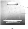
- the supporting structure further comprises a frame 6 ( Fig. 2 ) retaining the feed 2 positioner 3.
- the antenna reflector can have a modified shape and can be fixedly mounted in a different manner, e.g., by hanging or mounting on a support.
- Paraboloid reflectors particularly differ in the ratio of focal length to aperture diameter (f/D).
- Long-focus antennae are antennae having an f/D ratio greater than 0.5, whereas short-focus antennae have an f/D ratio less than 0.3.
- focal length is associated with reflector depth, i.e., the smaller the focal length, the deeper the reflector. Reflector depth has a significant effect on electrical parameters of the antenna. Smaller reflectors are fed more uniformly compared to deep reflectors, which contributes to a higher amplification coefficient.
- the positioner 3 comprising a primary rotation axis 7 and an auxiliary rotation axis 8, wherein the primary rotation axis 7 of the feed 2 positioner 3 passes through the center of the antenna reflector 1 and is perpendicular to the focal plane of the antenna reflector 1, whereas the auxiliary rotation axis 8 of the feed 2 positioner 3 is parallel to the primary rotation axis 7.
- the feed 2 positioner 3 comprising an equal-arm structure 9, each arm thereof arranged in a plane perpendicular to the primary 7 and auxiliary 8 rotation axes.
- the first arm 11 is connected at one end to the primary rotation axis 7 and adapted to be rotated around the primary axis 7, the feed 2 is connected to an end of the second arm 12, wherein the first arm 11 and the second arm 12 are adapted to be rotated with respect to each other at the point of connection between said arms, said point being located at the auxiliary rotation axis 8.
- the diameter of the antenna reflector 1 is at least 1.5 m, and the focal length of the antenna reflector 1 is at least 1.0 m.
- the focal plane of a wide-aperture long-focus reflector is generally parallel to the antenna plane. Due to the fact that the primary rotation axis 7 of the feed 2 positioner 3 passes through the center of the antenna reflector 1 and is perpendicular to the focal plane 4 of the antenna reflector 1, and the auxiliary rotation axis 8 is parallel to the primary rotation axis 7, and due to the fact that the arms 11, 12 of the positioner 3 are disposed in a plane perpendicular to the primary and auxiliary rotation axes 7, 8, the positioner 3 is capable of moving the feed 2 in the focal plane 4..
- the offered arrangement of the primary and auxiliary rotation axes 7,8 and of the equal-arm structure wherein the first arm 11 is connected at one end to the primary rotation axis 7 and adapted to be rotated around the primary axis 7, the feed 2 is connected to an end of the second arm 12, wherein the first arm 11 and the second arm 12 are adapted to be rotated with respect to each other at the point of connection between said arms, said point being located at the auxiliary rotation axis 8, provides the arrangement wherein the feed 2 can be located both at the focal point and at any point of the focal plane 4.
- such arrangement allows using the entire plane of the antenna reflector, excluding possibility of appearance of dead zones, which provides high quality of information received from space by the long-focus antenna.
- the optimal dimensions for the antenna are as follows: the diameter of the antenna reflector of at least 1.5 m, and the focal length of the antenna reflector of at least 1.0 m. Such dimensions are aimed at achieving lowest possible antenna reflector feed loss and allow receiving high-speed information data streams from low Earth orbit satellites. Furthermore, the disclosed antenna dimensions provide a lightweight and easily transported device.
- the feed is moved by means of the control device (not shown) configured to send control signals to the feed positioner 3.
- the control device allows directing the feed 2 precisely to the required position in the focal plane 4, and further allows tracking the maximum possible satellite trajectory section by moving the feed 2.
- the ability for standalone feed 2 operation simplifies antenna maintenance by not requiring on-site visits by a specialist.
- the proposed antenna is further easy to manufacture due to the antenna reflector installed in a fixed position (stationary relative to the Earth surface), i.e. there is no mechanism in the antenna for positioning the antenna reflector, which excludes a large number of components, which further simplifies the structure and provides more convenient antenna transportation. Furthermore, the antenna is easy to mount on any surface.
- the preferred orientation of the antenna reflector 1 is fixedly mounted in a horizontal plane 10 with respect to Earth surface.
- the offered arrangement of the antenna reflector 1 simplifies the installation process and contributes to structure security and durability due to uniform distribution of forces affecting the structure.
- the horizontal position of the antenna reflector 1 allows to scale (e.g., scale up) the diameter thereof without a significant weight increase of the antenna fastening assembly and without an increase in expenditures for components.
- the disclosed solution is aimed at providing maximum efficiency in reflector surface use.
- auxiliary rotation axis 8 of the feed positioner is the positioning of the auxiliary rotation axis 8 of the feed positioner within the antenna reflector 1.
- the positioner 3 arms 11, 12 engaged with each other at a point located at the auxiliary rotation axis 8 provide the feed 2 with access to any required point on the focal plane.
- Positioning the auxiliary rotation axis 8 outside the antenna reflector 1 is impractical.
- positioning said axis within the antenna reflector 1 leads to a decrease in metal consumption in the equal-arm structure 9 of the positioner 3, and therefore, to weight reduction of the structure.
- the feed can perform linear and/or curvilinear movement thereof.
- the positioner structure allows moving the feed 2 to any point on the focal plane 4.
- the curvilinear movement of the feed 2 facilitates achieving the optimal trajectory thereof.
- a radio transparent cover 13 mounted above the antenna reflector 1 and the feed 2 positioner 3 is used in some embodiments. Furthermore, the radio transparent cover 13 can be a part of the supporting structure of the feed positioner. In the preferred embodiment, the cover is made of a plastic or Plexiglas which provide the least data loss in the X band.
- the most suitable frequency band providing data reception from low Earth orbit satellites is the X band. Further, small-size antennae operating in the above range are easy to manufacture, which facilitates transportation, thus simplifying antenna usage.
- control device is configured to control the feed positioner based on predetermined control modes.
- the feed movement trajectory in the focal plane can be defined beforehand if time interval and movement trajectory of a satellite located within the antenna reception area are known. Therefore, the feed positioner based on predetermined control modes provides an automated structure.
- Data reception from low Earth orbit satellites by means of the antenna can be carried out as follows.
- the antenna is transported to the installation area and the antenna reflector 1 is positioned in a manner providing capture required satellite trajectory.
- the antenna frame 6 is then mounted, and the positioning mechanism 3 and the feed 2 are mounted thereon.
- a signal regarding the approaching satellite is received by the control device (not shown); control signals are then sent from the control device to the feed 2 positioner 3.
- the feed 2 is moved by means of the positioner 3 with respect to the antenna reflector 1 in accordance with control signals.
- the feed 2 is moved during at least one time interval, during which the first arm 11 and/or the second arm 12 is (are) rotated in order to provide linear and/or curvilinear feed movement.
- the disclosed method for receiving data by an antenna provides a technical result of an increase in coverage area during scanning using the antenna, while further providing high satellite data reception accuracy.
- control signals provide feed movement by means of the positioner based on predetermined control modes. For example, in this case the feed is moved at set times by rotating the first arm and the second arm simultaneously or sequentially in any required manner in order to position the feed as required.
- antennae for receiving data from low Earth orbit satellites should comprise long-focus reflectors with the f/D ratio equal or greater than 0.6.
- Such configuration allows utilizing only parallel feed movement in the focal plane of the reflector to control beam scanning, thus providing maximum simplification of the kinematic diagram.
- the above parameters are best met by an antenna reflector with the diameter of 2 m and the focal length of 1.4 m; further, X-band wavelength feed rotation area radius is up to 0.5 m.
- Such antenna parameters allow tracking low Earth orbit satellites (about 600-650 km above the Earth surface) during a short zenithal trajectory section (about 30 seconds corresponding to 200 km of trajectory distance) in order to receive high-speed (up to 500 Mbit/s) Earth surface information data streams from space, providing images of the Earth surface with spatial resolution of 1 meter and higher.
- the antenna services a local area with a radius of 100-150 km from the installation point. This antenna configuration provides optimal data reception parameters while retaining compact dimensions of the antenna.
- the present invention can be used in various applications, including emergency situations, educational programs, ecological monitoring, local (regional) weather forecast, forestry, agriculture, infrastructure monitoring (monitoring buildings, roads, oil and gas pipelines, etc.), logistics services, etc.
- FIG. 3 shows an image received by the antenna for receiving data of the present invention from the Terra satellite on December 7th, 2016 in Moscow.
- the offered antenna structure allows receiving signals from the widest possible satellite trajectory section by using a long-focus antenna reflector and a feed moveable with respect to the reflector.
- the offered positioner structure provides stable and steady feed movement in focal plane, allowing to receive high-speed Earth observation data streams of high spatial resolution from low Earth orbit satellites.
- the offered antenna meets all structural security and durability requirements, is technologically simple and easy to install.
Landscapes
- Aerials With Secondary Devices (AREA)
- Variable-Direction Aerials And Aerial Arrays (AREA)
- Radio Relay Systems (AREA)
- Support Of Aerials (AREA)
Applications Claiming Priority (1)
| Application Number | Priority Date | Filing Date | Title |
|---|---|---|---|
| PCT/RU2017/000627 WO2019045585A1 (en) | 2017-08-29 | 2017-08-29 | ANTENNA FOR RECEIVING SATELLITE DATA IN LOW ORBIT |
Publications (2)
| Publication Number | Publication Date |
|---|---|
| EP3676909A1 EP3676909A1 (en) | 2020-07-08 |
| EP3676909B1 true EP3676909B1 (en) | 2022-03-16 |
Family
ID=61768378
Family Applications (1)
| Application Number | Title | Priority Date | Filing Date |
|---|---|---|---|
| EP17854229.6A Active EP3676909B1 (en) | 2017-08-29 | 2017-08-29 | Antenna for receiving data from low earth orbit satellites |
Country Status (8)
| Country | Link |
|---|---|
| US (1) | US11398675B2 (es) |
| EP (1) | EP3676909B1 (es) |
| JP (1) | JP6865897B2 (es) |
| CN (1) | CN111226352B (es) |
| EA (1) | EA032674B1 (es) |
| ES (1) | ES2918512T3 (es) |
| IL (1) | IL272961B2 (es) |
| WO (1) | WO2019045585A1 (es) |
Families Citing this family (3)
| Publication number | Priority date | Publication date | Assignee | Title |
|---|---|---|---|---|
| RU205102U1 (ru) * | 2020-06-22 | 2021-06-28 | Общество с ограниченной ответственностью "Лоретт" | Антенная станция приема сигналов исз повышенной жесткости |
| US20220158342A1 (en) * | 2020-11-16 | 2022-05-19 | Boise State University | Reconfigurable antenna |
| WO2024097277A1 (en) * | 2022-11-01 | 2024-05-10 | Viasat, Inc. | Techniques for peaking reflector antennas |
Family Cites Families (15)
| Publication number | Priority date | Publication date | Assignee | Title |
|---|---|---|---|---|
| BE551006A (es) * | 1955-10-03 | |||
| US3407404A (en) * | 1964-10-05 | 1968-10-22 | Bell Telephone Labor Inc | Directive microwave antenna capable of rotating about two intersecting axes |
| US3848255A (en) * | 1973-03-22 | 1974-11-12 | Teledyne Inc | Steerable radar antenna |
| US4010472A (en) * | 1975-11-14 | 1977-03-01 | Westinghouse Electric Corporation | Antenna scanning apparatus |
| US4298877A (en) * | 1979-01-26 | 1981-11-03 | Solar Energy Technology, Inc. | Offset-fed multi-beam tracking antenna system utilizing especially shaped reflector surfaces |
| WO1996002953A1 (en) | 1994-07-20 | 1996-02-01 | Commonwealth Scientific And Industrial Research Organisation | Feed movement mechanism and control system for a multibeam antenna |
| JPH09121118A (ja) | 1995-07-21 | 1997-05-06 | Daewoo Electron Co Ltd | パラボラアンテナ |
| JP2002516502A (ja) | 1998-05-20 | 2002-06-04 | エル−スリー・コミュニケーションズ・エスコ・インコーポレーテッド | マルチビーム衛星通信アンテナ |
| JP4198867B2 (ja) * | 2000-06-23 | 2008-12-17 | 株式会社東芝 | アンテナ装置 |
| EP1641076A1 (en) * | 2001-09-28 | 2006-03-29 | Sumitomo Electric Industries, Ltd. | Radio wave lens antenna device |
| CN100421299C (zh) * | 2005-09-29 | 2008-09-24 | 西安电子科技大学 | 柔性结构天线馈源精确定位定姿技术 |
| CN201838708U (zh) | 2010-07-12 | 2011-05-18 | 四川湖山电器有限责任公司 | 快速架设和收拢的便携式抛物面卫星接收天线 |
| US10158170B2 (en) * | 2016-01-25 | 2018-12-18 | International Business Machines Corporation | Two-dimensional scanning cylindrical reflector |
| EP3229313B1 (en) * | 2016-04-06 | 2019-03-20 | MacDonald, Dettwiler and Associates Corporation | Three axis reflector deployment and pointing mechanism |
| CN106785444A (zh) * | 2016-12-29 | 2017-05-31 | 中国电子科技集团公司第五十四研究所 | 一种双旋臂式龙伯透镜天线 |
-
2017
- 2017-08-29 WO PCT/RU2017/000627 patent/WO2019045585A1/en active Application Filing
- 2017-08-29 JP JP2020534157A patent/JP6865897B2/ja active Active
- 2017-08-29 IL IL272961A patent/IL272961B2/en unknown
- 2017-08-29 EP EP17854229.6A patent/EP3676909B1/en active Active
- 2017-08-29 US US16/644,728 patent/US11398675B2/en active Active
- 2017-08-29 EA EA201892177A patent/EA032674B1/ru unknown
- 2017-08-29 ES ES17854229T patent/ES2918512T3/es active Active
- 2017-08-29 CN CN201780095873.7A patent/CN111226352B/zh active Active
Also Published As
| Publication number | Publication date |
|---|---|
| IL272961B2 (en) | 2023-03-01 |
| CN111226352B (zh) | 2021-05-11 |
| ES2918512T3 (es) | 2022-07-18 |
| EA201892177A1 (ru) | 2019-03-29 |
| EP3676909A1 (en) | 2020-07-08 |
| WO2019045585A1 (en) | 2019-03-07 |
| US20220115779A1 (en) | 2022-04-14 |
| JP6865897B2 (ja) | 2021-04-28 |
| EA032674B1 (ru) | 2019-06-28 |
| JP2020532931A (ja) | 2020-11-12 |
| IL272961A (en) | 2020-04-30 |
| IL272961B (en) | 2022-11-01 |
| CN111226352A (zh) | 2020-06-02 |
| US11398675B2 (en) | 2022-07-26 |
Similar Documents
| Publication | Publication Date | Title |
|---|---|---|
| EP3676909B1 (en) | Antenna for receiving data from low earth orbit satellites | |
| US6204822B1 (en) | Multibeam satellite communication antenna | |
| US6950061B2 (en) | Antenna array for moving vehicles | |
| US7453409B2 (en) | Low profile antenna system and associated methods | |
| US8743001B2 (en) | Mechanically steered reflector antenna | |
| Densmore et al. | A satellite-tracking K-and K/sub a/-band mobile vehicle antenna system | |
| US7411561B1 (en) | Gimbaled dragonian antenna | |
| US9337536B1 (en) | Electronically steerable SATCOM antenna | |
| US6747604B2 (en) | Steerable offset antenna with fixed feed source | |
| CN1964137B (zh) | 平板式卫星自动跟踪天线系统 | |
| TW405279B (en) | Antenna for communicating with low earth orbit satellite | |
| WO2010080545A2 (en) | Subreflector tracking method, apparatus and system for reflector antenna | |
| US5945960A (en) | Method and apparatus for reconfiguring antenna radiation patterns | |
| US7450079B1 (en) | Gimbaled gregorian antenna | |
| US20210005963A1 (en) | Antenna apparatus | |
| JP2001144529A (ja) | 非静止衛星へのアンテナビーム指向方法 | |
| Nan et al. | Kilometer-square Area Radio Synthesis Telescope KARST | |
| Poperetchenko | Antenna Systems for Space Communication, Radio Astronomy and SETI | |
| Montebugnoli et al. | A potential integrated multiwavelength radar system at the medicina radiotelescopes | |
| Possenti | The SRT & (br) other single-dish telescopes | |
| Zhu et al. | Demonstrator Review for KARST | |
| AU7242700A (en) | Multibeam satellite communication antenna | |
| JPH06152223A (ja) | Csアンテナ | |
| IL201137A (en) | Low profile satellite communications antenna | |
| JP2002111373A (ja) | 副反射鏡オフセットパラボラアンテナ |
Legal Events
| Date | Code | Title | Description |
|---|---|---|---|
| STAA | Information on the status of an ep patent application or granted ep patent |
Free format text: STATUS: UNKNOWN |
|
| STAA | Information on the status of an ep patent application or granted ep patent |
Free format text: STATUS: THE INTERNATIONAL PUBLICATION HAS BEEN MADE |
|
| PUAI | Public reference made under article 153(3) epc to a published international application that has entered the european phase |
Free format text: ORIGINAL CODE: 0009012 |
|
| STAA | Information on the status of an ep patent application or granted ep patent |
Free format text: STATUS: REQUEST FOR EXAMINATION WAS MADE |
|
| 17P | Request for examination filed |
Effective date: 20200305 |
|
| AK | Designated contracting states |
Kind code of ref document: A1 Designated state(s): AL AT BE BG CH CY CZ DE DK EE ES FI FR GB GR HR HU IE IS IT LI LT LU LV MC MK MT NL NO PL PT RO RS SE SI SK SM TR |
|
| AX | Request for extension of the european patent |
Extension state: BA ME |
|
| DAV | Request for validation of the european patent (deleted) | ||
| DAX | Request for extension of the european patent (deleted) | ||
| STAA | Information on the status of an ep patent application or granted ep patent |
Free format text: STATUS: EXAMINATION IS IN PROGRESS |
|
| 17Q | First examination report despatched |
Effective date: 20210219 |
|
| GRAP | Despatch of communication of intention to grant a patent |
Free format text: ORIGINAL CODE: EPIDOSNIGR1 |
|
| STAA | Information on the status of an ep patent application or granted ep patent |
Free format text: STATUS: GRANT OF PATENT IS INTENDED |
|
| GRAJ | Information related to disapproval of communication of intention to grant by the applicant or resumption of examination proceedings by the epo deleted |
Free format text: ORIGINAL CODE: EPIDOSDIGR1 |
|
| GRAP | Despatch of communication of intention to grant a patent |
Free format text: ORIGINAL CODE: EPIDOSNIGR1 |
|
| STAA | Information on the status of an ep patent application or granted ep patent |
Free format text: STATUS: GRANT OF PATENT IS INTENDED |
|
| INTG | Intention to grant announced |
Effective date: 20211011 |
|
| INTG | Intention to grant announced |
Effective date: 20211103 |
|
| GRAS | Grant fee paid |
Free format text: ORIGINAL CODE: EPIDOSNIGR3 |
|
| GRAA | (expected) grant |
Free format text: ORIGINAL CODE: 0009210 |
|
| STAA | Information on the status of an ep patent application or granted ep patent |
Free format text: STATUS: THE PATENT HAS BEEN GRANTED |
|
| AK | Designated contracting states |
Kind code of ref document: B1 Designated state(s): AL AT BE BG CH CY CZ DE DK EE ES FI FR GB GR HR HU IE IS IT LI LT LU LV MC MK MT NL NO PL PT RO RS SE SI SK SM TR |
|
| REG | Reference to a national code |
Ref country code: GB Ref legal event code: FG4D |
|
| REG | Reference to a national code |
Ref country code: CH Ref legal event code: EP |
|
| REG | Reference to a national code |
Ref country code: DE Ref legal event code: R096 Ref document number: 602017054775 Country of ref document: DE |
|
| REG | Reference to a national code |
Ref country code: IE Ref legal event code: FG4D |
|
| REG | Reference to a national code |
Ref country code: AT Ref legal event code: REF Ref document number: 1476541 Country of ref document: AT Kind code of ref document: T Effective date: 20220415 |
|
| REG | Reference to a national code |
Ref country code: LT Ref legal event code: MG9D |
|
| REG | Reference to a national code |
Ref country code: ES Ref legal event code: FG2A Ref document number: 2918512 Country of ref document: ES Kind code of ref document: T3 Effective date: 20220718 |
|
| REG | Reference to a national code |
Ref country code: NL Ref legal event code: MP Effective date: 20220316 |
|
| PG25 | Lapsed in a contracting state [announced via postgrant information from national office to epo] |
Ref country code: SE Free format text: LAPSE BECAUSE OF FAILURE TO SUBMIT A TRANSLATION OF THE DESCRIPTION OR TO PAY THE FEE WITHIN THE PRESCRIBED TIME-LIMIT Effective date: 20220316 Ref country code: RS Free format text: LAPSE BECAUSE OF FAILURE TO SUBMIT A TRANSLATION OF THE DESCRIPTION OR TO PAY THE FEE WITHIN THE PRESCRIBED TIME-LIMIT Effective date: 20220316 Ref country code: NO Free format text: LAPSE BECAUSE OF FAILURE TO SUBMIT A TRANSLATION OF THE DESCRIPTION OR TO PAY THE FEE WITHIN THE PRESCRIBED TIME-LIMIT Effective date: 20220616 Ref country code: LT Free format text: LAPSE BECAUSE OF FAILURE TO SUBMIT A TRANSLATION OF THE DESCRIPTION OR TO PAY THE FEE WITHIN THE PRESCRIBED TIME-LIMIT Effective date: 20220316 Ref country code: HR Free format text: LAPSE BECAUSE OF FAILURE TO SUBMIT A TRANSLATION OF THE DESCRIPTION OR TO PAY THE FEE WITHIN THE PRESCRIBED TIME-LIMIT Effective date: 20220316 Ref country code: BG Free format text: LAPSE BECAUSE OF FAILURE TO SUBMIT A TRANSLATION OF THE DESCRIPTION OR TO PAY THE FEE WITHIN THE PRESCRIBED TIME-LIMIT Effective date: 20220616 |
|
| REG | Reference to a national code |
Ref country code: AT Ref legal event code: MK05 Ref document number: 1476541 Country of ref document: AT Kind code of ref document: T Effective date: 20220316 |
|
| PG25 | Lapsed in a contracting state [announced via postgrant information from national office to epo] |
Ref country code: LV Free format text: LAPSE BECAUSE OF FAILURE TO SUBMIT A TRANSLATION OF THE DESCRIPTION OR TO PAY THE FEE WITHIN THE PRESCRIBED TIME-LIMIT Effective date: 20220316 Ref country code: GR Free format text: LAPSE BECAUSE OF FAILURE TO SUBMIT A TRANSLATION OF THE DESCRIPTION OR TO PAY THE FEE WITHIN THE PRESCRIBED TIME-LIMIT Effective date: 20220617 Ref country code: FI Free format text: LAPSE BECAUSE OF FAILURE TO SUBMIT A TRANSLATION OF THE DESCRIPTION OR TO PAY THE FEE WITHIN THE PRESCRIBED TIME-LIMIT Effective date: 20220316 |
|
| PG25 | Lapsed in a contracting state [announced via postgrant information from national office to epo] |
Ref country code: NL Free format text: LAPSE BECAUSE OF FAILURE TO SUBMIT A TRANSLATION OF THE DESCRIPTION OR TO PAY THE FEE WITHIN THE PRESCRIBED TIME-LIMIT Effective date: 20220316 |
|
| PG25 | Lapsed in a contracting state [announced via postgrant information from national office to epo] |
Ref country code: SM Free format text: LAPSE BECAUSE OF FAILURE TO SUBMIT A TRANSLATION OF THE DESCRIPTION OR TO PAY THE FEE WITHIN THE PRESCRIBED TIME-LIMIT Effective date: 20220316 Ref country code: SK Free format text: LAPSE BECAUSE OF FAILURE TO SUBMIT A TRANSLATION OF THE DESCRIPTION OR TO PAY THE FEE WITHIN THE PRESCRIBED TIME-LIMIT Effective date: 20220316 Ref country code: RO Free format text: LAPSE BECAUSE OF FAILURE TO SUBMIT A TRANSLATION OF THE DESCRIPTION OR TO PAY THE FEE WITHIN THE PRESCRIBED TIME-LIMIT Effective date: 20220316 Ref country code: PT Free format text: LAPSE BECAUSE OF FAILURE TO SUBMIT A TRANSLATION OF THE DESCRIPTION OR TO PAY THE FEE WITHIN THE PRESCRIBED TIME-LIMIT Effective date: 20220718 Ref country code: EE Free format text: LAPSE BECAUSE OF FAILURE TO SUBMIT A TRANSLATION OF THE DESCRIPTION OR TO PAY THE FEE WITHIN THE PRESCRIBED TIME-LIMIT Effective date: 20220316 Ref country code: CZ Free format text: LAPSE BECAUSE OF FAILURE TO SUBMIT A TRANSLATION OF THE DESCRIPTION OR TO PAY THE FEE WITHIN THE PRESCRIBED TIME-LIMIT Effective date: 20220316 Ref country code: AT Free format text: LAPSE BECAUSE OF FAILURE TO SUBMIT A TRANSLATION OF THE DESCRIPTION OR TO PAY THE FEE WITHIN THE PRESCRIBED TIME-LIMIT Effective date: 20220316 |
|
| PG25 | Lapsed in a contracting state [announced via postgrant information from national office to epo] |
Ref country code: PL Free format text: LAPSE BECAUSE OF FAILURE TO SUBMIT A TRANSLATION OF THE DESCRIPTION OR TO PAY THE FEE WITHIN THE PRESCRIBED TIME-LIMIT Effective date: 20220316 Ref country code: IS Free format text: LAPSE BECAUSE OF FAILURE TO SUBMIT A TRANSLATION OF THE DESCRIPTION OR TO PAY THE FEE WITHIN THE PRESCRIBED TIME-LIMIT Effective date: 20220716 Ref country code: AL Free format text: LAPSE BECAUSE OF FAILURE TO SUBMIT A TRANSLATION OF THE DESCRIPTION OR TO PAY THE FEE WITHIN THE PRESCRIBED TIME-LIMIT Effective date: 20220316 |
|
| REG | Reference to a national code |
Ref country code: DE Ref legal event code: R097 Ref document number: 602017054775 Country of ref document: DE |
|
| PLBE | No opposition filed within time limit |
Free format text: ORIGINAL CODE: 0009261 |
|
| STAA | Information on the status of an ep patent application or granted ep patent |
Free format text: STATUS: NO OPPOSITION FILED WITHIN TIME LIMIT |
|
| PG25 | Lapsed in a contracting state [announced via postgrant information from national office to epo] |
Ref country code: DK Free format text: LAPSE BECAUSE OF FAILURE TO SUBMIT A TRANSLATION OF THE DESCRIPTION OR TO PAY THE FEE WITHIN THE PRESCRIBED TIME-LIMIT Effective date: 20220316 |
|
| 26N | No opposition filed |
Effective date: 20221219 |
|
| PG25 | Lapsed in a contracting state [announced via postgrant information from national office to epo] |
Ref country code: SI Free format text: LAPSE BECAUSE OF FAILURE TO SUBMIT A TRANSLATION OF THE DESCRIPTION OR TO PAY THE FEE WITHIN THE PRESCRIBED TIME-LIMIT Effective date: 20220316 |
|
| PG25 | Lapsed in a contracting state [announced via postgrant information from national office to epo] |
Ref country code: MC Free format text: LAPSE BECAUSE OF FAILURE TO SUBMIT A TRANSLATION OF THE DESCRIPTION OR TO PAY THE FEE WITHIN THE PRESCRIBED TIME-LIMIT Effective date: 20220316 |
|
| REG | Reference to a national code |
Ref country code: CH Ref legal event code: PL |
|
| PG25 | Lapsed in a contracting state [announced via postgrant information from national office to epo] |
Ref country code: LU Free format text: LAPSE BECAUSE OF NON-PAYMENT OF DUE FEES Effective date: 20220829 Ref country code: LI Free format text: LAPSE BECAUSE OF NON-PAYMENT OF DUE FEES Effective date: 20220831 Ref country code: CH Free format text: LAPSE BECAUSE OF NON-PAYMENT OF DUE FEES Effective date: 20220831 |
|
| REG | Reference to a national code |
Ref country code: BE Ref legal event code: MM Effective date: 20220831 |
|
| PG25 | Lapsed in a contracting state [announced via postgrant information from national office to epo] |
Ref country code: IE Free format text: LAPSE BECAUSE OF NON-PAYMENT OF DUE FEES Effective date: 20220829 |
|
| PG25 | Lapsed in a contracting state [announced via postgrant information from national office to epo] |
Ref country code: BE Free format text: LAPSE BECAUSE OF NON-PAYMENT OF DUE FEES Effective date: 20220831 |
|
| PGFP | Annual fee paid to national office [announced via postgrant information from national office to epo] |
Ref country code: TR Payment date: 20230825 Year of fee payment: 7 Ref country code: IT Payment date: 20230831 Year of fee payment: 7 Ref country code: GB Payment date: 20230829 Year of fee payment: 7 Ref country code: ES Payment date: 20230904 Year of fee payment: 7 |
|
| PGFP | Annual fee paid to national office [announced via postgrant information from national office to epo] |
Ref country code: FR Payment date: 20230825 Year of fee payment: 7 Ref country code: DE Payment date: 20230829 Year of fee payment: 7 |
|
| P01 | Opt-out of the competence of the unified patent court (upc) registered |
Effective date: 20240112 |
|
| PG25 | Lapsed in a contracting state [announced via postgrant information from national office to epo] |
Ref country code: CY Free format text: LAPSE BECAUSE OF FAILURE TO SUBMIT A TRANSLATION OF THE DESCRIPTION OR TO PAY THE FEE WITHIN THE PRESCRIBED TIME-LIMIT Effective date: 20220316 |