EP3676890B1 - Energiespeichersystem - Google Patents
Energiespeichersystem Download PDFInfo
- Publication number
- EP3676890B1 EP3676890B1 EP18758545.0A EP18758545A EP3676890B1 EP 3676890 B1 EP3676890 B1 EP 3676890B1 EP 18758545 A EP18758545 A EP 18758545A EP 3676890 B1 EP3676890 B1 EP 3676890B1
- Authority
- EP
- European Patent Office
- Prior art keywords
- energy storage
- cells
- storage system
- storage
- energy
- Prior art date
- Legal status (The legal status is an assumption and is not a legal conclusion. Google has not performed a legal analysis and makes no representation as to the accuracy of the status listed.)
- Active
Links
Images




Classifications
-
- H—ELECTRICITY
- H01—ELECTRIC ELEMENTS
- H01M—PROCESSES OR MEANS, e.g. BATTERIES, FOR THE DIRECT CONVERSION OF CHEMICAL ENERGY INTO ELECTRICAL ENERGY
- H01M10/00—Secondary cells; Manufacture thereof
- H01M10/60—Heating or cooling; Temperature control
- H01M10/65—Means for temperature control structurally associated with the cells
- H01M10/653—Means for temperature control structurally associated with the cells characterised by electrically insulating or thermally conductive materials
-
- H—ELECTRICITY
- H01—ELECTRIC ELEMENTS
- H01M—PROCESSES OR MEANS, e.g. BATTERIES, FOR THE DIRECT CONVERSION OF CHEMICAL ENERGY INTO ELECTRICAL ENERGY
- H01M10/00—Secondary cells; Manufacture thereof
- H01M10/60—Heating or cooling; Temperature control
- H01M10/61—Types of temperature control
- H01M10/613—Cooling or keeping cold
-
- H—ELECTRICITY
- H01—ELECTRIC ELEMENTS
- H01M—PROCESSES OR MEANS, e.g. BATTERIES, FOR THE DIRECT CONVERSION OF CHEMICAL ENERGY INTO ELECTRICAL ENERGY
- H01M10/00—Secondary cells; Manufacture thereof
- H01M10/60—Heating or cooling; Temperature control
- H01M10/64—Heating or cooling; Temperature control characterised by the shape of the cells
- H01M10/647—Prismatic or flat cells, e.g. pouch cells
-
- H—ELECTRICITY
- H01—ELECTRIC ELEMENTS
- H01M—PROCESSES OR MEANS, e.g. BATTERIES, FOR THE DIRECT CONVERSION OF CHEMICAL ENERGY INTO ELECTRICAL ENERGY
- H01M10/00—Secondary cells; Manufacture thereof
- H01M10/60—Heating or cooling; Temperature control
- H01M10/65—Means for temperature control structurally associated with the cells
- H01M10/655—Solid structures for heat exchange or heat conduction
- H01M10/6554—Rods or plates
- H01M10/6555—Rods or plates arranged between the cells
-
- H—ELECTRICITY
- H01—ELECTRIC ELEMENTS
- H01M—PROCESSES OR MEANS, e.g. BATTERIES, FOR THE DIRECT CONVERSION OF CHEMICAL ENERGY INTO ELECTRICAL ENERGY
- H01M10/00—Secondary cells; Manufacture thereof
- H01M10/60—Heating or cooling; Temperature control
- H01M10/65—Means for temperature control structurally associated with the cells
- H01M10/658—Means for temperature control structurally associated with the cells by thermal insulation or shielding
-
- H—ELECTRICITY
- H01—ELECTRIC ELEMENTS
- H01M—PROCESSES OR MEANS, e.g. BATTERIES, FOR THE DIRECT CONVERSION OF CHEMICAL ENERGY INTO ELECTRICAL ENERGY
- H01M10/00—Secondary cells; Manufacture thereof
- H01M10/60—Heating or cooling; Temperature control
- H01M10/65—Means for temperature control structurally associated with the cells
- H01M10/659—Means for temperature control structurally associated with the cells by heat storage or buffering, e.g. heat capacity or liquid-solid phase changes or transition
-
- H—ELECTRICITY
- H01—ELECTRIC ELEMENTS
- H01M—PROCESSES OR MEANS, e.g. BATTERIES, FOR THE DIRECT CONVERSION OF CHEMICAL ENERGY INTO ELECTRICAL ENERGY
- H01M50/00—Constructional details or processes of manufacture of the non-active parts of electrochemical cells other than fuel cells, e.g. hybrid cells
- H01M50/20—Mountings; Secondary casings or frames; Racks, modules or packs; Suspension devices; Shock absorbers; Transport or carrying devices; Holders
-
- H—ELECTRICITY
- H01—ELECTRIC ELEMENTS
- H01M—PROCESSES OR MEANS, e.g. BATTERIES, FOR THE DIRECT CONVERSION OF CHEMICAL ENERGY INTO ELECTRICAL ENERGY
- H01M50/00—Constructional details or processes of manufacture of the non-active parts of electrochemical cells other than fuel cells, e.g. hybrid cells
- H01M50/20—Mountings; Secondary casings or frames; Racks, modules or packs; Suspension devices; Shock absorbers; Transport or carrying devices; Holders
- H01M50/204—Racks, modules or packs for multiple batteries or multiple cells
- H01M50/207—Racks, modules or packs for multiple batteries or multiple cells characterised by their shape
- H01M50/209—Racks, modules or packs for multiple batteries or multiple cells characterised by their shape adapted for prismatic or rectangular cells
-
- H—ELECTRICITY
- H01—ELECTRIC ELEMENTS
- H01M—PROCESSES OR MEANS, e.g. BATTERIES, FOR THE DIRECT CONVERSION OF CHEMICAL ENERGY INTO ELECTRICAL ENERGY
- H01M50/00—Constructional details or processes of manufacture of the non-active parts of electrochemical cells other than fuel cells, e.g. hybrid cells
- H01M50/20—Mountings; Secondary casings or frames; Racks, modules or packs; Suspension devices; Shock absorbers; Transport or carrying devices; Holders
- H01M50/204—Racks, modules or packs for multiple batteries or multiple cells
- H01M50/207—Racks, modules or packs for multiple batteries or multiple cells characterised by their shape
- H01M50/211—Racks, modules or packs for multiple batteries or multiple cells characterised by their shape adapted for pouch cells
-
- H—ELECTRICITY
- H01—ELECTRIC ELEMENTS
- H01M—PROCESSES OR MEANS, e.g. BATTERIES, FOR THE DIRECT CONVERSION OF CHEMICAL ENERGY INTO ELECTRICAL ENERGY
- H01M50/00—Constructional details or processes of manufacture of the non-active parts of electrochemical cells other than fuel cells, e.g. hybrid cells
- H01M50/20—Mountings; Secondary casings or frames; Racks, modules or packs; Suspension devices; Shock absorbers; Transport or carrying devices; Holders
- H01M50/218—Mountings; Secondary casings or frames; Racks, modules or packs; Suspension devices; Shock absorbers; Transport or carrying devices; Holders characterised by the material
- H01M50/22—Mountings; Secondary casings or frames; Racks, modules or packs; Suspension devices; Shock absorbers; Transport or carrying devices; Holders characterised by the material of the casings or racks
- H01M50/222—Inorganic material
-
- H—ELECTRICITY
- H01—ELECTRIC ELEMENTS
- H01M—PROCESSES OR MEANS, e.g. BATTERIES, FOR THE DIRECT CONVERSION OF CHEMICAL ENERGY INTO ELECTRICAL ENERGY
- H01M50/00—Constructional details or processes of manufacture of the non-active parts of electrochemical cells other than fuel cells, e.g. hybrid cells
- H01M50/20—Mountings; Secondary casings or frames; Racks, modules or packs; Suspension devices; Shock absorbers; Transport or carrying devices; Holders
- H01M50/289—Mountings; Secondary casings or frames; Racks, modules or packs; Suspension devices; Shock absorbers; Transport or carrying devices; Holders characterised by spacing elements or positioning means within frames, racks or packs
- H01M50/291—Mountings; Secondary casings or frames; Racks, modules or packs; Suspension devices; Shock absorbers; Transport or carrying devices; Holders characterised by spacing elements or positioning means within frames, racks or packs characterised by their shape
-
- H—ELECTRICITY
- H01—ELECTRIC ELEMENTS
- H01M—PROCESSES OR MEANS, e.g. BATTERIES, FOR THE DIRECT CONVERSION OF CHEMICAL ENERGY INTO ELECTRICAL ENERGY
- H01M50/00—Constructional details or processes of manufacture of the non-active parts of electrochemical cells other than fuel cells, e.g. hybrid cells
- H01M50/20—Mountings; Secondary casings or frames; Racks, modules or packs; Suspension devices; Shock absorbers; Transport or carrying devices; Holders
- H01M50/289—Mountings; Secondary casings or frames; Racks, modules or packs; Suspension devices; Shock absorbers; Transport or carrying devices; Holders characterised by spacing elements or positioning means within frames, racks or packs
- H01M50/293—Mountings; Secondary casings or frames; Racks, modules or packs; Suspension devices; Shock absorbers; Transport or carrying devices; Holders characterised by spacing elements or positioning means within frames, racks or packs characterised by the material
-
- H—ELECTRICITY
- H01—ELECTRIC ELEMENTS
- H01M—PROCESSES OR MEANS, e.g. BATTERIES, FOR THE DIRECT CONVERSION OF CHEMICAL ENERGY INTO ELECTRICAL ENERGY
- H01M2220/00—Batteries for particular applications
- H01M2220/20—Batteries in motive systems, e.g. vehicle, ship, plane
-
- Y—GENERAL TAGGING OF NEW TECHNOLOGICAL DEVELOPMENTS; GENERAL TAGGING OF CROSS-SECTIONAL TECHNOLOGIES SPANNING OVER SEVERAL SECTIONS OF THE IPC; TECHNICAL SUBJECTS COVERED BY FORMER USPC CROSS-REFERENCE ART COLLECTIONS [XRACs] AND DIGESTS
- Y02—TECHNOLOGIES OR APPLICATIONS FOR MITIGATION OR ADAPTATION AGAINST CLIMATE CHANGE
- Y02E—REDUCTION OF GREENHOUSE GAS [GHG] EMISSIONS, RELATED TO ENERGY GENERATION, TRANSMISSION OR DISTRIBUTION
- Y02E60/00—Enabling technologies; Technologies with a potential or indirect contribution to GHG emissions mitigation
- Y02E60/10—Energy storage using batteries
Definitions
- the invention relates to an energy storage system comprising a housing in which a plurality of storage cells are arranged, the storage cells being thermally insulated from one another by means of a device arranged between the storage cells.
- Energy storage systems in particular rechargeable storage devices for electrical energy, are particularly widespread in mobile systems.
- Rechargeable storage devices for electrical energy are used, for example, in portable electronic devices such as smartphones or laptops.
- rechargeable storage devices for electrical energy are increasingly used to provide energy for electrically powered vehicles.
- Further areas of application for electrical energy storage systems are stationary applications, for example in backup systems, in network stabilization systems and for storing electrical energy from renewable energy sources.
- a frequently used energy storage system is a rechargeable storage device in the form of a lithium-ion battery.
- Lithium-ion accumulators like other rechargeable stores for electrical energy, usually have several storage cells, which are stored together in are built into a housing. Several electrically interconnected storage cells form a module.
- the energy storage system does not only extend to lithium-ion batteries.
- Other rechargeable battery systems such as lithium-sulfur batteries, solid-state batteries or metal-air batteries are also conceivable energy storage systems.
- supercapacitors can also be used as energy storage systems.
- Energy storage systems in the form of rechargeable storage devices have the highest electrical capacity only in a limited temperature range. If the optimum operating temperature range is exceeded or not reached, the electrical capacity of the storage unit drops sharply or the functionality of the energy storage unit is impaired.
- thermal runaway is known in particular in the case of lithium-ion cells.
- high amounts of thermal energy and gaseous decomposition products are released in a short time, resulting in high pressure and high temperatures in the housing.
- This effect is particularly problematic in the case of energy storage systems with a high energy density, such as is required, for example, to provide electrical energy for the provision of electrically driven vehicles.
- the problem of thermal runaway increases due to increasing amounts of energy from individual cells and an increase in the packing density of the cells arranged in the housing.
- temperatures in the range of 600 ° C. can arise over a period of about 30 seconds.
- the establishment For thermal insulation, it has to withstand such stress and reduce the energy transfer to neighboring cells in such a way that the temperature load on neighboring cells is only around 150 ° C. It is then necessary to replace the energy storage device or the defective cell. In this respect, it is admittedly permissible that the device changes irreversibly during this process. It is essential to limit the energy transfer to neighboring cells in order to prevent these cells from going through thermally.
- phase change material between the cells, see e.g. US 2011/159340 A1 and U.S. 5,578,393 A .
- the invention is based on the object of providing an energy storage system which has a high level of operational reliability.
- the energy storage system comprises a housing in which a plurality of storage cells are arranged, the storage cells being thermally insulated from one another by means of a device arranged between the storage cells, the device being designed such that the storage cells are spaced from one another, the device being made of a temperature-resistant material is trained.
- the cells can be prismatic cells or pouch cells.
- the invention also allows adaptation to storage systems with round cells.
- the storage cells are spaced apart from one another, a direct heat transfer from one storage cell to an adjacent one can take place Memory cell can be prevented.
- the heat transfer is further reduced by the device arranged between the storage cells.
- the device is preferably also designed to be elastic. As a result, the device can follow any dimensional changes in the storage cells and thus prevent an inadmissibly high pressure from building up inside the storage cells.
- the temperature-resistant configuration of the device can furthermore prevent the device from being destroyed even in the event of a thermal runaway of a memory cell, so that the thermal runaway can be prevented from spreading to neighboring memory cells.
- the elastic configuration can be realized by the choice of material and / or shape of the device.
- the device also has elevations and depressions. Such a structuring is obtained, for example, when the device is structured in a waffle-like manner. Furthermore, such a configuration results when the device has an undulating profile.
- materials are used in the device which are subject to an endothermic reaction when heated to over 200 ° C., for example through recrystallization or the release of crystal water. Such a design leads to an additional heat cushion and slows down the heat transfer between the cells.
- Such materials are, for example, inorganic salts such as nitrates or carbonates.
- Hydroxides or oxy-hydroxides which can split off water at elevated temperatures, are also conceivable. For example, when Mg (OH) 2 is split off at temperatures above about 350 ° C., amounts of energy of about 1,200 kJ / kg are typically absorbed. When water is split off from Al (OH) 3 , amounts of energy of around 1,100 kJ / kg are absorbed at temperatures above approx. 250 ° C.
- the device particularly preferably has a low thermal conductivity.
- the thermal conductivity of the device is preferably at most 0.1 W / mK. In this context, it is particularly relevant to minimize the heat transfer between the cells.
- the device can for example be formed from a material with low thermal conductivity.
- the device can have a shape which reduces the heat transfer. This can be done, for example, by reducing the contact area, labyrinth structures and the like.
- the device is preferably designed to be flat, so that the storage cells can be supported on the device along the main sides facing one another. This results in a mechanically stable arrangement of the storage cells. With this configuration, the assembly of the energy store is also simplified.
- the device can be structured three-dimensionally. As a result, zones of the device are formed which bear against the memory cells and zones which are spaced apart from the memory cells. Cavities are formed which improve the thermal insulation.
- the cavity cells can have a rectangular, polygonal or round cross section.
- the device has protruding webs. As a result, large-area zones are formed which are spaced apart from the storage cells. The contact area of the device to the memory cells is relatively small.
- the webs are subject to the greatest temperature load, so that the webs can be selected from a particularly temperature-resistant material.
- the remaining areas of the device can be selected from less expensive, less temperature-resistant material.
- the device has point-like protruding elevations.
- Such elevations can in particular be designed as knobs that protrude from the surface of the elevations.
- This configuration results in a small contact surface between the device and the storage cell, as a result of which the heat transfer is limited.
- the material of the device is only subjected to strong thermal stress in the area of the knobs. Accumulated gas can be transported away in the spaces between the knobs.
- the device can be designed in such a way that an air cushion is provided between the device and the storage cell even with bulging cells due to the state of charge and aging.
- the knobs can be made of a different material than the base of the device. In this context, it is advantageous to choose a particularly temperature-resistant material for the knobs. The material requirement for the design of the knobs is low, so that a cost-intensive material can be selected.
- An elastically designed device produces a defined form fit between the device and the memory cells when the storage cells are new and, when the cells are aged, still has a porosity in order to ensure thermal insulation.
- the device can be designed in such a way that a greater contact pressure of the device against the memory cell results between the section of the device assigned to the edge of the storage cells than on the other sections.
- the device can have webs on the outer circumference which protrude further than the webs in the interior of the device.
- the outer areas of the device are always in contact with the storage cells.
- Lithium-ion cells in particular are subject to a change in volume due to both charging processes and aging processes, with the storage cells being able to bulge out along the main sides. Because the device bears against the storage cells at the outer circumference with greater pre-tension than on the inner regions, the storage cells can expand, the contact pressure of the storage cells on the device gradually increasing in the inner regions.
- the device can extend at least in sections up to the end face of the storage cell extend. Storage cells are often cuboid and have main sides facing one another.
- a similar effect can be achieved if the device has a lower resistance to compression in the interior than in the edge area. This can be achieved, for example, through thinner structures.
- the device can take on a sealing function in these areas and seal the storage cells, for example, with respect to the housing.
- the storage cell can have an emergency opening which is arranged on the end face, the device surrounding the emergency opening.
- prismatic lithium-ion cells have such emergency openings. These can be in the form of a predetermined breaking point, i.e. a targeted weakening of the material, or also in the form of a rupture disk. If the internal pressure of the storage cell rises sharply and finally exceeds a predetermined limit, the emergency opening opens and the pressure present within the storage cell is reduced.
- the emitted hot gases are usually discharged in a targeted manner through a collecting or outlet duct. This advantageously covers the emergency openings of the neighboring cells. This can prevent complete destruction of the entire energy storage system.
- the device surrounding the emergency opening forms an additional seal with respect to the outlet channel and enables the gas emerging from the storage cell to be diverted in a targeted manner.
- the escaping gas can be directed into an outlet channel.
- the device then additionally seals between the storage cell and the outlet channel.
- the area of the section of the device assigned to the outlet channel can also be structured. This ensures thermal insulation in this area in the event of an emergency opening.
- a planar design or a design in which the contours are designed as sealing elements arranged between the predetermined breaking point and the outlet channel, for example in the form of sealing lips, is also conceivable.
- the device can be formed at least in sections from elastomeric material. It is advantageous here that the device has elastic properties and, in particular, changes in shape of the storage cells can be absorbed by changes in shape of the device. Furthermore, elastomeric materials often only have a low thermal conductivity.
- An advantageous elastomeric material is, for example, silicone rubber. In addition to its low thermal conductivity, silicone rubber is characterized by the fact that it is very temperature-resistant. Alternatively, it would be conceivable to make the device from floor rubber (FKM). In comparison to silicone rubber, however, this results in problematic fire behavior. Fluorosilicones can also be used for applications that are particularly subject to thermal stress.
- Inorganic fillers can also be added to the material to improve the temperature resistance of elastomers and plastics.
- thermally insulating fillers can be added to the material, which fillers create an intrinsic porosity and thus an intrinsic gas cushion in the interior of the material.
- This intrinsic porosity is in addition to the macroscopic cavities described above, represented by the structure.
- hollow glass spheres and highly porous inorganic materials such as aerosils, inflatable substances or aerogels are conceivable.
- the material could contain fillers which act as latent heat stores.
- latent heat storage materials are, for example, phase change materials, the material preferably being selected such that the phase transition between solid and liquid is at least 200.degree.
- materials can also be used whose phase transition is at even lower temperatures, for example at a temperature of 150 ° C. It is also conceivable to use a combination of several latently heat-storing substances. For example, it is conceivable to combine a first substance with a phase transition at 300.degree. C. with a second substance with a phase transition of 200.degree.
- Both the phase change material and the last-mentioned salts can be encapsulated or incorporated into the device in porous fillers.
- encapsulation can be omitted. This increases the potential proportion of thermally active substances. Mass proportions above 50% are conceivable, but not necessarily required.
- the fillers are introduced into a flat matrix, the matrix being part of the device.
- the matrix can consist, for example, of thermally stable nonwoven fabric. This configuration enables a homogeneous distribution of the fillers over the surface of the device, with large amounts of filler being able to be introduced into the matrix.
- the Fillers can be introduced into the flat matrix by common processes such as knife coating or padding.
- the matrix is preferably embedded in an elastomer.
- the device should have the smallest possible space requirement.
- the device should be designed as thin as possible.
- the device In the unloaded state, the device preferably has a thickness of at most 5 mm, preferably the thickness is less than 1.5 mm. It is conceivable to achieve a thickness of the device in the range of 0.3 mm or less.
- the flat base of the device can have a thickness of 0.2 mm. The thickness of the elevations on both sides of the storage cells is 0.15 mm in this case.
- the figures show an energy storage system 1 for storing electrical energy.
- the energy storage system 1 is designed as an accumulator, for example as a lithium-ion accumulator.
- the energy storage system 1 comprises a housing 2 in which a plurality of storage cells 3 are arranged.
- the storage cells 3 can be in the form of prismatic cells and be arranged next to one another in the housing 2.
- the storage cells 3 are thermally insulated from one another by means of a device 4 arranged between the storage cells 3.
- the device 4 is designed in such a way that the storage cells 3 are spaced apart from one another. Furthermore, the device 4 is made of a temperature-resistant material.
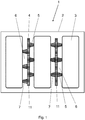
- Figure 1 shows a first embodiment of an energy storage system 1.
- the device 4 has a flat base 11, from which elevations 5 protrude in the direction of the storage cells 3.
- the device 4 is designed three-dimensionally.
- the elevations 5 are designed in the form of webs 7. Depressions 6 are formed between the elevations 5, so that insulating air cushions are created.
- the contact area of the elevations 5 to the memory cells 3 is small.
- the device 4 is made of elastomeric material, here a silicone rubber.
- the webs 7 can be arranged opposite one another or offset from one another on the base 11. The one on a main page of the The webs 7 attached to the base 11 can cross one another, so that the device 4 has a waffle-shaped profile.
- FIG 2 shows an embodiment according to Figure 1
- the elevations 5 or webs 7 are made of a different material than the base 11.
- the base 11 is made of a temperature-resistant and dimensionally stable material
- the elevations 5 are made of a temperature-resistant and elastic material.
- a thermoset, a mica film or a glass fabric, for example, comes into consideration as the material for the base 11, and a silicone rubber, for example, comes into consideration as the material for the elevations 5.
- FIG 3 shows an embodiment according to Figure 1 , wherein in the present embodiment the elevations 5 or webs 7 comprise a porous material.
- the elevations 5 are made of silicone rubber and provided with porous fillers, for example hollow glass spheres, expandable materials or aerogels.
- the porous fillers improve the thermal insulation.
- Figure 4 shows an embodiment according to Figure 1 , the elevations 5 or webs 7 of the device 4 protruding from the base 11 to different extents.
- the webs 7 are spaced apart from the storage cells 3 in the central region, so that the storage cells 3 can expand.
- Figure 5 shows an embodiment according to Figure 1 , wherein the elevations 5, or webs 7 of the device 4 are dimensioned differently.
- the webs 7 have a larger cross-sectional area, which are assigned to the edge 8 of the storage cell 3.
- the webs 7 have in the middle area this configuration has a smaller cross-sectional area.
- the webs 7 arranged on the inside can be deformed more easily, so that small forces are set when the storage cells 3 expand.
- Figure 6 shows a further embodiment of an energy storage system 1.
- the device 4 has a wave-shaped base 11, so that elevations 5 are created that rest against the storage cells 3 and depressions 6 that enclose an air cushion. To this extent, this device 4 is also designed three-dimensionally.
- the elevations 5 are designed in the form of webs 7.
- the device 4 is made of elastomeric material, here a silicone rubber.
- Figure 7 shows an embodiment according to Figure 6 , wherein the wave structure is designed such that the wave amplitude of the device 4 is greater in the section associated with the edge 8 of the memory cell 3 than in the inner region. As a result, the memory cells 3 can expand in this area.
- Figure 8 shows a further embodiment of an energy storage system 1.
- the device 4 has a flat base 11 from which knob-shaped elevations 5 protrude in the direction of the storage cells 3.
- the device 4 is designed three-dimensionally. Depressions 6 are formed between the elevations 5, so that insulating air cushions are created.
- the device 4 is made of elastomeric material, here a silicone rubber.
- the elevations 5 can be arranged opposite one another or offset from one another on the base 11.
- cup-shaped recesses can be made in the base 11, which form an air cushion.
- FIG 9 shows an energy storage system 1 with an integrated cooling device 12.
- the cooling device 12 comprises cooling elements 13 which are arranged between the storage cells 3 and which are connected to a central unit 14. This results in a sandwich structure in which a storage cell 3, a device 4 and a cooling element 13 are arranged alternately in the housing 2. As a result, a device 4 rests on one side of a storage cell 3 and a cooling element 13 rests on the other side.
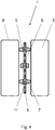
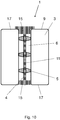
- Figure 10 shows an embodiment according to Figure 1 , the device 4 being provided with a surrounding frame 15.
- the frame 15 can run flush with the edge 17 of the storage cells 3 or protrude beyond the edge 17.
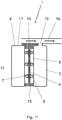
- Figure 11 shows an embodiment according to Figure 10 , wherein the device 4 extends at least in sections up to the end face 9 of the storage cell 3.
- the frame 15 is designed in such a way that it overlaps the end face 9 of the storage cell 3.
- the storage cell 3 has an emergency opening 10 which is arranged on the end face 9, the device 4 surrounding the emergency opening 10.
- the device 4 forms a seal between the emergency opening 10 of the storage cell 3 and the outlet channel 16, through which medium escaping from the emergency opening 10 of the storage cell 3 can be diverted.
Landscapes
- Chemical & Material Sciences (AREA)
- Chemical Kinetics & Catalysis (AREA)
- Electrochemistry (AREA)
- General Chemical & Material Sciences (AREA)
- Engineering & Computer Science (AREA)
- Manufacturing & Machinery (AREA)
- Inorganic Chemistry (AREA)
- Battery Mounting, Suspending (AREA)
- Secondary Cells (AREA)
- Electric Double-Layer Capacitors Or The Like (AREA)
Description
- Die Erfindung betrifft ein Energiespeichersystem, umfassend ein Gehäuse, in welchem mehrere Speicherzellen angeordnet sind, wobei die Speicherzellen mittels einer zwischen den Speicherzellen angeordneten Einrichtung thermisch voneinander isoliert sind.
- Energiespeichersysteme, insbesondere wiederaufladbare Speicher für elektrische Energie, sind vor allem in mobilen Systemen weit verbreitet. Wiederaufladbare Speicher für elektrische Energie werden beispielsweise in tragbaren elektronischen Geräten wie Smartphones oder Laptops eingesetzt. Des Weiteren werden wiederaufladbare Speicher für elektrische Energie vermehrt zum Bereitstellen von Energie für elektrisch angetriebene Fahrzeuge eingesetzt. Weitere Einsatzgebiete von elektrischen Energiespeichersystemen sind stationäre Anwendungen, beispielsweise in Backup-Systemen, in Netzwerkstabilisierungssystemen und zur Speicherung elektrischer Energie aus erneuerbaren Energiequellen.
- Ein häufig eingesetztes Energiespeichersystem ist dabei ein wiederaufladbarer Speicher in Form eines Lithium-Ionen-Akkumulators. Lithium-Ionen-Akkumulatoren weisen, wie andere wiederaufladbare Speicher für elektrische Energie auch, zumeist mehrere Speicherzellen auf, welche gemeinsam in einem Gehäuse verbaut sind. Mehrere elektrisch miteinander verbundene Speicherzellen bilden dabei ein Modul.
- Dabei erstreckt sich das Energiespeichersystem nicht nur auf Lithium-lonen-Akkumulatoren. Auch andere wiederaufladbare Batterie-Systeme wie Lithium-Schwefel-Batterien, Feststoff-Batterien oder Metall-Luft-Batterien sind denkbare Energiespeichersysteme. Des Weiteren kommen auch Superkondensatoren als Energiespeichersystem in Betracht.
- Energiespeichersysteme in Form von wiederaufladbaren Speichern weisen die höchste elektrische Kapazität nur in einem begrenzten Temperaturspektrum auf. Bei Über- bzw. Unterschreiten des optimalen Betriebstemperaturbereichs fällt die elektrische Kapazität des Speichers stark ab, bzw. die Funktionalität des Energiespeichers ist beeinträchtigt.
- Darüber hinaus können zu hohe Temperaturen zu einer Schädigung des Energiespeichersystems führen. In diesem Zusammenhang ist insbesondere bei Lithium-Ionen-Zellen das sogenannte thermische Durchgehen (thermal runaway) bekannt. Dabei werden in kurzer Zeit hohe thermische Energiemengen sowie gasförmige Abbauprodukte frei, woraus ein hoher Druck und hohe Temperaturen im Gehäuse resultieren. Dieser Effekt ist insbesondere problematisch bei Energiespeichersystemen mit hoher Energiedichte, wie sie beispielsweise zur Bereitstellung elektrischer Energie zur Bereitstellung von elektrisch angetriebenen Fahrzeugen erforderlich ist. Durch zunehmende Energiemengen einzelner Zellen und Erhöhung der Packungsdichte der in dem Gehäuse angeordneten Zellen vergrößert sich die Problematik des thermischen Durchgehens.
- Im Bereich einer durchgehenden Zelle können über eine Zeitdauer von etwa 30 Sekunden Temperaturen im Bereich von 600 °C entstehen. Die Einrichtung zum thermischen Isolieren muss einer derartigen Beanspruchung standhalten und den Energieübergang auf Nachbarzellen so reduzieren, dass die Temperaturbelastung der Nachbarzellen lediglich etwa 150 °C beträgt. Anschließend ist es erforderlich, den Energiespeicher, beziehungsweise die schadhafte Zelle auszutauschen. Insofern ist es zwar zulässig, dass sich die Einrichtung während dieses Vorgangs irreversibel verändert. Wesentlich ist die Begrenzung der Energieübertragung auf Nachbarzellen, um zu verhindern, dass auch diese thermisch durchgehen.
- Um die Folgen einer Erhitzung abzumildern ist es aus dem Stand der Technik bekannt, zwischen den Zellen Phasenwechselmaterial einzusetzten, siehe z.B.
US 2011/159340 A1 undUS 5 578 393 A . - Der Erfindung liegt die Aufgabe zugrunde, ein Energiespeichersystem bereitzustellen, welches eine hohe Betriebssicherheit aufweist.
- Diese Aufgabe wird mit den Merkmalen von Anspruch 1 gelöst. Auf vorteilhafte Ausgestaltungen nehmen die Unteransprüche Bezug.
- Das erfindungsgemäße Energiespeichersystem umfasst ein Gehäuse, in welchem mehrere Speicherzellen angeordnet sind, wobei die Speicherzellen mittels einer zwischen den Speicherzellen angeordneten Einrichtung thermisch voneinander isoliert sind, wobei die Einrichtung derart ausgebildet ist, dass die Speicherzellen voneinander beabstandet sind, wobei die Einrichtung aus einem temperaturbeständigem Werkstoff ausgebildet ist. Die Zellen können hierbei prismatische Zellen oder Pouch-Zellen sein. Die Erfindung erlaubt darüber hinaus auch eine Adaption auf Speichersysteme mit Rundzellen.
- Dadurch, dass die Speicherzellen voneinander beabstandet sind, kann eine direkte Wärmeübertragung von einer Speicherzelle auf eine benachbarte Speicherzelle verhindert werden. Durch die zwischen den Speicherzellen angeordnete Einrichtung verringert sich die Wärmeübertragung nochmals. Vorzugsweise ist die Einrichtung ferner elastisch ausgebildet. Dadurch kann die Einrichtung etwaigen Dimensionsänderungen der Speicherzellen folgen und so verhindern, dass sich innerhalb der Speicherzellen ein unzulässig hoher Druck aufbaut. Durch die temperaturbeständige Ausgestaltung der Einrichtung kann ferner verhindert werden, dass die Einrichtung auch bei einem thermischen Durchgehen einer Speicherzelle zerstört wird, so dass ein Übergreifen des thermischen Durchgehens auf benachbarte Speicherzellen verhindert werden kann. Die elastische Ausgestaltung kann durch Materialwahl und/oder Formgebung der Einrichtung realisiert werden.
Weiter weist die Einrichtung Erhebungen und Vertiefungen auf.
Eine derartige Strukturierung ergibt sich beispielsweise, wenn die Einrichtung waffelförmig strukturiert ist. Ferner ergibt sich eine derartige Ausgestaltung, wenn die Einrichtung eine wellenförmige Profilierung aufweist. - Ferner kommen Materialien in der Einrichtung zum Einsatz, welche bei Erwärmung über 200°C einer endothermen Reaktion unterliegen, beispielsweise durch Umkristallisation oder dem Freisetzen von Kristallwasser. Eine solche Ausgestaltung führt zu einem zusätzlichen Wärmepolster und verlangsamt den Wärmeübergang zwischen den Zellen. Derartige Materialien sind beispielsweise anorganische Salze wie Nitrate oder Carbonate. Denkbar sind auch Hydroxide oder Oxy-Hydroxide, die unter erhöhten Temperaturen Wasser abspalten können. So werden typischerweise bei der Wasserabspaltung von Mg(OH)2 bei Temperaturen oberhalb von etwa 350°C Energiemengen von etwa 1.200 kJ/kg absorbiert. Bei der Wasserabspaltung aus Al(OH)3 werden bei Temperaturen oberhalb von etwa 250°C Energiemengen von um 1.100 kJ/kg absorbiert.
- Besonders bevorzugt weist die Einrichtung eine geringe Wärmeleitfähigkeit auf. Die Wärmeleitfähigkeit der Einrichtung beträgt bevorzugt höchstens 0,1 W/mK. In diesem Zusammenhang ist insbesondere relevant, den Wärmeübergang zwischen den Zellen zu minimieren. Dabei kann die Einrichtung beispielsweise aus einem Werkstoff mit geringer Wärmeleitfähigkeit ausgebildet sein. Alternativ oder zusätzlich kann die Einrichtung eine Formgebung aufweisen, welche den Wärmeübergang verringert. Das kann beispielsweise durch Verringerung der Kontaktfläche, Labyrinth-Strukturen und dergleichen erfolgen.
- Die Einrichtung ist vorzugsweise flächig ausgebildet, so dass sich die Speicherzellen entlang der einander zugewandten Hauptseiten an der Einrichtung abstützen können. Dadurch ergibt sich eine mechanisch stabile Anordnung der Speicherzellen. Bei dieser Ausgestaltung vereinfacht sich auch die Montage des Energiespeichers.
- Die Einrichtung kann dreidimensional strukturiert sein. Dadurch bilden sich Zonen der Einrichtung, die an den Speicherzellen anliegen und Zonen, welche von den Speicherzellen beabstandet sind. Es bilden sich Hohlräume, welche die thermische Isolierung verbessern.
- Bei einer waffelförmigen Strukturierung der Einrichtung ergeben sich einander kreuzende Erhebungen, welche an den Speicherzellen anliegen und napfförmige Vertiefungen, welche zwischen den Erhebungen angeordnet sind. Dabei sind die Vertiefungen nicht strömungsleitend miteinander verbunden. Es bilden sich kleine Hohlraumzellen aus, welche eine hervorragende thermische Isolierung aufweisen. Im Zusammenhang mit der Verwendung eines elastischen Werkstoffs ist bei dieser Ausgestaltung vorteilhaft, dass die Hohlraumzellen zumindest während der Montage als Saugnäpfe fungieren können, so dass die Einrichtung durch einfaches Andrücken an den Zellen fixiert ist. Dadurch vereinfacht sich die Montage des Energiespeichers.
- Dabei können die Hohlraumzellen einen rechteckigen, mehreckigen oder runden Querschnitt aufweisen.
- Es ist auch denkbar die Einrichtung wellenförmig zu profilieren. Dabei ergeben sich abwechselnd Erhebungen und Vertiefungen, wobei die Speicherzellen linienförmig entlang der Erhebungen und Vertiefungen an der Einrichtung anliegen. Die Vertiefungen können durchströmt sein. Dies ist insbesondere dann vorteilhaft, wenn durch eine starke Temperaturänderung das in den Vertiefungen aufgenommene Gas eine große Volumenänderung erfährt. Das Gas kann in den durch die Erhebungen und die Vertiefungen gebildeten Kanälen abtransportiert werden.
- Alternativ ist es denkbar, dass die Einrichtung hervorstehende Stege aufweist. Dadurch bilden sich großflächige Zonen aus, welche von den Speicherzellen beabstandet sind. Der Kontaktbereich der Einrichtung zu den Speicherzellen ist verhältnismäßig klein.
- In diesem Zusammenhang ist insbesondere denkbar, für die Stege ein anderes Material auszuwählen als für die übrigen Bereiche der Einrichtung. Bei dieser Ausgestaltung unterliegen die Stege der größten Temperaturbelastung, so dass die Stege aus einem besonders temperaturbeständigen Werkstoff gewählt sein können. Die übrigen Bereiche der Einrichtung können hingegen aus kostengünstigerem weniger temperaturbeständigem Material gewählt sein.
- Ferner ist denkbar, dass die Einrichtung punktförmig hervorstehende Erhebungen aufweist. Derartige Erhebungen können insbesondere als Noppen ausgebildet sein, die aus der Oberfläche der Erhebungen hervorstehen. Bei dieser Ausgestaltung ergibt sich eine geringe Anlagefläche der Einrichtung an die Speicherzelle, wodurch die Wärmeübertragung begrenzt ist. Im Fall des thermischen Durchgehens wird das Material der Einrichtung lediglich im Bereich der Noppen stark thermisch beansprucht. Anfallendes Gas kann in den Zwischenräumen zwischen den Noppen abtransportiert werden. Dabei kann die Einrichtung derart ausgestaltet sein, dass auch bei ausgebauchten Zellen infolge Ladungszustand und Alterung ein Luftpolster zwischen Einrichtung und Speicherzelle gegeben ist. Die Noppen können aus einem anderen Material bestehen als die Basis der Einrichtung. In diesem Zusammenhang ist es vorteilhaft, für die Noppen einen besonders temperaturbeständigen Werkstoff zu wählen. Dabei ist der Materialbedarf zur Ausgestaltung der Noppen gering, so dass ein kostenintensiver Werkstoff gewählt werden kann.
- Eine elastisch ausgestaltete Einrichtung stellt dabei im Neuzustand der Speicherzellen einen definierten Formschluss zwischen der Einrichtung und den Speicherzellen her und besitzt im gealterten Zustand der Zellen immer noch eine Porosität, um die thermische Isolation sicherzustellen.
- Die Einrichtung kann derart ausgebildet sein, dass sich zwischen dem dem Rand der Speicherzellen zugeordneten Abschnitt der Einrichtung ein größerer Anpressdruck der Einrichtung an die Speicherzelle ergibt als an den übrigen Abschnitten. Bei dieser Ausgestaltung kann die Einrichtung am Außenumfang Stege aufweisen, welche weiter hervorstehen, als die Stege im Inneren der Einrichtung. Dadurch liegen die äußeren Bereiche der Einrichtung stets an den Speicherzellen an. Insbesondere Lithium-Ionen-Zellen unterliegen sowohl durch Ladevorgänge als auch durch Alterungsprozesse einer Volumenänderung, wobei sich die Speicherzellen entlang der Hauptseiten ausbauchen können. Dadurch, dass die Einrichtung am Außenumfang mit größerer Vorspannung an den Speicherzellen anliegt als an den inneren Bereichen, können sich die Speicherzellen ausdehnen, wobei der Anpressdruck der Speicherzellen an die Einrichtung in den inneren Bereichen allmählich ansteigt. Die Einrichtung kann sich zumindest abschnittsweise bis auf die Stirnseite der Speicherzelle erstrecken. Häufig sind Speicherzellen quaderförmig ausgebildet und weisen einander zugewandte Hauptseiten auf.
- Eine ähnliche Wirkung kann erzielt werden, wenn die Einrichtung im Inneren einen geringeren Widerstand gegen Kompression aufweist als im Randbereich. Dies kann zum Beispiel durch dünnere Strukturen realisiert werden.
- Erstreckt sich die Einrichtung zumindest abschnittsweise bis auf die Stirnseiten der Speicherzellen, kann die Einrichtung in diesen Bereichen eine Abdichtfunktion übernehmen und die Speicherzellen beispielsweise gegenüber dem Gehäuse abdichten.
- Die Speicherzelle kann eine Notöffnung aufweisen, welche auf der Stirnseite angeordnet ist, wobei die Einrichtung die Notöffnung umgibt. Insbesondere prismatische Lithium-Ionen-Zellen weisen derartige Notöffnungen auf. Diese können in Form einer Sollbruchstelle, also einer gezielten Materialschwächung oder auch in Form einer Berstscheibe vorliegen. Steigt der Innendruck der Speicherzelle stark an und überschreitet schließlich eine vorgegebene Grenze, öffnet sich die Notöffnung und der innerhalb der Speicherzelle vorliegende Druck wird abgebaut. Die emittierten heißen Gase werden in der zumeist durch einen Sammel- oder Austrittskanal gezielt abgeleitet. Dieser überdeckt vorteilhafterweise die Notöffnungen der benachbarten Zellen. Hierdurch kann eine vollständige Zerstörung des gesamten Energiespeichersystems verhindert werden. Die die Notöffnung umgebende Einrichtung bildet dabei eine zusätzliche Abdichtung zum Austrittskanal und ermöglicht ein gezieltes Ableiten des aus der Speicherzelle austretenden Gases. Beispielsweise kann das austretende Gas in einen Austrittskanal geleitet werden. Die Einrichtung dichtet dann zusätzlich zwischen der Speicherzelle und dem Austrittskanal ab.
- Der Bereich der dem Austrittskanal zugeordnet Abschnitt der Einrichtung kann dabei ebenfalls strukturiert sein. Dies gewährleistet im Falle einer Notöffnung eine thermische Isolation in diesem Bereich. Denkbar ist aber auch eine ebene Ausführung oder eine Ausführung, bei der die Konturen als zwischen Sollbruchstelle und dem Austrittskanal angeordnete Dichtelemente ausgestaltet sind, beispielsweise in Form von Dichtlippen.
- Die Einrichtung kann zumindest abschnittsweise aus elastomerem Werkstoff ausgebildet sein. Hierbei ist vorteilhaft, dass die Einrichtung elastische Eigenschaften aufweist und insbesondere Formänderungen der Speicherzellen durch Formänderungen der Einrichtung aufgefangen werden können. Des Weiteren weisen elastomere Werkstoffe häufig nur ein geringes Wärmeleitvermögen auf. Ein vorteilhafter elastomerer Werkstoff ist beispielsweise Silikon-Kautschuk. Neben der geringen Wärmeleitfähigkeit zeichnet sich Silikon-Kautschuk dadurch aus, dass dieser sehr temperaturbeständig ist. Alternativ wäre es denkbar, die Einrichtung aus Flur-Kautschuk (FKM) auszubilden. Im Vergleich zu Silikon-Kautschuk ergibt sich hierbei aber ein problematisches Brandverhalten. Für thermisch besonders beanspruchte Anwendungen kommen auch Fluor-Silikone in Betracht.
- Zusätzlich können dem Material anorganische Füllstoffe beigemischt werden, die die Temperaturbeständigkeit von Elastomeren und Kunststoffen verbessern.
- Ferner können dem Material thermisch isolierende Füllstoffe zugemischt werden, die eine intrinsische Porosität und damit ein intrinsisches Gaspolster im Inneren des Materials erzeugen. Diese intrinsische Porosität liegt zusätzlich zu den oben beschriebenen makroskopischen, durch die Struktur dargestellten Hohlräumen vor. In diesem Zusammenhang sind beispielweise Glas-Hohlkugeln und hochporöse anorganische Materialien wie beispielsweise Aerosile, Blähstoffe oder Aerogele denkbar.
- In einer nicht zur Erfindung gehörenden Ausgestaltung könnte das Material Füllstoffe enthalten, welche als latente Wärmespeicher fungieren. Derartige latente Wärmespeichermaterialien sind beispielsweise Phasenwechselmaterialien, wobei das Material vorzugsweise so gewählt ist, dass der Phasenübergang zwischen fest und flüssig mindestens 200°C beträgt.
- Bei der Verwendung von Pouch-Zellen, deren Gehäuse eine thermische Belastbarkeit aufweisen, welche geringer ist als die von prismatischen oder Rundzellen, können auch Materialien zum Einsatz kommen, deren Phasenübergang bei noch niedrigeren Temperaturen liegt, beispielsweise bei einer Temperatur von 150°C. Denkbar ist darüber hinaus die Verwendung einer Kombination mehrerer latent wärmespeichernder Substanzen. Beispielsweise ist es denkbar, eine erste Substanz mit einem Phasenübergang bei 300°C mit einer zweiten Substanz mit einem Phasenübergang von 200°C zu kombinieren.
- Sowohl das Phasenwechselmaterial als auch die zuletzt genannten Salze können gekapselt oder in porösen Füllstoffen in die Einrichtung eingebunden sein. Bei Verwendung von Substanzen, deren Schmelzpunkt oder Umwandlungstemperatur oberhalb der der Prozesstemperatur von typischerweise etwa 180°C liegt, kann eine Kapselung entfallen. Dadurch erhöht sich der potentielle Anteil an thermisch wirksamen Substanzen. Denkbar, aber nicht notwendigerweise benötigt, sind hierbei Massenanteile über 50%.
- Denkbar ist auch, dass die Füllstoffe in eine flächige Matrix eingebracht sind, wobei die Matrix Bestandteil der Einrichtung ist. Die Matrix kann beispielsweise aus thermisch beständigem Vliesstoff bestehen. Diese Ausgestaltung ermöglicht eine homogene Verteilung der Füllstoffe über die Fläche der Einrichtung, wobei große Mengen Füllstoff in die Matrix einbringbar sind. Die Füllstoffe können dabei durch gängige Prozesse wie Rakeln oder Foulardieren in die flächige Matrix eingebracht werden. Die Matrix ist vorzugsweise in ein Elastomer eingebettet.
- Aufgrund der anzustrebenden hohen Packungsdichte soll die Einrichtung einen möglichst geringen Platzbedarf aufweisen. Dazu soll die Einrichtung so dünn wie möglich ausgestaltet sein. Vorzugsweise besitzt die Einrichtung im unbelasteten Zustand eine Dicke von höchstens 5 mm, vorzugsweise beträgt die Dicke weniger als 1,5 mm. Denkbar ist es, eine Dicke der Einrichtung im Bereich von 0,3 mm oder weniger zu erzielen. Insbesondere für mobile Anwendungen kann in diesem Fall die flächige Basis der Einrichtung eine Dicke von 0,2 mm aufweisen. Die Dicke der an den Speicherzellen anliegenden beidseitigen Erhebungen beläuft sich in diesem Fall auf 0,15 mm.
- Einige Ausgestaltungen des erfindungsgemäßen Energiespeichersystems werden nachfolgend anhand der Figuren näher erläutert. Diese zeigen, jeweils schematisch:
- Fig. 1
- ein Energiespeichersystem mit einer Einrichtung mit Abstandshaltern;
- Fig. 2
- ein Energiespeichersystem gemäß
Figur 1 mit abweichender Werkstoffkonfiguration; - Fig. 3
- ein Energiespeichersystem gemäß
Figur 1 mit porösen Abstandshaltern; - Fig. 4
- eine Einrichtung mit unterschiedlich hervorstehenden Abstandshaltern;
- Fig. 5
- eine Einrichtung mit unterschiedlich dimensionierten Abstandshaltern;
- Fig. 6
- eine wellenförmige Einrichtung;
- Fig. 7
- eine wellenförmige Einrichtung mit wechselndem Wellenverlauf;
- Fig. 8
- eine Einrichtung mit noppenförmigen Vorsprüngen;
- Fig. 9
- ein Energiespeichersystem mit Kühleinrichtung;
- Fig. 10
- eine Einrichtung mit umlaufendem Befestigungsrahmen;
- Fig. 11
- ein Energiespeichersystem mit Notöffnung und Austrittskanal.
- Die Figuren zeigen ein Energiespeichersystem 1, zum Speichern elektrischer Energie. Vorliegend ist das Energiespeichersystem 1 als Akkumulator, beispielsweise als Lithium-Ionen-Akkumulator ausgebildet. Das Energiespeichersystem 1 umfasst ein Gehäuse 2, in welchem mehrere Speicherzellen 3 angeordnet sind. Die Speicherzellen 3 können dabei in Form von prismatischen Zellen vorliegen und nebeneinander in dem Gehäuse 2 angeordnet sein.
- Die Speicherzellen 3 sind mittels einer zwischen den Speicherzellen 3 angeordneten Einrichtung 4 thermisch voneinander isoliert. Dabei ist die Einrichtung 4 derart ausgebildet, dass die Speicherzellen 3 voneinander beabstandet sind. Des Weiteren ist die Einrichtung 4 aus temperaturbeständigem Werkstoff ausgebildet.
-
Figur 1 zeigt eine erste Ausgestaltung eines Energiespeichersystems 1. Bei dieser Ausgestaltung weist die Einrichtung 4 eine flächig ausgebildete Basis 11 auf, aus welcher Erhebungen 5 in Richtung der Speicherzellen 3 ragen. Insofern ist die Einrichtung 4 dreidimensional ausgebildet. Die Erhebungen 5 sind in Form von Stegen 7 ausgebildet. Zwischen den Erhebungen 5 bilden sich Vertiefungen 6 aus, so dass isolierende Luftpolster entstehen. Die Kontaktfläche der Erhebungen 5 zu den Speicherzellen 3 ist klein. Die Einrichtung 4 ist aus elastomerem Werkstoff, hier einem Silikon-Kautschuk ausgebildet. Die Stege 7 können einander gegenüberliegend oder versetzt zueinander auf der Basis 11 angeordnet sein. Die auf einer Hauptseite der Basis 11 angebrachten Stege 7 können einander kreuzen, so dass sich eine waffelförmige Profilierung der Einrichtung 4 ergibt. -
Figur 2 zeigt eine Ausgestaltung gemäßFigur 1 , wobei bei der vorliegenden Ausgestaltung die Erhebungen 5, beziehungsweise Stege 7 aus einem anderen Material bestehen als die Basis 11. Dabei besteht die Basis 11 aus einem temperaturbeständigen und formbeständigen Werkstoff, während die Erhebungen 5 aus einem temperaturbeständigen und elastischen Werkstoff bestehen. Als Material für die Basis 11 kommt dabei beispielsweise ein Duromer, eine Glimmerfolie oder ein Glasgewebe in Betracht und als Material für die Erhebungen 5 kommt beispielsweise ein Silikon-Kautschuk in Betracht. -
Figur 3 zeigt eine Ausgestaltung gemäßFigur 1 , wobei bei der vorliegenden Ausgestaltung die Erhebungen 5, beziehungsweise Stege 7 ein poröses Material umfassen. Gemäß einer vorteilhaften Ausgestaltung sind die Erhebungen 5 aus Silikon-Kautschuk ausgebildet und mit porösen Füllstoffen, beispielsweise hohlen Glaskugeln, Blähmaterialien oder Aerogelen versehen. Die porösen Füllstoffe verbessern die thermische Isolierung. -
Figur 4 zeigt eine Ausgestaltung gemäßFigur 1 , wobei die Erhebungen 5, beziehungsweise Stege 7 der Einrichtung 4 unterschiedlich weit von der Basis 11 abragen. Dabei stehen die Stege 7, die dem Rand 8 der Speicherzelle 3 zugeordnet sind, weiter hervor. Im Mittelbereich sind die Stege 7 bei dieser Ausgestaltung von den Speicherzellen 3 beabstandet, so dass sich die Speicherzellen 3 ausdehnen können. -
Figur 5 zeigt eine Ausgestaltung gemäßFigur 1 , wobei die Erhebungen 5, beziehungsweise Stege 7 der Einrichtung 4 unterschiedlich dimensioniert sind. Dabei weisen die Stege 7 eine größere Querschnittsfläche auf, die dem Rand 8 der Speicherzelle 3 zugeordnet sind. Im Mittelbereich weisen die Stege 7 bei dieser Ausgestaltung eine geringere Querschnittsfläche auf. Dadurch lassen sich die innen angeordneten Stege 7 leichter verformen, so dass sich bei einer Ausdehnung der Speicherzellen 3 geringe Kräfte einstellen. -
Figur 6 zeigt eine weitere Ausgestaltung eines Energiespeichersystems 1. Bei dieser Ausgestaltung weist die Einrichtung 4 eine wellenförmig ausgebildete Basis 11 auf, so dass Erhebungen 5 entstehen, welche an den Speicherzellen 3 anliegen und Vertiefungen 6, welche ein Luftpolster einschließen. Insofern ist auch diese Einrichtung 4 dreidimensional ausgebildet. Die Erhebungen 5 sind in Form von Stegen 7 ausgebildet. Die Einrichtung 4 ist aus elastomerem Werkstoff, hier einem Silikon-Kautschuk ausgebildet. -
Figur 7 zeigt eine Ausgestaltung gemäßFigur 6 , wobei die Wellenstruktur so ausgebildet ist, dass die Wellenamplitude der Einrichtung 4 in dem dem Rand 8 der Speicherzelle 3 zugeordneten Abschnitt größer ist als in dem inneren Bereich. Dadurch können sich die Speicherzellen 3 in diesem Bereich ausdehnen. -
Figur 8 zeigt eine weitere Ausgestaltung eines Energiespeichersystems 1. Bei dieser Ausgestaltung weist die Einrichtung 4 eine flächig ausgebildete Basis 11 auf, aus welcher noppenförmige Erhebungen 5 in Richtung der Speicherzellen 3 ragen. Insofern ist die Einrichtung 4 dreidimensional ausgebildet. Zwischen den Erhebungen 5 bilden sich Vertiefungen 6 aus, so dass isolierende Luftpolster entstehen. Die Einrichtung 4 ist aus elastomerem Werkstoff, hier einem Silikon-Kautschuk ausgebildet. Die Erhebungen 5 können einander gegenüberliegend oder versetzt zueinander auf der Basis 11 angeordnet sein. - Alternativ können in die Basis 11 napfförmige Vertiefungen eingebracht sein, welche ein Luftpolster bilden.
-
Figur 9 zeigt ein Energiespeichersystem 1 mit einer integrierten Kühleinrichtung 12. Die Kühleinrichtung 12 umfasst Kühlelemente 13, welche zwischen den Speicherzellen 3 angeordnet sind und welche mit einer Zentraleinheit 14 verbunden sind. Dabei ergibt sich ein Sandwich-Aufbau, bei welchem abwechselnd eine Speicherzelle 3, eine Einrichtung 4 und ein Kühlelement 13 in dem Gehäuse 2 angeordnet sind. Dadurch liegt an einer Seite einer Speicherzelle 3 eine Einrichtung 4 und an der anderen Seite ein Kühlelement 13 an. -
Figur 10 zeigt eine Ausgestaltung gemäßFigur 1 , wobei die Einrichtung 4 mit einem umlaufenden Rahmen 15 versehen ist. Der Rahmen 15 kann dabei bündig zu dem Rand 17 der Speicherzellen 3 verlaufen oder über den Rand 17 überstehen. -
Figur 11 zeigt eine Ausgestaltung gemäßFigur 10 , wobei sich die Einrichtung 4 zumindest abschnittsweise bis auf die Stirnseite 9 der Speicherzelle 3 erstreckt. Dabei ist der Rahmen 15 so ausgebildet, dass dieser die Stirnseite 9 der Speicherzelle 3 überlappt. Die Speicherzelle 3 weist eine Notöffnung 10 auf, welche auf der Stirnseite 9 angeordnet ist, wobei die Einrichtung 4 die Notöffnung 10 umgibt. Dadurch bildet die Einrichtung 4 eine Abdichtung zwischen der Notöffnung 10 der Speicherzelle 3 und dem Austrittskanal 16, durch welchen aus der Notöffnung 10 der Speicherzelle 3 austretendes Medium abgeleitet werden kann.
Claims (12)
- Energiespeichersystem (1), umfassend ein Gehäuse (2), in welchem mehrere Speicherzellen (3) angeordnet sind, wobei die Speicherzellen (3) mittels einer zwischen den Speicherzellen (3) angeordneten Einrichtung (4) thermisch voneinander isoliert sind, wobei die Einrichtung (4) derart ausgebildet ist, dass die Speicherzellen (3) voneinander beabstandet sind, wobei die Einrichtung (4) aus temperaturbeständigem Werkstoff ausgebildet ist.dadurch gekennzeichnet, dassdie Einrichtung (4) Erhebungen (5) und Vertiefungen (6) aufweist und dass die Einrichtung (4) ein Material enthält, welches bei Überschreiten einer Temperatur von 200°C einer endothermen chemischen Umwandlung unterliegt.
- Energiespeichersystem nach Anspruch 1, dadurch gekennzeichnet, dass die Einrichtung (4) dreidimensional strukturiert ist.
- Energiespeichersystem nach einem der Ansprüche 1 bis 2, dadurch gekennzeichnet, dass die Einrichtung (4) hervorstehende Stege (7) aufweist.
- Energiespeichersystem nach einem der Ansprüche 1 bis 3, dadurch gekennzeichnet, dass die Einrichtung (4) waffelförmig strukturiert ist.
- Energiespeichersystem nach einem der Ansprüche 1 bis 3, dadurch gekennzeichnet, dass die Einrichtung (4) eine wellenförmige Profilierung aufweist.
- Energiespeichersystem nach einem der Ansprüche 1 bis 3, dadurch gekennzeichnet, dass die Einrichtung (4) noppenförmige Erhebungen aufweist.
- Energiespeichersystem nach einem der Ansprüche 2 bis 6, dadurch gekennzeichnet, dass die Strukturierung derart ausgebildet ist, dass sich zwischen dem dem Rand (8) der Speicherzellen (3) zugeordneten Abschnitt der Einrichtung (4) ein größerer Anpressdruck der Einrichtung (4) an die Speicherzelle (3) ergibt als an den übrigen Abschnitten.
- Energiespeichersystem nach einem der Ansprüche 1 bis 7, dadurch gekennzeichnet, dass sich die Einrichtung (4) zumindest abschnittsweise bis auf die Stirnseite (9) der Speicherzelle (3) erstreckt.
- Energiespeichersystem nach Anspruch 8, dadurch gekennzeichnet, dass die Speicherzelle (3) eine Notöffnung (10) aufweist, welche auf der Stirnseite (9) angeordnet ist, wobei die Einrichtung (4) die Notöffnung (10) umgibt.
- Energiespeichersystem nach einem der Ansprüche 1 bis 9, dadurch gekennzeichnet, dass die Einrichtung (4) zumindest abschnittsweise aus elastomerem Werkstoff ausgebildet ist.
- Energiespeichersystem nach Anspruch 10, dadurch gekennzeichnet, dass die Einrichtung (4) aus Silikon-Kautschuk oder Fluor-Silikon-Kautschuk ausgebildet ist.
- Energiespeichersystem nach einem der Ansprüche 1 bis 11, dadurch gekennzeichnet, dass der Einrichtung (4) eine Kühleinrichtung (12) zugeordnet ist.
Applications Claiming Priority (2)
| Application Number | Priority Date | Filing Date | Title |
|---|---|---|---|
| DE102017008102.6A DE102017008102A1 (de) | 2017-08-29 | 2017-08-29 | Energiespeichersystem |
| PCT/EP2018/070964 WO2019042698A1 (de) | 2017-08-29 | 2018-08-02 | Energiespeichersystem |
Publications (2)
| Publication Number | Publication Date |
|---|---|
| EP3676890A1 EP3676890A1 (de) | 2020-07-08 |
| EP3676890B1 true EP3676890B1 (de) | 2021-11-03 |
Family
ID=63294191
Family Applications (1)
| Application Number | Title | Priority Date | Filing Date |
|---|---|---|---|
| EP18758545.0A Active EP3676890B1 (de) | 2017-08-29 | 2018-08-02 | Energiespeichersystem |
Country Status (8)
| Country | Link |
|---|---|
| US (1) | US11374279B2 (de) |
| EP (1) | EP3676890B1 (de) |
| JP (1) | JP6918213B2 (de) |
| KR (2) | KR20200033289A (de) |
| CN (1) | CN111052437B (de) |
| DE (1) | DE102017008102A1 (de) |
| ES (1) | ES2903271T3 (de) |
| WO (1) | WO2019042698A1 (de) |
Cited By (2)
| Publication number | Priority date | Publication date | Assignee | Title |
|---|---|---|---|---|
| WO2025228972A1 (de) * | 2024-05-02 | 2025-11-06 | Nies Klaus Dieter | Batterieanordnung mit dreidimensionale kunststoffstruktur als trennelement |
| EP4726882A1 (de) * | 2024-10-10 | 2026-04-15 | Prime Planet Energy & Solutions, Inc. | Modul zur speicherung elektrischer energie und dafür verwendeter abstandshalter |
Families Citing this family (48)
| Publication number | Priority date | Publication date | Assignee | Title |
|---|---|---|---|---|
| JP7491903B2 (ja) * | 2019-03-27 | 2024-05-28 | 三洋電機株式会社 | 電源装置と電動車両 |
| WO2020196190A1 (ja) * | 2019-03-28 | 2020-10-01 | 株式会社Gsユアサ | 蓄電装置 |
| JP7649238B2 (ja) * | 2019-06-28 | 2025-03-19 | 三洋電機株式会社 | 電源装置とこの電源装置を備える電動車両及び蓄電装置 |
| CN113906624A (zh) * | 2019-06-28 | 2022-01-07 | 三洋电机株式会社 | 电源装置和具有该电源装置的电动车辆以及蓄电装置 |
| DE102019121849A1 (de) * | 2019-08-14 | 2021-02-18 | Carl Freudenberg Kg | Energiespeichersystem |
| DE102019121850A1 (de) * | 2019-08-14 | 2021-02-18 | Carl Freudenberg Kg | Energiespeichersystem |
| KR102807685B1 (ko) * | 2019-10-15 | 2025-05-13 | 주식회사 엘지에너지솔루션 | 배터리 팩 |
| DE102019129473A1 (de) * | 2019-10-31 | 2021-05-06 | Bayerische Motoren Werke Aktiengesellschaft | Vermeidung eines thermischen Durchgehens in einem Zellmodul mit mehreren Batteriezellen |
| JP2021106146A (ja) * | 2019-12-27 | 2021-07-26 | 古河電池株式会社 | 空気電池ユニット |
| JP7562228B2 (ja) * | 2020-01-11 | 2024-10-07 | 株式会社イノアックコーポレーション | 緩衝材 |
| CN115004455B (zh) * | 2020-01-31 | 2025-09-02 | Sk新能源株式会社 | 电池模块 |
| JP7292231B2 (ja) * | 2020-03-06 | 2023-06-16 | ニチアス株式会社 | 電池用断熱材及び電池 |
| US12424698B2 (en) * | 2020-03-31 | 2025-09-23 | Sanyo Electric Co., Ltd. | Power supply device, electric vehicle comprising power supply device, and power storage device |
| US20230135817A1 (en) * | 2020-03-31 | 2023-05-04 | Sanyo Electric Co., Ltd. | Power supply device, electric vehicle provided with power supply device, and power storage device |
| KR102890553B1 (ko) * | 2020-06-29 | 2025-11-26 | 주식회사 엘지에너지솔루션 | 연쇄발화를 방지하는 전지 모듈 제조방법 |
| KR102773568B1 (ko) * | 2020-07-22 | 2025-02-27 | 주식회사 엘지에너지솔루션 | 전지 모듈, 전지 모듈 시스템 및 전지 모듈을 포함하는 전지 팩 |
| KR102869313B1 (ko) * | 2020-08-20 | 2025-10-13 | 주식회사 엘지에너지솔루션 | 단열 부재를 포함하는 배터리 모듈 |
| KR102949551B1 (ko) | 2020-09-10 | 2026-04-06 | 주식회사 엘지에너지솔루션 | 배터리 모듈들 간의 열확산 방지구조를 적용한 배터리 팩 |
| WO2022138779A1 (ja) * | 2020-12-22 | 2022-06-30 | 三菱ケミカル株式会社 | 組電池 |
| US20240072349A1 (en) * | 2021-01-22 | 2024-02-29 | Panasonic Energy Co., Ltd | Battery pack |
| JP2022129775A (ja) * | 2021-02-25 | 2022-09-06 | パナソニックIpマネジメント株式会社 | 蓄電モジュールおよび蓄電モジュールの製造方法 |
| DE102021118437B3 (de) | 2021-07-16 | 2023-01-05 | OERLIKON FRICTION SYSTEMS (GERMANY) GmbH | Thermische Isolationsmatte für Batteriesysteme |
| JP7573500B2 (ja) * | 2021-08-13 | 2024-10-25 | 信越ポリマー株式会社 | 延焼防止部材、セルユニットおよびバッテリー |
| JP7503529B2 (ja) * | 2021-08-27 | 2024-06-20 | プライムアースEvエナジー株式会社 | 電池モジュールおよびスペーサ |
| JP7724662B2 (ja) * | 2021-08-31 | 2025-08-18 | 住友理工株式会社 | 断熱弾性部材 |
| DE102021131307A1 (de) | 2021-11-29 | 2023-06-01 | Zentrum für Sonnenenergie- und Wasserstoff-Forschung Baden-Württemberg, Stiftung des bürgerlichen Rechts | Propagationsbarriere mit variabler Kompressibilität durch Strukturierung |
| DE102021132072A1 (de) | 2021-12-06 | 2023-06-07 | Carl Freudenberg Kg | Energiespeichersystem |
| EP4395013A4 (de) * | 2022-01-27 | 2025-01-22 | Contemporary Amperex Technology (Hong Kong) Limited | Batterie, stromverbrauchende vorrichtung, verfahren zur herstellung der batterie und vorrichtung zur herstellung der batterie |
| US20250132413A1 (en) * | 2022-02-04 | 2025-04-24 | Dic Corporation | Secondary battery module |
| US20230275299A1 (en) | 2022-02-25 | 2023-08-31 | Inventus Power, Inc. | Battery pack with thermal protection |
| EP4510342A4 (de) * | 2022-04-14 | 2026-04-01 | Nok Corp | Batteriepolstermaterial |
| CN114851460B (zh) * | 2022-04-25 | 2023-06-20 | 蜂巢能源科技股份有限公司 | 渐变弹性材料及其生产模具和生产方法以及方型电池 |
| WO2023215966A1 (en) * | 2022-05-11 | 2023-11-16 | Volinergy Technologies Inc. | Battery having insulating separators and thermal conductors for cooling |
| JP7616153B2 (ja) * | 2022-05-26 | 2025-01-17 | トヨタ自動車株式会社 | 電池パックおよび車両 |
| CN114784441B (zh) * | 2022-06-22 | 2022-10-25 | 宁德时代新能源科技股份有限公司 | 电池以及用电装置 |
| DE102022124442A1 (de) | 2022-09-23 | 2024-03-28 | Audi Aktiengesellschaft | Energiespeicher für ein Kraftfahrzeug und Verfahren zum Entgegenwirken eines Brands eines Energiespeichers |
| WO2024137008A1 (en) * | 2022-12-20 | 2024-06-27 | Aspen Aerogels, Inc. | Reinforced battery thermal barrier and method |
| CN115632209B (zh) * | 2022-12-21 | 2023-04-14 | 深圳市博硕科技股份有限公司 | 一种动力电池热失控冲击防护装置 |
| KR102783108B1 (ko) * | 2023-02-10 | 2025-03-17 | 용인예술과학대학교 산학협력단 | 배터리 보온장치 |
| DE102023103536A1 (de) * | 2023-02-14 | 2024-08-14 | Carl Freudenberg Kg | Schutzschild und Batteriesystem, das ein solches Schutzschild umfasst |
| DE102023000533B4 (de) * | 2023-02-17 | 2025-10-09 | Mercedes-Benz Group AG | Batterie, Verfahren zur Montage einer Batterie und Kraftfahrzeug |
| JP7623414B2 (ja) * | 2023-03-10 | 2025-01-28 | 住友理工株式会社 | セル収容部材 |
| DE102024102803A1 (de) | 2024-01-31 | 2025-07-31 | Audi Aktiengesellschaft | Zelltrennelement, Batteriemodul, Batterie für ein Kraftfahrzeug und Verfahren zum Herstellen eines Zelltrennelements mit verbesserten Brandschutz- und Anpassungseigenschaften |
| WO2025187141A1 (ja) * | 2024-03-08 | 2025-09-12 | 株式会社アイシン | 温度調節器 |
| DE102024108181A1 (de) * | 2024-03-21 | 2025-09-25 | Yazaki Systems Technologies Gmbh | Batteriespeichersystem für ein elektrisches Fahrzeug und Verfahren zum Notfallbetrieb des Batteriespeichersystems |
| DE102024108588A1 (de) | 2024-03-26 | 2025-10-02 | Audi Aktiengesellschaft | Zelltrennelement zur Lebensdauerverlängerung von Batteriezellen, sowie Batteriemodul |
| DE102024208933A1 (de) * | 2024-09-18 | 2026-03-19 | Volkswagen Aktiengesellschaft | Batteriezellverband |
| DE102024131683A1 (de) * | 2024-10-30 | 2026-04-30 | Bayerische Motoren Werke Aktiengesellschaft | Batteriezelle mit Hülle sowie Batteriespeicher mit Batteriezelle |
Citations (3)
| Publication number | Priority date | Publication date | Assignee | Title |
|---|---|---|---|---|
| DE102011075676A1 (de) * | 2011-05-11 | 2012-11-15 | Bayerische Motoren Werke Aktiengesellschaft | Energiespeichermodul und Verfahren zur Herstellung eines Energiespeichermoduls |
| US20160099442A1 (en) * | 2013-05-29 | 2016-04-07 | Inoac Corporation | Thermal Insulating Cover and Method for Producing the Same |
| US20160301045A1 (en) * | 2015-04-13 | 2016-10-13 | Johnson Controls Technology Company | Adhesive tape for positioning battery cells in a battery module |
Family Cites Families (28)
| Publication number | Priority date | Publication date | Assignee | Title |
|---|---|---|---|---|
| DE4013268A1 (de) | 1990-04-26 | 1991-10-31 | Abb Patent Gmbh | Hochtemperaturspeicherbatterie |
| US5578393A (en) * | 1995-03-10 | 1996-11-26 | United States Advanced Battery Consortium | Thermal contact sheet for high temperature batteries |
| JP5061502B2 (ja) | 2006-05-20 | 2012-10-31 | 日産自動車株式会社 | 電池構造体 |
| JP2010165597A (ja) * | 2009-01-16 | 2010-07-29 | Toyota Motor Corp | 蓄電装置 |
| CN101533924B (zh) * | 2009-04-13 | 2010-11-17 | 赛恩斯能源科技有限公司 | 具有散热装置的电池组 |
| EP2273162B1 (de) | 2009-07-06 | 2019-01-09 | Carl Freudenberg KG | Dichtungsrahmen zur Verwendung in einer Batterie |
| KR101072955B1 (ko) * | 2009-08-14 | 2011-10-12 | 에스비리모티브 주식회사 | 전지 모듈 |
| TWI419391B (zh) * | 2009-12-25 | 2013-12-11 | Ind Tech Res Inst | 電池系統中的散熱與熱失控擴散防護結構 |
| US9780421B2 (en) * | 2010-02-02 | 2017-10-03 | Dana Canada Corporation | Conformal heat exchanger for battery cell stack |
| US9142809B2 (en) | 2011-01-04 | 2015-09-22 | Samsung Sdi Co., Ltd. | Battery module |
| US9356268B2 (en) * | 2011-01-10 | 2016-05-31 | Samsung Sdi Co., Ltd. | Battery module |
| JP5422596B2 (ja) | 2011-04-22 | 2014-02-19 | 株式会社日立製作所 | 二次電池モジュール及び二次電池パック |
| US9050898B2 (en) * | 2011-10-19 | 2015-06-09 | GM Global Technology Operations LLC | Wave fin battery module |
| JP5850403B2 (ja) * | 2012-03-09 | 2016-02-03 | 日産自動車株式会社 | 空気電池 |
| KR101255250B1 (ko) * | 2012-03-23 | 2013-04-16 | 삼성에스디아이 주식회사 | 전지 모듈 |
| WO2013145917A1 (ja) * | 2012-03-27 | 2013-10-03 | ソニー株式会社 | 電池ユニット、電池モジュール、蓄電システム、電子機器、電力システムおよび電動車両 |
| KR101730961B1 (ko) * | 2013-01-04 | 2017-04-27 | 삼성에스디아이 주식회사 | 단열부재가 마련된 배터리 모듈 |
| US9312580B2 (en) | 2013-07-30 | 2016-04-12 | Johnson Controls Technology Company | Battery module with phase change material |
| DE102013215975B4 (de) * | 2013-08-13 | 2021-11-18 | Robert Bosch Gmbh | Abstandshalter für eine Batterie, Batterie und Kraftfahrzeug |
| KR20150025758A (ko) | 2013-08-30 | 2015-03-11 | 삼성에스디아이 주식회사 | 배터리 모듈 |
| CN103647105A (zh) * | 2013-12-12 | 2014-03-19 | 奇瑞汽车股份有限公司 | 一种动力电池 |
| WO2015095271A1 (en) | 2013-12-17 | 2015-06-25 | All Cell Technologies, Llc | Flexible phase change material composite for thermal management systems |
| JP6352640B2 (ja) * | 2014-01-24 | 2018-07-04 | 日立オートモティブシステムズ株式会社 | 電池モジュール |
| WO2015179625A1 (en) | 2014-05-21 | 2015-11-26 | Cadenza Innovation, Llc | Lithium ion battery with thermal runaway protection |
| KR102094445B1 (ko) * | 2015-07-27 | 2020-03-27 | 주식회사 엘지화학 | 배터리 모듈, 배터리 모듈을 포함하는 배터리 팩 및 배터리 팩을 포함하는 자동차 |
| JP6319332B2 (ja) | 2016-01-12 | 2018-05-09 | トヨタ自動車株式会社 | 組電池 |
| FR3048129B1 (fr) | 2016-02-18 | 2020-04-17 | Saft | Systeme de compensation du gonflement d'elements electrochimiques |
| DE102017206560A1 (de) * | 2017-04-19 | 2018-10-25 | Robert Bosch Gmbh | Batteriemodul und Verwendung eines Propagationsschutzelements |
-
2017
- 2017-08-29 DE DE102017008102.6A patent/DE102017008102A1/de not_active Ceased
-
2018
- 2018-08-02 EP EP18758545.0A patent/EP3676890B1/de active Active
- 2018-08-02 JP JP2020512415A patent/JP6918213B2/ja active Active
- 2018-08-02 CN CN201880053960.0A patent/CN111052437B/zh active Active
- 2018-08-02 WO PCT/EP2018/070964 patent/WO2019042698A1/de not_active Ceased
- 2018-08-02 ES ES18758545T patent/ES2903271T3/es active Active
- 2018-08-02 KR KR1020207004736A patent/KR20200033289A/ko not_active Ceased
- 2018-08-02 KR KR1020217025208A patent/KR102380274B1/ko active Active
- 2018-08-02 US US16/642,908 patent/US11374279B2/en active Active
Patent Citations (3)
| Publication number | Priority date | Publication date | Assignee | Title |
|---|---|---|---|---|
| DE102011075676A1 (de) * | 2011-05-11 | 2012-11-15 | Bayerische Motoren Werke Aktiengesellschaft | Energiespeichermodul und Verfahren zur Herstellung eines Energiespeichermoduls |
| US20160099442A1 (en) * | 2013-05-29 | 2016-04-07 | Inoac Corporation | Thermal Insulating Cover and Method for Producing the Same |
| US20160301045A1 (en) * | 2015-04-13 | 2016-10-13 | Johnson Controls Technology Company | Adhesive tape for positioning battery cells in a battery module |
Cited By (2)
| Publication number | Priority date | Publication date | Assignee | Title |
|---|---|---|---|---|
| WO2025228972A1 (de) * | 2024-05-02 | 2025-11-06 | Nies Klaus Dieter | Batterieanordnung mit dreidimensionale kunststoffstruktur als trennelement |
| EP4726882A1 (de) * | 2024-10-10 | 2026-04-15 | Prime Planet Energy & Solutions, Inc. | Modul zur speicherung elektrischer energie und dafür verwendeter abstandshalter |
Also Published As
| Publication number | Publication date |
|---|---|
| US20200343495A1 (en) | 2020-10-29 |
| DE102017008102A1 (de) | 2019-02-28 |
| ES2903271T3 (es) | 2022-03-31 |
| JP6918213B2 (ja) | 2021-08-11 |
| US11374279B2 (en) | 2022-06-28 |
| JP2020532078A (ja) | 2020-11-05 |
| EP3676890A1 (de) | 2020-07-08 |
| WO2019042698A1 (de) | 2019-03-07 |
| KR20200033289A (ko) | 2020-03-27 |
| KR20210104911A (ko) | 2021-08-25 |
| KR102380274B1 (ko) | 2022-03-28 |
| CN111052437A (zh) | 2020-04-21 |
| CN111052437B (zh) | 2022-06-24 |
Similar Documents
| Publication | Publication Date | Title |
|---|---|---|
| EP3676890A1 (de) | Energiespeichersystem | |
| DE102018113815B4 (de) | Energiespeichersystem | |
| WO2021028187A1 (de) | Energiespeichersystem | |
| EP3118910B1 (de) | Aufnahmeelement für pouch-zellen | |
| JP2020537296A (ja) | 電気化学装置および電気化学システム | |
| US20170237112A1 (en) | Porous spacers for electrochemical cells | |
| DE102014111645A1 (de) | Batteriegehäuse | |
| EP4191753A1 (de) | Energiespeichersystem | |
| DE102021118437B3 (de) | Thermische Isolationsmatte für Batteriesysteme | |
| WO2017067923A1 (de) | Temperiereinrichtung für ein batteriesystem | |
| DE202013001662U1 (de) | Verbund-Wärmeverteiler und diesen umfassendes Batteriemodul | |
| WO2020109014A1 (de) | Elektrochemische energiespeicherzelle | |
| DE212012000139U1 (de) | Batteriesatzanordnung | |
| WO2021028189A1 (de) | Energiespeichersystem | |
| DE102021124831B4 (de) | Batterieanordnung und Kraftfahrzeug | |
| EP2486611A1 (de) | Batterieanordnung | |
| DE102016225192A1 (de) | Wärmeverteiler für eine Batterie | |
| DE102021002378A1 (de) | Elektrischer Energiespeicher | |
| WO2021249971A1 (de) | Energiespeichersystem | |
| DE102012224330A1 (de) | Elektrische Akkumulatorvorrichtung mit elastischen Elementen | |
| DE102009058861A1 (de) | Akkumulatorzelle | |
| WO2018153574A1 (de) | Energiespeichersystem | |
| DE102021133321A1 (de) | Energiespeicherzelle | |
| DE202025104469U1 (de) | Batterievorrichtung und elektrisches Gerät | |
| DE102022127231A1 (de) | Lastverteilende wärmedurchgangsbarriere für eine batteriezelle |
Legal Events
| Date | Code | Title | Description |
|---|---|---|---|
| STAA | Information on the status of an ep patent application or granted ep patent |
Free format text: STATUS: UNKNOWN |
|
| STAA | Information on the status of an ep patent application or granted ep patent |
Free format text: STATUS: THE INTERNATIONAL PUBLICATION HAS BEEN MADE |
|
| PUAI | Public reference made under article 153(3) epc to a published international application that has entered the european phase |
Free format text: ORIGINAL CODE: 0009012 |
|
| STAA | Information on the status of an ep patent application or granted ep patent |
Free format text: STATUS: REQUEST FOR EXAMINATION WAS MADE |
|
| 17P | Request for examination filed |
Effective date: 20200219 |
|
| AK | Designated contracting states |
Kind code of ref document: A1 Designated state(s): AL AT BE BG CH CY CZ DE DK EE ES FI FR GB GR HR HU IE IS IT LI LT LU LV MC MK MT NL NO PL PT RO RS SE SI SK SM TR |
|
| AX | Request for extension of the european patent |
Extension state: BA ME |
|
| DAV | Request for validation of the european patent (deleted) | ||
| DAX | Request for extension of the european patent (deleted) | ||
| STAA | Information on the status of an ep patent application or granted ep patent |
Free format text: STATUS: EXAMINATION IS IN PROGRESS |
|
| 17Q | First examination report despatched |
Effective date: 20210216 |
|
| REG | Reference to a national code |
Ref country code: DE Ref legal event code: R079 Ref document number: 502018007695 Country of ref document: DE Free format text: PREVIOUS MAIN CLASS: H01M0002100000 Ipc: H01M0050200000 |
|
| GRAP | Despatch of communication of intention to grant a patent |
Free format text: ORIGINAL CODE: EPIDOSNIGR1 |
|
| STAA | Information on the status of an ep patent application or granted ep patent |
Free format text: STATUS: GRANT OF PATENT IS INTENDED |
|
| RIC1 | Information provided on ipc code assigned before grant |
Ipc: H01M 10/6555 20140101ALI20210517BHEP Ipc: H01M 10/653 20140101ALI20210517BHEP Ipc: H01M 50/20 20210101AFI20210517BHEP |
|
| INTG | Intention to grant announced |
Effective date: 20210617 |
|
| GRAS | Grant fee paid |
Free format text: ORIGINAL CODE: EPIDOSNIGR3 |
|
| GRAA | (expected) grant |
Free format text: ORIGINAL CODE: 0009210 |
|
| STAA | Information on the status of an ep patent application or granted ep patent |
Free format text: STATUS: THE PATENT HAS BEEN GRANTED |
|
| AK | Designated contracting states |
Kind code of ref document: B1 Designated state(s): AL AT BE BG CH CY CZ DE DK EE ES FI FR GB GR HR HU IE IS IT LI LT LU LV MC MK MT NL NO PL PT RO RS SE SI SK SM TR |
|
| REG | Reference to a national code |
Ref country code: GB Ref legal event code: FG4D Free format text: NOT ENGLISH |
|
| REG | Reference to a national code |
Ref country code: AT Ref legal event code: REF Ref document number: 1444804 Country of ref document: AT Kind code of ref document: T Effective date: 20211115 Ref country code: CH Ref legal event code: EP |
|
| REG | Reference to a national code |
Ref country code: DE Ref legal event code: R096 Ref document number: 502018007695 Country of ref document: DE |
|
| REG | Reference to a national code |
Ref country code: IE Ref legal event code: FG4D Free format text: LANGUAGE OF EP DOCUMENT: GERMAN |
|
| REG | Reference to a national code |
Ref country code: SE Ref legal event code: TRGR |
|
| REG | Reference to a national code |
Ref country code: LT Ref legal event code: MG9D |
|
| REG | Reference to a national code |
Ref country code: NL Ref legal event code: MP Effective date: 20211103 |
|
| REG | Reference to a national code |
Ref country code: ES Ref legal event code: FG2A Ref document number: 2903271 Country of ref document: ES Kind code of ref document: T3 Effective date: 20220331 |
|
| PG25 | Lapsed in a contracting state [announced via postgrant information from national office to epo] |
Ref country code: RS Free format text: LAPSE BECAUSE OF FAILURE TO SUBMIT A TRANSLATION OF THE DESCRIPTION OR TO PAY THE FEE WITHIN THE PRESCRIBED TIME-LIMIT Effective date: 20211103 Ref country code: LT Free format text: LAPSE BECAUSE OF FAILURE TO SUBMIT A TRANSLATION OF THE DESCRIPTION OR TO PAY THE FEE WITHIN THE PRESCRIBED TIME-LIMIT Effective date: 20211103 Ref country code: FI Free format text: LAPSE BECAUSE OF FAILURE TO SUBMIT A TRANSLATION OF THE DESCRIPTION OR TO PAY THE FEE WITHIN THE PRESCRIBED TIME-LIMIT Effective date: 20211103 Ref country code: BG Free format text: LAPSE BECAUSE OF FAILURE TO SUBMIT A TRANSLATION OF THE DESCRIPTION OR TO PAY THE FEE WITHIN THE PRESCRIBED TIME-LIMIT Effective date: 20220203 |
|
| PG25 | Lapsed in a contracting state [announced via postgrant information from national office to epo] |
Ref country code: IS Free format text: LAPSE BECAUSE OF FAILURE TO SUBMIT A TRANSLATION OF THE DESCRIPTION OR TO PAY THE FEE WITHIN THE PRESCRIBED TIME-LIMIT Effective date: 20220303 Ref country code: PT Free format text: LAPSE BECAUSE OF FAILURE TO SUBMIT A TRANSLATION OF THE DESCRIPTION OR TO PAY THE FEE WITHIN THE PRESCRIBED TIME-LIMIT Effective date: 20220303 Ref country code: PL Free format text: LAPSE BECAUSE OF FAILURE TO SUBMIT A TRANSLATION OF THE DESCRIPTION OR TO PAY THE FEE WITHIN THE PRESCRIBED TIME-LIMIT Effective date: 20211103 Ref country code: NO Free format text: LAPSE BECAUSE OF FAILURE TO SUBMIT A TRANSLATION OF THE DESCRIPTION OR TO PAY THE FEE WITHIN THE PRESCRIBED TIME-LIMIT Effective date: 20220203 Ref country code: NL Free format text: LAPSE BECAUSE OF FAILURE TO SUBMIT A TRANSLATION OF THE DESCRIPTION OR TO PAY THE FEE WITHIN THE PRESCRIBED TIME-LIMIT Effective date: 20211103 Ref country code: LV Free format text: LAPSE BECAUSE OF FAILURE TO SUBMIT A TRANSLATION OF THE DESCRIPTION OR TO PAY THE FEE WITHIN THE PRESCRIBED TIME-LIMIT Effective date: 20211103 Ref country code: HR Free format text: LAPSE BECAUSE OF FAILURE TO SUBMIT A TRANSLATION OF THE DESCRIPTION OR TO PAY THE FEE WITHIN THE PRESCRIBED TIME-LIMIT Effective date: 20211103 Ref country code: GR Free format text: LAPSE BECAUSE OF FAILURE TO SUBMIT A TRANSLATION OF THE DESCRIPTION OR TO PAY THE FEE WITHIN THE PRESCRIBED TIME-LIMIT Effective date: 20220204 |
|
| PG25 | Lapsed in a contracting state [announced via postgrant information from national office to epo] |
Ref country code: SM Free format text: LAPSE BECAUSE OF FAILURE TO SUBMIT A TRANSLATION OF THE DESCRIPTION OR TO PAY THE FEE WITHIN THE PRESCRIBED TIME-LIMIT Effective date: 20211103 Ref country code: SK Free format text: LAPSE BECAUSE OF FAILURE TO SUBMIT A TRANSLATION OF THE DESCRIPTION OR TO PAY THE FEE WITHIN THE PRESCRIBED TIME-LIMIT Effective date: 20211103 Ref country code: RO Free format text: LAPSE BECAUSE OF FAILURE TO SUBMIT A TRANSLATION OF THE DESCRIPTION OR TO PAY THE FEE WITHIN THE PRESCRIBED TIME-LIMIT Effective date: 20211103 Ref country code: EE Free format text: LAPSE BECAUSE OF FAILURE TO SUBMIT A TRANSLATION OF THE DESCRIPTION OR TO PAY THE FEE WITHIN THE PRESCRIBED TIME-LIMIT Effective date: 20211103 Ref country code: DK Free format text: LAPSE BECAUSE OF FAILURE TO SUBMIT A TRANSLATION OF THE DESCRIPTION OR TO PAY THE FEE WITHIN THE PRESCRIBED TIME-LIMIT Effective date: 20211103 Ref country code: CZ Free format text: LAPSE BECAUSE OF FAILURE TO SUBMIT A TRANSLATION OF THE DESCRIPTION OR TO PAY THE FEE WITHIN THE PRESCRIBED TIME-LIMIT Effective date: 20211103 |
|
| REG | Reference to a national code |
Ref country code: DE Ref legal event code: R097 Ref document number: 502018007695 Country of ref document: DE |
|
| PLBE | No opposition filed within time limit |
Free format text: ORIGINAL CODE: 0009261 |
|
| STAA | Information on the status of an ep patent application or granted ep patent |
Free format text: STATUS: NO OPPOSITION FILED WITHIN TIME LIMIT |
|
| 26N | No opposition filed |
Effective date: 20220804 |
|
| PG25 | Lapsed in a contracting state [announced via postgrant information from national office to epo] |
Ref country code: AL Free format text: LAPSE BECAUSE OF FAILURE TO SUBMIT A TRANSLATION OF THE DESCRIPTION OR TO PAY THE FEE WITHIN THE PRESCRIBED TIME-LIMIT Effective date: 20211103 |
|
| PG25 | Lapsed in a contracting state [announced via postgrant information from national office to epo] |
Ref country code: SI Free format text: LAPSE BECAUSE OF FAILURE TO SUBMIT A TRANSLATION OF THE DESCRIPTION OR TO PAY THE FEE WITHIN THE PRESCRIBED TIME-LIMIT Effective date: 20211103 |
|
| PG25 | Lapsed in a contracting state [announced via postgrant information from national office to epo] |
Ref country code: MC Free format text: LAPSE BECAUSE OF FAILURE TO SUBMIT A TRANSLATION OF THE DESCRIPTION OR TO PAY THE FEE WITHIN THE PRESCRIBED TIME-LIMIT Effective date: 20211103 |
|
| REG | Reference to a national code |
Ref country code: CH Ref legal event code: PL |
|
| PG25 | Lapsed in a contracting state [announced via postgrant information from national office to epo] |
Ref country code: LU Free format text: LAPSE BECAUSE OF NON-PAYMENT OF DUE FEES Effective date: 20220802 Ref country code: LI Free format text: LAPSE BECAUSE OF NON-PAYMENT OF DUE FEES Effective date: 20220831 Ref country code: CH Free format text: LAPSE BECAUSE OF NON-PAYMENT OF DUE FEES Effective date: 20220831 |
|
| REG | Reference to a national code |
Ref country code: BE Ref legal event code: MM Effective date: 20220831 |
|
| P01 | Opt-out of the competence of the unified patent court (upc) registered |
Effective date: 20230606 |
|
| PG25 | Lapsed in a contracting state [announced via postgrant information from national office to epo] |
Ref country code: IE Free format text: LAPSE BECAUSE OF NON-PAYMENT OF DUE FEES Effective date: 20220802 |
|
| PG25 | Lapsed in a contracting state [announced via postgrant information from national office to epo] |
Ref country code: BE Free format text: LAPSE BECAUSE OF NON-PAYMENT OF DUE FEES Effective date: 20220831 |
|
| PG25 | Lapsed in a contracting state [announced via postgrant information from national office to epo] |
Ref country code: MK Free format text: LAPSE BECAUSE OF FAILURE TO SUBMIT A TRANSLATION OF THE DESCRIPTION OR TO PAY THE FEE WITHIN THE PRESCRIBED TIME-LIMIT Effective date: 20211103 Ref country code: CY Free format text: LAPSE BECAUSE OF FAILURE TO SUBMIT A TRANSLATION OF THE DESCRIPTION OR TO PAY THE FEE WITHIN THE PRESCRIBED TIME-LIMIT Effective date: 20211103 |
|
| PG25 | Lapsed in a contracting state [announced via postgrant information from national office to epo] |
Ref country code: HU Free format text: LAPSE BECAUSE OF FAILURE TO SUBMIT A TRANSLATION OF THE DESCRIPTION OR TO PAY THE FEE WITHIN THE PRESCRIBED TIME-LIMIT; INVALID AB INITIO Effective date: 20180802 |
|
| PG25 | Lapsed in a contracting state [announced via postgrant information from national office to epo] |
Ref country code: MT Free format text: LAPSE BECAUSE OF FAILURE TO SUBMIT A TRANSLATION OF THE DESCRIPTION OR TO PAY THE FEE WITHIN THE PRESCRIBED TIME-LIMIT Effective date: 20211103 |
|
| REG | Reference to a national code |
Ref country code: AT Ref legal event code: MM01 Ref document number: 1444804 Country of ref document: AT Kind code of ref document: T Effective date: 20230802 |
|
| PG25 | Lapsed in a contracting state [announced via postgrant information from national office to epo] |
Ref country code: AT Free format text: LAPSE BECAUSE OF NON-PAYMENT OF DUE FEES Effective date: 20230802 |
|
| PG25 | Lapsed in a contracting state [announced via postgrant information from national office to epo] |
Ref country code: AT Free format text: LAPSE BECAUSE OF NON-PAYMENT OF DUE FEES Effective date: 20230802 |
|
| PGFP | Annual fee paid to national office [announced via postgrant information from national office to epo] |
Ref country code: ES Payment date: 20250916 Year of fee payment: 8 |
|
| PGFP | Annual fee paid to national office [announced via postgrant information from national office to epo] |
Ref country code: DE Payment date: 20250827 Year of fee payment: 8 |
|
| PGFP | Annual fee paid to national office [announced via postgrant information from national office to epo] |
Ref country code: IT Payment date: 20250825 Year of fee payment: 8 |
|
| PGFP | Annual fee paid to national office [announced via postgrant information from national office to epo] |
Ref country code: GB Payment date: 20250826 Year of fee payment: 8 |
|
| PGFP | Annual fee paid to national office [announced via postgrant information from national office to epo] |
Ref country code: FR Payment date: 20250825 Year of fee payment: 8 |
|
| PGFP | Annual fee paid to national office [announced via postgrant information from national office to epo] |
Ref country code: SE Payment date: 20250825 Year of fee payment: 8 |
|
| PG25 | Lapsed in a contracting state [announced via postgrant information from national office to epo] |
Ref country code: TR Free format text: LAPSE BECAUSE OF FAILURE TO SUBMIT A TRANSLATION OF THE DESCRIPTION OR TO PAY THE FEE WITHIN THE PRESCRIBED TIME-LIMIT Effective date: 20211103 |
|
| PGFP | Annual fee paid to national office [announced via postgrant information from national office to epo] |
Ref country code: AT Payment date: 20260410 Year of fee payment: 5 |