EP3676556B1 - Water collection arrangement - Google Patents
Water collection arrangement Download PDFInfo
- Publication number
- EP3676556B1 EP3676556B1 EP18850404.7A EP18850404A EP3676556B1 EP 3676556 B1 EP3676556 B1 EP 3676556B1 EP 18850404 A EP18850404 A EP 18850404A EP 3676556 B1 EP3676556 B1 EP 3676556B1
- Authority
- EP
- European Patent Office
- Prior art keywords
- sump
- channel
- water
- gutter
- heat exchanger
- Prior art date
- Legal status (The legal status is an assumption and is not a legal conclusion. Google has not performed a legal analysis and makes no representation as to the accuracy of the status listed.)
- Active
Links
Images


Classifications
-
- F—MECHANICAL ENGINEERING; LIGHTING; HEATING; WEAPONS; BLASTING
- F28—HEAT EXCHANGE IN GENERAL
- F28F—DETAILS OF HEAT-EXCHANGE AND HEAT-TRANSFER APPARATUS, OF GENERAL APPLICATION
- F28F25/00—Component parts of trickle coolers
- F28F25/02—Component parts of trickle coolers for distributing, circulating, and accumulating liquid
- F28F25/04—Distributing or accumulator troughs
-
- F—MECHANICAL ENGINEERING; LIGHTING; HEATING; WEAPONS; BLASTING
- F28—HEAT EXCHANGE IN GENERAL
- F28C—HEAT-EXCHANGE APPARATUS, NOT PROVIDED FOR IN ANOTHER SUBCLASS, IN WHICH THE HEAT-EXCHANGE MEDIA COME INTO DIRECT CONTACT WITHOUT CHEMICAL INTERACTION
- F28C1/00—Direct-contact trickle coolers, e.g. cooling towers
- F28C1/14—Direct-contact trickle coolers, e.g. cooling towers comprising also a non-direct contact heat exchange
-
- F—MECHANICAL ENGINEERING; LIGHTING; HEATING; WEAPONS; BLASTING
- F28—HEAT EXCHANGE IN GENERAL
- F28D—HEAT-EXCHANGE APPARATUS, NOT PROVIDED FOR IN ANOTHER SUBCLASS, IN WHICH THE HEAT-EXCHANGE MEDIA DO NOT COME INTO DIRECT CONTACT
- F28D1/00—Heat-exchange apparatus having stationary conduit assemblies for one heat-exchange medium only, the media being in contact with different sides of the conduit wall, in which the other heat-exchange medium is a large body of fluid, e.g. domestic or motor car radiators
- F28D1/02—Heat-exchange apparatus having stationary conduit assemblies for one heat-exchange medium only, the media being in contact with different sides of the conduit wall, in which the other heat-exchange medium is a large body of fluid, e.g. domestic or motor car radiators with heat-exchange conduits immersed in the body of fluid
- F28D1/04—Heat-exchange apparatus having stationary conduit assemblies for one heat-exchange medium only, the media being in contact with different sides of the conduit wall, in which the other heat-exchange medium is a large body of fluid, e.g. domestic or motor car radiators with heat-exchange conduits immersed in the body of fluid with tubular conduits
- F28D1/0408—Multi-circuit heat exchangers, e.g. integrating different heat exchange sections in the same unit or heat exchangers for more than two fluids
- F28D1/0426—Multi-circuit heat exchangers, e.g. integrating different heat exchange sections in the same unit or heat exchangers for more than two fluids with units having particular arrangement relative to the large body of fluid, e.g. with interleaved units or with adjacent heat exchange units in common air flow or with units extending at an angle to each other or with units arranged around a central element
- F28D1/0443—Combination of units extending one beside or one above the other
-
- F—MECHANICAL ENGINEERING; LIGHTING; HEATING; WEAPONS; BLASTING
- F28—HEAT EXCHANGE IN GENERAL
- F28D—HEAT-EXCHANGE APPARATUS, NOT PROVIDED FOR IN ANOTHER SUBCLASS, IN WHICH THE HEAT-EXCHANGE MEDIA DO NOT COME INTO DIRECT CONTACT
- F28D1/00—Heat-exchange apparatus having stationary conduit assemblies for one heat-exchange medium only, the media being in contact with different sides of the conduit wall, in which the other heat-exchange medium is a large body of fluid, e.g. domestic or motor car radiators
- F28D1/02—Heat-exchange apparatus having stationary conduit assemblies for one heat-exchange medium only, the media being in contact with different sides of the conduit wall, in which the other heat-exchange medium is a large body of fluid, e.g. domestic or motor car radiators with heat-exchange conduits immersed in the body of fluid
- F28D1/04—Heat-exchange apparatus having stationary conduit assemblies for one heat-exchange medium only, the media being in contact with different sides of the conduit wall, in which the other heat-exchange medium is a large body of fluid, e.g. domestic or motor car radiators with heat-exchange conduits immersed in the body of fluid with tubular conduits
- F28D1/0408—Multi-circuit heat exchangers, e.g. integrating different heat exchange sections in the same unit or heat exchangers for more than two fluids
- F28D1/0461—Combination of different types of heat exchanger, e.g. radiator combined with tube-and-shell heat exchanger; Arrangement of conduits for heat exchange between at least two media and for heat exchange between at least one medium and the large body of fluid
-
- F—MECHANICAL ENGINEERING; LIGHTING; HEATING; WEAPONS; BLASTING
- F28—HEAT EXCHANGE IN GENERAL
- F28D—HEAT-EXCHANGE APPARATUS, NOT PROVIDED FOR IN ANOTHER SUBCLASS, IN WHICH THE HEAT-EXCHANGE MEDIA DO NOT COME INTO DIRECT CONTACT
- F28D1/00—Heat-exchange apparatus having stationary conduit assemblies for one heat-exchange medium only, the media being in contact with different sides of the conduit wall, in which the other heat-exchange medium is a large body of fluid, e.g. domestic or motor car radiators
- F28D1/02—Heat-exchange apparatus having stationary conduit assemblies for one heat-exchange medium only, the media being in contact with different sides of the conduit wall, in which the other heat-exchange medium is a large body of fluid, e.g. domestic or motor car radiators with heat-exchange conduits immersed in the body of fluid
- F28D1/04—Heat-exchange apparatus having stationary conduit assemblies for one heat-exchange medium only, the media being in contact with different sides of the conduit wall, in which the other heat-exchange medium is a large body of fluid, e.g. domestic or motor car radiators with heat-exchange conduits immersed in the body of fluid with tubular conduits
- F28D1/047—Heat-exchange apparatus having stationary conduit assemblies for one heat-exchange medium only, the media being in contact with different sides of the conduit wall, in which the other heat-exchange medium is a large body of fluid, e.g. domestic or motor car radiators with heat-exchange conduits immersed in the body of fluid with tubular conduits the conduits being bent, e.g. in a serpentine or zig-zag
- F28D1/0477—Heat-exchange apparatus having stationary conduit assemblies for one heat-exchange medium only, the media being in contact with different sides of the conduit wall, in which the other heat-exchange medium is a large body of fluid, e.g. domestic or motor car radiators with heat-exchange conduits immersed in the body of fluid with tubular conduits the conduits being bent, e.g. in a serpentine or zig-zag the conduits being bent in a serpentine or zig-zag
-
- F—MECHANICAL ENGINEERING; LIGHTING; HEATING; WEAPONS; BLASTING
- F28—HEAT EXCHANGE IN GENERAL
- F28D—HEAT-EXCHANGE APPARATUS, NOT PROVIDED FOR IN ANOTHER SUBCLASS, IN WHICH THE HEAT-EXCHANGE MEDIA DO NOT COME INTO DIRECT CONTACT
- F28D1/00—Heat-exchange apparatus having stationary conduit assemblies for one heat-exchange medium only, the media being in contact with different sides of the conduit wall, in which the other heat-exchange medium is a large body of fluid, e.g. domestic or motor car radiators
- F28D1/02—Heat-exchange apparatus having stationary conduit assemblies for one heat-exchange medium only, the media being in contact with different sides of the conduit wall, in which the other heat-exchange medium is a large body of fluid, e.g. domestic or motor car radiators with heat-exchange conduits immersed in the body of fluid
- F28D1/04—Heat-exchange apparatus having stationary conduit assemblies for one heat-exchange medium only, the media being in contact with different sides of the conduit wall, in which the other heat-exchange medium is a large body of fluid, e.g. domestic or motor car radiators with heat-exchange conduits immersed in the body of fluid with tubular conduits
- F28D1/053—Heat-exchange apparatus having stationary conduit assemblies for one heat-exchange medium only, the media being in contact with different sides of the conduit wall, in which the other heat-exchange medium is a large body of fluid, e.g. domestic or motor car radiators with heat-exchange conduits immersed in the body of fluid with tubular conduits the conduits being straight
- F28D1/05316—Assemblies of conduits connected to common headers, e.g. core type radiators
-
- F—MECHANICAL ENGINEERING; LIGHTING; HEATING; WEAPONS; BLASTING
- F28—HEAT EXCHANGE IN GENERAL
- F28D—HEAT-EXCHANGE APPARATUS, NOT PROVIDED FOR IN ANOTHER SUBCLASS, IN WHICH THE HEAT-EXCHANGE MEDIA DO NOT COME INTO DIRECT CONTACT
- F28D5/00—Heat-exchange apparatus having stationary conduit assemblies for one heat-exchange medium only, the media being in contact with different sides of the conduit wall, using the cooling effect of natural or forced evaporation
- F28D5/02—Heat-exchange apparatus having stationary conduit assemblies for one heat-exchange medium only, the media being in contact with different sides of the conduit wall, using the cooling effect of natural or forced evaporation in which the evaporating medium flows in a continuous film or trickles freely over the conduits
-
- F—MECHANICAL ENGINEERING; LIGHTING; HEATING; WEAPONS; BLASTING
- F28—HEAT EXCHANGE IN GENERAL
- F28F—DETAILS OF HEAT-EXCHANGE AND HEAT-TRANSFER APPARATUS, OF GENERAL APPLICATION
- F28F25/00—Component parts of trickle coolers
- F28F25/10—Component parts of trickle coolers for feeding gas or vapour
- F28F25/12—Ducts; Guide vanes, e.g. for carrying currents to distinct zones
-
- F—MECHANICAL ENGINEERING; LIGHTING; HEATING; WEAPONS; BLASTING
- F28—HEAT EXCHANGE IN GENERAL
- F28F—DETAILS OF HEAT-EXCHANGE AND HEAT-TRANSFER APPARATUS, OF GENERAL APPLICATION
- F28F25/00—Component parts of trickle coolers
- F28F2025/005—Liquid collection; Liquid treatment; Liquid recirculation; Addition of make-up liquid
-
- F—MECHANICAL ENGINEERING; LIGHTING; HEATING; WEAPONS; BLASTING
- F28—HEAT EXCHANGE IN GENERAL
- F28F—DETAILS OF HEAT-EXCHANGE AND HEAT-TRANSFER APPARATUS, OF GENERAL APPLICATION
- F28F25/00—Component parts of trickle coolers
- F28F25/02—Component parts of trickle coolers for distributing, circulating, and accumulating liquid
- F28F25/06—Spray nozzles or spray pipes
-
- Y—GENERAL TAGGING OF NEW TECHNOLOGICAL DEVELOPMENTS; GENERAL TAGGING OF CROSS-SECTIONAL TECHNOLOGIES SPANNING OVER SEVERAL SECTIONS OF THE IPC; TECHNICAL SUBJECTS COVERED BY FORMER USPC CROSS-REFERENCE ART COLLECTIONS [XRACs] AND DIGESTS
- Y02—TECHNOLOGIES OR APPLICATIONS FOR MITIGATION OR ADAPTATION AGAINST CLIMATE CHANGE
- Y02B—CLIMATE CHANGE MITIGATION TECHNOLOGIES RELATED TO BUILDINGS, e.g. HOUSING, HOUSE APPLIANCES OR RELATED END-USER APPLICATIONS
- Y02B30/00—Energy efficient heating, ventilation or air conditioning [HVAC]
- Y02B30/70—Efficient control or regulation technologies, e.g. for control of refrigerant flow, motor or heating
Definitions
- This invention concerns evaporative cooling towers, fluid coolers and evaporative condensers, and specifically the amelioration of the air and spray water flow within the evaporative cooling equipment.
- EP 0 931 993 A1 was cited during prosecution by the EPO and discloses an evaporative condensation type ammonia refrigeration unit and a cooling tower according to the preamble of claim 1.
- KR 2011 0061726 A ; EP 1 191 296 A2 ; and US 2013/276476 A1 were also cited.
- Embodiments of this invention can improve air distribution while reducing airflow resistance to increase the thermal capacity for a given footprint of the evaporative cooling tower.
- embodiments of this invention seek to provide self-cleaning, easy to access, inspect and maintain evaporative cooling equipment.
- a cooling tower comprising an outer structure, an indirect evaporative heat exchanger within the outer structure, a fan assembly located within the outer structure, a gutter assembly located below the evaporative heat exchanger and within the outer structure, an evaporative liquid distribution assembly located above the indirect evaporative heat exchanger and within the outer structure, a sump located beneath the gutter assembly and within the outer structure, wherein the gutter assembly collects a portion of the evaporative liquid falling from the evaporative heat exchanger and directs the collected evaporative liquid to the sump, wherein the sump is above the fan assembly, and wherein a first portion of the sump is within the outer structure and a second portion of the sump is outside of the outer structure.
- the improvement in airflow distribution, and decrease in airflow resistance is achieved by reducing the amount of obstruction and turns in the airflow path, and by opening the plenum area around the fan.
- Typical forced draft evaporative cooling equipment with side inlet fans have uneven airflow distribution to the heat exchanger arranged above the fan.
- Solid baffles or fan housings are typically arranged to shield the mechanical and fan components from the falling water droplets through the heat exchanger. Given the near perpendicular arrangement of the entering air velocity provided by the fan, the turning losses to the heat exchanger contribute significantly to the total static pressure acting against the fan and increased fan energy consumption for a given airflow.
- the fans and fan plenum are separated from the heat exchanger for water management concerns, and are not positioned directly under the heat exchanger section, resulting in poor fan performance due to higher airflow resistance, large unit footprint and higher unit cost due to the side-by-side heat exchanger and fan sections.
- improved overlapping gutter water collection systems are introduced to improve airflow distribution, decrease airflow resistance and improve the water collection system design.
- One example has the spray water pump being mounted above the forced draft fan(s) and another example includes integral air activated dampers which open when the fan(s) is on and close when the fan(s) is off thus stopping natural airflow when the fan is off and prevents any water droplets from exiting the water collection system when the fan is off.
- the overlapping gutter water collection systems are designed to collect the spray water flowing from the top side, while letting air flow generally vertically through from the bottom side.
- the system is made of single-piece gutter assemblies stacked side by side and overlapping.
- the water collection system may cover only part of the footprint of the unit which allows for fine balancing of the airflow resistance and greater control of the airflow paths through the units.
- the water collection systems When covering only part of the unit footprint, and by being sloped, the water collection systems create a water cascade from the water collection channels to the sump. The cascading water is mixed with air passing through which becomes an extended rain zone, which allows for additional cooling of the spray water resulting in higher unit thermal performance.
- Other examples and embodiments presented have the complete footprint of the unit covered by the overlapping gutter water collection systems.
- the sloped overlapping water gutter collection system assemblies are composed of two water collection channels: a primary water collection channel that collects most of the spray water, and a secondary water collection channel that collects the remaining spray water.
- a primary water collection channel that collects most of the spray water
- a secondary water collection channel that collects the remaining spray water.
- Another example introduces even a tertiary water collection channel. All of the channels are made wide enough to prevent clogging due to debris and other factors, and to be easily inspected and cleaned, as needed.
- the air passages of the gutter assemblies are designed to minimize airside pressure drop while improving water collection performance. Drip edges are added to improve water catching performance, as necessary. If water splash out is a concern, a water collection trough can be incorporated in the design, at the discharge side of the water collection channels of the gutter system.
- the spray water is collected in the trough, and can drain to the sump via a pipe, under the action of gravity, reducing the amount of water splashing in the sump.
- louvers can be added under the water collection system to isolate the sump area from the fan area. If high water collection capacities are required, a design with three integrated water collection channels can be used.
- the gutter assemblies could be parallel or perpendicular to the direction of the air intake, depending on the needs of the application.
- overlapping water gutter collection systems can also act as water silencers by catching most or some of the spray, shortening the waterfall distance from the heat exchanger to the sump.
- the water falling from the gutter assembly which collects a portion of the evaporative liquid, usually water, is forced to back side wall. In operation this reduces splashing potential, cleans the back side wall and reduces splashing water noise.
- the sump is located within the outside structure of the cooling tower. In other examples and embodiments the sump can be located remotely from the cooling tower or the sump is mounted externally to the outside of the cooling tower.
- overlapping gutters protecting mechanical components from falling water from the heat exchanger, allowing dry internal access between the sump and fan for inspection and maintenance.
- overlapping gutters are at an angle, typically greater than 0°and less than 80°, where 0° refers to a horizontal plane, with optimal angle between 1° and 5°, to increase water velocity and drainage, resulting in a self-cleaning system.
- the slope also results, in some examples and embodiments, in water cascading in the sump. This high velocity water stream can increase water movement in the sump, thus reducing the risk of biological growth from stagnant sump areas.
- a cleaning system could be integrated to the water collection gutter designed, providing a pressurized and gravity driven water stream to flush out the water collection channels.
- evaporative cooling equipment is in forced draft, single-singled air inlet configuration, but it is not a limitation of the invention or of the embodiments presented.
- the invention also concerns double-sided air inlet, triple-sided air inlet, and quadruple-sided air inlet forced draft evaporative cooling equipment, as well as single-sided air inlet, double-sided air inlet, triple-sided air inlet, and quadruple-sided air inlet induced draft evaporative cooling equipment.
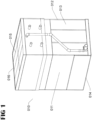
- an evaporative indirect heat exchanger product apparatus generally designated by 010 is shown not forming part of the invention as claimed.
- the apparatus has four vertical sides that include a connection end 013, an opposite to connection end 016, an air inlet end 012, and an opposite to air inlet end 011.
- the apparatus also has a bottom end 014 and a top air discharge end 016.
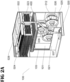
- Evaporative indirect heat exchanger product apparatus 100 is shown with spray pump 020, fan motor 025, fan 026, fan casing panel 012, water collection system 400, indirect serpentine tube heat exchangers 023, spray water distribution system 022, mist eliminators 028, spray water nozzles 024, rear water collection support 103, inspection door 101, and spray water sump 021.
- area 036 in the vicinity of fan 026 and fan motor 025 below water collection system 400 is denoted as the dry area 036, while the area to the left and below water collector system 400 is denoted as wet area 037.
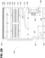
- Hot process fluid may enter indirect heat exchanger 023 from top inlet connection(s) 029 to be distributed through top heat exchanger header 030 through serpentine tube circuits 033 to be collected by bottom header exchanger header 032 to leave cooled process fluid exiting through bottom outlet connection(s) 031.
- Process fluid is indirectly cooled from air forced through heat exchanger by fan 026 and cooled water collected from sump 021 by pump 020 to be distributed to top of heat exchanger through piping 022 and spray nozzles 024.
- a mist eliminator section 028 is typically installed above spray nozzles 024 to remove water from the air discharge.
- example 100 is an evaporative indirect heat exchanger product which could be a closed circuit cooling tower or an evaporative condenser, with an overlapping gutter water collection system 400. Note that overlapping gutter water collection system 400 does not span the full footprint of the example such that a portion of the air goes through overlapping gutter water collection system 400 and some of the air freely bypasses around it.
- the length X2 of overlapping gutter water collection system and width X3 of sump 021 in the present example would allow for a minimum distance, X4 - X5 of 61 cm (24 inches) for maintenance access to dry area 036 via an optional door 101 as shown in Figure 2A .
- the overlapping gutter water system 400 extends from the fan inlet end 012 and shadows or overhangs part of the sump 021, such that distance X2 is greater than distance X4.
- Distance X2 - X4 or X3 - X1 is greater than 0 cm (0 inch) and ideally greater than 13 cm (5 inches) to assure that virtually no water reaches dry area 036, including times when the fan 026 is rotating slowly or is not operating.
- the overlapping gutter water system 400 is sloped such that water freely flows towards and cascades into sump 021 under the effect of gravity.
- the slope of overlapping gutter water system 400 defined by angle ⁇ 1, is typically greater than 0° and less than 80°, with optimal angle ⁇ 1 between 1° and 5°.
- evaporative cooling equipment is in forced draft, single-singled air inlet configuration but it is not a limitation of the invention.
- Many Figures are shown with unhoused centrifugal fan 026 forcing or pushing air through the unit, the actual fan system may be any style fan system that moves air through the unit including but not limited to forced draft in a generally counterflow, crossflow or parallel flow with respect to the spray. It should be understood that fan location and the direction of the air intake and discharge could be optimized, and are not a limitation to the examples and embodiments presented.
- motor 025 may be directly connected to the fan 026 as shown, be belt drive, or gear drive.
- the invention also concerns double-sided air inlet, triple-sided air inlet, and quadruple-sided air inlet forced draft evaporative cooling equipment, as well as single-sided air inlet, double-sided air inlet, triple-sided air inlet, and quadruple-sided air inlet induced draft evaporative cooling equipment.
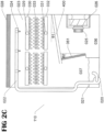
- Example 110 describes an alternative arrangement to that of the first example 100 shown in Figures 2A and 2B , with louvers 061 separating dry region 036 and wet region 037.
- the use of louvers 061 in the opening between sump 021 and overlapping gutter water system 400 assures that virtually no water will reach dry area 036 surrounding motor 025 and fan 026, ensuring a clean and safe environment around the fans for easy access and maintenance.
- Angle ⁇ 2 between overlapping gutter water system 400 and louvers 061 is typically less than 90° + ⁇ 1, to assure that virtually no water can get to dry area 036 through the louvers 061 which is especially important when fan 026 is either rotating very slowly or not at all while spray pump 020 is in operation.
- third example 050 not forming part of the invention as claimed is an open cooling tower with a direct heat exchanger section 052, which usually is comprised of fill sheets.
- Figure 2D has similar components numbered the same as Figure 2B .
- Water collection system 400 in accordance with the third example of the present invention operates exactly as was discussed in Figure 2B except for the heat exchanger is now a direct evaporative heat exchanger 052.
- Water to be cooled enters water distribution 053 and is sprayed from spray water pipe 022 from nozzles 024 onto direct heat exchanger 052.
- cooled process water exists the open cooling tower 050 from exit connection 054.
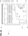
- example 200 is an evaporative indirect heat exchanger product which could be a closed circuit cooling tower or an evaporative condenser, with an overlapping gutter water collection system 400.
- Gutter assemblies of overlapping gutter water system 400 of example 200 are similar to that of previous examples and embodiments.
- the overlapping gutter water system 400 only extends through part of the footprint of the unit. The water collected by the gutter assemblies of the overlapping gutter water system 400 is funneled to a water collection trough 201, from which it will drain to the sump 021 under the effect of gravity, via a drain 202.
- overlapping gutter water system 400 design, and sump 021 width can be adjusted to optimize the ratio between dry region 036 and wet region 037.
- size and of the water collection trough 201, as well as the length and nature of the drain 202 and the width and depth of the sump 021, are not a limitation of the present example.
- FIG. 3B A fifth example not forming part of the invention as claimed is shown in Figure 3B .
- the fifth embodiment 210 describes an alternative arrangement to that of the fourth example 200 shown in Figure 3A , with added louvers 061 now separating dry region 036 from wet region 037.
- the use of louvers 061 assures that virtually no water will reach the dry area surrounding the motor 025 and fan 026, ensuring a clean and safe environment around the fans for easy access and maintenance.
- size of the water collection trough 201, as well as the length and nature of the drain 202, the type and size of the louvers 061 and the width and depth of the sump 021 are not a limitation of the present example.
- overlapping gutter water system 400 design, and sump 021 width can be adjusted to optimize the ratio between dry region 036 and wet region 037.
- example 500 is an evaporative indirect heat exchanger product which could be a closed circuit cooling tower or an evaporative condenser, with an overlapping water gutter system 501,. It should be noted that in this example, all of the air flowing through indirect heat exchangers 023 first goes through overlapping gutter water gutter system 501. Gutter assemblies of overlapping gutter water gutter system 501 of example 500 could be similar to that of previous examples but now span the full footprint of example 500.
- the overlapping gutter water gutter system 501 extends almost through the entire unit, resulting in dry area 036 which is now the entire volume underneath overlapping gutter water gutter system 501.
- the water collected by the overlapping gutter water gutter system 501 is funneled to a water collection trough 502, from which it drains to the sump 021 under the effect of gravity, via a drain 503.
- Angle ⁇ 1 of the overlapping gutter water collection system 501 is typically greater than 0° and less than 80°, with optimal angle between 1° and 5°. It should be understood that the size and shape of the water collection trough 502, as well as the length and nature of the drain 503, and the width and depth of the sump 021, are not a limitation of the present example.
- a seventh example not forming part of the invention as claimed is shown in Figure 4B .
- the seventh example 510 describes an alternative arrangement to that of the sixth example 500, in which the sump 021 can be inspected while the fan 026 and spray pump 020 are in operation.
- Gutter assemblies of overlapping gutter water gutter system 501 of example 510 could be similar to that of previous examples.
- Solid panel 511 is used to isolate sump 021 and associated make-up and sump heater devices (not shown) from the air stream.
- Solid panel 511 is designed to accommodate drain 503 connecting the water collection trough 502 to the sump 021. Accessibility to the sump 021 from the outside of the unit is made possible by the presence of access door 512 or optionally, solid panel 511 could be made removable.
- Angle ⁇ 1 of the overlapping gutter water collection system 501 is typically greater than 0° and less than 80°, with optimal angle between 1° and 5°. It should be understood that the size and of the water collection trough 502, as well as the length and nature of the drain 503, the width and depth of the sump 021, the shape and size of the solid panel 511, and the shape, size and location of the access door 512 are not a limitation of the present example.
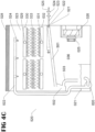
- the eighth example 520 describes an alternative arrangement to that of the sixth or seventh examples in which overlapping gutter water gutter system 501 is equipped with a cleaning system 521, to prevent clogging of the gutters.
- the cleaning system is composed of a nozzle 522, water supply line 523, control valve 524 and connection to a water supply 525.
- Cleaning water can be water from the network, spray water from the sump, make-up water, recycled or any clean available pressurized water supply.
- the cleaning water source is not a limitation of the example.
- gutter cleaning system 521 can be added to all disclosed examples. Gutter assemblies of overlapping gutter water gutter system 521 of example 520 could be similar to that of previous examples.
- Angle ⁇ 1 of the overlapping gutter water collection system 501 is typically greater than 0° and less than 80°, with optimal angle between 1° and 5°.
- the size of the water collection trough 502, as well as the length and nature of the drain 503, and the width and depth of the sump 021, are not a limitation of the present example.
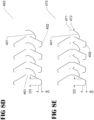
- Ninth example 530 describes an alternative arrangement to that of the sixth example 500, in which the air is induced through the evaporative heat rejection equipment through inlet louvers 531 by the fan 026 driven by motor 025.
- Gutter assemblies of overlapping water gutter system 501 of embodiment 530 could be similar to that of previous examples.
- the overlapping water gutter system 501 extends almost through the entire unit, resulting in dry area 036 which is now the entire volume underneath overlapping gutter water gutter system 501.
- the water collected by the overlapping gutter water gutter system 501 is directed to water collection trough 532, from which it drains to sump 021 under the effect of gravity, via drain 533.
- Angle ⁇ 1 of the overlapping gutter water collection system 501 is typically greater than 0° and less than 80°, with the optimal angle between 1° and 5°. It should be understood that the size and of the water collection trough 532, as well as the length and nature of the drain 533, the width and depth of the sump 021, the shape and size of the solid panel 511, and the shape, size and location of the inlet louvers 531 are not a limitation of the present example. A tenth example not forming part of the invention as claimed is shown in Figure 5A . Similar components have similar numerals as per Figure 2B in Figures 5A and 5B .
- Figure 5A shows a backside view, through the blank-off face 011 (defined in Figure 1 ) of example 540, which is an evaporative indirect heat exchanger product which could be a closed circuit cooling tower or an evaporative condenser, with an overlapping water gutter system 541.
- Gutter assemblies of overlapping water gutter system 541 of example 540 could be similar to that of previous examples.
- the overlapping gutter assemblies 542 of the water collection system 541 of example 540 are sloped towards the center of the example 540 where angle ⁇ 1 of the overlapping gutter water collection system 542 is typically greater than 0° and less than 80°, with optimal angle between 1° and 5°, so as to direct the water towards a central water collection trough 543, from which the water drops by gravity to sump 021 via drain 544.
- Water collection system 541 may optionally extend through only part of the footprint of example 540 as shown in Figures 2A , 2B , 2C , 2D , 3A and 3B creating wet and dry regions 037 and 036 respectively as presented in those Figures.
- Water collection system 541 may also optionally extend the full footprint where all the air must pass through overlapping gutter assemblies 542 as shown in Figures 4A , 4B , 4C and 4D thus creating dry area 036 below overlapping gutter assemblies 542. It should be understood that the angle and length of the overlapping gutter water gutter system 541, the size and of the water collection trough 543, as well as the length and nature of the drain 544, and the width and depth of the sump 021, are not a limitation of the present example.
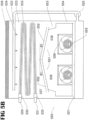
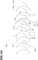
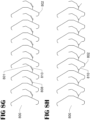
- FIG. 5B An eleventh example 550 not forming part of the invention as claimed is shown in Figure 5B describing another way to optimize airflow and water management, with an overlapping gutter water gutter system 551.
- Gutter assemblies of overlapping gutter water gutter system 551 of example 550 could be similar to that of previous examples.
- the overlapping gutter assemblies 552 of the water collection system 551 of example 550 are sloped towards the sides of the unit, and angle ⁇ 1 of the overlapping gutter water collection system 541 is typically greater than 0° and less than 80°, with optimal angle between 1° and 5° so as to direct the water towards lateral central water collection troughs 553 from which the water circulates to the sump 021 via a drain 554.
- Water collection system 551 may optionally extend through only part of the footprint of example 550 as shown in Figures 2A , 2B , 2C , 2D , 3A and 3B creating wet and dry regions 037 and 036 respectively as presented in those Figures. Water collection system 551 may also optionally extend the full footprint where all the air must pass through overlapping gutter assemblies 552 as shown in Figures 4A , 4B , 4C and 4D thus creating dry area 036 below overlapping gutter assemblies 552. It should be understood that the angle and length of the overlapping gutter water gutter system 551, the size of the water collection trough 553, as well as the length and nature of the drain 554, and the width and depth of the sump 021, are not a limitation of the present example.
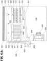
- a first embodiment 600 of the present invention is shown in Figure 6A describing an arrangement where the spray water caught by overlapping gutter water gutter system 501 drains into sump 606 and note that sump 606 is mounted above fan 026 and fan motor 025. The majority of sump 606 is also mounted outside the footprint of embodiment 600 making serviceability much safer and easier, even while fan 026 and motor 025 of embodiment 600 is in operation. Notice that spray pump 020 is mounting in the portion of sump 606 which is external from the footprint of embodiment 600 which allows for safe inspection and servicing of sump 606, spray pump 020, make-up assembly (not shown), sump strainer (not shown), and sump heater (not shown) through removable inspection door 602 even while fan 026 is in full operation.
- Removable access door 602 may also be attached via optional hinge assembly 604.
- Baffle plate 608 insures that air flowing does not leak past the water level preventing water from blowing out sump 606 when being serviced.
- Another additional benefit of mounting sump 606 and spray pump 020 higher than fan 026 is reduced pumping requirements compared to other examples and prior art where the sump and spray pump are mounted at the lowest part of the equipment thus requiring less head to overcome and reducing the power required to run spray pump 020.
- Angle ⁇ 1 of the overlapping gutter water collection system 501 is typically greater than 0° and less than 80°, with optimal angle between 1° and 5°. It should be understood that the width and size of sump 606 is not a limitation of the present example.
- evaporative indirect heat exchanger 023 may be of the serpentine tube type or may also be of plate coil type 609 as shown and the type of indirect heat exchanger is not a limitation of the invention. In addition any style evaporative heat exchanger falls within the scope of this invention. It should be noted that dry area 036 exists under the entire overlapping gutter water gutter system 501 which leaves plenty of room for serviceability and there can optionally be a service door entering the structure (not shown).
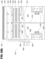
- FIG. 6B A second embodiment 610 according to the present invention is shown in Figure 6B , which is identical to embodiment 600 in Figure 6A except for embodiment 610 has two fans 026, two motors 025 and divider wall 612.
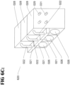
- embodiment 620 in Figure 6C , a modular construction of three embodiments 600 from Figure 6A installed together making field assembly, serviceability and control of various parameters much easier.
- embodiment 620 employs three separate heat exchange units such that there are three fans 026, three sumps 021, three spray water distribution pipes 022, three sets of mist eliminators 028 and three evaporative heat exchangers (not shown).
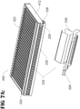
- Overlapping gutter water collection system 400 is shown to be comprised of a plurality of four-piece gutter assemblies 232 which can be constructed of sheet metal, plastic or any formable material and can even be printed.
- Front top frame 224 doubles as an air and water baffle which contains the water and air as desired.
- Rear frame 222 has comb-like drip edges to allow for good alignment and also funnels the caught spray water to the primary channels (shown in a later figure).
- Oversized gutter 228 is designed to catch excess spray water against the end of the overlapping gutter water collection system 400.
- Louver channel 226 has an integrated drip edge to keep water on the wet side of overlapping gutter water collection system 400.
- Louver channel extension 230 also has an integrated drip edge to keep water contained on the wet side of overlapping gutter water collection system 400.
- Welded end cap 236 allows for proper sealing against the unit wall to prevent water from leaking down the side wall of the unit.
- this gutter design can either be a multipart design that needs to be assembled by rivets, glue or by welding or it could be a single-piece extrusion, injection molded part or even 3D printed and the method of assembly or manufacture is not a limitation of the invention. Further, the parts may be made of common materials such as sheet metal or plastics and the type of material used is not a limitation of the invention.
- FIG. 7B a perspective bottom view of overlapping gutter water collection system 400 is in accordance with the twelfth example.
- Overlapping gutter water collection system 400 is shown which can be constructed of sheet metal, plastic or any formable material and can even be printed.
- Front top frame 224 doubles as an air and water baffle which contains the water and air as desired.
- Louver channel 226 has an integrated drip edge to keep water on the wet side of overlapping gutter water collection system 400.
- Louver water diverter with channel extension 230 also has an integrated drip edge to keep water contained on the wet side of overlapping gutter water collection system 400.
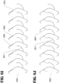
- a thirteenth example that is not independently claimed is water collection system 400 shown in Figure 8A and is designed to collect the spray water flowing from the top side, while letting air flow generally vertically through from the bottom side.
- Primary water collection channel 401 collects most of the spray water.
- Secondary water collection channel 402 catches any remaining spray which can be especially prevalent from either splashing, when air velocity is low, when there is no air is flowing through water collection system 400 or during extremely heavy water loading periods.
- Deflection plate 403 and top drip edge 404 force spray water to primary water collection channel 401.
- the length, angles, position and shape of the top drip edge 404 are designed to balance water collection performance and limit airside pressure drop through the overlapping gutter water collection system 400.
- Dimension D1 is typically between 1.3 cm (0.5 inch) and 30 cm (12 inches).
- Dimension D2 is typically between 1.3 cm (0.5 inch) and 30 cm (12 inches).
- Dimension D3 is typically between 1.3 cm (0.5 inch) and 20 cm (8 inches).
- Dimension D4 is typically between 1.3 cm (0.5 inch) and 20 cm (8 inches).
- Dimension D5 is typically between 13 cm (5 inches) and 76 cm (30 inches).
- Dimension D6 is typically between 10 cm (4 inches) and 51 cm (20 inches).
- Dimension D7 is typically between 10 cm (4 inches) and 51 cm (20 inches).
- Dimension D8 is greater than 0 cm (0 inch) to ensure proper drainage of water from top drip edge 404 to primary water collection channel 401.
- Dimension D9 is greater than 0 cm (0 inch).
- dimensions D1 and D2 can be changed to optimize the water collection capacity of the primary water collection channel 401, as well as to ensure non-clogging, and allow for easy inspection and cleaning.
- dimensions D3 and D4 can be changed to optimize the water collection capacity of the secondary water collection channel 402, as well as to ensure non-clogging, and allow for easy inspection and cleaning.
- the decision on how to define dimensions D5, D6, D7, and D8 is a balance between the acceptable airside pressure drop through the overlapping gutter water collection system 400, the difficulty in degree of manufacturing, and allowable cost and weight of the overlapping gutter water collection system 400.
- the water collection gutters are installed at an angle to increase water velocity, allow for drainage, and for self-cleaning.
- the air passages are designed to minimize airside pressure drop while assuring excellent water collection performance.
- example 410 is shown in Figure 8B with an oversized water collection channel 411 which is attached to the evaporative heat transfer equipment side wall 412.
- the air entering generally vertically through the bottom of water collection system 410 exists at the top at a non-vertical direction imposed by the angle ⁇ 3 of deflection plate 403. This non-vertical air stream deflects some of the spray water towards the unit side wall 412 which can result in an uneven water loading over the water collection system 410.
- oversized water collection channel 411 only at side wall 412, provides increased water collection capability thus helping counteract the increased spray water flow rate on one side of the equipment.
- Width D10 and height D11 of the oversized water collection channel 411, and gutter overlap distance D8 are designed to balance the water collection performance and limit the airside pressure drop through the overlapping gutter water collection system 410 and are not a limitation of this example.
- overlapping gutter water collection system 450 is shown with added drip edges 451 to the primary water collection channel 401 to improve water catching performance. Drip edges 451 will be most useful for during high water loading or low air flow situations. The addition of drip edges 451 may increase airside pressure drop. All key dimensions discussed in Figure 8A can be optimized based on required water loading and airside pressure drop requirements. The length, angle, position and shape of drip edges 451 can be designed to balance the water collection performance and limit the airside pressure drop through the overlapping gutter water collection system 450.
- a sixteenth example 460 that is not independently claimed and a seventeenth example 470 that is not independently claimed are shown in Figures 8D and 8E respectively.
- holes or slots 461 and 471 respectively are added to the design to allow for water to flow from primary channel 401 to secondary water collection channel 402.
- the optimal hole or slot size and interval is a function of channel size, water flow rate and air flow rate.
- secondary water collection channel 402 volume could be increased by increasing both channel depth D4 and width D3.
- eighteenth example 480 that is not independently claimed includes tertiary water collection channel 481 to increase the total water collection volume of each gutter.
- the size of the primary water collection channel 482 and secondary water collection channel 483 can be decreased to increase airflow through the water collection system 480 while keeping the water collection volume equal to that the water collection system not employing the tertiary water collection channel 481.
- FIGs 8G and 8H nineteenth example 800 that is not independently claimed is shown with integral dampers 810 in the open and closed positons, respectively.
- Damper 810 is forced in the open (up) position when sufficient airflow is flowing through water collection system 800 and closes by gravity when the fan is off.
- Integral dampers 810 may also be motorized (not shown).
- Integral dampers 810 are affixed to primary water channel 801 via hinge 808. Dampers 810, when closed, will prevent water splash-out during extremely low fan speeds and also when the fan is off, by deflecting spray water toward the secondary water collection channel 802.
- Integral dampers 810 when closed during subfreezing temperatures, help prevent ice formation and help to keep the indirect heat exchanger from freezing as well by preventing natural airflow when the fan is off. Integral dampers 810 could be part an integral part of the design with mounting holes as part of the gutter design, could be an add-on, could be mounted to the end caps (as defined in Figure 7A , part 236), or as a stand-alone module and is not a limitation of the invention.
- a twentieth example 850 that is not independently claimed is shown with integral dampers 860 in the open and closed positons, respectively.
- damper 860 is forced in the open (up) position when sufficient airflow is flowing through water collection system 850 and closes by gravity when the fan is off.
- Integral dampers 860 may also be motorized (not shown).
- Integral dampers 860 are affixed to deflection plate 853 via hinge 858. Dampers 860, when closed, will prevent water splash-out during extremely low fan speeds and also when the fan is off, by deflecting spray water toward the primary water collection channel 851.
- Integral dampers 860 when closed during subfreezing temperatures, help prevent ice formation and help to keep the indirect heat exchanger from freezing as well by preventing natural airflow when the fan is off. Integral dampers 860 could be part an integral part of the design with mounting holes as part of the gutter design, could be an add-on, could be mounted to the end caps (as defined in Figure 7A , part 236), or as a stand-alone module and is not a limitation of the invention.
Landscapes
- Engineering & Computer Science (AREA)
- Mechanical Engineering (AREA)
- General Engineering & Computer Science (AREA)
- Physics & Mathematics (AREA)
- Thermal Sciences (AREA)
- Heat-Exchange Devices With Radiators And Conduit Assemblies (AREA)
Applications Claiming Priority (2)
| Application Number | Priority Date | Filing Date | Title |
|---|---|---|---|
| US15/692,585 US10677543B2 (en) | 2017-08-31 | 2017-08-31 | Cooling tower |
| PCT/US2018/048086 WO2019046160A1 (en) | 2017-08-31 | 2018-08-27 | WATER COLLECTOR ARRANGEMENT |
Publications (4)
| Publication Number | Publication Date |
|---|---|
| EP3676556A1 EP3676556A1 (en) | 2020-07-08 |
| EP3676556A4 EP3676556A4 (en) | 2021-04-28 |
| EP3676556C0 EP3676556C0 (en) | 2023-11-22 |
| EP3676556B1 true EP3676556B1 (en) | 2023-11-22 |
Family
ID=65435015
Family Applications (1)
| Application Number | Title | Priority Date | Filing Date |
|---|---|---|---|
| EP18850404.7A Active EP3676556B1 (en) | 2017-08-31 | 2018-08-27 | Water collection arrangement |
Country Status (12)
| Country | Link |
|---|---|
| US (2) | US10677543B2 (enExample) |
| EP (1) | EP3676556B1 (enExample) |
| JP (1) | JP7292262B2 (enExample) |
| CN (2) | CN111164368B (enExample) |
| AU (1) | AU2018324521B2 (enExample) |
| BR (1) | BR112020003882B1 (enExample) |
| CA (1) | CA3073945A1 (enExample) |
| ES (1) | ES2964884T3 (enExample) |
| MX (1) | MX2020002318A (enExample) |
| SG (1) | SG11202001746TA (enExample) |
| WO (1) | WO2019046160A1 (enExample) |
| ZA (1) | ZA202001293B (enExample) |
Families Citing this family (19)
| Publication number | Priority date | Publication date | Assignee | Title |
|---|---|---|---|---|
| WO2013134245A1 (en) * | 2012-03-06 | 2013-09-12 | Mestek , Inc. | Evaporative cooling system and device |
| US10775117B2 (en) | 2016-09-30 | 2020-09-15 | Baltimore Aircoil Company | Water collection/deflection arrangements |
| US11844541B2 (en) * | 2017-02-03 | 2023-12-19 | Aggreko, Llc | Cooling tower |
| US10677543B2 (en) | 2017-08-31 | 2020-06-09 | Baltimore Aircoil Company, Inc. | Cooling tower |
| CN113614482A (zh) | 2019-03-19 | 2021-11-05 | 巴尔的摩汽圈公司 | 具有羽流消减组件旁路的热交换器 |
| AU2020401287A1 (en) | 2019-12-11 | 2022-06-23 | Baltimore Aircoil Company, Inc. | Heat exchanger system with machine-learning based optimization |
| CN111060281B (zh) * | 2019-12-24 | 2024-08-20 | 上海金日冷却设备有限公司 | 一种冷却塔收水器阻力测试装置及其测试方法 |
| US11609051B2 (en) | 2020-04-13 | 2023-03-21 | Harold D. Revocable Trust | Apparatus for cooling liquid and collection assembly therefor |
| EP4150428A4 (en) | 2020-05-12 | 2024-05-08 | Baltimore Aircoil Company, Inc. | COOLING TOWER CONTROL SYSTEM |
| CN111450633A (zh) * | 2020-05-14 | 2020-07-28 | 中钢集团马鞍山矿山研究总院股份有限公司 | 一种矿井排风的余热回收和气体净化组合装置 |
| CN111928541A (zh) * | 2020-06-24 | 2020-11-13 | 吉林省冰轮制冷工程有限公司 | 一种风冷制冷机组冷凝器用喷淋机构 |
| CN112227779B (zh) * | 2020-09-29 | 2024-06-28 | 中国电力工程顾问集团西南电力设计院有限公司 | 一种高位塔与循环水泵房集成一体化的布置结构 |
| US11976882B2 (en) | 2020-11-23 | 2024-05-07 | Baltimore Aircoil Company, Inc. | Heat rejection apparatus, plume abatement system, and method |
| CN113776351B (zh) * | 2021-08-23 | 2023-12-29 | 中广核工程有限公司 | 鼓风式通风冷却塔及冷却塔排布系统 |
| WO2024076765A2 (en) * | 2022-10-07 | 2024-04-11 | Baltimore Aircoil Company, Inc. | Liquid collector |
| CN115682472B (zh) * | 2022-11-01 | 2024-09-24 | 浙江宝丰科技股份有限公司 | 一种蒸发式冷凝器 |
| CN116336701B (zh) * | 2023-05-25 | 2023-07-28 | 山东大华环境节能科技有限公司 | 一种多级换热的蒸发式冷凝器 |
| CN116678237B (zh) * | 2023-07-10 | 2023-11-28 | 无锡市科巨机械制造有限公司 | 一种可循环使用壳程冷却水的闭式冷却塔装置 |
| CN118654506B (zh) * | 2024-08-20 | 2024-10-15 | 江苏丰泰节能环保科技有限公司 | 一种具有除雾防护机构的闭式冷却塔 |
Family Cites Families (39)
| Publication number | Priority date | Publication date | Assignee | Title |
|---|---|---|---|---|
| US2311155A (en) * | 1938-03-26 | 1943-02-16 | Clifford H Carr | Heat exchange apparatus |
| US2431389A (en) * | 1945-09-25 | 1947-11-25 | Walter L Fleisher | Apparatus for humidifying and cleaning gaseous fluids such as air |
| US2775310A (en) * | 1953-06-01 | 1956-12-25 | Jack F Shelton | Cooling tower |
| FR1351499A (fr) * | 1962-12-20 | 1964-02-07 | Perfectionnements aux appareils refroidisseurs de liquide | |
| US3384165A (en) * | 1966-02-03 | 1968-05-21 | Du Pont | Heat exchanger |
| US3784171A (en) | 1968-02-16 | 1974-01-08 | Baltimore Aircoil Co Inc | Evaporative heat exchange apparatus |
| US3437319A (en) | 1968-05-20 | 1969-04-08 | Baltimore Aircoil Co Inc | Evaporative heat exchanger with airflow reversal baffle |
| US3572657A (en) | 1969-06-04 | 1971-03-30 | Baltimore Aircoil Co Inc | Water baffle |
| US4044078A (en) * | 1976-02-09 | 1977-08-23 | N.P.I. Corporation | Air handler |
| DE2619407B2 (de) * | 1976-05-03 | 1979-03-22 | Balcke-Duerr Ag, 4030 Ratingen | Rieseleinbau-Element für Kühltürme |
| US4218408A (en) * | 1976-05-03 | 1980-08-19 | Balcke-Durr Aktiengesellschaft | Cooling tower with ripple plates |
| DE7717599U1 (de) * | 1977-06-03 | 1977-11-17 | Regehr, Ulrich, Dr.-Ing., 5100 Aachen | Lamellendeflektor zur abscheidung von in einem fluessigkeit-dampf-gemisch mitgefuehrter fluessigkeit |
| US4196157A (en) * | 1978-07-06 | 1980-04-01 | Baltimore Aircoil Company, Inc. | Evaporative counterflow heat exchange |
| US4521350A (en) | 1984-01-16 | 1985-06-04 | The Munters Corporation | Drainage collection system |
| DE4119216C2 (de) * | 1991-06-11 | 1994-09-22 | Wurz Dieter | Tropfenabscheider |
| DE69225237T2 (de) * | 1991-11-27 | 1998-11-19 | Harold D Curtis | Modularer kühlturm |
| US5645770A (en) * | 1994-07-11 | 1997-07-08 | Koch Engineering Company, Inc. | Liquid collector-distributor device, system and method |
| US5545356A (en) | 1994-11-30 | 1996-08-13 | Tower Tech, Inc. | Industrial cooling tower |
| JP4062374B2 (ja) * | 1997-07-10 | 2008-03-19 | 株式会社前川製作所 | 製氷器 |
| US5958306A (en) * | 1997-10-16 | 1999-09-28 | Curtis; Harold D. | Pre-collectors for cooling towers |
| US6237900B1 (en) | 1999-03-08 | 2001-05-29 | Baltimore Aircoil Company, Inc. | Rigid evaporative heat exchangers |
| US6574980B1 (en) | 2000-09-22 | 2003-06-10 | Baltimore Aircoil Company, Inc. | Circuiting arrangement for a closed circuit cooling tower |
| JP4145255B2 (ja) * | 2004-02-02 | 2008-09-03 | 東京電力株式会社 | アンモニア冷凍装置 |
| WO2006063258A2 (en) * | 2004-12-10 | 2006-06-15 | Engineering Equipment & Service, Llc | Collector sump cooling tower |
| US7484718B2 (en) * | 2006-02-13 | 2009-02-03 | Baltimore Aircoil Company, Inc | Cooling tower with direct and indirect cooling sections |
| BRPI1006288A2 (pt) * | 2009-03-03 | 2016-04-19 | Harold Dean Curtis | resfriador de fluído de tiragem forçada direta, dispositivo de coleta de água e torre de resfriamento compacta |
| US20150330710A1 (en) * | 2009-03-03 | 2015-11-19 | Harold D. Curtis Revocable Trust | Direct Forced Draft Fluid Cooling Tower |
| US9273915B2 (en) | 2009-07-17 | 2016-03-01 | Amistco Seperation Products, Inc. | Enhanced capacity, reduced turbulence, trough-type liquid collector trays |
| US8585024B2 (en) | 2009-08-26 | 2013-11-19 | Aggreko, Llc | Cooling tower |
| KR101057338B1 (ko) | 2009-12-02 | 2011-08-17 | 로인테크(주) | 증발식 응축기 |
| US9091485B2 (en) * | 2010-09-15 | 2015-07-28 | Evapco, Inc. | Hybrid heat exchanger apparatus and method of operating the same |
| US9097465B2 (en) * | 2012-04-21 | 2015-08-04 | Lee Wa Wong | Air conditioning system with multiple-effect evaporative condenser |
| US9004463B2 (en) | 2012-12-17 | 2015-04-14 | Baltimore Aircoil Company, Inc. | Cooling tower with indirect heat exchanger |
| US9255739B2 (en) * | 2013-03-15 | 2016-02-09 | Baltimore Aircoil Company, Inc. | Cooling tower with indirect heat exchanger |
| US9897399B2 (en) * | 2013-11-12 | 2018-02-20 | Stellenbosch University | Water collection trough assembly |
| WO2015137956A1 (en) * | 2014-03-13 | 2015-09-17 | Schneider Electric It Corporation | Water collection system for indirect evaporative cooler |
| US10775117B2 (en) | 2016-09-30 | 2020-09-15 | Baltimore Aircoil Company | Water collection/deflection arrangements |
| US10852079B2 (en) * | 2017-07-24 | 2020-12-01 | Harold D. Curtis | Apparatus for cooling liquid and collection assembly therefor |
| US10677543B2 (en) | 2017-08-31 | 2020-06-09 | Baltimore Aircoil Company, Inc. | Cooling tower |
-
2017
- 2017-08-31 US US15/692,585 patent/US10677543B2/en active Active
-
2018
- 2018-08-27 EP EP18850404.7A patent/EP3676556B1/en active Active
- 2018-08-27 MX MX2020002318A patent/MX2020002318A/es unknown
- 2018-08-27 SG SG11202001746TA patent/SG11202001746TA/en unknown
- 2018-08-27 ES ES18850404T patent/ES2964884T3/es active Active
- 2018-08-27 CN CN201880063723.2A patent/CN111164368B/zh active Active
- 2018-08-27 WO PCT/US2018/048086 patent/WO2019046160A1/en not_active Ceased
- 2018-08-27 BR BR112020003882-2A patent/BR112020003882B1/pt active IP Right Grant
- 2018-08-27 CN CN202210367604.4A patent/CN114777524A/zh active Pending
- 2018-08-27 AU AU2018324521A patent/AU2018324521B2/en active Active
- 2018-08-27 JP JP2020512044A patent/JP7292262B2/ja active Active
- 2018-08-27 CA CA3073945A patent/CA3073945A1/en active Pending
-
2020
- 2020-02-28 ZA ZA2020/01293A patent/ZA202001293B/en unknown
- 2020-04-24 US US16/858,334 patent/US11248859B2/en active Active
Also Published As
| Publication number | Publication date |
|---|---|
| US11248859B2 (en) | 2022-02-15 |
| WO2019046160A1 (en) | 2019-03-07 |
| US20190063855A1 (en) | 2019-02-28 |
| CA3073945A1 (en) | 2019-03-07 |
| MX2020002318A (es) | 2020-10-05 |
| CN114777524A (zh) | 2022-07-22 |
| ZA202001293B (en) | 2023-06-28 |
| EP3676556A4 (en) | 2021-04-28 |
| US10677543B2 (en) | 2020-06-09 |
| SG11202001746TA (en) | 2020-03-30 |
| BR112020003882B1 (pt) | 2023-04-18 |
| CN111164368B (zh) | 2022-04-26 |
| EP3676556C0 (en) | 2023-11-22 |
| EP3676556A1 (en) | 2020-07-08 |
| AU2018324521B2 (en) | 2024-02-29 |
| JP7292262B2 (ja) | 2023-06-16 |
| BR112020003882A2 (pt) | 2020-09-24 |
| ES2964884T3 (es) | 2024-04-10 |
| US20200256629A1 (en) | 2020-08-13 |
| AU2018324521A1 (en) | 2020-03-12 |
| CN111164368A (zh) | 2020-05-15 |
| JP2020532702A (ja) | 2020-11-12 |
Similar Documents
| Publication | Publication Date | Title |
|---|---|---|
| US11248859B2 (en) | Water collection arrangement | |
| US11255620B2 (en) | Water collection/deflection arrangement | |
| US9562729B2 (en) | Direct forced draft fluid cooler/cooling tower and liquid collector therefor | |
| US4252752A (en) | Heat exchange unit in particular for an atmospheric heat exchanger | |
| EP1818640A2 (en) | Cooling tower with direct and indirect cooling sections | |
| KR101082791B1 (ko) | 하부급기형 냉각탑 | |
| CN101251340A (zh) | 冷却塔空气入口和排放盘 | |
| KR20110072825A (ko) | 3면 흡입식 냉각탑 | |
| KR101121174B1 (ko) | 향류형 냉각탑 | |
| US10852079B2 (en) | Apparatus for cooling liquid and collection assembly therefor | |
| US20230324134A1 (en) | Apparatus for cooling liquid and collection assembly therefor | |
| KR101952532B1 (ko) | 압입송풍형 냉각탑 | |
| KR100479838B1 (ko) | 실내용 냉각탑 | |
| KR101895937B1 (ko) | 압입송풍형 대향류냉각탑 | |
| RU2854049C1 (ru) | Адиабатическая система перераспределения с предварительным охлаждением | |
| JP7782845B2 (ja) | 冷却塔 | |
| RU2058003C1 (ru) | Охладитель воды | |
| KR200297204Y1 (ko) | 실내용 냉각탑 | |
| KR100328739B1 (ko) | 루버 내장형 냉각탑 | |
| CN119998612A (zh) | 液体收集器 |
Legal Events
| Date | Code | Title | Description |
|---|---|---|---|
| STAA | Information on the status of an ep patent application or granted ep patent |
Free format text: STATUS: THE INTERNATIONAL PUBLICATION HAS BEEN MADE |
|
| PUAI | Public reference made under article 153(3) epc to a published international application that has entered the european phase |
Free format text: ORIGINAL CODE: 0009012 |
|
| STAA | Information on the status of an ep patent application or granted ep patent |
Free format text: STATUS: REQUEST FOR EXAMINATION WAS MADE |
|
| 17P | Request for examination filed |
Effective date: 20200325 |
|
| AK | Designated contracting states |
Kind code of ref document: A1 Designated state(s): AL AT BE BG CH CY CZ DE DK EE ES FI FR GB GR HR HU IE IS IT LI LT LU LV MC MK MT NL NO PL PT RO RS SE SI SK SM TR |
|
| AX | Request for extension of the european patent |
Extension state: BA ME |
|
| DAV | Request for validation of the european patent (deleted) | ||
| DAX | Request for extension of the european patent (deleted) | ||
| A4 | Supplementary search report drawn up and despatched |
Effective date: 20210331 |
|
| RIC1 | Information provided on ipc code assigned before grant |
Ipc: F28F 25/04 20060101AFI20210325BHEP Ipc: E04H 5/12 20060101ALI20210325BHEP Ipc: F28C 1/00 20060101ALI20210325BHEP Ipc: F28C 1/14 20060101ALI20210325BHEP Ipc: F28F 25/00 20060101ALI20210325BHEP Ipc: F28F 25/02 20060101ALI20210325BHEP Ipc: F28F 25/08 20060101ALI20210325BHEP Ipc: F28D 1/04 20060101ALI20210325BHEP Ipc: F28D 1/047 20060101ALI20210325BHEP Ipc: F28D 1/053 20060101ALI20210325BHEP Ipc: F28D 5/02 20060101ALI20210325BHEP Ipc: F28F 25/06 20060101ALI20210325BHEP Ipc: F28F 25/12 20060101ALI20210325BHEP |
|
| GRAP | Despatch of communication of intention to grant a patent |
Free format text: ORIGINAL CODE: EPIDOSNIGR1 |
|
| STAA | Information on the status of an ep patent application or granted ep patent |
Free format text: STATUS: GRANT OF PATENT IS INTENDED |
|
| RIC1 | Information provided on ipc code assigned before grant |
Ipc: F28F 25/12 20060101ALI20230428BHEP Ipc: F28F 25/06 20060101ALI20230428BHEP Ipc: F28D 5/02 20060101ALI20230428BHEP Ipc: F28D 1/053 20060101ALI20230428BHEP Ipc: F28D 1/047 20060101ALI20230428BHEP Ipc: F28D 1/04 20060101ALI20230428BHEP Ipc: F28F 25/08 20060101ALI20230428BHEP Ipc: F28F 25/02 20060101ALI20230428BHEP Ipc: F28F 25/00 20060101ALI20230428BHEP Ipc: F28C 1/14 20060101ALI20230428BHEP Ipc: F28C 1/00 20060101ALI20230428BHEP Ipc: E04H 5/12 20060101ALI20230428BHEP Ipc: F28F 25/04 20060101AFI20230428BHEP |
|
| INTG | Intention to grant announced |
Effective date: 20230607 |
|
| GRAS | Grant fee paid |
Free format text: ORIGINAL CODE: EPIDOSNIGR3 |
|
| GRAA | (expected) grant |
Free format text: ORIGINAL CODE: 0009210 |
|
| STAA | Information on the status of an ep patent application or granted ep patent |
Free format text: STATUS: THE PATENT HAS BEEN GRANTED |
|
| AK | Designated contracting states |
Kind code of ref document: B1 Designated state(s): AL AT BE BG CH CY CZ DE DK EE ES FI FR GB GR HR HU IE IS IT LI LT LU LV MC MK MT NL NO PL PT RO RS SE SI SK SM TR |
|
| REG | Reference to a national code |
Ref country code: GB Ref legal event code: FG4D |
|
| REG | Reference to a national code |
Ref country code: CH Ref legal event code: EP Ref country code: DE Ref legal event code: R096 Ref document number: 602018061583 Country of ref document: DE |
|
| REG | Reference to a national code |
Ref country code: IE Ref legal event code: FG4D |
|
| U01 | Request for unitary effect filed |
Effective date: 20231122 |
|
| U07 | Unitary effect registered |
Designated state(s): AT BE BG DE DK EE FI FR IT LT LU LV MT NL PT SE SI Effective date: 20231127 |
|
| PG25 | Lapsed in a contracting state [announced via postgrant information from national office to epo] |
Ref country code: GR Free format text: LAPSE BECAUSE OF FAILURE TO SUBMIT A TRANSLATION OF THE DESCRIPTION OR TO PAY THE FEE WITHIN THE PRESCRIBED TIME-LIMIT Effective date: 20240223 |
|
| PG25 | Lapsed in a contracting state [announced via postgrant information from national office to epo] |
Ref country code: IS Free format text: LAPSE BECAUSE OF FAILURE TO SUBMIT A TRANSLATION OF THE DESCRIPTION OR TO PAY THE FEE WITHIN THE PRESCRIBED TIME-LIMIT Effective date: 20240322 |
|
| REG | Reference to a national code |
Ref country code: ES Ref legal event code: FG2A Ref document number: 2964884 Country of ref document: ES Kind code of ref document: T3 Effective date: 20240410 |
|
| PG25 | Lapsed in a contracting state [announced via postgrant information from national office to epo] |
Ref country code: IS Free format text: LAPSE BECAUSE OF FAILURE TO SUBMIT A TRANSLATION OF THE DESCRIPTION OR TO PAY THE FEE WITHIN THE PRESCRIBED TIME-LIMIT Effective date: 20240322 Ref country code: GR Free format text: LAPSE BECAUSE OF FAILURE TO SUBMIT A TRANSLATION OF THE DESCRIPTION OR TO PAY THE FEE WITHIN THE PRESCRIBED TIME-LIMIT Effective date: 20240223 |
|
| PG25 | Lapsed in a contracting state [announced via postgrant information from national office to epo] |
Ref country code: RS Free format text: LAPSE BECAUSE OF FAILURE TO SUBMIT A TRANSLATION OF THE DESCRIPTION OR TO PAY THE FEE WITHIN THE PRESCRIBED TIME-LIMIT Effective date: 20231122 Ref country code: PL Free format text: LAPSE BECAUSE OF FAILURE TO SUBMIT A TRANSLATION OF THE DESCRIPTION OR TO PAY THE FEE WITHIN THE PRESCRIBED TIME-LIMIT Effective date: 20231122 Ref country code: NO Free format text: LAPSE BECAUSE OF FAILURE TO SUBMIT A TRANSLATION OF THE DESCRIPTION OR TO PAY THE FEE WITHIN THE PRESCRIBED TIME-LIMIT Effective date: 20240222 Ref country code: HR Free format text: LAPSE BECAUSE OF FAILURE TO SUBMIT A TRANSLATION OF THE DESCRIPTION OR TO PAY THE FEE WITHIN THE PRESCRIBED TIME-LIMIT Effective date: 20231122 |
|
| PG25 | Lapsed in a contracting state [announced via postgrant information from national office to epo] |
Ref country code: CZ Free format text: LAPSE BECAUSE OF FAILURE TO SUBMIT A TRANSLATION OF THE DESCRIPTION OR TO PAY THE FEE WITHIN THE PRESCRIBED TIME-LIMIT Effective date: 20231122 |
|
| PG25 | Lapsed in a contracting state [announced via postgrant information from national office to epo] |
Ref country code: SK Free format text: LAPSE BECAUSE OF FAILURE TO SUBMIT A TRANSLATION OF THE DESCRIPTION OR TO PAY THE FEE WITHIN THE PRESCRIBED TIME-LIMIT Effective date: 20231122 |
|
| PG25 | Lapsed in a contracting state [announced via postgrant information from national office to epo] |
Ref country code: SM Free format text: LAPSE BECAUSE OF FAILURE TO SUBMIT A TRANSLATION OF THE DESCRIPTION OR TO PAY THE FEE WITHIN THE PRESCRIBED TIME-LIMIT Effective date: 20231122 Ref country code: SK Free format text: LAPSE BECAUSE OF FAILURE TO SUBMIT A TRANSLATION OF THE DESCRIPTION OR TO PAY THE FEE WITHIN THE PRESCRIBED TIME-LIMIT Effective date: 20231122 Ref country code: RO Free format text: LAPSE BECAUSE OF FAILURE TO SUBMIT A TRANSLATION OF THE DESCRIPTION OR TO PAY THE FEE WITHIN THE PRESCRIBED TIME-LIMIT Effective date: 20231122 Ref country code: CZ Free format text: LAPSE BECAUSE OF FAILURE TO SUBMIT A TRANSLATION OF THE DESCRIPTION OR TO PAY THE FEE WITHIN THE PRESCRIBED TIME-LIMIT Effective date: 20231122 |
|
| REG | Reference to a national code |
Ref country code: DE Ref legal event code: R097 Ref document number: 602018061583 Country of ref document: DE |
|
| U20 | Renewal fee for the european patent with unitary effect paid |
Year of fee payment: 7 Effective date: 20240723 |
|
| PLBE | No opposition filed within time limit |
Free format text: ORIGINAL CODE: 0009261 |
|
| STAA | Information on the status of an ep patent application or granted ep patent |
Free format text: STATUS: NO OPPOSITION FILED WITHIN TIME LIMIT |
|
| 26N | No opposition filed |
Effective date: 20240823 |
|
| REG | Reference to a national code |
Ref country code: CH Ref legal event code: PL |
|
| PG25 | Lapsed in a contracting state [announced via postgrant information from national office to epo] |
Ref country code: CH Free format text: LAPSE BECAUSE OF NON-PAYMENT OF DUE FEES Effective date: 20240831 Ref country code: MC Free format text: LAPSE BECAUSE OF FAILURE TO SUBMIT A TRANSLATION OF THE DESCRIPTION OR TO PAY THE FEE WITHIN THE PRESCRIBED TIME-LIMIT Effective date: 20231122 |
|
| PG25 | Lapsed in a contracting state [announced via postgrant information from national office to epo] |
Ref country code: IE Free format text: LAPSE BECAUSE OF NON-PAYMENT OF DUE FEES Effective date: 20240827 |
|
| U20 | Renewal fee for the european patent with unitary effect paid |
Year of fee payment: 8 Effective date: 20250723 |
|
| PGFP | Annual fee paid to national office [announced via postgrant information from national office to epo] |
Ref country code: ES Payment date: 20250901 Year of fee payment: 8 |
|
| PGFP | Annual fee paid to national office [announced via postgrant information from national office to epo] |
Ref country code: GB Payment date: 20250725 Year of fee payment: 8 |