EP3676546B1 - Verfahren und system zur herstellung von feststoffen - Google Patents
Verfahren und system zur herstellung von feststoffen Download PDFInfo
- Publication number
- EP3676546B1 EP3676546B1 EP18851112.5A EP18851112A EP3676546B1 EP 3676546 B1 EP3676546 B1 EP 3676546B1 EP 18851112 A EP18851112 A EP 18851112A EP 3676546 B1 EP3676546 B1 EP 3676546B1
- Authority
- EP
- European Patent Office
- Prior art keywords
- fluid
- coil
- flow
- solidified
- cold
- Prior art date
- Legal status (The legal status is an assumption and is not a legal conclusion. Google has not performed a legal analysis and makes no representation as to the accuracy of the status listed.)
- Active
Links
Images


Classifications
-
- F—MECHANICAL ENGINEERING; LIGHTING; HEATING; WEAPONS; BLASTING
- F25—REFRIGERATION OR COOLING; COMBINED HEATING AND REFRIGERATION SYSTEMS; HEAT PUMP SYSTEMS; MANUFACTURE OR STORAGE OF ICE; LIQUEFACTION SOLIDIFICATION OF GASES
- F25C—PRODUCING, WORKING OR HANDLING ICE
- F25C1/00—Producing ice
- F25C1/12—Producing ice by freezing water on cooled surfaces, e.g. to form slabs
-
- F—MECHANICAL ENGINEERING; LIGHTING; HEATING; WEAPONS; BLASTING
- F25—REFRIGERATION OR COOLING; COMBINED HEATING AND REFRIGERATION SYSTEMS; HEAT PUMP SYSTEMS; MANUFACTURE OR STORAGE OF ICE; LIQUEFACTION SOLIDIFICATION OF GASES
- F25C—PRODUCING, WORKING OR HANDLING ICE
- F25C1/00—Producing ice
-
- F—MECHANICAL ENGINEERING; LIGHTING; HEATING; WEAPONS; BLASTING
- F25—REFRIGERATION OR COOLING; COMBINED HEATING AND REFRIGERATION SYSTEMS; HEAT PUMP SYSTEMS; MANUFACTURE OR STORAGE OF ICE; LIQUEFACTION SOLIDIFICATION OF GASES
- F25C—PRODUCING, WORKING OR HANDLING ICE
- F25C1/00—Producing ice
- F25C1/12—Producing ice by freezing water on cooled surfaces, e.g. to form slabs
- F25C1/14—Producing ice by freezing water on cooled surfaces, e.g. to form slabs to form thin sheets which are removed by scraping or wedging, e.g. in the form of flakes
- F25C1/145—Producing ice by freezing water on cooled surfaces, e.g. to form slabs to form thin sheets which are removed by scraping or wedging, e.g. in the form of flakes from the inner walls of cooled bodies
- F25C1/147—Producing ice by freezing water on cooled surfaces, e.g. to form slabs to form thin sheets which are removed by scraping or wedging, e.g. in the form of flakes from the inner walls of cooled bodies by using augers
-
- F—MECHANICAL ENGINEERING; LIGHTING; HEATING; WEAPONS; BLASTING
- F25—REFRIGERATION OR COOLING; COMBINED HEATING AND REFRIGERATION SYSTEMS; HEAT PUMP SYSTEMS; MANUFACTURE OR STORAGE OF ICE; LIQUEFACTION SOLIDIFICATION OF GASES
- F25D—REFRIGERATORS; COLD ROOMS; ICE-BOXES; COOLING OR FREEZING APPARATUS NOT OTHERWISE PROVIDED FOR
- F25D17/00—Arrangements for circulating cooling fluids; Arrangements for circulating gas, e.g. air, within refrigerated spaces
- F25D17/02—Arrangements for circulating cooling fluids; Arrangements for circulating gas, e.g. air, within refrigerated spaces for circulating liquids, e.g. brine
-
- F—MECHANICAL ENGINEERING; LIGHTING; HEATING; WEAPONS; BLASTING
- F25—REFRIGERATION OR COOLING; COMBINED HEATING AND REFRIGERATION SYSTEMS; HEAT PUMP SYSTEMS; MANUFACTURE OR STORAGE OF ICE; LIQUEFACTION SOLIDIFICATION OF GASES
- F25D—REFRIGERATORS; COLD ROOMS; ICE-BOXES; COOLING OR FREEZING APPARATUS NOT OTHERWISE PROVIDED FOR
- F25D3/00—Devices using other cold materials; Devices using cold-storage bodies
- F25D3/005—Devices using other cold materials; Devices using cold-storage bodies combined with heat exchangers
-
- F—MECHANICAL ENGINEERING; LIGHTING; HEATING; WEAPONS; BLASTING
- F25—REFRIGERATION OR COOLING; COMBINED HEATING AND REFRIGERATION SYSTEMS; HEAT PUMP SYSTEMS; MANUFACTURE OR STORAGE OF ICE; LIQUEFACTION SOLIDIFICATION OF GASES
- F25C—PRODUCING, WORKING OR HANDLING ICE
- F25C2300/00—Special arrangements or features for producing, working or handling ice
-
- F—MECHANICAL ENGINEERING; LIGHTING; HEATING; WEAPONS; BLASTING
- F25—REFRIGERATION OR COOLING; COMBINED HEATING AND REFRIGERATION SYSTEMS; HEAT PUMP SYSTEMS; MANUFACTURE OR STORAGE OF ICE; LIQUEFACTION SOLIDIFICATION OF GASES
- F25C—PRODUCING, WORKING OR HANDLING ICE
- F25C2301/00—Special arrangements or features for producing ice
- F25C2301/002—Producing ice slurries
-
- F—MECHANICAL ENGINEERING; LIGHTING; HEATING; WEAPONS; BLASTING
- F25—REFRIGERATION OR COOLING; COMBINED HEATING AND REFRIGERATION SYSTEMS; HEAT PUMP SYSTEMS; MANUFACTURE OR STORAGE OF ICE; LIQUEFACTION SOLIDIFICATION OF GASES
- F25D—REFRIGERATORS; COLD ROOMS; ICE-BOXES; COOLING OR FREEZING APPARATUS NOT OTHERWISE PROVIDED FOR
- F25D2303/00—Details of devices using other cold materials; Details of devices using cold-storage bodies
- F25D2303/08—Devices using cold storage material, i.e. ice or other freezable liquid
- F25D2303/084—Position of the cold storage material in relationship to a product to be cooled
-
- F—MECHANICAL ENGINEERING; LIGHTING; HEATING; WEAPONS; BLASTING
- F25—REFRIGERATION OR COOLING; COMBINED HEATING AND REFRIGERATION SYSTEMS; HEAT PUMP SYSTEMS; MANUFACTURE OR STORAGE OF ICE; LIQUEFACTION SOLIDIFICATION OF GASES
- F25D—REFRIGERATORS; COLD ROOMS; ICE-BOXES; COOLING OR FREEZING APPARATUS NOT OTHERWISE PROVIDED FOR
- F25D2303/00—Details of devices using other cold materials; Details of devices using cold-storage bodies
- F25D2303/08—Devices using cold storage material, i.e. ice or other freezable liquid
- F25D2303/085—Compositions of cold storage materials
Definitions
- Different tool s and techniques may generally be utilized for solidification and/or solid production, such as ice production, drop forming, block freezing, flake freezing, and many other devices
- the first fluid includes a non-polar material and the second fluid includes a polar material.
- the first fluid includes at least hydrocarbon oil, aromatic oil, fluorinated oil, or silicone oil.
- the second fluid includes at least water, acidic acid, formic acid, carbocyclic acids, sulfuric acid, ethylene glycol, polyethylene glycol, tert-butyl, or DMSO.
- the first fluid includes a polar material and the second fluid includes a non-polar material.
- the first fluid includes at least water, alcohol, propylene glycol, ethylene glycol, DMSO, ammonia, or nitric acid.
- the second fluid includes at least fluorinated oil, cresol, high molecular weight silicon oil, high molecular weight hydrocarbon oil, high molecular weight paraffin, thermoset polymer, or metallic alloy.
- the first fluid includes water and the second fluid includes at least high-molecular weight paraffin or thermoset polymer, for example.
- contacting the first fluid with the second fluid includes entraining the second fluid within the first fluid.
- the first fluid includes aromatic oil and the second fluid includes water.
- Some embodiments further include cooling the first fluid before entraining the second fluid within the first fluid.
- the first fluid and the second fluid arc cooled simultaneously.
- entraining the second fluid within the first fluid includes flowing the first fluid and the second fluid through a coil to solidify at least a portion of the second fluid.
- one or more hydrodynamic properties of the first fluid form the second fluid into one or more solidified shapes.
- the one or more solidified shapes may be formed with at least a predictable size or a predictable shape.
- One or more features of the coil may control the one or more hydrodynamic properties of the first fluid that form the second fluid into the one or more solidified shapes formed with at least the predictable size or the predictable shape.
- the one or more features of the coil may include at least one or more diameters of the coil, one or more geometries of the coil, one or more interior structures of the coil, one or more orientations of the coil, or one or more lengths of the coil.
- the one or more features of the coil may include a change in orientation of the coil.
- the one or more features of the coil may include a change in diameter of the coil.
- entraining the second fluid within the first fluid includes introducing the second fluid as a parallel flow to the first fluid. In some embodiments, entraining the second fluid within the first fluid includes introducing the second fluid as a perpendicular flow to the first fluid.
- contacting the first fluid with the second fluid includes introducing the first fluid and the second fluid with respect to one or more cold surfaces, the first fluid may have an affinity for the one or more cold surfaces.
- Some disclosures include removing a solidified form of the second fluid from the one or more cold surfaces.
- the first fluid may coat at least a portion of the one or more cold surfaces and may interfere with the second fluid from adhering to the one or more cold surfaces.
- the first fluid includes hydrocarbon oil and the second fluid includes water.
- contacting the first fluid with the second fluid includes mixing the second fluid with the first fluid before introducing the first fluid and the second fluid with respect to the one or more cold surfaces. In some disclosures, contacting the first fluid with the second fluid includes separately introducing the first fluid and the second fluid with respect to the one or more cold surfaces.
- the one or more cold surfaces are comprised of a metal.
- Some embodiments may include other materials such as plastic, ceramic, and/or glass for the one or more cold surfaces.
- removing the solidified form of the second fluid from the one or more cold surfaces includes utilizing an auger to remove the solidified form of the second fluid from a cylindrically-shaped cold surface. In some disclosures. removing the solidified form of the second fluid from the one or more cold surfaces includes utilizing a rotating scrapper to remove the solidified form of the second fluid from a drum-shaped cold surface. In some disclosures, removing the solidified form of the second fluid from the one or more cold surfaces includes utilizing one or more linear scrappers to remove the solidified form of the second fluid from one or more planar cold surfaces
- Some disclosures include a solid production system that may include a first fluid and a second fluid, the first fluid and the second fluid may be immiscible with respect to each other.
- the system may include one or more surfaces configured to contact the first fluid and the second fluid with each other and to form one or more solids from the second fluid.
- the one or more surfaces are configured such that the first fluid and the second fluid are contacted with each other such that the second fluid is entrained within the first fluid.
- the one or more surfaces may include one or more coils configured to solidify at least a portion of the second fluid.
- the one or more surfaces include one or more cold surfaces such that the first fluid has an affinity for the one or more cold surfaces.
- Some disclosures include one or more solid removers configured to remove a solidified form of the second fluid from the one or more cold surfaces.
- the first fluid includes a non-polar material and the second fluid includes a polar material.
- the first fluid includes at least hydrocarbon oil, aromatic oil, fluorinated oil, or silicone oil.
- the second fluid includes at least water, acidic acid, formic acid, carbocyclic acids, sulfuric acid, ethylene glycol, polyethylene glycol, tert-butyl, or DMSO.
- the first fluid includes aromatic oil and the second fluid includes water.
- the first fluid includes hydrocarbon oil and the second fluid includes water.
- the first fluid includes a polar material and the second fluid includes a non-polar material.
- the first fluid includes at least water, alcohol, propylene glycol, ethylene glycol, DMSO, ammonia, or nitric acid.
- the second fluid includes at least fluorinated oil, cresol, high molecular weight silicon oil, high molecular weight hydrocarbon oil, high molecular weight paraffin, thermoset polymer, or metallic alloy.
- the first fluid includes water and the second fluid includes at least high-molecular weight paraffin or thermoset polymer.
- Some embodiments of the system include a heat exchanger positioned to cool the first fluid before entraining the second fluid within the first fluid.
- the first fluid and the second fluid are cooled simultaneously within the one or more coils.
- one or more hydrodynamic properties of the first fluid within the one or more coils form the second fluid into one or more solidified shapes.
- the one or more solidified shapes are formed with at least a predictable size or a predictable shape.
- one or more features of the coil control the one or more hydrodynamic properties of the first fluid that form the second fluid into the one or more solidified shapes formed with at least the predictable size or the predictable shape.
- the one or more features of the coil include at least one or more diameters of the coil, one or more geometries of the coil, one or more interior structures of the coil, one or more orientations of the coil, or one or more lengths of the coil. In some embodiments, the one or more features of the coil include a change in orientation of the coil. In some embodiments, the one or more features of the coil include a change in diameter of the coil.
- Embodiments of the system include a mixing nozzle configured to entrain the second fluid within the first fluid. Some embodiments include a tube positioned within the mixing nozzle such that the second fluid is introduced as a parallel flow to the first fluid. Some embodiments include a tube positioned within the mixing nozzle such that the second fluid is introduced as a perpendicular flow to the first fluid.
- the first fluid coats at least a portion of the one or more cold surfaces and interferes with the second fluid from adhering to the one or more cold surfaces.
- Some embodiments include a first storage container configured to hold the first fluid and a second storage container configured to hold the second fluid.
- Some disclosed systems include a combiner configured to combine the first fluid from the first storage container with the second fluid from the second storage container for delivery to the one or more cold surfaces.
- Systems may include a first conduit coupled with the first storage container and a second conduit coupled with the second storage container; the first conduit and the second conduit may be configured to deliver the first fluid and the second fluid separately to the one or more cold surfaces.
- the first conduit is coupled with the one or more solid removers to facilitate delivery of the first fluid to the one or more cold surfaces
- the one or more cold surfaces are comprised of a metal.
- Disclosed systems may include other materials such as plastic, ceramic, and/or glass for the one or more cold surfaces.
- the one or more solid removers configured to remove the solidified form of the second fluid from the one or more cold surfaces include an auger to remove the solidified form of the second fluid from a cylindrically-shaped cold surface.
- the one or more solid removers configured to remove the solidified form of the second fluid from the one or more cold surfaces include a rotating scrapper to remove the solidified form of the second fluid from a drum-shaped cold surface.
- the one or more solid removers configured to remove the solidified form of the second fluid from the one or more cold surface include one or more linear scrappers to remove the solidified form of the second fluid from one or more planar cold surfaces.
- Figures 1A - 1C , 2A , 2B and 4-17C show embodiments being useful for understanding the invention, which are outside the subject-matter of the claims.
- Figure 3 shows an embodiment according to the present invention, which discloses a method for a production of solids according to claim 1 and a system for a production of solids according to claim 7.
- This description provides embodiments, and is not intended to limit the scope, applicability or configuration of the disclosure. Rather, the ensuing description will provide those skilled in the art with an enabling description for implementing embodiments of the disclosure. Various changes may be made in the function and arrangement of elements.
- Some embodiments may provide for the creation of a solid with a high volumetric surface area, the amount of surface area per a given volume of material, using a machine and/ process that may involve minimal energy consumption, mechanical complexity, and/or heat transfer area.
- Some embodiments may include hydraulically forming the solid while simultaneously causing it to solidify via cooling.
- the hydraulic formation is controlled by the introduction of the two materials into a coil where the hydrodynamic properties of the entraining fluid (the first fluid) may cause the solidifying fluid (the second fluid) to automatically form shapes of a predictable size and/or shape.
- the hydrodynamic properties of the first fluid may be controlled by specific design features of the coil including, for example, its diameter, geometry, interior structure, length, and/or combination of different zones with changing features.
- the first fluid is a non-polar material and the second fluid is a polar material.
- the first fluid may include a hydrocarbon, aromatic, fluorinated, or silicone oil, where an example of the second fluid may include an immiscible polar fluid, such as water, acidic acid, formic acid or other carbocyclic acids, sulfuric acid, ethylene or polyethylene glycol, medium sized alcohols such as tert-butyl, or DMSO.
- the first fluid is a polar material and the second fluid is a non-polar material.
- the first fluid may include water, alcohol, propylene or ethylene glycol, DMSO, ammonia, or nitric acid
- the second fluid may include a fluorinated oil, cresol, a high molecular weight silicon oil, a high molecular weight hydrocarbon oil or paraffin, a thermoset polymer, or a metallic alloy.
- a coil assembly and various peripheral equipment are utilized for the coil to operate.
- Those peripherals include a pump for the first fluid, a mixing nozzle for both fluids, a heat exchanger for cooling the first fluid or the mixture, and/or containers for storing both the mixture, the first fluid, and the second fluid.
- Some embodiments may utilize a cold surface that may be protected by a first fluid.
- a second fluid may be allowed to come in near contact with the cold surface and solidify.
- the protection from the immiscible fluid may allow for the solid to be removed using a less or minimally complicated and/or low power mechanical device.
- the fluids used are immiscible, which may allow for them to physically and/or thermally contact each other throughout the process. Additionally, the first fluid may be chosen based on its affinity for the cold surface. If it has a higher affinity for the surface than the second fluid, surface tension effects may overpower buoyancy or mechanical forces and the cold surface may be protected.
- the first fluid may be an oil such as a hydrocarbon oil, an aromatic oil, or a silicone oil.
- the second fluid may be a polar fluid such as water or DMSO.
- the oil may preferentially cover the surface protecting it even under high hydrostatic or mechanical loading from the water, which may allow for high heat transfer between the water and cold surface but leaving the water poorly adhered to the cold surface so it may be removed with low power and mechanical complexity.
- Some embodiments may in general show fluid lines and heat exchangers as non-integral from any other pieces of process equipment.
- One skilled in the art generally knows that this may not always the case and may be depicted here for clarity. Additionally, not all the representations in these figures are illustrative and may not represent the geometric features of the coil; some may provide greater detail.
- System 100 may include a first fluid 104 and a second fluid 102; the first fluid 104 and the second fluid 102 may be immiscible with respect to each other.
- the system 100 may include one or more surfaces 109 configured to contact the first fluid 104 and the second fluid 102 with each other and to form one or more solids from the second fluid 102.
- the one or more surfaces 109 are configured such that the first fluid 104 and the second fluid 102 are contacted with each other such that the second fluid 102 is entrained within the first fluid 104.
- the one or more surfaces 109 may include one or more coils configured to solidify at least a portion of the second fluid 102.
- the one or more surfaces 109 include one or more cold surfaces such that the first fluid 104 has an affinity for the one or more cold surfaces.
- Some embodiments include one or more solid removers configured to remove a solidified form of the second fluid 102 from the one or more cold surfaces.
- the first fluid 104 includes a non-polar material and the second fluid 102 includes a polar material.
- the first fluid 104 includes at least hydrocarbon oil, aromatic oil, fluorinated oil, or silicone oil.
- the second fluid 102 includes at least water, acidic acid, formic acid, carbocyclic acids, sulfuric acid, ethylene glycol, polyethylene glycol, tert-butyl, or DMSO.
- the first fluid 104 includes aromatic oil and the second fluid 102 includes water.
- the first fluid 104 includes hydrocarbon oil and the second fluid 102 includes water.
- the first fluid 104 includes a polar material and the second fluid 102 includes a non-polar material.
- the first fluid 104 includes at least water, alcohol, propylene glycol, ethylene glycol, DMSO, ammonia, or nitric acid.
- the second fluid 102 includes at least fluorinated oil, cresol, high molecular weight silicon oil, high molecular weight hydrocarbon oil, high molecular weight paraffin, thermoset polymer, or metallic alloy.
- the first fluid 104 includes water and the second fluid 102 includes at least high-molecular weight paraffin or thermoset polymer.
- Some embodiments of the system 100 include a heat exchanger positioned to cool the first fluid 104 before entraining the second fluid 102 within the first fluid 104.
- the first fluid 104 and the second fluid 102 are cooled simultaneously within the one or more coils.
- one or more hydrodynamic properties of the first fluid 104 within the one or more coils form the second fluid 102 into one or more solidified shapes.
- the one or more solidified shapes are formed with at least a predictable size or a predictable shape.
- one or more features of the coil control the one or more hydrodynamic properties of the first fluid 104 that form the second fluid 102 into the one or more solidified shapes formed with at least the predictable size or the predictable shape.
- the one or more features of the coil include at least one or more diameters of the coil, one or more geometries of the coil, one or more interior structures of the coil, one or more orientations of the coil, or one or more lengths of the coil. In some embodiments, the one or more features of the coil include a change in orientation of the coil. In some embodiments, the one or more features of the coil include a change in diameter of the coil.
- Some embodiments of the system 100 include a mixing nozzle configured to entrain the second fluid 102 within the first fluid 104. Some embodiments include a tube positioned within the mixing nozzle such that the second fluid 102 is introduced as a parallel flow to the first fluid 104. Some embodiments include a tube positioned within the mixing nozzle such that the second fluid 102 is introduced as a perpendicular flow to the first fluid 104.
- the first fluid 104 coats at least a portion of the one or more cold surfaces and interferes with the second fluid 102 from adhering to the one or more cold surfaces.
- Some embodiments include a first storage container configured to hold the first fluid 104 and a second storage container configured to hold the second fluid 102.
- Some embodiments include a combiner configured to combine the first fluid 104 from the first storage container with the second fluid 102 from the second storage container for delivery to the one or more cold surfaces; the combiner may be an example of a mixing nozzle.
- Some embodiments include a first conduit coupled with the first storage container and a second conduit coupled with the second storage container; the first conduit and the second conduit may be configured to deliver the first fluid 104 and the second fluid 102 separately to the one or more cold surfaces.
- the first conduit is coupled with the one or more solid removers to facilitate delivery of the first fluid 104 to the one or more cold surfaces.
- the one or more cold surfaces are comprised of a metal. Some embodiments may include other materials such as plastic, ceramic, and/or glass for the one or more cold surfaces.
- the one or more solid removers configured to remove the solidified form of the second fluid 102 from the one or more cold surfaces include an auger to remove the solidified form of the second fluid 102 from a cylindrically-shaped cold surface.
- the one or more solid removers configured to remove the solidified form of the second fluid 102 from the one or more cold surfaces include a rotating scrapper to remove the solidified form of the second fluid 102 from a drum-shaped cold surface.
- the one or more solid removers configured to remove the solidified form of the second fluid 102 from the one or more cold surface include one or more linear scrappers to remove the solidified form of the second fluid 102 from one or more planar cold surfaces.
- System 100-a may be an example of system 100 of FIG. 1A .
- System 100-a may include a first fluid 104-a and a second fluid 102-a; the first fluid 104-a and the second fluid 102-a may be immiscible with respect to each other.
- the system 100-a may include one or more surfaces 109-a configured to contact the first fluid 104-a and the second fluid 102-a with each other and to form one or more solids from the second fluid 102-a.
- the one or more surfaces 109-a may be configured such that the first fluid 104-a and the second fluid 102-a are contacted with each other such that the second fluid 102-a is entrained within the first fluid 104-a.
- the one or more surfaces 109-a may include one or more coils configured to solidify at least a portion of the second fluid 102-a.
- the first fluid 104-a may be stored in a first fluid storage container 103 before being delivered to the one or more surfaces 109-a; similarly, the second fluid 102-a may be stored in a second fluid storage container 101 before being delivered to the one or more cold surfaces 109-a.
- the first fluid 104-a may be extracted from the first fluid storage container 103 and may be sent to the one or more surfaces 109-a that may be configured as an entraining or mixing assembly, which may be an example of the one or more surfaces 109 of FIG. 1A .
- the second fluid 102-a may be taken from the second fluid storage container 101 and may be sent to the entraining or mixing assembly 109-a; this may happen simultaneously with the extraction of the first fluid 104-a from the first fluid storage container 103.
- the fluids 104-a and 102-a may be entrained or mixed and cooled in a way that may produce a solid with a predictable size, such as high surface area, and/or predictable shape.
- the result may be an entrained or mixed flow 106 with both the first fluid 104-a and the second fluid 102-a, where the second fluid 102-a may have been converted to a solid and may be carried by the first fluid 104-a.
- Some embodiments of the system 100-a include a heat exchanger positioned to cooling the first fluid 104-a before entraining the second fluid 102-a within the first fluid 104-a.
- the first fluid 104-a and the second fluid 102-a are cooled simultaneously within the one or more coils.
- one or more hydrodynamic properties of the first fluid 104-a within the one or more coils form the second fluid 102-a into one or more solidified shapes.
- the one or more solidified shapes are formed with at least a predictable size or a predictable shape.
- one or more features of the coil control the one or more hydrodynamic properties of the first fluid 104-a that form the second fluid 102-a into the one or more solidified shapes formed with at least the predictable size or the predictable shape.
- the one or more features of the coil include at least one or more diameters of the coil, one or more geometries of the coil, one or more interior structures of the coil, one or more orientations of the coil, or one or more lengths of the coil.
- the one or more features of the coil include a change in orientation of the coil.
- the one or more features of the coil include a change in diameter of the coil.
- Some embodiments of the system 100-a include a mixing nozzle configured to entrain the second fluid 102-a within the first fluid 104-a. Some embodiments include a tube positioned within the mixing nozzle such that the second fluid 102-a is introduced as a parallel flow to the first fluid 104-a. Some embodiments include a tube positioned within the mixing nozzle such that the second fluid 102-a is introduced as a perpendicular flow to the first fluid 104-a.
- System 100-b may be an example of system 100 of FIG. 1A .
- System 100-b may include a first fluid 104-b and a second fluid 102-b; the first fluid 104-b and the second fluid 102-b may be immiscible with respect to each other.
- the system 100-b may include one or more surfaces 109-b configured to contact the first fluid 104-b and the second fluid 102-b with each other and to form one or more solids from the second fluid 102-b.
- the first fluid 104-b may be stored in a first fluid storage container 103-b before being delivered to the one or more surfaces 109-b; similarly, the second fluid 102-b may be stored in a second fluid storage container 101-b before being delivered to the one or more cold surfaces 109-b.
- the one or more surfaces 109-b may include one or more cold surfaces such that the first fluid 104-b has an affinity for the one or more cold surfaces.
- the one or more cold surfaces may include a metal while the first fluid may include an oil.
- the first fluid's surface energy-based affinity for the metallic cold surface may cause the first fluid to preferentially coat the cold surface.
- System 100-b may include one or more solid removers 107 configured to remove a solidified form of the second fluid 102-b from the one or more cold surfaces.
- the first fluid 104-b coats at least a portion of the one or more cold surfaces and interferes with the second fluid 102-b from adhering to the one or more cold surfaces.
- Some embodiments include a combiner configured to combine the first fluid 104-b from the first storage container 103-b with the second fluid 102-b from the second storage container 101-b for delivery to the one or more cold surfaces.
- Some embodiments include a first conduit coupled with the first storage container 103-b and a second conduit coupled with the second storage container 101-b; the first conduit and the second conduit may be configured to deliver the first fluid 104-b and the second fluid 102-b separately to the one or more cold surfaces
- the first conduit is coupled with the one or more solid removers 107 to facilitate delivery of the first fluid 104-b to the one or more cold surfaces.
- the one or more solid removers 107 configured to remove the solidified form of the second fluid 102-b from the one or more cold surfaces include an auger to remove the solidified form of the second fluid 102-b from a cylindrically-shaped cold surface. In some embodiments, the one or more solid removers 107 configured to remove the solidified form of the second fluid 102-b from the one or more cold surfaces include a rotating scrapper to remove the solidified form of the second fluid 102-b from a drum-shaped cold surface.
- the one or more solid removers 107 configured to remove the solidified form of the second fluid 102-b from the one or more cold surface include one or more linear scrappers to remove the solidified form of the second fluid 102-b from one or more planar cold surfaces.
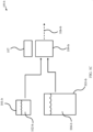
- FIG. 2A shows a system 100-c in accordance with various embodiments where the cooling of a first fluid 104-c may take place before the mixing of the two fluids, including a second fluid 102-c, and formation of a solid.
- System 100-c may be an example of system 100 of FIG. 1A and/or system 100-a of FIG. 1B .
- the process may take place inside a mixing assembly 105.
- the first fluid 104-c may leave a storage container 103-c and may enter a pump 110.
- a pumped first fluid 104-c-1 may then move to a heat exchanger 112 where it may be cooled, producing a chilled first fluid 104-c-2.
- the heat exchanger 112 may be cooled by a refrigerant 113-114.
- the first fluid 104-c-2 may then flow to a mixing nozzle 108 where the second fluid 102-c may be injected into the flow to form a mixed all-liquid flow 106-c.
- the first fluid 104-c-2 and the second fluid 102-c may be immiscible with respect to each other; the second fluid 102-c may be entrained within the first fluid 104-c-2.
- This mixture 106-c then may enter a coil 109-c where it may be hydrodynamically formed into a predictable shape and/or size.
- the cold first fluid 104-c-2 may be warmed by the warmer second fluid 102-c and the heat that may be removed from the second fluid 102-c may cause it to solidify while it may be being hydrodynamically shaped.
- This mixture 106-c-1 may leave the coil 109-c with the second fluid 102-c solidified to the desired degree and may enter the first fluid storage container 103-c where the hydrodynamics change due to changing geometry and the solidified second fluid 106-c-2 may be separated into a packed bed 177. The solid may then be removed 106-c-3 as a mixture of highly concentrated solidified second fluid.
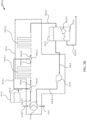
- FIG. 2B shows a system 100-d in accordance with various embodiments.
- System 100-d may be an example of system 100 of FIG. 1A , system 100-a of FIG. 1B , and/or system 100-c of FIG. 2A .
- System 100-d may provide an embodiment in which the cooling of a first fluid 104-d may take place before the mixing of the two fluids, including a second fluid 102-d, and formation of a solid. This process may take place inside a mixing assembly 105-d.
- the first fluid 104-d may leave the storage container 103-d and may enter a pump 110-d.
- the pumped first fluid 104-d-1 may then move to the heat exchanger 112-d where it may be cooled, producing a chilled first fluid 104-d-2.
- the heat exchanger 112-d may be cooled by a refrigerant 113-d/114-d.
- the first fluid 104-d-2 then may flow to a mixing nozzle 108-d-1 where the second fluid 102-d may be injected into the flow to form a mixed all-liquid flow 106-d.
- the first fluid 104-d-2 and the second fluid 102-d may be immiscible with respect to each other; the second fluid 102-d may be entrained within the first fluid 104-d-2.
- This mixture 106-d then may enter a coil 109-d-1 where it may be hydrodynamically formed into a predictable shape and/or size.
- the cold first fluid 104-d-2 may be warmed by the warmer second fluid 102-d and the heat that may be removed from the second fluid 102-d, which may cause it to partially solidify while it may be being hydrodynamically shaped.
- the mixture 106-d-1 may leave the coil 109-d-1 and may enter another injection nozzle 108-d-2 where more second fluid 102-d-1 may be added before the mixture 106-d-2 may enter a second coil 109-d-2.
- the second fluid 102-d may continue to solidify.
- This mixture 106-d-3 may leave the coil 109-d-2 with the second fluid 102-d solidified to the desired degree and may enter the first fluid storage container 103-d where the hydrodynamics change due to changing geometry and the solidified second fluid 106-d-4 may be separated into the packed bed 177-d. The solid may then be removed 106-d-5 as a mixture of highly concentrated solidified second fluid.
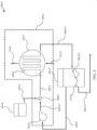
- System 100-e comprises all the features of the independent claim 7.
- System 100-e provides an embodiment in which the cooling of a first fluid 104-e may take place after the mixing of the two fluids, including a second fluid 102-e, and in the process of the formation of the solid. This process may take place inside a mixing assembly 105-e.
- the first fluid 104-e may leave a storage container 103-e and enters a pump 110-e.
- the pumped first fluid 104-e-1then moves to a mixing nozzle 108-e where the second fluid 102-e is injected into the flow to form a mixed all-liquid flow 106-e
- the first fluid 104-e-1 and the second fluid 102-e are immiscible with respect to each other; the second fluid 102-e is entrained within the first fluid 104-e-1.
- This mixture 106-c then enters a coil 109-c where it may be hydrodynamically formed into a predictable shape and/or size.
- the cold first fluid 104-e-1 is warmed by the warmer second fluid 102-c and the heat that is removed from the second fluid 102-c, which causes it to partially solidify while it may be being hydrodynamically shaped.
- This mixture 106-c-1 leaves the coil 109-e with the second fluid 102-e partially solidified and may enter the heat exchanger 112-e where the partially solidified particles may be solidified, completely in some cases, by the cooling effect of the heat exchanger 112-e.
- the heat exchanger 112-e may be cooled by a refrigerant 113-e/114-e.
- the mixture with solidified second fluid 106-e-2 may then enter the first fluid storage container 103-e where the hydrodynamics change due to changing geometry and the solidified second fluid 106-e-3 may be separated into a packed bed 177-e.
- the solid may then be removed 106-e-4 as a mixture of highly concentrated solidified second fluid
- FIG. 4 shows a system 100-f for solid production in accordance with various embodiments.
- System 100-f may be an example of system 100 of FIG. 1A and/or system 100-a of FIG. 1B .
- System 100-f may provide an in which the cooling of a first fluid 104-f takes place simultaneously with the mixing of two fluids, including a second fluid 102-f, and the process of solid formation. This process may take place inside a mixing assembly 105-f.
- the first fluid 104-f may leave a storage container 103-f and may enter a pump 110-f.
- the pumped first fluid 104-f-1 may then move to a mixing nozzle 108-f where the second fluid 102-f may be injected into the flow to form a mixed all-liquid flow 106-f.
- the first fluid 104-f-1 and the second fluid 102-f may be immiscible with respect to each other; the second fluid 102-f may be entrained within the first fluid 100-f-1.
- This mixture 106-f then may enter a coil 109-f where it may be hydrodynamically formed into a predictable shape and/or size.
- the cold first fluid 104-f-1 may be warmed by the warmer second fluid 102-f and the heat that may be removed from the second fluid 102-f, which may cause it to partially solidify while it may be being hydrodynamically shaped.
- the mixture 106-f may be itself cooled by the chilling of the coil's walls via the presence of a refrigerant 113-f/1 14-f on the outside of the coil walls. This cooling may be present because the coil 109-f may be integral to a heat exchanger 112-f.
- the second fluid 102-f While inside the coil 109-f, the second fluid 102-f may be solidified, completely in some cases.
- This mixture 106-f-1 may leave the coil 109-f with the second fluid 102-f solidified, completely in some cases, and may enter the first fluid storage container 103-f where the hydrodynamics change due to changing geometry and the solidified second fluid 106-f-2 may be separated into the packed bed 177-f. The solid may then be removed 106-f-3 as a mixture of highly concentrated solidified second fluid.
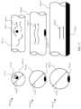
- FIG. 5 cross-sectional and side views of aspects of systems 100-g-1, 100-g-2, and 100-g-3 are provided in accordance with various embodiments. These embodiments may highlight the hydrodynamics of a fully developed flow inside coils 109-g-1, 109-g-2, and 109-g-3, respectively.
- Coils 109-g-1, 109-g-2, and/or 109-g-3 may be examples of surfaces and/or coils 109 of FIG. 1A , FIG. 1B , FIG. 2A , FIG. 2B , FIG. 3 , and/or FIG. 4 . Additionally, the FIG.
- the second fluid may be an example of the second fluid 102 of FIG. 1A or FIG. 1B , for example; the first fluid may be an example of the first fluid 104 of FIG. 1A or FIG. 1B , for example.
- FIG. 5 it may be shown generally how the diameter 116-g of the coil 109-g may produce a different hydrodynamic state, which may determine the solid particle size.
- the coil 109-g-1 with a given diameter 116-g-1 may produce a highly turbulent flow 118-g-1.
- the solid may naturally form a spherical-like particle 115-g-1 from a second fluid that may be born aloft and entrained by the flow of a first fluid.
- the diameter of this particle 117-g-1 may be controllable by not only the coil diameter 116-g-1, but the flow conditions, relative velocities between the fluids, properties of the two fluids, loading ratio of the two fluids, and/or other hydrodynamic forces.
- the diameter 116-g-2 or the flow conditions 118-g-2 within a coil 109-g-2 may be changed such that the flow become less turbulent 118-g-2 and a solid particle shape that may be larger, flatter, and/or more elliptical 115-g-2 may be produced from a second fluid entrained within a first fluid.
- the diameter 116-g-3 and flow conditions 118-g-3 may be changed yet again to produce a fully laminar flow of the first fluid 118-g-3 and a stratified flow of the two fluids 115-g-3, which producing sheets of solidified form of a second fluid.
- FIG. 5 may be exemplary only. It gives an example of how a coil's geometry (i.e., diameter in this case) may be modified to change the shape and/or size of solid produced.
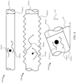
- FIG. 6 provides aspects of systems 100-h-1, 100-h-2, and 100-h-2 that may illustrate the hydrodynamics of the fully developed flow inside coils 109-h-1, 109-h-2, and 109-h-3, respectively.
- Coils 109-h-1, 109-h-2, and/or 109-h-3 may be examples of surfaces and/or coils 109 of FIG. 1A , FIG. 1B , FIG. 2A , FIG. 2B , FIG. 3 , FIG. 4 , and/or FIG. 5 .
- FIG. 6 may illustrate one way that the hydrodynamics can control the formation of predictably shaped and sized solid formed from a second fluid entrained within a first fluid.
- the second fluid may be an example of the second fluid 102 of FIG.
- the first fluid may be an example of the first fluid 104 of FIG. 1A or FIG. 1B , for example.
- FIG. 6 it may be shown how the geometry of the coils 109-h-1, 109-h-2, and/or 109-h-3 can produce a different hydrodynamic state, which may determine the solid particle properties.
- a smooth tube 109-h-1 may be used to produce a spherical ball of solid 115-h-1.
- the diameter 116-h-1 of this tube 109-h-1 may be set such that the flow rate may produce a turbulent flow 118-h-1 capable of carrying the solid 115-h-1 in the flow as in the system 100-g-1 of FIG 5 .
- the surface geometry of the tube 109-h-2 may be modified to increase the turbulence and allow for the hydrodynamic state to be modified.
- the geometry may allow for a change in coil diameter 116-h-2 while maintaining the turbulence 118-h-2 that may be involved to keep the solid 115-h-2 suspended in the flow. This may further allow for the solid 115-h-2 to change in shape and/or size at the same flow rate as a smooth coil.
- the surface geometry may include ribs, riffling, divots, corrugation, and/or any other surface geometry that may affect the turbulence of the second fluid.
- the system 100-h-3 may show a coil 109-h-3 at a non-horizontal angle 119.
- This change may affect the relative gravitational acceleration 120 between the second fluid and the first fluid and again may allow for the shape and size of the first fluid to be modified at a given coil diameter 116-h-3.
- a less turbulent flow 118-h-3 may still produce sufficient lift on the solid particle 115-h-3 to keep it entrained in the fluid and spherical in shape.
- a much larger solid particle 115-h-3 may be achievable at the same tube diameter 116-h-3 and flow rate as either of the other examples.
- FIG. 6 is exemplary only. It gives examples of how the coils geometry (i.e., surface features and tils in this case) may be modified to change the shape and size of solid produced.
- FIG. 7 shows aspects of systems 100-i-1, 100-i-2, 100-i-3, and 100-i-4 in accordance with various embodiments that may show how a coil 109 may not necessarily be a simple homogeneous device. Instead, it may take advantage of multiple geometric aspects to produce various different effects, which may optimally solidify a second fluid entrained within a first fluid.
- the second fluid may be an example of the second fluid 102 of FIG. 1A or FIG. 1B , for example; the first fluid may be an example of the first fluid 104 of FIG. 1A or FIG. 1B , for example.
- Systems 100-i-1, 100-i-2, 100-i-3, and 100-i-4 may be examples of aspects of system 100 of FIG. 1A , system 100-a of FIG.
- system 100-i-1 a simple homogeneous coil 109-i-1 with a constant diameter 116-i-1 may be shown.
- the first fluid 104-i-1 and the second fluid 102-i-1 may be mixed in the mixing nozzle 108-i-1 and then may enter the coil 109-i-1.
- the flow in the coil 109-i-1 may be such that the hydrodynamics automatically create solidifying second fluid 115-i-1 of a certain size and/or shape.
- this mixture 106-i-1 may exit as a combined flow.
- the coil may include two zones 109-i-2-a,109-i-2-b in order to achieve a different solidification outcome.
- the first fluid 104-i-2 and the second fluid 102-i-2 may be mixed in the mixing nozzle 108-i-2 and then may enter the coil.
- the first section of the coil 109-i-2-b may have a specific diameter 116-i-2-b and surface feature that may allow for the solid particle size or shape to be adjusted. For example, it may have a larger diameter at the same flow rate of first fluid. This zone may allow for this larger solid particle to be formed 115-i-2 and partially solidified.
- the solid then may flow into the second zone 109-i-2-a where it may flow through a smooth surface coil and may solidify to the desired outlet condition. In this way, a desired solid particle size may be produced in one section of coil and then may be solidified to a desired amount in a separate section with different flow conditions.
- the mixture 106-i-2 may then exit the coil.
- the coil In system 100-i-3, the coil may be shown with two different diameters.
- the first fluid 104-i-3 and the second fluid 102-i-3 may be mixed in the mixing nozzle 108-i-3 and then may enter the coil.
- the second fluid 115-i-3-a may be formed at one set of flow conditions based on the flow rate and diameter 116-i-3-a.
- the mixed flow then may enter the second section of the coil 109-i-3-b where the diameter 116-i-3-b may be dramatically different, changing the hydrodynamics considerably.
- the second fluid that may be partially solidified in the first section of the coil now may adapt to the new flow conditions.
- This new form 115-i-3-b may include a change in diameter, a change in shape from spherical to elliptical, a change in position/velocity within the coil to manipulate heat transfer, and/or a breakage in the partially solidified particles to re-form into non-geometric highly organic shapes.
- the outlet of this coil may produce a mixed flow 106-i-3 of the two fluids at the desired solidification limit.
- System 100-i-4 may show a coil with two different orientations with respect to gravity and two different diameters. The first fluid 104-i-4 and the second fluid 102-i-4 may be mixed in the mixing nozzle 108-i-4 and then may enter the coil.
- the second fluid 115-i-4-a may be formed at one set of flow conditions based on the flow rate and diameter 116-i-4-a.
- the mixed flow then may enter the second section of the coil, which may also be the storage container 103-i-4 for the first fluid.
- this section of the coil may be considered a container, that may be only because it may have a large overall diameter 116-i-4-b.
- gravitational acceleration may pull the partially solidified second fluid down toward the flow of the mixture from the first section of the coil. This may create a fluidized bed that may continually mix the solidifying second fluid 115-i-4-b with the first fluid coming from the first section of the coil.
- the desirably solidified solid second fluid 106-i-4 may then be taken from the container and the first fluid 104-i-4 may be taken from the container to recirculate through the system.
- FIG. 7 is exemplary in nature.
- the combinations of different sections of the coil may be done in any number of ways and different features may be combined to produce a solid particle or mass of different shape and size. Furthermore, the different sections may be combined in order to produce optimum heat transfer resulting in a desired solid particle size, smaller overall equipment size, and/or more efficient operation.
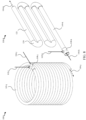
- FIG. 8 provide systems 100-j and 100-k that may show how a coil 109 may be constructed using round cross sections in accordance with various embodiments.
- Systems 100-j and/or 100-k may be examples of aspects of system 100 of FIG. 1A , system 100-a of FIG. 1B , system 100-c of FIG. 2A , system 100-d of FIG. 2B , system 100-e of FIG. 3 , and/or 100-f of FIG. 4 .
- a helical smooth surface coil 109-j may be shown in the first system 100-j.
- a first fluid 104-j may enter the mixing nozzle 108-j where a second fluid 102-j may be injected.
- a mixture 106-j may flow through the coil 109-j until the second fluid 102-j may be solidified to the desired degree.
- a fluid that includes a first fluid 104-k and a second fluid 102-k may flow through a coil 109 -k made of straight sections 121 and curved sections 120.
- the first fluid 104-k may be injected into the mixing nozzle 108-k where it may be mixed with the second fluid 102-k.
- the mixtures may flow through the straight sections 121 and the curved sections 120 until the second fluid 102-k may solidify to a desired level before exiting 106-k.
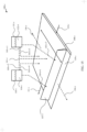
- FIG. 9 provides two views of a system 100-1 that may include a coil 109-l with a rectangular profile in accordance with various embodiments; the views may include an assembled view and an exploded view.
- System 100-l may be an example of aspects of system 100 of FIG. 1A , system 100-a of FIG. 1B , system 100-c of FIG. 2A , system 100-d of FIG. 2B , system 100-e of FIG. 3 , and/or system 100-f of FIG. 4 .
- This example may illustrate that the term coil may not be reserved to circular profiles but may include other profile shapes.
- the coil 109-l may include repeated rectangular plates 123 that may be separated by flow control gaskets 122 that may route the fluid flow, which may include a first fluid 104-l and a second fluid 102-l, from the visual top of the unit to the bottom and then into the next plate 123 where the flow may be opposite and may take the fluid back to the visual top of the coil.
- Addition internal alternating baffles 124 may provide a larger flow length and a desired flow channel dimension.
- the first fluid 104-l and the second fluid 102-l may be injected at the inlet of the coil.
- the mixing nozzle 108-l in this case may be directly integrated into the coil.
- FIG. 9 is exemplary in nature. It may show how the coil described in accordance with various embodiments may not have a circular profile or an overall helical/circular nature.
- FIG. 10 provides a system 100-m in accordance with various embodiments that may highlight another way of controlling the shape and/or size of a solidified second fluid 102-m with respect to a coil 109-m and mixing nozzle 108-m.
- Systems 100-m may be an example of aspects of system 100 of FIG. 1A , system 100-a of FIG. 1B , system 100-c of FIG. 2A , system 100-d of FIG. 2B , system 100-e of FIG. 3 , and/or system 100-f of FIG. 4 .
- a first fluid 104-m may enter the mixing nozzle 108-m through an entrance region 127 and then may enter the mixing nozzle itself 108-m when the fluids carrying the fluids may converge.
- the second fluid 102-m may enter the mixing nozzle 108-m but may not initially mix with the first fluid 104-m; instead, it may run in a tube 141 inside the mixing nozzle 108-m for a length 125 that may allow the flow of the first fluid 104-m to stabilize after the mixing nozzle 108-m.
- This region may exist inside the coil 109-m.
- the diameter of the inner tube 126 may be selected with respect to the diameter 116-m of the coil 109-m such that the shape and/or size of the resulting second fluid 102-m droplets may be well controlled in the outlet mixture 106-m and the final solidified shape of the solidified second fluid 102-m may be controlled.
- the mixing nozzle may also be designed to control the shape and size of the solid. If the diameters of these two tubes 126,116-m may be controlled properly, the relative velocity at the injection point may be controlled. If this relative velocity may be high, a small spherical solid may be created where as if this relative velocity may be low, a larger and elliptical solid may be created. Furthermore, this design may be independent of the flow conditions later downstream in the coil 109-m. As such, it may be possible to use this injection region to establish solid characteristics, such as ice characteristics, before the fully developed coil characteristics take over or to create sections with multiple injection points further downstream with very different properties.
- FIG. 11 provides a system 100-n in accordance with various that may highlight another way of controller the shape and/or size of a solidified second fluid with respect to a coil 109-n and mixing nozzle 108-n in accordance with various embodiments.
- Systems 100-n may be an example of aspects of system 100 of FIG. 1A , system 100-a of FIG. 1B , system 100-c of FIG. 2A , system 100-d of FIG. 2B , system 100-e of FIG. 3 , and/or system 100-f of FIG. 4 .
- a first fluid 104-n may enter the mixing nozzle 108-n through an entrance region 127-n and then may enter the mixing nozzle 108-n itself when the fluids carrying the fluids may converge.
- a second fluid 102-n may enter the mixing nozzle 108-n but may not initially mix with the first fluid 104-n; instead, it may run in a tube 141-n inside the mixing nozzle for a length 125-n that may allow the flow of the first fluid 104-n to stabilize after the mixing nozzle 108-n.
- This region may exist inside the coil 109-n.
- the diameter of the inner tube 126-n and the geometry of the injection nozzle, for example the angle 128, may be selected with respect to the diameter of the coil 116-n such that the shape and/or size of the resulting second fluid droplets may be well controlled in the outlet mixture 106-n and the final solidified shape of the solidified second fluid may be controlled.
- the mixing nozzle 108-n may also be designed to control the shape and/or size of the solid. If the diameters of these two tubes 126-n,116-n may be controlled properly, the relative velocity at the injection point may be controlled. If this relative velocity may be high, a small spherical solid may be created where as if this relative velocity may be low, a larger and elliptical solid may be created. Furthermore, this design may be independent of the flow conditions later downstream in the coil 109-n. As such, it may be possible to use this injection region to establish solid characteristics, such as ice characteristics, before the fully developed coil characteristics may take over or to create sections with multiple injection points further downstream with very different properties.
- some embodiments may utilize a cold surface that may be protected by a first fluid.
- a second fluid may be allowed to come in near contact with the cold surface and solidify.
- the protection from the immiscible fluid may allow for the solid to be removed using a less or minimally complicated and/or low power mechanical device.
- the fluids used in various embodiments are generally immiscible, which may allow for them to physically and/or thermally contact each other throughout the process. Additionally, the first fluid may be chosen based on its affinity for the cold surface. If it has a higher affinity for the surface than the second fluid, surface tension effects may overpower buoyancy or mechanical forces and the cold surface may be protected.
- the first fluid is a non-polar material and the second fluid is a polar material.
- the first fluid may include a hydrocarbon, aromatic, fluorinated, or silicone oil
- an example of the second fluid may include an immiscible polar fluid, such as water, acidic acid, formic acid or other carbocyclic acids, sulfuric acid, ethylene or polyethylene glycol, medium sized alcohols such as tert-butyl, or DMSO.
- the first fluid is a polar material and the second fluid is a non-polar material.
- the first fluid may include water, alcohol, propylene or ethylene glycol, DMSO, ammonia, or nitric acid
- the second fluid may include a fluorinated oil, cresol, a high molecular weight silicon oil, a high molecular weight hydrocarbon oil or paraffin, a thermoset polymer, or a metallic alloy.
- the oil may preferentially cover the surface protecting it even under high hydrostatic or mechanical loading from the water, which may allow for high heat transfer between the water and cold surface but leaving the water poorly adhered to the surface so it may be removed with low power and mechanical complexity.
- FIG. 12 shows a system 100-o for solid production in accordance with various embodiments.
- System 100-o may be an example of system 100 of FIG. 1A and/or system 100-b of FIG. 1C .
- a first fluid 104-o may be released from a storage container 103-o and allowed to flow into a volume 155.
- a second fluid 102-o may be released from a storage container 101-o and allowed to flow into the same volume 155.
- the first fluid 104-o and the second fluid 102-o may be immiscible with respect to each other.
- Inside the volume 155 there may a mechanism such as solid remover 107-o, that may move along a cold surface 109-o that surrounds the volume 155.
- the first fluid 104-o may have an affinity for the surface 109-o such that the second fluid 102-o may approach the cold surface 109-o and may solidify due to its cold temperature, but it cannot adhere well to the surface 109-o.
- the second fluid 102-o may solidify to the desired solid content before leaving the system as a mixture of the first fluid and the second fluid 106-o.
- the cold surface 109-o may be maintained by a second volume 188 that may surround the first volume 155 and may be chilled with a supply of refrigerant 110. Once the refrigerant 110 removes heat from the cold surface 109-o, it may leave the system via as outlet refrigerant 111.
- the first fluid 104-o and the second fluid 102-o may be delivered to the volume 155 and/or cold surfaced 109-o through a variety of conduits 160.
- conduit 160-o-1 may deliver second fluid 102-o to a combiner 161 where it may be combined with the first fluid 104-o delivered through conduit 160-o-2; the combined fluids may then be delivered to the volume 155 and/or cold surface 109-o.
- the first fluid 104-o and the second fluid 102-o may be separately delivered to volume 155 and/or cold surface 109-o.
- conduit 160-o-3 may deliver the second fluid 102-o separately from the first fluid 104-o delivered through conduit 160-o-4.
- the first fluid 104-o may be delivered to the volume 155 and/or cold surface 109-o through conduit 160-o-6that may be coupled with the solid remover 107-o, which may facilitate deliver of the first fluid 104-o to the cold surface 109-o.
- the second fluid 102-o may be delivered to the volume 155 and/or cold surface 109-o through conduit 160-o-5 that may be coupled with the solid remover 107-o, which may facilitate deliver of the second fluid 102-o to the cold surface 109-o.
- the first fluid 104-o may be delivered to the volume 155 and/or cold surface 109-o through conduit 160-o-6 coupled with solid remover 107-o, while the second fluid 102-o may be delivered through conduit 160-o-3.
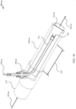
- FIG. 13 shows a system 100-p for solid production in accordance with various embodiments; detail A of system 100-p may be highlighted also.
- System 100-p may be an example of system 100 of FIG. 1A , system 100-b of FIG. 1C , and/or system 100-o of FIG. 12 .
- System 100-p may show an embodiment where a cold surface 109-p is the inside surface of a jacketed tube-in-tube heat exchanger and the solid remover includes an auger 107-p.
- a first fluid 104-p may be supplied to the internal volume 155-p simultaneous to the supply of a second fluid 102-p.
- the first fluid 104-p may have an affinity for the cold surface 109-p.
- the first fluid 104-p and the second fluid 102-p may be immiscible with respect to each other.
- the cold surface 109-p may comprise the entire cylindrical form of the device with the auger 107-p at the center that scrapes the cold surface 109-p.
- the heat may be removed from the cold surface 109-p by a jacketed volume 188-p that may be filled with refrigerant 110-p, and may exit as outlet refrigerant flow 111-p.
- the first fluid 104-p and the second fluid 104-p may leave the volume as a mixture 106-p after the second fluid 102-p has solidified to the desired level.
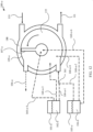
- FIG. 14 shows a system 100-q for solid production in accordance with various embodiments.
- System 100-q may be an example of system 100 of FIG. 1A , system 100-b of FIG. 1C , and/or system 100-o of FIG. 12 .
- a cold surface 109-q may be wrapped around a drum with a rotating tool 107-q inside that may remove the solid.
- a first fluid 104-q may be released from a storage container 103-q while a second fluid 102-q may be released from a second storage container 101-q.
- the first fluid 104-q may have an affinity for the cold surface 109-p.
- the first fluid 104-q and the second fluid 102-q may be immiscible with respect to each other.
- the first fluid 104-q and the second fluid 102-q may flow within a volume 155-q inside the drum that may not occupied by the rotating tool 107-q where the second fluid 102-q solidifies. It then may leave as a mixture of solid and liquid 106-q.
- the drum may be cooled by an external volume that may hold a refrigerant flowing as an inlet flow 110-q to an outlet flow 111-q.
- the first fluid 104-q and the second fluid 102-q may be delivered to the volume 155-q and/or cold surface 109-q through a variety of conduits 160-q.
- conduit 160-q-1 may deliver second fluid 102-q to a combiner 161-q where it may be combined with the first fluid 104-q delivered through conduit 160-q-2; the combined fluids may then be delivered to the volume 155-q and/or cold surface 109-q.
- the first fluid 104-q and the second fluid 102-q may be separately delivered to volume 155-q and/or cold surface 109-q.
- conduit 160-q-3 may deliver the second fluid 102-q separately from the first fluid 104-q delivered through conduit 160-q-4.
- the first fluid 104-q may be delivered to the volume 155-q and/or cold surface 109-q through conduit 160-q-6 that may be coupled with the rotating tool 107-q, which may facilitate deliver of the first fluid 104-q to the cold surface 109-q.
- the second fluid 102-q may be delivered to the volume 155-q and/or cold surface 109-q through conduit 160-q-5 that may be coupled with the rotating tool 107-q, which may facilitate deliver of the second fluid 102-q to the cold surface 109-q.
- the first fluid 104-q may be delivered to the volume 155-q and/or cold surface 109-q through conduit 160-q-6 coupled with rotating tool 107-q, while the second fluid 102-q may be delivered through conduit 160-q-3.
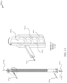
- FIG. 15 shows a system 100-r for solid production in accordance with various embodiments.
- System 100-r may be an example of system 100 of FIG. 1A and/or system 100-b of FIG. 1C .
- a first fluid 104-r may be released from a storage container 103-r, while a second fluid 102-r may be released from a second storage container 101-r.
- the first fluid 104-r and/or the second fluid 102-r may be allowed to flow onto a cold surface 109-r.
- the first fluid 104-r may have an affinity for the cold surface 109-r.
- the first fluid 104-r and the second fluid 102-r may be immiscible with respect to each other.
- the first fluid's affinity for the surface 109-r may mean that the second fluid 102-r may approach the cold surface 109-r and solidify due to its cold temperature, but it cannot adhere well to the surface 109-r. This may allow the mechanism 107-r to remove solid from the surface 107-r at a low speed and torque.
- the second fluid 102-r may solidify to the desired solid content before leaving the surface 109-r as a mixture of the first fluid and the second fluid 106-r.
- the cold surface 109-r may be maintained by a volume 188-r that may boarder one side of the surface 109-r and may be chilled with a supply of refrigerant flow 110-r. Once the refrigerant removes heat from the cold surface 109-r, it may leave the volume 188-r via outlet refrigerant flow 111-r.
- the first fluid 104-r and the second fluid 102-r may be delivered to the cold surface 109-r through a variety of conduits 160-r.
- conduit 160-r-1 may deliver second fluid 102-r to a combiner 161-r where it may be combined with the first fluid 104-r delivered through conduit 160-r-2; the combined fluids may then be delivered to the cold surface 109-r.
- the first fluid 104-r and the second fluid 102-r may be separately delivered to the cold surface 109-r.
- conduit 160-r-3 may deliver the second fluid 102-r separately from the first fluid 104-r delivered through conduit 160-r-4.
- the first fluid 104-r may be delivered to the cold surface 109-r through conduit 160-r-6 that may be coupled with the linear scrapper 107-r, which may facilitate deliver of the first fluid 104-r to the cold surface 109-r.
- the second fluid 102-r may be delivered to the cold surface 109-r through conduit 160-r-5 that may be coupled with the linear scraper 107-r, which may facilitate deliver of the second fluid 102-r to the cold surface 109-r.
- the first fluid 104-r may be delivered to the cold surface 109-r through conduit 160-r-6 coupled with linear scrapper 107-r, while the second fluid 102-r may be delivered through conduit 160-r-3
- FIG. 16 shows a system 100-s for solid production in accordance with various embodiments.
- System 100-s may be an example of system 100 of FIG. 1A , system 100-b of FIG. 1C , and/or system 100-r of FIG. 15 .
- a first fluid 104-s may be released from a storage container 103-s; a second fluid 104-s may be released from a second storage container 101-s.
- the first fluid 104-s and the second fluid 102-s may be immiscible with respect to each other.
- the first fluid 104-s and the second fluid 102-s may be allowed to flow onto a cold surface 109-s.
- the first fluid 104-s may have an affinity for the cold surface 109-s.
- the second fluid 102-s may solidify to the desired solid content before leaving the surface 109-s as a mixture 106-s of the first fluid 104-s and the second fluid 102-s.
- the cold surface 109-s may be maintained at a low temperature by a refrigerant 110-s flowing through a volume directly behind the surface 109-s. Once the refrigerant removes heat from the cold surface 109-s, it may leave the system via an outlet refrigerant flow 111-s.
- the first fluid 104-s and the second fluid 102-s may be delivered to the cold surface 109-s through a variety of conduits 160-s.
- conduit 160-s-1 may deliver second fluid 102-s to a combiner 161-s where it may be combined with the first fluid 104-s delivered through conduit 160-s-2; the combined fluids may then be delivered to the cold surface 109-s.
- the first fluid 104-s and the second fluid 102-s may be separately delivered to the cold surface 109-s.
- conduit 160-s-3 may deliver the second fluid 102-s separately from the first fluid 104-s delivered through conduit 160-s-4.
- the first fluid 104-s may be delivered to the cold surface 109-s through conduit 160-s-6 that may be coupled with the linear scrapper 107-s-1 (and/or linear scrapper 107-s-2), which may facilitate deliver of the first fluid 104-s to the cold surface 109-s.
- the second fluid 102-s may be delivered to the cold surface 109-s through conduit 160-s-5 that may be coupled with the linear scraper 107-s-1 (and/or linear scrapper 107-s-2), which may facilitate deliver of the second fluid 102-s to the cold surface 109-s.
- the first fluid 104-s may be delivered to the cold surface 109-s through conduit 160-s-6 coupled with linear scrapper 107-s-1, while the second fluid 102-s may be delivered through conduit 160-s-3.
- Method 1700 may be implemented by a variety of systems such as those shown in FIG. 1A , FIG. 1B , FIG. 1C , FIG. 2A , FIG. 2B , FIG. 3 , FIG. 4 , FIG. 5 , FIG. 6 , FIG. 7 , FIG. 8 , FIG. 9 , FIG. 10 , FIG. 11 , FIG. 12 , FIG. 13 , FIG. 14 , FIG. 15 , and/or FIG. 16 .
- a first fluid may be contacted with a second fluid to facilitate solidifying the second fluid; the first fluid and the second fluid may be immiscible with respect to each other.
- the second fluid may be solidified.
- the first fluid includes a non-polar material and the second fluid includes a polar material.
- the first fluid includes at least hydrocarbon oil, aromatic oil, fluorinated oil, or silicone oil.
- the second fluid includes at least water, acidic acid, formic acid, carbocyclic acids, sulfuric acid, ethylene glycol, polyethylene glycol, tert-butyl, or DMSO.
- the first fluid includes a polar material and the second fluid includes a non-polar material.
- the first fluid includes at least water, alcohol, propylene glycol, ethylene glycol, DMSO, ammonia, or nitric acid.
- the second fluid includes at least fluorinated oil, cresol, high molecular weight silicon oil, high molecular weight hydrocarbon oil, high molecular weight paraffin, thermoset polymer, or metallic alloy.
- the first fluid includes water and the second fluid includes at least high-molecular weight paraffin or thermoset polymer.
- contacting the first fluid with the second fluid includes entraining the second fluid within the first fluid.
- the first fluid includes aromatic oil and the second fluid includes water.
- Some embodiments further include cooling the first fluid before entraining the second fluid within the first fluid.
- the first fluid and the second fluid are cooled simultaneously.
- entraining the second fluid within the first fluid includes flowing the first fluid and the second fluid through a coil to solidify at least a portion of the second fluid.
- one or more hydrodynamic properties of the first fluid form the second fluid into one or more solidified shapes.
- the one or more solidified shapes may be formed with at least a predictable size or a predictable shape.
- the one or more features of the coil may control the one or more hydrodynamic properties of the first fluid that form the second fluid into the one or more solidified shapes formed with at least the predictable size or the predictable shape.
- the one or more features of the coil may include at least one or more diameters of the coil, one or more geometries of the coil, one or more interior structures of the coil, one or more orientations of the coil, or one or more lengths of the coil.
- the one or more features of the coil may include a change in orientation of the coil.
- the one or more features of the coil may include a change in diameter of the coil.
- entraining the second fluid within the first fluid includes introducing the second fluid as a parallel flow to the first fluid. In some embodiments, entraining the second fluid within the first fluid includes introducing the second fluid as a perpendicular flow to the first fluid.
- contacting the first fluid with the second fluid includes introducing the first fluid and the second fluid with respect to one or more cold surfaces; the first fluid may have an affinity for the one or more cold surfaces. Some embodiments include removing a solidified form of the second fluid from the one or more cold surfaces. The first fluid may coat at least a portion of the one or more cold surfaces and interferes with the second fluid from adhering to the one or more cold surfaces. In some embodiments, the first fluid includes hydrocarbon oil and the second fluid includes water.
- contacting the first fluid with the second fluid includes mixing the second fluid with the first fluid before introducing the first fluid and the second fluid with respect to the one or more cold surfaces. In some embodiments, contacting the first fluid with the second fluid includes separately introducing the first fluid and the second fluid with respect to the one or more cold surfaces.
- the one or more cold surfaces are comprised of a metal. Some embodiments may include other materials such as plastic, ceramic, and/or glass for the one or more cold surfaces.
- removing the solidified form of the second fluid from the one or more cold surfaces includes utilizing an auger to remove the solidified form of the second fluid from a cylindrically-shaped cold surface. In some embodiments, removing the solidified form of the second fluid from the one or more cold surfaces includes utilizing a rotating scrapper to remove the solidified form of the second fluid from a drum-shaped cold surface. In some embodiments, removing the solidified form of the second fluid from the one or more cold surfaces includes utilizing one or more linear scrappers to remove the solidified form of the second fluid from one or more planar cold surfaces.
- FIG. 17B shows a method 1700-a of solid production is provided in accordance with various embodiments.
- Method 1700-a may be implemented by a variety of systems such as those shown in FIG. 1A , FIG. 1B , FIG. 2A , FIG. 2B , FIG. 3 , FIG. 4 , FIG. 5 , FIG. 6 , FIG. 7 , FIG. 8 , FIG. 9 , FIG. 10 , and/or FIG. 11 .
- Method 1700-a may be an example of method 1700 of FIG. 17A .
- a second fluid may be entrained within a first fluid to facilitate solidifying the second fluid; the first fluid and the second fluid may be immiscible with respect to each other.
- the second fluid may be solidified within the first fluid.
- Some embodiments of method 1700-a further include cooling the first fluid before entraining the second fluid within the first fluid. In some embodiments, the first fluid and the second fluid are cooled simultaneously.
- entraining the second fluid within the first fluid includes flowing the first fluid and the second fluid through a coil to solidify at least a portion of the second fluid.
- one or more hydrodynamic properties of the first fluid form the second fluid into one or more solidified shapes.
- the one or more solidified shapes may be formed with at least a predictable size or a predictable shape.
- the one or more features of the coil may control the one or more hydrodynamic properties of the first fluid that form the second fluid into the one or more solidified shapes formed with at least the predictable size or the predictable shape.
- the one or more features of the coil may include at least one or more diameters of the coil, one or more geometries of the coil, one or more interior structures of the coil, one or more orientations of the coil, or one or more lengths of the coil.
- the one or more features of the coil may include a change in orientation of the coil.
- the one or more features of the coil may include a change in diameter of the coil.
- entraining the second fluid within the first fluid includes introducing the second fluid as a parallel flow to the first fluid. In some embodiments, entraining the second fluid within the first fluid includes introducing the second fluid as a perpendicular flow to the first fluid.
- the first fluid includes a non-polar material and the second fluid includes a polar material.
- the first fluid includes at least hydrocarbon oil, aromatic oil, fluorinated oil, or silicone oil.
- the second fluid includes at least water, acidic acid, formic acid, carbocyclic acids, sulfuric acid, ethylene glycol, polyethylene glycol, tert-butyl, or DMSO.
- the first fluid includes aromatic oil and the second fluid includes water.
- the first fluid includes a polar material and the second fluid includes a non-polar material.
- the first fluid includes at least water, alcohol, propylene glycol, ethylene glycol, DMSO, ammonia, or nitric acid.
- the second fluid includes at least fluorinated oil, cresol, high molecular weight silicon oil, high molecular weight hydrocarbon oil, high molecular weight paraffin, thermoset polymer, or metallic alloy.
- the first fluid includes water and the second fluid includes at least high-molecular weight paraffin or thermoset polymer.
- FIG. 17C shows a method 1700-b of solid production is provided in accordance with various embodiments.
- Method 1700-b may be implemented by a variety of systems such as those shown in FIG. 1A , FIG. 1C , FIG. 12 , FIG. 13 , FIG. 14 , FIG. 15 , and/or FIG. 16 .
- Method 1700-b may be an example of method 1700 of FIG. 17A .
- a first fluid and a second fluid may be introduced with respect to one or more cold surfaces.
- the first fluid may have an affinity for the one or more cold surfaces.
- the first fluid and the second fluid may be immiscible with respect to each other.
- the second fluid may be solidified with respect to the one or more cold surfaces.
- a solidified form of the second fluid may be removed from the one or more cold surfaces.
- the first fluid may coat at least a portion of the one or more cold surfaces and interferes with the second fluid from adhering to the one or more cold surfaces.
- the first fluid includes hydrocarbon oil and the second fluid includes water.
- the one or more cold surfaces are comprised of a metal. Some embodiments may include other materials such as plastic, ceramic, and/or glass for the one or more cold surfaces.
- removing the solidified form of the second fluid from the one or more cold surfaces includes utilizing an auger to remove the solidified form of the second fluid from a cylindrically-shaped cold surface. In some embodiments, removing the solidified form of the second fluid from the one or more cold surfaces includes utilizing a rotating scrapper to remove the solidified form of the second fluid from a drum-shaped cold surface. In some embodiments, removing the solidified form of the second fluid from the one or more cold surfaces includes utilizing one or more linear scrappers to remove the solidified form of the second fluid from one or more planar cold surfaces.
- the first fluid includes a non-polar material and the second fluid includes a polar material.
- the first fluid includes at least hydrocarbon oil, aromatic oil, fluorinated oil, or silicone oil.
- the second fluid includes at least water, acidic acid, formic acid, carbocyclic acids, sulfuric acid, ethylene glycol, polyethylene glycol, tert-butyl, or DMSO.
- the first fluid includes hydrocarbon oil and the second fluid includes water.
- the first fluid includes a polar material and the second fluid includes a non-polar material.
- the first fluid includes at least water, alcohol, propylene glycol, ethylene glycol, DMSO, ammonia, or nitric acid.
- the second fluid includes at least fluorinated oil, cresol, high molecular weight silicon oil, high molecular weight hydrocarbon oil, high molecular weight paraffin, thermoset polymer, or metallic alloy.
- the first fluid includes water and the second fluid includes at least high-molecular weight paraffin or thermoset polymer.
- the embodiments may be described as a process which may be depicted as a flow diagram or block diagram or as stages. Although each may describe the operations as a sequential process, many of the operations can be performed in parallel or concurrently. In addition, the order of the operations may be rearranged. A process may have additional stages not included in the figure.
Landscapes
- Engineering & Computer Science (AREA)
- Physics & Mathematics (AREA)
- Mechanical Engineering (AREA)
- Thermal Sciences (AREA)
- General Engineering & Computer Science (AREA)
- Chemical & Material Sciences (AREA)
- Combustion & Propulsion (AREA)
- Heat-Exchange Devices With Radiators And Conduit Assemblies (AREA)
- Physical Or Chemical Processes And Apparatus (AREA)
- Powder Metallurgy (AREA)
Claims (14)
- Verfahren zur Herstellung von Feststoffen, umfassend:Bildung eines ersten Flusses eines ersten Fluids (104) unter Verwendung einer Pumpe (110):Mitführen eines zweiten Fluids (102) innerhalb des ersten Flusses des ersten Fluids, um einen zweiten Fluss zu bilden, der das erste Fluid und das zweite Fluid einschließt, unter Verwendung einer Düse (108), wobei das erste Fluid und das zweite Fluid in Bezug aufeinander nicht mischbar sind:Fließen des zweiten Flusses des zweiten Fluids, das in dem ersten Fluid mitgeführt wird, durch eine Spule (109); undmindestens teilweises Verfestigen des zweiten Fluids, das in dem ersten Fluid mitgeführt wird, innerhalb der Spule aufgrund des Wärmeaustauschs zwischen dem wärmeren zweiten Fluid und dem kalten ersten Fluid.
- Verfahren nach Anspruch 1, wobei das erste Fluid (104) aromatisches Öl einschließt und das zweite Fluid (002) Wasser einschließt.
- Verfahren nach Anspruch 1, ferner umfassend das Kühlen des ersten Fluids (104) vor dem Mitführen des zweiten Fluids (102) in dem ersten Fluid oder wobei das erste Fluid und das zweite Fluid gleichzeitig gekühlt werden.
- Verfahren nach Anspruch 1, wobei:a) eine oder mehrere hydrodynamische Eigenschaften des ersten Fluids (104) das zweite Fluid (102) zu einer oder mehreren verfestigten Formen bilden; und/oderb) die eine oder mehreren verfestigten Formen mindestens mit einer vorhersagbaren Größe oder einer vorhersagbaren Form gebildet werden.
- Verfahren nach Anspruch 4, wobei die eine oder die mehreren verfestigten Formen mit mindestens der vorhersagbaren Größe oder der vorhersagbaren Form gebildet werden, wobei die eine oder die mehreren Merkmale der Spule (109) die eine oder die mehreren hydrodynamischen Eigenschaften des ersten Fluids (104) steuern, die das zweite Fluid (102) zu der einen oder den mehreren verfestigten Formen bilden, die mit mindestens der vorhersagbaren Größe oder der vorhersagbaren Form gebildet werden; optional wobei:a) das eine oder die mehreren Merkmale der Spule mindestens einen oder mehrere Durchmesser der Spule, eine oder mehrere Geometrien der Spule, eine oder mehrere innere Strukturen der Spule, eine oder mehrere Ausrichtungen der Spule oder eine oder mehrere Längen der Spule einschließen;b) das eine oder mehreren Merkmale der Spule eine Änderung der Ausrichtung der Spule einschließen; oderc) wobei das eine oder die mehreren Merkmale der Spule eine Änderung des Durchmessers der Spule einschließen.
- Verfahren nach Anspruch 1, wobei das Mitführen des zweiten Fluids (102) innerhalb des ersten Fluids (104) das Einleiten des zweiten Fluids als einen parallelen Fluss zu dem ersten Fluid einschließt oder wobei das Mitführen des zweiten Fluids innerhalb des ersten Fluids das Einleiten des zweiten Fluids als einen senkrechten Fluss zum ersten Fluid einschließt.
- System (100e) zur Herstellung von Feststoffen nach dem Verfahren von Anspruch 1, umfassend:ein erstes Fluid (104);ein zweites Fluid (102), wobei das erste Fluid und das zweite Fluid in Bezug aufeinander nicht mischbar sind;eine Pumpe (110), die konfiguriert ist, um einen ersten Fluss des ersten Fluids zu bilden;eine Düse (108), die konfiguriert ist, um das zweite Fluid innerhalb des ersten Flusses des ersten Fluids mitzuführen, um einen zweiten Fluss zu bilden, der das erste Fluid und das zweite Fluid einschließt; undeine oder mehrere Spulen (109), die konfiguriert sind, um innerhalb der einen oder mehreren Spulen mindestens einen Abschnitt des zweiten Fluids, das innerhalb des ersten Fluids mitgeführt wird, aufgrund des Wärmeaustauschs zwischen dem wärmeren zweiten Fluid und dem kalten ersten Fluid mindestens teilweise zu verfestigen.
- System nach Anspruch 7, wobei das erste Fluid (104) ein unpolares Material einschließt und das zweite Fluid (102) ein polares Material einschließt, und optional wobei;a) das erste Fluid mindestens Kohlenwasserstofföl, aromatisches Öl, fluoriertes Öl oder Silikonöl einschließt; und/oderb) das zweite Fluid mindestens Wasser, saure Säure, Ameisensäure, carbocyclische Säuren, Schwefelsäure, Ethylenglykol, Polyethylenglykol, tert.-Butyl oder DMSO einschließt.
- System nach Anspruch 7, wobei das erste Fluid (104) ein polares Material einschließt und das zweite Fluid (102) ein unpolares Material einschließt, und optional wobeia) das erste Fluid mindestens Wasser, Alkohol, Propylenglykol, Ethylenglykol, DMSO, Ammoniak oder Salpetersäure einschließt;b) das zweite Fluid mindestens fluoriertes Öl, Kresol, hochmolekulares Silikonöl, hochmolekulares Kohlenwasserstofföl, hochmolekulares Paraffin, duroplastisches Polymer oder eine Metalllegierung einschließt; und/oderc) das erste Fluid Wasser einschließt und das zweite Fluid mindestens hochmolekulares Paraffin oder duroplastisches Polymer einschließt.
- System nach Anspruch 7, wobei das erste Fluid (104) aromatisches Öl einschließt und das zweite Fluid (102) Wasser einschließt.
- System gemäß Anspruch 7, wobei:a) das System ferner einen Wärmetauscher (112) umfasst, der so positioniert ist, dass er das erste Fluid kühlt, bevor das zweite Fluid in das erste Fluid mitgeführt wird; oderb) das erste Fluid und das zweite Fluid gleichzeitig in der einen oder den mehreren Spulen (109) gekühlt werden.
- System nach Anspruch 7, wobei eine oder mehrere hydrodynamische Eigenschaften des ersten Fluids (104) innerhalb der einen oder mehreren Spulen (109) das zweite Fluid (102) zu einer oder mehreren verfestigten Formen bilden, wobei optional die eine oder mehreren verfestigten Formen mit mindestens einer vorhersagbaren Größe oder einer vorhersagbaren Form gebildet werden.
- System nach Anspruch 12, wobei, wenn die eine oder die mehreren verfestigten Formen mit mindestens einer vorhersagbaren Größe oder einer vorhersagbaren Form gebildet werden, ein oder mehrere Merkmale der Spule (109) die eine oder die mehreren hydrodynamischen Eigenschaften des ersten Fluids (104) steuern, die das zweite Fluid (102) zu der einen oder den mehreren verfestigten Formen bilden, die mit mindestens der vorhersagbaren Größe oder der vorhersagbaren Form gebildet werden, und optional wobei:a) das eine oder die mehreren Merkmale der Spule mindestens einen oder mehrere Durchmesser der Spule, eine oder mehrere Geometrien der Spule, eine oder mehrere innere Strukturen der Spule, eine oder mehrere Ausrichtungen der Spule oder eine oder mehrere Längen der Spule einschließen;b) das eine oder mehreren Merkmale der Spule eine Änderung der Ausrichtung der Spule einschließen; und/oderc) das eine oder die mehreren Merkmale der Spule eine Änderung des Durchmessers der Spule einschließen.
- System nach Anspruch 7, ferner umfassenda) ein Rohr (141), das innerhalb der Düse (108) so positioniert ist, dass das zweite Fluid (102) als ein paralleler Fluss zu dem ersten Fluid (104) eingeleitet wird; oderb) ein Rohr (141), das innerhalb der Düse (108) so positioniert ist, dass das zweite Fluid (102) als ein senkrechter Fluss zu dem ersten Fluid (104) eingeleitet wird.
Applications Claiming Priority (3)
| Application Number | Priority Date | Filing Date | Title |
|---|---|---|---|
| US201762553738P | 2017-09-01 | 2017-09-01 | |
| US16/119,661 US10544974B2 (en) | 2017-09-01 | 2018-08-31 | Solid production methods, systems, and devices |
| PCT/US2018/049288 WO2019046836A1 (en) | 2017-09-01 | 2018-09-01 | METHODS, SYSTEMS AND DEVICES FOR PRODUCING SOLID |
Publications (4)
| Publication Number | Publication Date |
|---|---|
| EP3676546A1 EP3676546A1 (de) | 2020-07-08 |
| EP3676546A4 EP3676546A4 (de) | 2021-06-02 |
| EP3676546C0 EP3676546C0 (de) | 2025-04-30 |
| EP3676546B1 true EP3676546B1 (de) | 2025-04-30 |
Family
ID=65526089
Family Applications (1)
| Application Number | Title | Priority Date | Filing Date |
|---|---|---|---|
| EP18851112.5A Active EP3676546B1 (de) | 2017-09-01 | 2018-09-01 | Verfahren und system zur herstellung von feststoffen |
Country Status (7)
| Country | Link |
|---|---|
| US (2) | US10544974B2 (de) |
| EP (1) | EP3676546B1 (de) |
| JP (2) | JP7171706B2 (de) |
| CN (1) | CN111065870B (de) |
| CA (1) | CA3074509A1 (de) |
| ES (1) | ES3034061T3 (de) |
| WO (1) | WO2019046836A1 (de) |
Families Citing this family (9)
| Publication number | Priority date | Publication date | Assignee | Title |
|---|---|---|---|---|
| US10544974B2 (en) | 2017-09-01 | 2020-01-28 | Rebound Technologies, Inc. | Solid production methods, systems, and devices |
| KR102468817B1 (ko) * | 2018-02-26 | 2022-11-21 | 삼성전자 주식회사 | 제빙장치 |
| CN112236639A (zh) | 2018-04-04 | 2021-01-15 | 活化能量系统公司 | 用于冻结相变材料的换热系统及其方法 |
| US11441830B2 (en) | 2018-12-26 | 2022-09-13 | Rebound Technologies, Inc. | Solid production systems, devices, and methods utilizing oleophilic surfaces |
| EP4055331B1 (de) | 2019-11-06 | 2025-07-30 | Abstract Ice, Inc. | Verfahren zur herstellung von klareis |
| EP4130595A4 (de) | 2020-03-25 | 2024-04-03 | Daikin Industries, Ltd. | Klimaanlagensteuerungssystem |
| EP4248152A4 (de) | 2020-11-20 | 2024-12-11 | Abstract Ice, Inc. | Vorrichtungen zur herstellung von klareisprodukten und zugehörige verfahren |
| JP2023010634A (ja) | 2021-07-07 | 2023-01-20 | ニコ コーポレイション | 可撓性器具送達デバイス |
| WO2024163881A1 (en) | 2023-02-02 | 2024-08-08 | Abstract Ice, Inc. | Devices for shaping clear ice products and related methods |
Citations (1)
| Publication number | Priority date | Publication date | Assignee | Title |
|---|---|---|---|---|
| US20170167770A1 (en) * | 2014-08-28 | 2017-06-15 | Abb Schweiz Ag | Method and apparatus for solidifying a polar substance |
Family Cites Families (26)
| Publication number | Priority date | Publication date | Assignee | Title |
|---|---|---|---|---|
| US3650121A (en) * | 1969-12-22 | 1972-03-21 | Borg Warner | Icemaker protection system |
| US3906742A (en) * | 1972-12-04 | 1975-09-23 | Borg Warner | Air conditioning system utilizing ice slurries |
| US3869870A (en) | 1973-07-02 | 1975-03-11 | Borg Warner | Refrigeration system utilizing ice slurries |
| DE3264450D1 (en) | 1981-12-11 | 1985-08-01 | Wyeth John & Brother Ltd | Process and apparatus for freezing a liquid medium |
| SE446356B (sv) * | 1985-01-17 | 1986-09-01 | Atlas Copco Ab | Forfarande och anordning vid en vermepumps forangarsida der koldmedium i vetskeform och en vetska blandas vid hogre tryck en forangningstrycket |
| WO1987007250A1 (en) * | 1986-05-23 | 1987-12-03 | Robert Blackmore Collins | Freezing process |
| JPS6410076A (en) * | 1987-07-01 | 1989-01-13 | Hitachi Zosen Tank Syst Kk | Liquid ice production unit |
| US4907415A (en) | 1988-11-23 | 1990-03-13 | The Curator Of The University Of Missouri | Slush ice making system and methods |
| US4953360A (en) | 1989-09-27 | 1990-09-04 | Slick Ice Limited | Additive for treating water used to form ice |
| JPH07104083B2 (ja) * | 1990-12-28 | 1995-11-13 | 鹿島建設株式会社 | 冷媒噴出式氷利用蓄熱方法及び装置 |
| JP3344813B2 (ja) * | 1994-03-15 | 2002-11-18 | 東芝キヤリア株式会社 | ダイナミック型氷蓄熱装置 |
| US5858957A (en) | 1995-01-26 | 1999-01-12 | The Procter & Gamble Company | Process for the manufacture of granular detergent compositions comprising nonionic surfactant |
| JPH10185379A (ja) * | 1996-10-31 | 1998-07-14 | Tetsuo Kawagoe | 製氷システム又は氷蓄熱システム |
| US6119467A (en) | 1997-11-20 | 2000-09-19 | Brontec U.S.A., Inc. | Method and installation for continuous production of whipped ice |
| JPH11281214A (ja) * | 1998-03-26 | 1999-10-15 | Kandenko Co Ltd | 直接接触式製氷方法およびその装置 |
| FR2795810B1 (fr) * | 1999-06-30 | 2001-08-31 | Mc Internat | Procede d'echange thermique par un fluide frigoporteur diphasique liquide solide |
| DK1392789T3 (da) | 2001-05-08 | 2010-07-19 | Danish Technological Inst Ener | Isafvisende belægninger på afkølede overflader til isdannelse |
| US20040167231A1 (en) * | 2003-02-20 | 2004-08-26 | Tetsuo Kawagoe | Method for producing W/O-type suspension |
| CN1243942C (zh) * | 2003-11-07 | 2006-03-01 | 东南大学 | 制作流体冰的方法及装置 |
| JP2007535652A (ja) | 2004-05-01 | 2007-12-06 | アグリサーチ リミティド | 乾燥工程及び装置 |
| CN100485293C (zh) * | 2006-01-12 | 2009-05-06 | 哈尔滨工业大学 | 基于壁面弹性变形剥冰提取凝固潜热制取流体冰的方法 |
| CN201787782U (zh) * | 2010-08-13 | 2011-04-06 | 黎加雄 | 一种改进的制冰筒 |
| US9310140B2 (en) | 2012-02-07 | 2016-04-12 | Rebound Technologies, Inc. | Methods, systems, and devices for thermal enhancement |
| US20150210951A1 (en) * | 2012-07-13 | 2015-07-30 | President And Fellows Of Harvard College | Multifunctional repellent materials |
| US10544974B2 (en) | 2017-09-01 | 2020-01-28 | Rebound Technologies, Inc. | Solid production methods, systems, and devices |
| US11441830B2 (en) | 2018-12-26 | 2022-09-13 | Rebound Technologies, Inc. | Solid production systems, devices, and methods utilizing oleophilic surfaces |
-
2018
- 2018-08-31 US US16/119,661 patent/US10544974B2/en active Active
- 2018-09-01 CA CA3074509A patent/CA3074509A1/en active Pending
- 2018-09-01 WO PCT/US2018/049288 patent/WO2019046836A1/en not_active Ceased
- 2018-09-01 EP EP18851112.5A patent/EP3676546B1/de active Active
- 2018-09-01 ES ES18851112T patent/ES3034061T3/es active Active
- 2018-09-01 JP JP2020512576A patent/JP7171706B2/ja active Active
- 2018-09-01 CN CN201880056526.8A patent/CN111065870B/zh active Active
-
2020
- 2020-01-23 US US16/750,170 patent/US11236935B2/en active Active
-
2022
- 2022-11-02 JP JP2022176027A patent/JP7256921B2/ja active Active
Patent Citations (1)
| Publication number | Priority date | Publication date | Assignee | Title |
|---|---|---|---|---|
| US20170167770A1 (en) * | 2014-08-28 | 2017-06-15 | Abb Schweiz Ag | Method and apparatus for solidifying a polar substance |
Also Published As
| Publication number | Publication date |
|---|---|
| US11236935B2 (en) | 2022-02-01 |
| EP3676546C0 (de) | 2025-04-30 |
| CA3074509A1 (en) | 2019-03-07 |
| EP3676546A4 (de) | 2021-06-02 |
| WO2019046836A1 (en) | 2019-03-07 |
| JP2023002821A (ja) | 2023-01-10 |
| US20200263913A1 (en) | 2020-08-20 |
| JP7256921B2 (ja) | 2023-04-12 |
| US10544974B2 (en) | 2020-01-28 |
| JP7171706B2 (ja) | 2022-11-15 |
| ES3034061T3 (en) | 2025-08-12 |
| JP2020532704A (ja) | 2020-11-12 |
| EP3676546A1 (de) | 2020-07-08 |
| CN111065870B (zh) | 2022-06-03 |
| CN111065870A (zh) | 2020-04-24 |
| US20190101315A1 (en) | 2019-04-04 |
Similar Documents
| Publication | Publication Date | Title |
|---|---|---|
| EP3676546B1 (de) | Verfahren und system zur herstellung von feststoffen | |
| US7968020B2 (en) | Hot asphalt cooling and pelletization process | |
| US10305153B2 (en) | Micro heat exchangers and methods for use in thermal management of transportation vehicle batteries | |
| WO2015134940A1 (en) | High-performance tool cooling system | |
| EP3123083B1 (de) | Kühlsystem mit speicherstoffwärmetauscher | |
| JP2020532704A5 (de) | ||
| Mirabedin et al. | Numerical investigation of solidification of single droplets with and without evaporation mechanism | |
| JP2021520478A (ja) | 相変化材料を凍結するための熱交換システム及び相変化材料を凍結する方法 | |
| SE408955B (sv) | Forfarande och anordning for att lagra vermeenergi | |
| CN106347702B (zh) | 一种喷气导流板 | |
| US20070245766A1 (en) | In-line beverage chilling apparatus | |
| US20160146542A1 (en) | Shell and tube heat exchanger | |
| Guo et al. | Singular ratchet-valley structure inducing droplet directional transport crossing all boiling states | |
| US7062924B2 (en) | Method and apparatus for the manipulation and management of a cryogen for production of frozen small volumes of a substance | |
| HK40029088A (en) | Solid production methods, systems, and devices | |
| HK40029088B (en) | Solid production methods, systems, and devices | |
| KR20230045017A (ko) | 상변화물질의 동결, 전달, 보관 및 활용을 위한 열교환 시스템 및 해당 시스템의 열 에너지 저장 시스템에의 적용 | |
| JP2006183970A (ja) | 蓄熱装置 | |
| Tanner | Droplet freezing and solidification | |
| Chang et al. | An advanced thermal control technique for aircraft anti-icing/de-icing based on loop heat pipes | |
| CN108351145A (zh) | 用于冷却液体的设备和方法以及设备作为用于存储装置的部件的用途 | |
| Zhang et al. | Experimental investigation of dual-feed recirculation in cryogenic propellant transfer system | |
| WO2004065877A1 (en) | Thermal storage apparatus | |
| JPH03244985A (ja) | 製氷装置 | |
| TW201226075A (en) | Device for maintaining wax at constant temperature rapidly |
Legal Events
| Date | Code | Title | Description |
|---|---|---|---|
| STAA | Information on the status of an ep patent application or granted ep patent |
Free format text: STATUS: THE INTERNATIONAL PUBLICATION HAS BEEN MADE |
|
| PUAI | Public reference made under article 153(3) epc to a published international application that has entered the european phase |
Free format text: ORIGINAL CODE: 0009012 |
|
| STAA | Information on the status of an ep patent application or granted ep patent |
Free format text: STATUS: REQUEST FOR EXAMINATION WAS MADE |
|
| 17P | Request for examination filed |
Effective date: 20200326 |
|
| AK | Designated contracting states |
Kind code of ref document: A1 Designated state(s): AL AT BE BG CH CY CZ DE DK EE ES FI FR GB GR HR HU IE IS IT LI LT LU LV MC MK MT NL NO PL PT RO RS SE SI SK SM TR |
|
| AX | Request for extension of the european patent |
Extension state: BA ME |
|
| DAV | Request for validation of the european patent (deleted) | ||
| DAX | Request for extension of the european patent (deleted) | ||
| REG | Reference to a national code |
Ref country code: DE Ipc: F25C0001000000 Ref country code: DE Ref legal event code: R079 Ref document number: 602018081594 Country of ref document: DE Free format text: PREVIOUS MAIN CLASS: F25C0001120000 Ipc: F25C0001000000 |
|
| A4 | Supplementary search report drawn up and despatched |
Effective date: 20210504 |
|
| RIC1 | Information provided on ipc code assigned before grant |
Ipc: F25C 1/00 20060101AFI20210428BHEP Ipc: F25C 1/12 20060101ALI20210428BHEP |
|
| STAA | Information on the status of an ep patent application or granted ep patent |
Free format text: STATUS: EXAMINATION IS IN PROGRESS |
|
| 17Q | First examination report despatched |
Effective date: 20221205 |
|
| P01 | Opt-out of the competence of the unified patent court (upc) registered |
Effective date: 20230514 |
|
| GRAP | Despatch of communication of intention to grant a patent |
Free format text: ORIGINAL CODE: EPIDOSNIGR1 |
|
| STAA | Information on the status of an ep patent application or granted ep patent |
Free format text: STATUS: GRANT OF PATENT IS INTENDED |
|
| RIC1 | Information provided on ipc code assigned before grant |
Ipc: F25C 1/14 20180101ALI20240506BHEP Ipc: F25C 1/12 20060101ALI20240506BHEP Ipc: F25C 1/00 20060101AFI20240506BHEP |
|
| INTG | Intention to grant announced |
Effective date: 20240605 |
|
| GRAJ | Information related to disapproval of communication of intention to grant by the applicant or resumption of examination proceedings by the epo deleted |
Free format text: ORIGINAL CODE: EPIDOSDIGR1 |
|
| STAA | Information on the status of an ep patent application or granted ep patent |
Free format text: STATUS: EXAMINATION IS IN PROGRESS |
|
| GRAP | Despatch of communication of intention to grant a patent |
Free format text: ORIGINAL CODE: EPIDOSNIGR1 |
|
| STAA | Information on the status of an ep patent application or granted ep patent |
Free format text: STATUS: GRANT OF PATENT IS INTENDED |
|
| INTC | Intention to grant announced (deleted) | ||
| INTG | Intention to grant announced |
Effective date: 20241016 |
|
| GRAS | Grant fee paid |
Free format text: ORIGINAL CODE: EPIDOSNIGR3 |
|
| GRAA | (expected) grant |
Free format text: ORIGINAL CODE: 0009210 |
|
| STAA | Information on the status of an ep patent application or granted ep patent |
Free format text: STATUS: THE PATENT HAS BEEN GRANTED |
|
| AK | Designated contracting states |
Kind code of ref document: B1 Designated state(s): AL AT BE BG CH CY CZ DE DK EE ES FI FR GB GR HR HU IE IS IT LI LT LU LV MC MK MT NL NO PL PT RO RS SE SI SK SM TR |
|
| REG | Reference to a national code |
Ref country code: CH Ref legal event code: EP Ref country code: GB Ref legal event code: FG4D |
|
| REG | Reference to a national code |
Ref country code: IE Ref legal event code: FG4D |
|
| REG | Reference to a national code |
Ref country code: DE Ref legal event code: R096 Ref document number: 602018081594 Country of ref document: DE |
|
| U01 | Request for unitary effect filed |
Effective date: 20250528 |
|
| P04 | Withdrawal of opt-out of the competence of the unified patent court (upc) registered |
Free format text: CASE NUMBER: APP_26165/2025 Effective date: 20250602 |
|
| U07 | Unitary effect registered |
Designated state(s): AT BE BG DE DK EE FI FR IT LT LU LV MT NL PT RO SE SI Effective date: 20250605 |
|
| REG | Reference to a national code |
Ref country code: ES Ref legal event code: FG2A Ref document number: 3034061 Country of ref document: ES Kind code of ref document: T3 Effective date: 20250812 |
|
| PG25 | Lapsed in a contracting state [announced via postgrant information from national office to epo] |
Ref country code: NO Free format text: LAPSE BECAUSE OF FAILURE TO SUBMIT A TRANSLATION OF THE DESCRIPTION OR TO PAY THE FEE WITHIN THE PRESCRIBED TIME-LIMIT Effective date: 20250730 Ref country code: GR Free format text: LAPSE BECAUSE OF FAILURE TO SUBMIT A TRANSLATION OF THE DESCRIPTION OR TO PAY THE FEE WITHIN THE PRESCRIBED TIME-LIMIT Effective date: 20250731 |
|
| PG25 | Lapsed in a contracting state [announced via postgrant information from national office to epo] |
Ref country code: PL Free format text: LAPSE BECAUSE OF FAILURE TO SUBMIT A TRANSLATION OF THE DESCRIPTION OR TO PAY THE FEE WITHIN THE PRESCRIBED TIME-LIMIT Effective date: 20250430 |
|
| PG25 | Lapsed in a contracting state [announced via postgrant information from national office to epo] |
Ref country code: HR Free format text: LAPSE BECAUSE OF FAILURE TO SUBMIT A TRANSLATION OF THE DESCRIPTION OR TO PAY THE FEE WITHIN THE PRESCRIBED TIME-LIMIT Effective date: 20250430 |
|
| PG25 | Lapsed in a contracting state [announced via postgrant information from national office to epo] |
Ref country code: RS Free format text: LAPSE BECAUSE OF FAILURE TO SUBMIT A TRANSLATION OF THE DESCRIPTION OR TO PAY THE FEE WITHIN THE PRESCRIBED TIME-LIMIT Effective date: 20250731 |
|
| PG25 | Lapsed in a contracting state [announced via postgrant information from national office to epo] |
Ref country code: IS Free format text: LAPSE BECAUSE OF FAILURE TO SUBMIT A TRANSLATION OF THE DESCRIPTION OR TO PAY THE FEE WITHIN THE PRESCRIBED TIME-LIMIT Effective date: 20250830 |