EP3676150B1 - Sitzeinheit und mobile einheit - Google Patents
Sitzeinheit und mobile einheit Download PDFInfo
- Publication number
- EP3676150B1 EP3676150B1 EP18793573.9A EP18793573A EP3676150B1 EP 3676150 B1 EP3676150 B1 EP 3676150B1 EP 18793573 A EP18793573 A EP 18793573A EP 3676150 B1 EP3676150 B1 EP 3676150B1
- Authority
- EP
- European Patent Office
- Prior art keywords
- seat
- elements
- supporting
- unit
- support arm
- Prior art date
- Legal status (The legal status is an assumption and is not a legal conclusion. Google has not performed a legal analysis and makes no representation as to the accuracy of the status listed.)
- Active
Links
Images


Classifications
-
- B—PERFORMING OPERATIONS; TRANSPORTING
- B61—RAILWAYS
- B61D—BODY DETAILS OR KINDS OF RAILWAY VEHICLES
- B61D33/00—Seats
- B61D33/0057—Seats characterised by their mounting in vehicles
- B61D33/0064—Seats characterised by their mounting in vehicles not adjustably mounted; supports therefor
-
- B—PERFORMING OPERATIONS; TRANSPORTING
- B60—VEHICLES IN GENERAL
- B60N—SEATS SPECIALLY ADAPTED FOR VEHICLES; VEHICLE PASSENGER ACCOMMODATION NOT OTHERWISE PROVIDED FOR
- B60N2/00—Seats specially adapted for vehicles; Arrangement or mounting of seats in vehicles
-
- B—PERFORMING OPERATIONS; TRANSPORTING
- B60—VEHICLES IN GENERAL
- B60N—SEATS SPECIALLY ADAPTED FOR VEHICLES; VEHICLE PASSENGER ACCOMMODATION NOT OTHERWISE PROVIDED FOR
- B60N2/00—Seats specially adapted for vehicles; Arrangement or mounting of seats in vehicles
- B60N2/005—Arrangement or mounting of seats in vehicles, e.g. dismountable auxiliary seats
- B60N2/015—Attaching seats directly to vehicle chassis
-
- B—PERFORMING OPERATIONS; TRANSPORTING
- B60—VEHICLES IN GENERAL
- B60N—SEATS SPECIALLY ADAPTED FOR VEHICLES; VEHICLE PASSENGER ACCOMMODATION NOT OTHERWISE PROVIDED FOR
- B60N2/00—Seats specially adapted for vehicles; Arrangement or mounting of seats in vehicles
- B60N2/24—Seats specially adapted for vehicles; Arrangement or mounting of seats in vehicles for particular purposes or particular vehicles
- B60N2/242—Bus seats
-
- B—PERFORMING OPERATIONS; TRANSPORTING
- B61—RAILWAYS
- B61D—BODY DETAILS OR KINDS OF RAILWAY VEHICLES
- B61D33/00—Seats
- B61D33/0057—Seats characterised by their mounting in vehicles
Definitions
- the invention relates to a seat unit with at least one support arm, the seat being attached to the support arm using support elements, each of the support elements comprising at least one seat attachment element, by means of which the respective support element is firmly connected to the seat, and wherein the Supporting elements are arranged such that the seat fasteners are arranged outside of the support arm.
- the invention relates to a mobile unit with such a seat unit.
- a seat unit of the above type is, for example, from DE 20 2014 103167 U1 known.
- the support elements used there have a general triangular shape and encompass a provided support arm.
- a support arm adapted to the seat type is developed for each seat type.
- the support arm includes threaded holes for attaching the seat.
- the threaded holes must be made in different positions in the support arm.
- WO 2013/164151 A1 a support arm is provided, with seat fasteners having threaded holes being positioned within the support arm. However, no seats can be attached to this seat carrier whose attachment points are too far apart.
- An object of the invention is to provide a seat unit that is simple in structure, wherein the seat can be flexibly selected and flexibly arranged.
- the seat is preferably firmly connected to the support elements, in particular via the seat fastening elements.
- the support elements are expediently firmly connected to the support arm.
- At least one of the connections can be a detachable connection.
- at least one of the connections can be a non-detachable connection.
- the support elements are preferably fastened to the seat, in particular via the seat fastening elements. Furthermore, the support elements are preferably attached to the support arm.
- the seat unit expediently includes the support elements.
- the position of the supporting elements can be chosen freely, in particular depending on the seat chosen. This means that the support elements can preferably be freely positioned. In particular, the seat attachment elements can be positioned freely. Due to the use of the support elements, the seat can be freely positioned relative to the support arm in all three spatial directions. In this way, the position of the seat is preferably not defined and/or limited by a dimension of the support arm.
- the seat can be selected flexibly in this way.
- the seat can also be arranged flexibly in this way.
- a single type of support arm can be used for a wide variety of seat types. In this way, costs such as development costs, storage costs, etc. can be reduced.
- the seat unit according to the invention can have further advantages: the seat unit is expediently of simple construction. Preferably, the seat unit is also easy to assemble. It is also advantageous if the seat unit requires little maintenance. In addition, the seat unit can have a particularly low weight. Furthermore, the seat unit can be inexpensive. For example, manufacturing costs, maintenance costs, and/or transportation costs can be low.
- the seat unit can be a seat unit for a stationary unit, for example for a building.
- the seat unit is a seat unit for a mobile unit, in particular for a vehicle.
- the seat can be a passenger seat for a vehicle, for example for a bus, for a mobile home, for a rail vehicle, for an airplane, for a ship or the like.
- the seat unit can be a seat unit for part of a vehicle, for example for a carriage of a rail vehicle.
- the seat can, for example, be designed as a single seat for a single person.
- the seat z. B. be designed as a bench for several people.
- the seat expediently comprises at least one seat surface element. Furthermore, the seat can have a backrest and/or at least one armrest.
- the support arm is elongate.
- the seat is expediently fastened to the support arm using the support elements.
- the seat is immovable relative to the support arm using the support elements. That is, the seat cannot be moved relative to the support arm using the support members.
- the support members do not allow movement of the seat relative to the support arm.
- each of the seat fasteners is fixedly connected to the seat. It is advantageous if each of the seat attachment elements is detachably connected to the seat. For example, each of the seat attachment elements can be connected to the seat using a clamp connection.
- each of the seat fastening elements is connected to the seat using a screw connection.
- each of the seat fasteners may each include a threaded bore.
- Each of the support elements is preferably firmly connected to the support arm.
- Each of the support elements can be detachably connected to the support arm. It is advantageous if each of the support elements is non-detachably connected to the support arm.
- each of the support elements is advantageously connected to the support arm using a welded connection.
- the support arm has a plurality of recesses.
- Each of the support elements is partially inserted in at least one of the recesses.
- the support elements are expediently inserted in such a way that the seat fastening elements are arranged outside of the support arm. That is, it is preferred if the seat fasteners are not inserted into the recesses.
- the recesses can have been made in the support arm using laser cutting, for example.
- the shape of the respective recess is expediently adapted to the shape of the respective support element. Furthermore, the shape of the respective support element can be adapted to the shape of the respective recess.
- the recesses are each formed in the shape of a slot.
- each of the support elements has an insertable rib.
- the respective insertable rib is expediently at least partially inserted into the support arm.
- the respective insertable rib is at least partially inserted and/or inserted into a respective recess of the support arm.
- the rib is preferably at least essentially plate-shaped.
- One of the ribs is expediently connected firmly to at least one of the seat fastening elements.
- one of the ribs can be non-detachably connected to at least one of the seat attachment elements, e.g. B. each using a welded joint.
- the support element can be made in one piece.
- each of the support members has two opposite ends in its longitudinal direction.
- each of the support elements comprises two seat fastening elements.
- the respective two seat fastening elements are expediently arranged at the opposite ends of the respective support element.
- the longitudinal direction of the respective support element can in each case run essentially parallel to a transverse direction of the support arm.
- the longitudinal direction of the respective support element preferably runs at least essentially horizontally. That direction of the support arm which runs perpendicularly to a longitudinal direction of the support arm can be understood as the transverse direction of the Tararms. This means that the longitudinal direction of the respective support element can in each case run essentially perpendicularly to the longitudinal direction of the support arm.
- the direction of the longest extent of this element can be understood as the longitudinal direction of an element.
- the transverse direction of an element runs perpendicular to the longitudinal direction of this element. It is also advantageous if the transverse direction runs at least essentially horizontally.
- each of the support elements comprises the aforementioned rib
- a flat side of the rib can be at least substantially perpendicular to the longitudinal direction of the support arm.
- each of the support elements can each have a connecting surface.
- the respective shape of the respective connection surface is preferably adapted to the shape of a surface of the support arm.
- Each of the connecting surfaces can be firmly connected to the surface of the support arm.
- the seat may be spaced from the support arm using the support members.
- the seat may partially touch a surface of the support arm.
- the support arm is preferably an endless profile that has been brought to a predetermined length.
- the support arm can be a roll-formed endless profile brought to a predetermined length.
- the support arm can be an extruded profile cut to a predetermined length.
- the support arm can be in several parts.
- the support arm is preferably in two parts at most.
- the support arm can be in one piece.
- the seat unit can have further elements.
- the seat unit can have means for attaching the support arm.
- the support arm can be attached to a floor and/or to a side wall of a mobile or a stationary unit using the means for attaching the support arm.
- the mobile or stationary unit can be the aforementioned mobile or stationary unit.
- the support arm can be designed, for example, as a cantilever support arm for exclusive attachment to a side wall of a mobile unit.
- the means for attaching the support arm can be a means for only attaching the support arm to the side wall of the mobile unit.
- the mobile unit can be the aforementioned mobile unit.
- the invention is aimed at a mobile unit with the seat unit according to the invention and/or one of its developments.
- the mobile unit can be a vehicle or part of a vehicle.
- the mobile unit can be a bus, a rail vehicle, an airplane or a ship.
- the mobile unit can also be a wagon of a rail vehicle, for example.
- FIG 1 shows schematically a three-dimensional view of a seat unit 2.
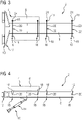
- FIG 2 is also a side view, in 3 a top view and in FIG 4 a front view of this seat unit 2 is shown.
- the seat unit can, for example, be a seat unit for a mobile unit, in particular for a rail vehicle.
- the seat unit 2 has a seat 4 .
- the seat 4 comprises a seat surface element 6.
- the seat 4 can also have other elements which are not shown here for the sake of clarity.
- the seat is in the Figures 1 to 4 only indicated by dashed lines, so that the other elements of the seat unit 2 are visible.
- the seat unit has a support arm 8 .
- the support arm 8 is an endless profile brought to length, in particular a lengthened, roll-formed endless profile.
- the support arm 8 is in one piece.
- the support arm 8 is designed as a cantilever support arm. This means that the support arm is designed to be attached exclusively to a side wall of the mobile unit.
- the seat unit 2 includes a means 10 for fastening the support arm 8 to the side wall of the mobile unit.
- the means 10 for fastening the Support arm 8 includes a wall bracket 12 and a bracket 14. Using the means 10 for attaching the support arm 8, the support arm 8 can be attached to a side wall of the mobile unit.
- the seat 4 is attached to the support arm 8 using support members 16 .
- the seat 4 is attached to the support arm 8 using two support members 16 .
- the seat unit 2 comprises these two support elements 16.
- Each of the support elements 16 comprises at least one seat attachment element 18, by means of which the respective support element 16 is firmly connected to the seat 4.
- the support elements 16 are arranged in such a way that the seat attachment elements 18 are arranged outside of the support arm 8 .
- each of the support elements 16 comprises two seat attachment elements 18.
- Each of the support elements 16 has two opposite ends in its longitudinal direction.
- the two seat attachment members 18 of each support member 16 are disposed at opposite ends of the respective support member 16, respectively.
- each of the support elements 16 in this exemplary embodiment has a rib 20 that can be inserted.
- Each of the insertable ribs 20 is at least partially inserted into the support arm 8 .
- the support arm 8 has several cutouts 22 .
- the recesses 22 are slot-shaped. In particular, the recesses 22 run in the transverse direction of the support arm 8.
- Each of the support elements 16 is partially inserted into at least one of the recesses 22 in each case.
- the insertable rib 20 is in each case at least partially inserted, in particular inserted, into at least one of the recesses 22 .
- the longitudinal direction of the respective support element 16 runs in each case essentially parallel to a transverse direction of the support arm 8.
- the transverse direction of the support arm 8 and the longitudinal direction of the support arm 8 are perpendicular to one another. Furthermore, the transverse direction runs essentially horizontally.
- the seat 4 is immovable relative to the support arm 8 using the support members 16. This means that the seat 4 cannot be moved relative to the support arm 8 using the support members 16.
- each of the seat fastening elements 18 comprises a threaded bore 24.
- Each of the seat fastening elements 18 is connected to the seat 4 via the respective threaded bore 24 using a screw connection.
- each of the support elements 16 is connected to the support arm 8 using a welded connection.
- the respective rib 20 is connected to the respective at least one recess 22, into which the respective rib 20 is inserted, by connecting a welded joint.
- each rib 20 is connected to each two seat attachment elements 18 using a welded connection.
- the seat 4 is spaced from the support arm 8 using the support members 16 .
- the seat attachment elements 18 are spaced from the support arm 8 in this exemplary embodiment.
- the seat fastening elements 18 are spaced apart from the support arm in the transverse direction of the support arm 8 (cf. 3 ).
- the seat unit 2 has two further support elements 16 .
- a further seat (not shown) could be connected to the support arm 8 via the two further support elements 16 .
- All support elements 16 of the seat unit 2 are preferably identical in structure to one another, as shown in this exemplary embodiment.
- the support elements 16 can be freely positioned on the support arm 8, depending on where the recesses 22 are made.
- the seat fastening elements 18 can be freely positioned relative to the support arm 8 . In this way, the seat 4 can also be freely positioned. In addition, the seat 4 can be freely selected in this way.
- FIG 5 and 6 show another seat unit 26.
- FIG 5 a three-dimensional view and 6 a front view of the seat unit 26.
- the seat 4 is connected to the support arm 8 via four support elements 16 .
- Each of the support members 16 includes a rib 20 and a single seat attachment member 18.
- the support member 16 is formed such that the seat 4 partially rests on a surface of the support arm 8. As shown in FIG.
- the seat unit 26 comprises these four support elements 16.
- the seat unit 26 comprises four further support elements 16.
- a further seat (not shown) could be connected to the support arm 8 using the four further support elements 16.
Landscapes
- Engineering & Computer Science (AREA)
- Mechanical Engineering (AREA)
- Aviation & Aerospace Engineering (AREA)
- Transportation (AREA)
- Seats For Vehicles (AREA)
- Fittings On The Vehicle Exterior For Carrying Loads, And Devices For Holding Or Mounting Articles (AREA)
- Motorcycle And Bicycle Frame (AREA)
- Automatic Cycles, And Cycles In General (AREA)
- Air Bags (AREA)
Priority Applications (2)
| Application Number | Priority Date | Filing Date | Title |
|---|---|---|---|
| HRP20220959TT HRP20220959T1 (hr) | 2017-11-02 | 2018-10-10 | Jedinstveni sklop za sjedenje i mobilni sklop |
| RS20220756A RS63494B1 (sr) | 2017-11-02 | 2018-10-10 | Jedinica za sedište i mobilna jedinica |
Applications Claiming Priority (2)
| Application Number | Priority Date | Filing Date | Title |
|---|---|---|---|
| DE102017219485.5A DE102017219485A1 (de) | 2017-11-02 | 2017-11-02 | Sitzeinheit und mobile Einheit |
| PCT/EP2018/077544 WO2019086217A1 (de) | 2017-11-02 | 2018-10-10 | Sitzeinheit und mobile einheit |
Publications (2)
| Publication Number | Publication Date |
|---|---|
| EP3676150A1 EP3676150A1 (de) | 2020-07-08 |
| EP3676150B1 true EP3676150B1 (de) | 2022-06-01 |
Family
ID=64023980
Family Applications (1)
| Application Number | Title | Priority Date | Filing Date |
|---|---|---|---|
| EP18793573.9A Active EP3676150B1 (de) | 2017-11-02 | 2018-10-10 | Sitzeinheit und mobile einheit |
Country Status (10)
| Country | Link |
|---|---|
| EP (1) | EP3676150B1 (pl) |
| CN (1) | CN213705436U (pl) |
| DE (1) | DE102017219485A1 (pl) |
| ES (1) | ES2924884T3 (pl) |
| HR (1) | HRP20220959T1 (pl) |
| PL (1) | PL3676150T3 (pl) |
| PT (1) | PT3676150T (pl) |
| RS (1) | RS63494B1 (pl) |
| RU (1) | RU201516U1 (pl) |
| WO (1) | WO2019086217A1 (pl) |
Cited By (4)
| Publication number | Priority date | Publication date | Assignee | Title |
|---|---|---|---|---|
| DE102023211302A1 (de) * | 2023-11-14 | 2025-05-15 | Siemens Mobility GmbH | Sitzanordnung |
| EP4667281A1 (en) * | 2024-06-19 | 2025-12-24 | F.I.S.A. - Fabbrica Italiana Sedili Autoferroviari - S.r.l. | Support device for at least one seat of road-rail vehicles for public transport and method for producing and installing it |
| EP4674681A1 (de) | 2024-07-02 | 2026-01-07 | Siemens Mobility GmbH | Sitzanordnung |
| DE102024207662A1 (de) | 2024-08-12 | 2026-02-12 | Siemens Mobility GmbH | Sitzanordnung |
Family Cites Families (8)
| Publication number | Priority date | Publication date | Assignee | Title |
|---|---|---|---|---|
| CA1020854A (en) * | 1975-04-10 | 1977-11-15 | Otaco Limited | Transportation seating construction and system |
| DE19526840A1 (de) * | 1995-07-22 | 1997-01-23 | Gunnar Kolb | Untergestell für einen Fahrgastsitz |
| DE10126404C2 (de) * | 2001-05-22 | 2003-08-21 | Daimlerchrysler Rail Systems | Sitzbefestigung |
| US7434877B2 (en) * | 2005-09-23 | 2008-10-14 | American Seating Company | Transportation seating system |
| EP1864855A1 (de) * | 2006-06-09 | 2007-12-12 | Schlegel Ag | Sitzträger |
| RU110693U1 (ru) * | 2011-02-16 | 2011-11-27 | Сименс Акциенгезелльшафт | Сиденье транспортного средства, в частности пассажирское сиденье в транспортном средстве для перевозки пассажиров |
| DE102012207446A1 (de) | 2012-05-04 | 2013-11-07 | Siemens Aktiengesellschaft | Cantilever-Sitzträger |
| DE202014103167U1 (de) * | 2014-07-10 | 2014-07-25 | Borcad Cz S.R.O. | Befestigungssystem von Sitzen eines Verkehrsmittels |
-
2017
- 2017-11-02 DE DE102017219485.5A patent/DE102017219485A1/de not_active Ceased
-
2018
- 2018-10-10 CN CN201890001328.7U patent/CN213705436U/zh active Active
- 2018-10-10 EP EP18793573.9A patent/EP3676150B1/de active Active
- 2018-10-10 PT PT187935739T patent/PT3676150T/pt unknown
- 2018-10-10 WO PCT/EP2018/077544 patent/WO2019086217A1/de not_active Ceased
- 2018-10-10 HR HRP20220959TT patent/HRP20220959T1/hr unknown
- 2018-10-10 RU RU2020114499U patent/RU201516U1/ru active
- 2018-10-10 ES ES18793573T patent/ES2924884T3/es active Active
- 2018-10-10 RS RS20220756A patent/RS63494B1/sr unknown
- 2018-10-10 PL PL18793573.9T patent/PL3676150T3/pl unknown
Cited By (7)
| Publication number | Priority date | Publication date | Assignee | Title |
|---|---|---|---|---|
| DE102023211302A1 (de) * | 2023-11-14 | 2025-05-15 | Siemens Mobility GmbH | Sitzanordnung |
| WO2025103653A1 (de) | 2023-11-14 | 2025-05-22 | Siemens Mobility GmbH | Sitzanordnung |
| EP4667281A1 (en) * | 2024-06-19 | 2025-12-24 | F.I.S.A. - Fabbrica Italiana Sedili Autoferroviari - S.r.l. | Support device for at least one seat of road-rail vehicles for public transport and method for producing and installing it |
| EP4674681A1 (de) | 2024-07-02 | 2026-01-07 | Siemens Mobility GmbH | Sitzanordnung |
| DE102024206178A1 (de) | 2024-07-02 | 2026-01-08 | Siemens Mobility GmbH | Sitzanordnung |
| DE102024207662A1 (de) | 2024-08-12 | 2026-02-12 | Siemens Mobility GmbH | Sitzanordnung |
| EP4696551A1 (de) | 2024-08-12 | 2026-02-18 | Siemens Mobility GmbH | Sitzanordnung |
Also Published As
| Publication number | Publication date |
|---|---|
| HRP20220959T1 (hr) | 2022-10-28 |
| DE102017219485A1 (de) | 2019-05-02 |
| CN213705436U (zh) | 2021-07-16 |
| RU201516U1 (ru) | 2020-12-18 |
| EP3676150A1 (de) | 2020-07-08 |
| ES2924884T3 (es) | 2022-10-11 |
| WO2019086217A1 (de) | 2019-05-09 |
| RS63494B1 (sr) | 2022-09-30 |
| PL3676150T3 (pl) | 2022-09-26 |
| PT3676150T (pt) | 2022-07-25 |
Similar Documents
| Publication | Publication Date | Title |
|---|---|---|
| DE102005042403B3 (de) | Modulares Sitzsystem für ein Fahrzeug | |
| DE102009020199B4 (de) | Bausatz füt Sitzreihen in Flugzeugen | |
| EP3676150B1 (de) | Sitzeinheit und mobile einheit | |
| DE102014202697B4 (de) | Sitzwinkel-Einstellmechanismus und damit ausgestatteter Kindersitz | |
| EP2252508B1 (de) | Vorrichtung zur lösbaren bodenbefestigung von schränken oder dergleichen in bordküchen von flugzeugen | |
| DE102009048894B4 (de) | System zur Befestigung eines Sitzes, insbesondere eines Luftfahrzeugs, und ein solches System aufweisender Sitz | |
| DE102015117709A1 (de) | Adapterschienensystem und Verfahren zum Befestigen eines Objekts an einer Fußbodenschiene in einem Transportmittel | |
| DE102009028533B4 (de) | Befestigungssystem in einem Luft- und Raumfahrzeug | |
| DE102016111999A1 (de) | Modulares Schienensystem mit Klemmbefestigung | |
| EP2569838A2 (de) | Kabelbefestigungsvorrichtung | |
| DE2828477A1 (de) | Konsole fuer einen fahrzeugsitz | |
| DE4304456C2 (de) | Anordnung mit einer längsverschiebbaren Schiene und einem daran befestigten Anschlag | |
| DE102016111983B4 (de) | Modulares Schienensystem | |
| EP2948339A1 (de) | Befestigungsanordnung für ein innenausstattungselement am wagenkasten eines fahrzeugs | |
| DE102016111994A1 (de) | Modulares Schienensystem | |
| EP1845219B1 (de) | Tragvorrichtung für Wandverkleidungen | |
| DE102016114479A1 (de) | Frachtrückhaltesystem für Flugzeuge | |
| EP3461963B1 (de) | Trägersystem und system von verbindungselementen zur verbindung von trägern | |
| DE2426900A1 (de) | Feststellvorrichtung fuer eine fuehrungsanordnung eines gleitend einstellbaren sitzes in einem motorfahrzeug | |
| EP2508106B1 (de) | Trag- und Montageprofilen zur Fixierung von Paneelen in einem Ladenbausystem | |
| EP2283748A1 (de) | Trägersystem | |
| EP1820729B1 (de) | Flugzeugsitzbefestigungsvorrichtung | |
| DE102005044322A1 (de) | Haltekonstruktion für Fassadenplatten | |
| EP1876053A2 (de) | Fahrgastsitz | |
| EP3017741B1 (de) | Halte-, stütz- oder sitzanordnung |
Legal Events
| Date | Code | Title | Description |
|---|---|---|---|
| REG | Reference to a national code |
Ref country code: HR Ref legal event code: TUEP Ref document number: P20220959 Country of ref document: HR |
|
| STAA | Information on the status of an ep patent application or granted ep patent |
Free format text: STATUS: UNKNOWN |
|
| STAA | Information on the status of an ep patent application or granted ep patent |
Free format text: STATUS: THE INTERNATIONAL PUBLICATION HAS BEEN MADE |
|
| PUAI | Public reference made under article 153(3) epc to a published international application that has entered the european phase |
Free format text: ORIGINAL CODE: 0009012 |
|
| STAA | Information on the status of an ep patent application or granted ep patent |
Free format text: STATUS: REQUEST FOR EXAMINATION WAS MADE |
|
| 17P | Request for examination filed |
Effective date: 20200403 |
|
| AK | Designated contracting states |
Kind code of ref document: A1 Designated state(s): AL AT BE BG CH CY CZ DE DK EE ES FI FR GB GR HR HU IE IS IT LI LT LU LV MC MK MT NL NO PL PT RO RS SE SI SK SM TR |
|
| AX | Request for extension of the european patent |
Extension state: BA ME |
|
| DAV | Request for validation of the european patent (deleted) | ||
| DAX | Request for extension of the european patent (deleted) | ||
| GRAP | Despatch of communication of intention to grant a patent |
Free format text: ORIGINAL CODE: EPIDOSNIGR1 |
|
| STAA | Information on the status of an ep patent application or granted ep patent |
Free format text: STATUS: GRANT OF PATENT IS INTENDED |
|
| INTG | Intention to grant announced |
Effective date: 20220215 |
|
| GRAS | Grant fee paid |
Free format text: ORIGINAL CODE: EPIDOSNIGR3 |
|
| GRAA | (expected) grant |
Free format text: ORIGINAL CODE: 0009210 |
|
| STAA | Information on the status of an ep patent application or granted ep patent |
Free format text: STATUS: THE PATENT HAS BEEN GRANTED |
|
| AK | Designated contracting states |
Kind code of ref document: B1 Designated state(s): AL AT BE BG CH CY CZ DE DK EE ES FI FR GB GR HR HU IE IS IT LI LT LU LV MC MK MT NL NO PL PT RO RS SE SI SK SM TR |
|
| REG | Reference to a national code |
Ref country code: GB Ref legal event code: FG4D Free format text: NOT ENGLISH |
|
| REG | Reference to a national code |
Ref country code: AT Ref legal event code: REF Ref document number: 1495203 Country of ref document: AT Kind code of ref document: T Effective date: 20220615 Ref country code: CH Ref legal event code: EP |
|
| REG | Reference to a national code |
Ref country code: IE Ref legal event code: FG4D Free format text: LANGUAGE OF EP DOCUMENT: GERMAN |
|
| REG | Reference to a national code |
Ref country code: DE Ref legal event code: R096 Ref document number: 502018009830 Country of ref document: DE |
|
| REG | Reference to a national code |
Ref country code: PT Ref legal event code: SC4A Ref document number: 3676150 Country of ref document: PT Date of ref document: 20220725 Kind code of ref document: T Free format text: AVAILABILITY OF NATIONAL TRANSLATION Effective date: 20220719 |
|
| REG | Reference to a national code |
Ref country code: LT Ref legal event code: MG9D |
|
| REG | Reference to a national code |
Ref country code: NL Ref legal event code: MP Effective date: 20220601 |
|
| REG | Reference to a national code |
Ref country code: ES Ref legal event code: FG2A Ref document number: 2924884 Country of ref document: ES Kind code of ref document: T3 Effective date: 20221011 |
|
| REG | Reference to a national code |
Ref country code: HR Ref legal event code: T1PR Ref document number: P20220959 Country of ref document: HR Ref country code: HR Ref legal event code: ODRP Ref document number: P20220959 Country of ref document: HR Payment date: 20221005 Year of fee payment: 5 |
|
| PG25 | Lapsed in a contracting state [announced via postgrant information from national office to epo] |
Ref country code: SE Free format text: LAPSE BECAUSE OF FAILURE TO SUBMIT A TRANSLATION OF THE DESCRIPTION OR TO PAY THE FEE WITHIN THE PRESCRIBED TIME-LIMIT Effective date: 20220601 Ref country code: NO Free format text: LAPSE BECAUSE OF FAILURE TO SUBMIT A TRANSLATION OF THE DESCRIPTION OR TO PAY THE FEE WITHIN THE PRESCRIBED TIME-LIMIT Effective date: 20220901 Ref country code: LT Free format text: LAPSE BECAUSE OF FAILURE TO SUBMIT A TRANSLATION OF THE DESCRIPTION OR TO PAY THE FEE WITHIN THE PRESCRIBED TIME-LIMIT Effective date: 20220601 Ref country code: GR Free format text: LAPSE BECAUSE OF FAILURE TO SUBMIT A TRANSLATION OF THE DESCRIPTION OR TO PAY THE FEE WITHIN THE PRESCRIBED TIME-LIMIT Effective date: 20220902 Ref country code: FI Free format text: LAPSE BECAUSE OF FAILURE TO SUBMIT A TRANSLATION OF THE DESCRIPTION OR TO PAY THE FEE WITHIN THE PRESCRIBED TIME-LIMIT Effective date: 20220601 |
|
| PG25 | Lapsed in a contracting state [announced via postgrant information from national office to epo] |
Ref country code: LV Free format text: LAPSE BECAUSE OF FAILURE TO SUBMIT A TRANSLATION OF THE DESCRIPTION OR TO PAY THE FEE WITHIN THE PRESCRIBED TIME-LIMIT Effective date: 20220601 |
|
| PG25 | Lapsed in a contracting state [announced via postgrant information from national office to epo] |
Ref country code: NL Free format text: LAPSE BECAUSE OF FAILURE TO SUBMIT A TRANSLATION OF THE DESCRIPTION OR TO PAY THE FEE WITHIN THE PRESCRIBED TIME-LIMIT Effective date: 20220601 |
|
| PG25 | Lapsed in a contracting state [announced via postgrant information from national office to epo] |
Ref country code: SM Free format text: LAPSE BECAUSE OF FAILURE TO SUBMIT A TRANSLATION OF THE DESCRIPTION OR TO PAY THE FEE WITHIN THE PRESCRIBED TIME-LIMIT Effective date: 20220601 Ref country code: SK Free format text: LAPSE BECAUSE OF FAILURE TO SUBMIT A TRANSLATION OF THE DESCRIPTION OR TO PAY THE FEE WITHIN THE PRESCRIBED TIME-LIMIT Effective date: 20220601 Ref country code: RO Free format text: LAPSE BECAUSE OF FAILURE TO SUBMIT A TRANSLATION OF THE DESCRIPTION OR TO PAY THE FEE WITHIN THE PRESCRIBED TIME-LIMIT Effective date: 20220601 Ref country code: EE Free format text: LAPSE BECAUSE OF FAILURE TO SUBMIT A TRANSLATION OF THE DESCRIPTION OR TO PAY THE FEE WITHIN THE PRESCRIBED TIME-LIMIT Effective date: 20220601 |
|
| PG25 | Lapsed in a contracting state [announced via postgrant information from national office to epo] |
Ref country code: IS Free format text: LAPSE BECAUSE OF FAILURE TO SUBMIT A TRANSLATION OF THE DESCRIPTION OR TO PAY THE FEE WITHIN THE PRESCRIBED TIME-LIMIT Effective date: 20221001 |
|
| REG | Reference to a national code |
Ref country code: DE Ref legal event code: R097 Ref document number: 502018009830 Country of ref document: DE |
|
| PG25 | Lapsed in a contracting state [announced via postgrant information from national office to epo] |
Ref country code: AL Free format text: LAPSE BECAUSE OF FAILURE TO SUBMIT A TRANSLATION OF THE DESCRIPTION OR TO PAY THE FEE WITHIN THE PRESCRIBED TIME-LIMIT Effective date: 20220601 |
|
| PLBE | No opposition filed within time limit |
Free format text: ORIGINAL CODE: 0009261 |
|
| STAA | Information on the status of an ep patent application or granted ep patent |
Free format text: STATUS: NO OPPOSITION FILED WITHIN TIME LIMIT |
|
| PG25 | Lapsed in a contracting state [announced via postgrant information from national office to epo] |
Ref country code: DK Free format text: LAPSE BECAUSE OF FAILURE TO SUBMIT A TRANSLATION OF THE DESCRIPTION OR TO PAY THE FEE WITHIN THE PRESCRIBED TIME-LIMIT Effective date: 20220601 |
|
| 26N | No opposition filed |
Effective date: 20230302 |
|
| PG25 | Lapsed in a contracting state [announced via postgrant information from national office to epo] |
Ref country code: SI Free format text: LAPSE BECAUSE OF FAILURE TO SUBMIT A TRANSLATION OF THE DESCRIPTION OR TO PAY THE FEE WITHIN THE PRESCRIBED TIME-LIMIT Effective date: 20220601 Ref country code: MC Free format text: LAPSE BECAUSE OF FAILURE TO SUBMIT A TRANSLATION OF THE DESCRIPTION OR TO PAY THE FEE WITHIN THE PRESCRIBED TIME-LIMIT Effective date: 20220601 |
|
| REG | Reference to a national code |
Ref country code: BE Ref legal event code: MM Effective date: 20221031 |
|
| PG25 | Lapsed in a contracting state [announced via postgrant information from national office to epo] |
Ref country code: LU Free format text: LAPSE BECAUSE OF NON-PAYMENT OF DUE FEES Effective date: 20221010 |
|
| PG25 | Lapsed in a contracting state [announced via postgrant information from national office to epo] |
Ref country code: BE Free format text: LAPSE BECAUSE OF NON-PAYMENT OF DUE FEES Effective date: 20221031 |
|
| REG | Reference to a national code |
Ref country code: HR Ref legal event code: ODRP Ref document number: P20220959 Country of ref document: HR Payment date: 20230928 Year of fee payment: 6 |
|
| PG25 | Lapsed in a contracting state [announced via postgrant information from national office to epo] |
Ref country code: IE Free format text: LAPSE BECAUSE OF NON-PAYMENT OF DUE FEES Effective date: 20221010 |
|
| PGFP | Annual fee paid to national office [announced via postgrant information from national office to epo] |
Ref country code: RS Payment date: 20230928 Year of fee payment: 6 Ref country code: PT Payment date: 20230925 Year of fee payment: 6 Ref country code: HR Payment date: 20230928 Year of fee payment: 6 |
|
| PGFP | Annual fee paid to national office [announced via postgrant information from national office to epo] |
Ref country code: BG Payment date: 20231020 Year of fee payment: 6 |
|
| PG25 | Lapsed in a contracting state [announced via postgrant information from national office to epo] |
Ref country code: HU Free format text: LAPSE BECAUSE OF FAILURE TO SUBMIT A TRANSLATION OF THE DESCRIPTION OR TO PAY THE FEE WITHIN THE PRESCRIBED TIME-LIMIT; INVALID AB INITIO Effective date: 20181010 |
|
| PG25 | Lapsed in a contracting state [announced via postgrant information from national office to epo] |
Ref country code: CY Free format text: LAPSE BECAUSE OF FAILURE TO SUBMIT A TRANSLATION OF THE DESCRIPTION OR TO PAY THE FEE WITHIN THE PRESCRIBED TIME-LIMIT Effective date: 20220601 |
|
| PG25 | Lapsed in a contracting state [announced via postgrant information from national office to epo] |
Ref country code: MK Free format text: LAPSE BECAUSE OF FAILURE TO SUBMIT A TRANSLATION OF THE DESCRIPTION OR TO PAY THE FEE WITHIN THE PRESCRIBED TIME-LIMIT Effective date: 20220601 |
|
| PG25 | Lapsed in a contracting state [announced via postgrant information from national office to epo] |
Ref country code: MT Free format text: LAPSE BECAUSE OF FAILURE TO SUBMIT A TRANSLATION OF THE DESCRIPTION OR TO PAY THE FEE WITHIN THE PRESCRIBED TIME-LIMIT Effective date: 20220601 |
|
| PGFP | Annual fee paid to national office [announced via postgrant information from national office to epo] |
Ref country code: CH Payment date: 20250114 Year of fee payment: 7 |
|
| REG | Reference to a national code |
Ref country code: HR Ref legal event code: PBON Ref document number: P20220959 Country of ref document: HR Effective date: 20241010 |
|
| PG25 | Lapsed in a contracting state [announced via postgrant information from national office to epo] |
Ref country code: RS Free format text: LAPSE BECAUSE OF NON-PAYMENT OF DUE FEES Effective date: 20241010 |
|
| PG25 | Lapsed in a contracting state [announced via postgrant information from national office to epo] |
Ref country code: HR Free format text: LAPSE BECAUSE OF NON-PAYMENT OF DUE FEES Effective date: 20241010 |
|
| PG25 | Lapsed in a contracting state [announced via postgrant information from national office to epo] |
Ref country code: PT Free format text: LAPSE BECAUSE OF NON-PAYMENT OF DUE FEES Effective date: 20250410 |
|
| PG25 | Lapsed in a contracting state [announced via postgrant information from national office to epo] |
Ref country code: BG Free format text: LAPSE BECAUSE OF NON-PAYMENT OF DUE FEES Effective date: 20241010 |
|
| REG | Reference to a national code |
Ref country code: DE Ref legal event code: R081 Ref document number: 502018009830 Country of ref document: DE Owner name: SIEMENS MOBILITY GMBH, DE Free format text: FORMER OWNER: SIEMENS MOBILITY GMBH, 81739 MUENCHEN, DE |
|
| PG25 | Lapsed in a contracting state [announced via postgrant information from national office to epo] |
Ref country code: TR Free format text: LAPSE BECAUSE OF FAILURE TO SUBMIT A TRANSLATION OF THE DESCRIPTION OR TO PAY THE FEE WITHIN THE PRESCRIBED TIME-LIMIT Effective date: 20220601 |
|
| PGFP | Annual fee paid to national office [announced via postgrant information from national office to epo] |
Ref country code: GB Payment date: 20251111 Year of fee payment: 8 |
|
| PGFP | Annual fee paid to national office [announced via postgrant information from national office to epo] |
Ref country code: AT Payment date: 20250905 Year of fee payment: 8 |
|
| PGFP | Annual fee paid to national office [announced via postgrant information from national office to epo] |
Ref country code: IT Payment date: 20251027 Year of fee payment: 8 |
|
| REG | Reference to a national code |
Ref country code: CH Ref legal event code: U11 Free format text: ST27 STATUS EVENT CODE: U-0-0-U10-U11 (AS PROVIDED BY THE NATIONAL OFFICE) Effective date: 20260114 |
|
| PGFP | Annual fee paid to national office [announced via postgrant information from national office to epo] |
Ref country code: FR Payment date: 20251020 Year of fee payment: 8 |
|
| PGFP | Annual fee paid to national office [announced via postgrant information from national office to epo] |
Ref country code: CZ Payment date: 20251002 Year of fee payment: 8 |
|
| PGFP | Annual fee paid to national office [announced via postgrant information from national office to epo] |
Ref country code: PL Payment date: 20251002 Year of fee payment: 8 |
|
| PGFP | Annual fee paid to national office [announced via postgrant information from national office to epo] |
Ref country code: ES Payment date: 20260119 Year of fee payment: 8 |
|
| PGFP | Annual fee paid to national office [announced via postgrant information from national office to epo] |
Ref country code: DE Payment date: 20251219 Year of fee payment: 8 |