EP3676144B1 - Electromechanical brake caliper with two actuators compensating for uneven pad wear - Google Patents
Electromechanical brake caliper with two actuators compensating for uneven pad wear Download PDFInfo
- Publication number
- EP3676144B1 EP3676144B1 EP18819195.1A EP18819195A EP3676144B1 EP 3676144 B1 EP3676144 B1 EP 3676144B1 EP 18819195 A EP18819195 A EP 18819195A EP 3676144 B1 EP3676144 B1 EP 3676144B1
- Authority
- EP
- European Patent Office
- Prior art keywords
- actuator
- sleeve
- rotation
- pad
- longitudinal direction
- Prior art date
- Legal status (The legal status is an assumption and is not a legal conclusion. Google has not performed a legal analysis and makes no representation as to the accuracy of the status listed.)
- Active
Links
- 230000005540 biological transmission Effects 0.000 claims description 22
- 238000006243 chemical reaction Methods 0.000 claims description 4
- 238000004804 winding Methods 0.000 claims description 3
- 238000006073 displacement reaction Methods 0.000 description 5
- 230000001747 exhibiting effect Effects 0.000 description 3
- 208000035126 Facies Diseases 0.000 description 1
- 239000000969 carrier Substances 0.000 description 1
- 230000002301 combined effect Effects 0.000 description 1
- 230000000295 complement effect Effects 0.000 description 1
- 235000021189 garnishes Nutrition 0.000 description 1
Images


Classifications
-
- B—PERFORMING OPERATIONS; TRANSPORTING
- B60—VEHICLES IN GENERAL
- B60T—VEHICLE BRAKE CONTROL SYSTEMS OR PARTS THEREOF; BRAKE CONTROL SYSTEMS OR PARTS THEREOF, IN GENERAL; ARRANGEMENT OF BRAKING ELEMENTS ON VEHICLES IN GENERAL; PORTABLE DEVICES FOR PREVENTING UNWANTED MOVEMENT OF VEHICLES; VEHICLE MODIFICATIONS TO FACILITATE COOLING OF BRAKES
- B60T13/00—Transmitting braking action from initiating means to ultimate brake actuator with power assistance or drive; Brake systems incorporating such transmitting means, e.g. air-pressure brake systems
- B60T13/74—Transmitting braking action from initiating means to ultimate brake actuator with power assistance or drive; Brake systems incorporating such transmitting means, e.g. air-pressure brake systems with electrical assistance or drive
- B60T13/746—Transmitting braking action from initiating means to ultimate brake actuator with power assistance or drive; Brake systems incorporating such transmitting means, e.g. air-pressure brake systems with electrical assistance or drive and mechanical transmission of the braking action
-
- F—MECHANICAL ENGINEERING; LIGHTING; HEATING; WEAPONS; BLASTING
- F16—ENGINEERING ELEMENTS AND UNITS; GENERAL MEASURES FOR PRODUCING AND MAINTAINING EFFECTIVE FUNCTIONING OF MACHINES OR INSTALLATIONS; THERMAL INSULATION IN GENERAL
- F16D—COUPLINGS FOR TRANSMITTING ROTATION; CLUTCHES; BRAKES
- F16D65/00—Parts or details
- F16D65/14—Actuating mechanisms for brakes; Means for initiating operation at a predetermined position
- F16D65/16—Actuating mechanisms for brakes; Means for initiating operation at a predetermined position arranged in or on the brake
- F16D65/18—Actuating mechanisms for brakes; Means for initiating operation at a predetermined position arranged in or on the brake adapted for drawing members together, e.g. for disc brakes
- F16D65/183—Actuating mechanisms for brakes; Means for initiating operation at a predetermined position arranged in or on the brake adapted for drawing members together, e.g. for disc brakes with force-transmitting members arranged side by side acting on a spot type force-applying member
-
- B—PERFORMING OPERATIONS; TRANSPORTING
- B60—VEHICLES IN GENERAL
- B60T—VEHICLE BRAKE CONTROL SYSTEMS OR PARTS THEREOF; BRAKE CONTROL SYSTEMS OR PARTS THEREOF, IN GENERAL; ARRANGEMENT OF BRAKING ELEMENTS ON VEHICLES IN GENERAL; PORTABLE DEVICES FOR PREVENTING UNWANTED MOVEMENT OF VEHICLES; VEHICLE MODIFICATIONS TO FACILITATE COOLING OF BRAKES
- B60T1/00—Arrangements of braking elements, i.e. of those parts where braking effect occurs specially for vehicles
- B60T1/02—Arrangements of braking elements, i.e. of those parts where braking effect occurs specially for vehicles acting by retarding wheels
- B60T1/06—Arrangements of braking elements, i.e. of those parts where braking effect occurs specially for vehicles acting by retarding wheels acting otherwise than on tread, e.g. employing rim, drum, disc, or transmission or on double wheels
- B60T1/065—Arrangements of braking elements, i.e. of those parts where braking effect occurs specially for vehicles acting by retarding wheels acting otherwise than on tread, e.g. employing rim, drum, disc, or transmission or on double wheels employing disc
-
- B—PERFORMING OPERATIONS; TRANSPORTING
- B60—VEHICLES IN GENERAL
- B60T—VEHICLE BRAKE CONTROL SYSTEMS OR PARTS THEREOF; BRAKE CONTROL SYSTEMS OR PARTS THEREOF, IN GENERAL; ARRANGEMENT OF BRAKING ELEMENTS ON VEHICLES IN GENERAL; PORTABLE DEVICES FOR PREVENTING UNWANTED MOVEMENT OF VEHICLES; VEHICLE MODIFICATIONS TO FACILITATE COOLING OF BRAKES
- B60T13/00—Transmitting braking action from initiating means to ultimate brake actuator with power assistance or drive; Brake systems incorporating such transmitting means, e.g. air-pressure brake systems
- B60T13/74—Transmitting braking action from initiating means to ultimate brake actuator with power assistance or drive; Brake systems incorporating such transmitting means, e.g. air-pressure brake systems with electrical assistance or drive
- B60T13/741—Transmitting braking action from initiating means to ultimate brake actuator with power assistance or drive; Brake systems incorporating such transmitting means, e.g. air-pressure brake systems with electrical assistance or drive acting on an ultimate actuator
-
- F—MECHANICAL ENGINEERING; LIGHTING; HEATING; WEAPONS; BLASTING
- F16—ENGINEERING ELEMENTS AND UNITS; GENERAL MEASURES FOR PRODUCING AND MAINTAINING EFFECTIVE FUNCTIONING OF MACHINES OR INSTALLATIONS; THERMAL INSULATION IN GENERAL
- F16D—COUPLINGS FOR TRANSMITTING ROTATION; CLUTCHES; BRAKES
- F16D55/00—Brakes with substantially-radial braking surfaces pressed together in axial direction, e.g. disc brakes
- F16D55/02—Brakes with substantially-radial braking surfaces pressed together in axial direction, e.g. disc brakes with axially-movable discs or pads pressed against axially-located rotating members
- F16D55/22—Brakes with substantially-radial braking surfaces pressed together in axial direction, e.g. disc brakes with axially-movable discs or pads pressed against axially-located rotating members by clamping an axially-located rotating disc between movable braking members, e.g. movable brake discs or brake pads
- F16D55/224—Brakes with substantially-radial braking surfaces pressed together in axial direction, e.g. disc brakes with axially-movable discs or pads pressed against axially-located rotating members by clamping an axially-located rotating disc between movable braking members, e.g. movable brake discs or brake pads with a common actuating member for the braking members
- F16D55/225—Brakes with substantially-radial braking surfaces pressed together in axial direction, e.g. disc brakes with axially-movable discs or pads pressed against axially-located rotating members by clamping an axially-located rotating disc between movable braking members, e.g. movable brake discs or brake pads with a common actuating member for the braking members the braking members being brake pads
- F16D55/226—Brakes with substantially-radial braking surfaces pressed together in axial direction, e.g. disc brakes with axially-movable discs or pads pressed against axially-located rotating members by clamping an axially-located rotating disc between movable braking members, e.g. movable brake discs or brake pads with a common actuating member for the braking members the braking members being brake pads in which the common actuating member is moved axially, e.g. floating caliper disc brakes
-
- F—MECHANICAL ENGINEERING; LIGHTING; HEATING; WEAPONS; BLASTING
- F16—ENGINEERING ELEMENTS AND UNITS; GENERAL MEASURES FOR PRODUCING AND MAINTAINING EFFECTIVE FUNCTIONING OF MACHINES OR INSTALLATIONS; THERMAL INSULATION IN GENERAL
- F16D—COUPLINGS FOR TRANSMITTING ROTATION; CLUTCHES; BRAKES
- F16D65/00—Parts or details
- F16D65/38—Slack adjusters
- F16D65/40—Slack adjusters mechanical
- F16D65/62—Slack adjusters mechanical self-acting in both directions for adjusting excessive and insufficient play
-
- F—MECHANICAL ENGINEERING; LIGHTING; HEATING; WEAPONS; BLASTING
- F16—ENGINEERING ELEMENTS AND UNITS; GENERAL MEASURES FOR PRODUCING AND MAINTAINING EFFECTIVE FUNCTIONING OF MACHINES OR INSTALLATIONS; THERMAL INSULATION IN GENERAL
- F16D—COUPLINGS FOR TRANSMITTING ROTATION; CLUTCHES; BRAKES
- F16D2121/00—Type of actuator operation force
- F16D2121/18—Electric or magnetic
- F16D2121/24—Electric or magnetic using motors
-
- F—MECHANICAL ENGINEERING; LIGHTING; HEATING; WEAPONS; BLASTING
- F16—ENGINEERING ELEMENTS AND UNITS; GENERAL MEASURES FOR PRODUCING AND MAINTAINING EFFECTIVE FUNCTIONING OF MACHINES OR INSTALLATIONS; THERMAL INSULATION IN GENERAL
- F16D—COUPLINGS FOR TRANSMITTING ROTATION; CLUTCHES; BRAKES
- F16D2125/00—Components of actuators
- F16D2125/18—Mechanical mechanisms
- F16D2125/20—Mechanical mechanisms converting rotation to linear movement or vice versa
- F16D2125/34—Mechanical mechanisms converting rotation to linear movement or vice versa acting in the direction of the axis of rotation
- F16D2125/40—Screw-and-nut
-
- F—MECHANICAL ENGINEERING; LIGHTING; HEATING; WEAPONS; BLASTING
- F16—ENGINEERING ELEMENTS AND UNITS; GENERAL MEASURES FOR PRODUCING AND MAINTAINING EFFECTIVE FUNCTIONING OF MACHINES OR INSTALLATIONS; THERMAL INSULATION IN GENERAL
- F16D—COUPLINGS FOR TRANSMITTING ROTATION; CLUTCHES; BRAKES
- F16D2125/00—Components of actuators
- F16D2125/18—Mechanical mechanisms
- F16D2125/44—Mechanical mechanisms transmitting rotation
- F16D2125/46—Rotating members in mutual engagement
- F16D2125/48—Rotating members in mutual engagement with parallel stationary axes, e.g. spur gears
-
- F—MECHANICAL ENGINEERING; LIGHTING; HEATING; WEAPONS; BLASTING
- F16—ENGINEERING ELEMENTS AND UNITS; GENERAL MEASURES FOR PRODUCING AND MAINTAINING EFFECTIVE FUNCTIONING OF MACHINES OR INSTALLATIONS; THERMAL INSULATION IN GENERAL
- F16D—COUPLINGS FOR TRANSMITTING ROTATION; CLUTCHES; BRAKES
- F16D2125/00—Components of actuators
- F16D2125/18—Mechanical mechanisms
- F16D2125/44—Mechanical mechanisms transmitting rotation
- F16D2125/46—Rotating members in mutual engagement
- F16D2125/50—Rotating members in mutual engagement with parallel non-stationary axes, e.g. planetary gearing
-
- F—MECHANICAL ENGINEERING; LIGHTING; HEATING; WEAPONS; BLASTING
- F16—ENGINEERING ELEMENTS AND UNITS; GENERAL MEASURES FOR PRODUCING AND MAINTAINING EFFECTIVE FUNCTIONING OF MACHINES OR INSTALLATIONS; THERMAL INSULATION IN GENERAL
- F16D—COUPLINGS FOR TRANSMITTING ROTATION; CLUTCHES; BRAKES
- F16D2125/00—Components of actuators
- F16D2125/18—Mechanical mechanisms
- F16D2125/44—Mechanical mechanisms transmitting rotation
- F16D2125/46—Rotating members in mutual engagement
- F16D2125/52—Rotating members in mutual engagement with non-parallel stationary axes, e.g. worm or bevel gears
Definitions
- the invention relates to an electromechanical type motor vehicle disc brake caliper, that is to say equipped with an electric motor driving mechanical actuators.
- a hydraulic type disc brake caliper just as in an electromechanical type brake caliper, several actuators can be provided to jointly press a single pad against the disc when the brake is activated.
- the invention relates more particularly to a disc brake caliper comprising an electromechanical actuator including a first and a second mechanical actuator extending side by side facing a pad.
- the first actuator pushes a first wafer portion that is close to a first end of that wafer and the second actuator pushes a second wafer portion that is close to a second end of that wafer.
- a pad includes a support on which is fixed a friction lining intended only to come into friction with a face of the disc in order to brake it.
- the uneven thickness of the pad is compensated by the fact that the actuators which push it are connected to the same hydraulic circuit. With such a circuit, the operation corresponds to that of a force servo-control, which thereby allows the actuators to have displacements of different lengths.
- an electromechanical type caliper With an electromechanical type caliper, it is the same motor which drives the mechanical actuators pushing a pad, via a transmission mechanism so that they bring the pistons closer to the disk in order to press the pad.
- the object of the invention is to remedy this drawback by proposing a transmission mechanism which makes it possible to compensate for uneven wear of a pad, in an electromechanical type brake caliper with mechanical actuators driven by the same electric motor.
- the document FR3045757 A1 discloses a conventional electromechanical disc brake, fixed caliper comprising a transmission compensating asymmetric wear (right - left) of its pads.
- the invention also relates to a brake caliper thus defined, in which the internal splines protrude from a hub rigidly connected to the sleeve.
- the invention also relates to a brake caliper thus defined, in which the first and the second driving wheel are obliquely toothed and rotate about axes parallel to each other and perpendicular to the longitudinal direction.
- the invention also relates to a brake caliper thus defined, comprising a reduction module which transmits the rotation of the motor to the means for driving the first and second worm screws in rotation.
- the invention also relates to a disc brake comprising a brake caliper thus defined.
- a floating mounted caliper 1 comprises a caliper body 2 which carries a set of pads 3 and 4 on either side of a brake disc. braking 6, and which is equipped with an electromechanical actuator 7 for pressing these pads 3 and 4 against the disc 6 in braking situation.
- the plate 3 comprises a support 3a to which a lining 3b is attached.
- the plate 4 comprises a support 4a to which a lining 4b is attached.
- This electromechanical actuator 7 shown in figure 2 comprises an electric motor 13 which drives, via a drive mechanism 14, two mechanical actuators 8 and 9 arranged vis-à-vis the plate 3.
- This plate 3 extends laterally, that is to say which extends in a direction tangential to the disc 6.
- the two mechanical actuators 8 and 9 are side by side along the plate 3 extending perpendicularly to this one.
- the first actuator 8 is opposite a first portion of the plate 3 close to a first end of this plate 3 and the second mechanical actuator 9 is opposite a second portion of the plate 3 close to a second end of this plate 3.
- the first actuator 8 is mounted in a first cavity 11 of the caliper body 2 along an axis AX1 in an axial direction, that is to say in a direction normal to the brake disc 6, while the second actuator 9 is mounted in a second cavity of the caliper body 2 along an axis AX2 parallel to AX1.
- the first actuator 8 comprises a part included in the caliper body 2 with a first piston 8a which surrounds a first nut 8b screwed around a first axial driving screw 8c, and a part outside the caliper body 2 with a first helical-toothed drive wheel 8d, in other words oblique, which is rigidly secured to this first drive screw 8c.
- the first piston 8a and the first nut 8b are locked in rotation around the axis AX1 but movable in translation along this axis AX1 while the first driving screw 8c and the first driving wheel 8d are movable in rotation around the axis AX1 but blocked in translation along this same axis AX1.
- This arrangement converts a rotation of the first driving wheel 8d into an axial translation of the first piston 8a along the axis AX1, in one direction or the other depending on the direction of rotation of this first driving wheel 8d.
- the second actuator 9 comprises a second driving wheel 9d for moving a second piston 9a axially along AX2 by means of a second nut and a second driving screw, not shown.
- the first and second drive wheels 8d and 9d have reverse thread directions.
- the second actuator 9 thus converts the rotation of its driving wheel 9d into a translation of its piston 9a which is the reverse of the conversion provided by the first actuator 8. In other words, it is when the two driving wheels 8d and 9d rotate in opposite directions as the first and second piston 8a and 9a move in the same axial direction.
- the drive mechanism 14 comprises a transmission module 15 and a reduction module 16 which transmits a rotation of the motor 13, more precisely a rotation of a motor pinion 17 with oblique teeth driven directly by the motor, to the transmission module 15 with a speed lower than that of this motor pinion 17.
- the reduction module 16 comprises at input an intermediate wheel 18 with oblique toothing followed by an epicyclic gear train 19, with the intermediate wheel 18 meshed in the motor pinion 17 of axis AX3, parallel to the axes AX1 and AX2, to transmit its rotation to the epicyclic train 19.
- the epicyclic gear train 19 comprises an input sun gear 20, which is a toothed wheel with oblique teeth, in which the intermediate wheel 18 engages to make this input sun gear 20 rotate about an axis AX4 parallel to the axis AX3.
- the input sun gear 20 is extended along its axis of rotation AX4 by a planetary gear 21 with straight teeth, this sun gear 21 meshing three planet wheels 22.
- the planet wheels 22 are mounted to pivot around their axis of revolution on a planet carrier 23 mobile in rotation around the axis AX4. These satellites 22 are meshed in a fixed circular ring which surrounds them, this ring not being shown in the figures.
- the rotation of the input sun gear 20 allows the satellites 22 to rotate not only around their own axis but also with their respective axis around the axis AX4, rotating the planet carrier 23 at a speed of output much lower than the input speed.
- the planet carrier 23 is extended at the output of the epicyclic gear train 19 by an output pinion 24 with straight teeth, visible on the figure 4 , which protrudes from the center of the face of the planet carrier 23 opposite the planet wheels 22.
- the transmission module 15 comprises an angular gear wheel 26 rotating about an axis of longitudinal direction AY perpendicular to the axis AX4, this angular gear 26 being meshed in the output pinion 24.
- This arrangement converts the rotation of pinion 24 around axis AX4 into rotation of bevel gear 26 around axis AY which is perpendicular to it, otherwise called right angle transmission.
- the bevel wheel 26 has a central through hole along the axis AY which is splined to form a sliding connection of a rotary shaft 27, one end of which, which is splined in a corresponding manner, is slidably engaged in this hole.
- This sliding connection allows the angular gear 26 to drive the shaft 27 in rotation while allowing this shaft 27 to slide along AY.
- the shaft 27 extends along the axis AY in a plane parallel to the plane defined by the axes AX1 and AX2 and comprises a first and a second worm 28 and 29 which protrude fixedly from it, with the two screws endless 28 and 29 aligned along the axis AY.
- the first worm 28 is meshed with the first driving wheel 8d and the second worm 29 meshed with the second driving toothed wheel 9d.
- This arrangement converts the rotation of the shaft 27 around the axis AY into a rotation of the first and second drive wheels 8d and 9d around their respective axes AX1 and AX2, with the worms 28 and 29 integral with the shaft. 27. These rotations are in turn converted by the first and second mechanical actuators 8 and 9 in axial translation of their respective piston 8a and 9a.
- the two worm screws 28 and 29 have reverse winding directions so that a rotation of the shaft 27 in a direction marked by R on the figure 5 causes the exit of the two pistons 8a and 9a, the mechanical actuators 8 and 9 having opposite operating modes.
- a rotation of the shaft 27 in a direction opposite to the direction R causes on the contrary the retraction of the two pistons 8a and 9a.
- the portion of the plate 3 pressed here by the first actuator 8 comes to rest on the braking disc 6 before the portion pressed by the second actuator 9.
- the first piston 8a as well as the first driving wheel 8d come to a standstill , the brake disc 6 constituting an opposing force to the displacement of the portion of the pad 3 pressed by the first actuator 8.
- the motor 13 continuing to drive the shaft 27 in rotation, with the worms 28 and 29, it then causes the longitudinal translation of this shaft 27 along AY in a direction indicated by T.
- the second piston 9a bearing the portion of the plate which is not yet in contact with the disc 6 continues to progress under the combined effect of the rotation of the shaft 27 and of its translation, given that the first and second worm 28 and 29 are meshed respectively in the first and second driving wheels 8d and 9d, while the first driving wheel 8d is immobilized.
- the shaft 27 stops moving in translation but continues to rotate around its axis AY, thus allowing the force to be increased. simultaneous pads against the disc 6.
- the shaft 27 comes to a standstill once a desired torque of the drive wheels has been reached.
- a return to the initial state of the pad 3, ie to the state before braking, is allowed by a rotation of the shaft 27 but in the opposite direction to the direction R, with the same number of revolutions as those made during braking in the direction R, and a translation of the shaft in the opposite direction of T according to the same amplitude of initial displacement of T.
- the reverse rotation causes in the first place the retraction of the two pistons 8a and 9a until the piston 8a is fully retracted, then the shaft 27 moves in translation in the direction opposite to T, while retaining its rotation, until the piston 9a returns to the initial position.
- the caliper 1 makes it possible to compensate for uneven wear of the pad by associating a rotation of the worm screws with a sliding connection, ensuring that when a first portion of the pad 3 comes to rest on the disc 6, the other wafer portion can continue to move until it in turn comes to rest against the disc 6 with the desired force.
- the invention is not limited to the embodiment described of the transmission module 15 and allows the use of various and varied architectures provided that the worms are integral with one another in rotation with the toothed wheel. , and movable in translation with respect to the latter, that is to say linked to the wheel by a sliding connection.
- the rotary shaft 27' is fixed in translation by being rigidly integral with the angular gear wheel 26 ', and the worms 28' and 29 'are aligned and formed on a sleeve 31 separate from this shaft 27 '.
- the shaft 27 'and the sleeve 31 extend longitudinally along the axis AY, with the shaft 27' having external splines 32 along its extent, and the sleeve 31 surrounding this shaft 27 'and the external splines 32
- the transmission module 15 'further comprises a hub 33 extending between the shaft 27' and the sleeve 31 being rigidly linked to the sleeve 31 in its central region, that is to say between the worm screws. 28 'and 29'.
- the hub 33 is provided with internal splines 34 which engage in the external splines 32.
- the shaft 27 'and the sleeve 31, via the hub 33, are thus coupled in rotation while leaving the sleeve 31 which carries the screws 28 'and 29', a degree of freedom in translation along the axis AY with respect to the shaft 27 '.
- a return to the initial state of the plate 3 is allowed by a rotation of the assembly formed by the shaft 27 ', the hub 33 and the sleeve 31 but in the opposite direction to the direction indicated by R, with the same number of turns than those made during braking in the direction R.
- the reverse rotation first causes the retraction of the two pistons 8a and 9a until the piston 8a is fully retracted, then the sleeve 31 moves in translation in the direction opposite T, while maintaining its rotation, until the piston 9a returns to the initial position.
- the wafer portion pressed by the first actuator 8 has a lining of thickness less than that of the wafer portion pressed by the second actuator 9, but it should be noted that the invention does not only provide a solution to compensate this particular facies of wear.
- the invention could provide to do without the hub 33, with the internal splines 34 projecting directly from the sleeve 31 to engage in the external splines 32 of the shaft 27 ', thus limiting the number components of the transmission module 15 'and simplifying its assembly.
- the internal splines 34 are not necessarily formed in the central region of the sleeve 31, since they always comply with the functional condition of being meshed with the external splines 32 regardless of the state of wear of the lining. 3b.
- the invention could in particular provide that the external splines 32 do not extend over the entire extent of the shaft 27 ', since the maximum displacement of the sleeve 31 relative to the shaft 27' is limited by the two cases. for which one of the portions of garnish 3b is seine while the other portion is completely consumed.
- the shafts 27 and 27 are located “above” the first and second drive wheels 8d and 9d, with the axis AX1 located between the axes AX3 and AX4. But it should be noted that the invention could provide the shaft 27 or 27 'located “below” the driving wheels 8d and 9d, in other words with the axis AX4 closer to the axis of rotation of the brake disc. 6 than is AX1, to respect a different size.
Description
L'invention se rapporte à un étrier de frein à disque de véhicule automobile de type électromécanique, c'est-à-dire équipé d'un moteur électrique entraînant des actionneurs mécaniques.The invention relates to an electromechanical type motor vehicle disc brake caliper, that is to say equipped with an electric motor driving mechanical actuators.
Dans un étrier de frein à disque de type hydraulique, tout comme dans un étrier de frein de type électromécanique, plusieurs actionneurs peuvent être prévus pour presser conjointement une même plaquette contre le disque lorsque le frein est activé.In a hydraulic type disc brake caliper, just as in an electromechanical type brake caliper, several actuators can be provided to jointly press a single pad against the disc when the brake is activated.
L'invention se rapporte plus particulièrement à un étrier de frein à disque comportant un actionneur électromécanique incluant un premier et un second actionneurs mécaniques s'étendant côte à côte en vis-à-vis d'une plaquette. Le premier actionneur pousse une première portion de plaquette qui est proche d'une première extrémité de cette plaquette et le second actionneur pousse une seconde portion de plaquette qui est proche d'une seconde extrémité de cette plaquette.The invention relates more particularly to a disc brake caliper comprising an electromechanical actuator including a first and a second mechanical actuator extending side by side facing a pad. The first actuator pushes a first wafer portion that is close to a first end of that wafer and the second actuator pushes a second wafer portion that is close to a second end of that wafer.
Une plaquette inclut un support sur lequel est fixée une garniture de friction destinée seule à entrer en friction avec une face du disque afin de le freiner.A pad includes a support on which is fixed a friction lining intended only to come into friction with a face of the disc in order to brake it.
En pratique, il apparaît que de telles plaquettes s'usent de manière inégale, conduisant à une épaisseur de garniture qui se réduit d'une extrémité à l'autre extrémité de la plaquette.In practice, it appears that such pads wear unevenly, leading to a lining thickness which is reduced from one end to the other end of the pad.
Dans le cas d'un étrier hydraulique, l'épaisseur inégale de la plaquette est compensée par le fait que les actionneurs qui la poussent sont reliés à un même circuit hydraulique. Avec un tel circuit le fonctionnement correspond à celui d'un asservissement en efforts, qui permet par là même que les actionneurs aient des déplacements de longueurs différentes.In the case of a hydraulic caliper, the uneven thickness of the pad is compensated by the fact that the actuators which push it are connected to the same hydraulic circuit. With such a circuit, the operation corresponds to that of a force servo-control, which thereby allows the actuators to have displacements of different lengths.
Concrètement, lors du freinage, la mise sous pression du circuit hydraulique, et par là même des actionneurs hydrauliques, déplace les pistons de ces actionneurs vers le disque selon des déplacements pouvant être différents. Ces déplacements s'opèrent jusqu'à ce que les pistons plaquent la totalité de la plaquette contre le disque, la pression restant la même dans le circuit et dans les actionneurs en toutes circonstances.Concretely, during braking, the pressurization of the hydraulic circuit, and thereby of the hydraulic actuators, moves the pistons of these actuators towards the disc according to displacements which may be different. These movements take place until the pistons press the entire pad against the disc, the pressure remaining the same in the circuit and in the actuators under all circumstances.
Il s'ensuit qu'avec un étrier hydraulique, le rattrapage d'une usure inégale de la plaquette se fait de manière naturelle.It follows that with a hydraulic caliper, compensation for uneven pad wear occurs naturally.
Avec un étrier de type électromécanique, c'est un même moteur qui entraîne les actionneurs mécaniques poussant une plaquette, par l'intermédiaire d'un mécanisme de transmission pour qu'ils rapprochent les pistons du disque afin de presser la plaquette.With an electromechanical type caliper, it is the same motor which drives the mechanical actuators pushing a pad, via a transmission mechanism so that they bring the pistons closer to the disk in order to press the pad.
Si le mécanisme assure une transmission de type directe entre la rotation du moteur et la rotation des organes déplaçant les pistons, une inégalité d'épaisseur d'une plaquette ne peut pas être compensée car les déplacements et les positions de base des pistons sont nécessairement les mêmes.If the mechanism provides a direct type of transmission between the rotation of the engine and the rotation of the members moving the pistons, an unevenness in thickness of a pad cannot be compensated because the movements and the basic positions of the pistons are necessarily the same.
Concrètement, lors du freinage avec une telle transmission de type directe, dès lors qu'un actionneur plaque contre le disque la portion de plaquette qu'il pousse, l'effort presseur exercé sur le disque va à l'encontre du couple moteur : la rotation du moteur est bloquée et le mécanisme s'immobilise en interrompant la course de l'autre piston.Concretely, during braking with such a direct type transmission, as soon as an actuator presses the portion of the pad that it pushes against the disc, the pressing force exerted on the disc goes against the engine torque: the rotation of the motor is blocked and the mechanism is immobilized by interrupting the stroke of the other piston.
L'invention a pour objet de remédier à cet inconvénient en proposant un mécanisme de transmission qui permet de rattraper une usure inégale d'une plaquette, dans un étrier de frein de type électromécanique avec des actionneurs mécaniques entraînés par un même moteur électrique. Le document
A cet effet, l'invention a pour objet un étrier de frein destiné à chevaucher un disque de freinage, qui comprend un jeu de plaquettes et un actionneur électromécanique pour presser une plaquette contre une face du disque, caractérisé en ce que l'actionneur électromécanique comprend :
- un moteur électrique entraînant un premier actionneur mécanique et un second actionneur mécanique ;
- le premier actionneur mécanique incluant une première roue entraîneuse dentée et un premier piston pour presser une première portion de la plaquette ;
- le second actionneur mécanique incluant une seconde roue entraîneuse dentée et un second piston mobile pour presser une seconde portion de la plaquette ;
- chaque actionneur convertissant une rotation de sa roue entraîneuse en une translation de son piston, le premier et le second actionneur ayant des sens de conversion inverses ;
- un module de transmission comprenant :
- une première vis sans fin et une seconde vis sans fin de même direction longitudinale et ayant des sens d'enroulement inverses tout en étant rigidement solidaires l'une de l'autre, ces première et seconde vis sans fin étant engrenées respectivement avec la première et la seconde roue entraîneuses pour les faire tourner simultanément en sens inverses ;
- des moyens d'entraînement en rotation des première et seconde vis sans fin par le moteur électrique, ces moyens formant une liaison glissière permettant à la première et la seconde vis sans fin de se déplacer en translation suivant la direction longitudinale.
- an electric motor driving a first mechanical actuator and a second mechanical actuator;
- the first mechanical actuator including a first toothed drive wheel and a first piston for pressing a first portion of the pad;
- the second mechanical actuator including a second toothed drive wheel and a second movable piston for pressing a second portion of the pad;
- each actuator converting a rotation of its driving wheel into a translation of its piston, the first and the second actuator having opposite directions of conversion;
- a transmission module comprising:
- a first worm and a second worm having the same longitudinal direction and having reverse winding directions while being rigidly integral with one another, these first and second worms being meshed respectively with the first and the second driving wheel to rotate them simultaneously in opposite directions;
- means for rotating the first and second worm screws by the electric motor, these means forming a sliding connection allowing the first and the second worm screw to move in translation in the longitudinal direction.
Avec cette solution, lorsqu'une portion de plaquette arrive au contact du disque, la roue entraîneuse de l'actionneur correspondante s'immobilise, mais les vis sans fin continuent de tourner en se translatant pour déplacer le piston de l'actionneur associé à l'autre partie de la plaquette. Le mécanisme compense ainsi une usure inégale de la plaquette en assurant que cette plaquette soit entièrement pressée contre le disque lors du freinage.With this solution, when a portion of the pad comes into contact with the disc, the driving wheel of the corresponding actuator comes to a standstill, but the worms continue to turn while moving to move the piston of the actuator associated with the disc. other part of the blister pack. The mechanism thus compensates for uneven wear brake pad ensuring that this pad is fully pressed against the disc when braking.
L'invention concerne également un étrier de frein ainsi défini, dans lequel les moyens formant liaison glissière et d'entraînement en rotation des vis sans fin du module de transmission comportent :
- un arbre rotatif portant rigidement les première et seconde vis sans fin, cet arbre étant mobile en translation suivant la direction longitudinale ;
- une roue dentée fixe en translation et mise en rotation par le moteur électrique, cette roue dentée comprenant un trou traversant cannelé dans lequel une extrémité cannelée de l'arbre est engagée.
- a rotary shaft rigidly supporting the first and second worm screws, this shaft being movable in translation in the longitudinal direction;
- a toothed wheel fixed in translation and rotated by the electric motor, this toothed wheel comprising a splined through hole in which a splined end of the shaft is engaged.
L'invention concerne également un étrier de frein ainsi défini, dans lequel les moyens formant liaison glissière et d'entraînement en rotation des vis sans fin du module de transmission comportent :
- un manchon portant rigidement les première et seconde vis sans fin, ce manchon étant mobile en translation suivant la direction longitudinale ;
- une roue dentée fixe en translation et mise en rotation par le moteur électrique ;
- un arbre rotatif qui est solidaire rigidement et dépasse de la roue dentée en comportant des cannelures externes, cet arbre rotatif s'étendant suivant la direction longitudinale en étant entouré du manchon ;
- des cannelures internes portées par le manchon avec lesquelles les cannelures externes s'engrènent par complémentarité de forme.
- a sleeve rigidly supporting the first and second worm screws, this sleeve being movable in translation in the longitudinal direction;
- a toothed wheel fixed in translation and rotated by the electric motor;
- a rotary shaft which is rigidly attached to and protrudes from the toothed wheel by comprising external splines, this rotary shaft extending in the longitudinal direction while being surrounded by the sleeve;
- internal grooves carried by the sleeve with which the external grooves mesh by complementary shape.
L'invention concerne également un étrier de frein ainsi défini, dans lequel les cannelures internes dépassent d'un moyeu lié rigidement au manchon.The invention also relates to a brake caliper thus defined, in which the internal splines protrude from a hub rigidly connected to the sleeve.
L'invention concerne également un étrier de frein ainsi défini, dans lequel la première et la seconde roue entraîneuse sont à denture oblique et tournent autour d'axes parallèles l'un à l'autre et perpendiculaires à la direction longitudinale.The invention also relates to a brake caliper thus defined, in which the first and the second driving wheel are obliquely toothed and rotate about axes parallel to each other and perpendicular to the longitudinal direction.
L'invention concerne également un étrier de frein ainsi défini, comprenant un module de réduction qui transmet la rotation du moteur au moyens d'entraînement en rotation des première et seconde vis sans fin.The invention also relates to a brake caliper thus defined, comprising a reduction module which transmits the rotation of the motor to the means for driving the first and second worm screws in rotation.
L'invention concerne également un frein à disque comprenant un étrier de frein ainsi défini.The invention also relates to a disc brake comprising a brake caliper thus defined.
-
la
figure 1 est une vue en coupe d'un étrier de frein à disque selon l'invention selon un plan de coupe traversant longitudinalement le premier actionneur mécanique ;thefigure 1 is a sectional view of a disc brake caliper according to the invention according to a section plane longitudinally crossing the first mechanical actuator; -
la
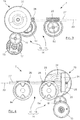
figure 2 est une vue en perspective de l'actionneur électromécanique selon l'invention ;thefigure 2 is a perspective view of the electromechanical actuator according to the invention; -
la
figure 3 est une vue de face de l'actionneur électromécanique selon l'invention ;thefigure 3 is a front view of the electromechanical actuator according to the invention; -
la
figure 4 est une vue arrière de l'actionneur électromécanique selon l'invention montrant notamment la configuration du réducteur épicycloïdal ;thefigure 4 is a rear view of the electromechanical actuator according to the invention showing in particular the configuration of the epicyclic reduction gear; -
la
figure 5 est une vue de dessus de l'actionneur électromécanique selon l'invention en situation de freinage avec une plaquette neuve ;thefigure 5 is a top view of the electromechanical actuator according to the invention in a braking situation with a new pad; -
la
figure 6 est une vue de dessus de l'actionneur électromécanique selon l'invention en situation de freinage avec une plaquette présentant une usure inégale ;thefigure 6 is a top view of the electromechanical actuator according to the invention in a braking situation with a pad exhibiting uneven wear; -
la
figure 7 est une vue de détail du module d'entraînement selon une variante de l'invention ;thefigure 7 is a detail view of the drive module according to a variant of the invention; -
la
figure 8 est une vue de dessus de l'actionneur électromécanique selon une variante de l'invention en situation de freinage avec une plaquette présentant une usure inégale.thefigure 8 is a top view of the electromechanical actuator according to a variant of the invention in a braking situation with a pad exhibiting uneven wear.
Comme visible sur la
La plaquette 3 comprend un support 3a auquel est fixée une garniture 3b. De la même manière, la plaquette 4 comprend un support 4a auquel est fixée une garniture 4b.The
Cet actionneur électromécanique 7 représenté en
Cette plaquette 3 s'étend latéralement, c'est-à-dire qui s'étend dans une direction tangentielle au disque 6. Les deux actionneurs mécaniques 8 et 9 sont côte à côte le long de la plaquette 3 en s'étendant perpendiculairement à celle-ci. Le premier actionneur 8 est en regard d'une première portion de la plaquette 3 proche d'une première extrémité de cette plaquette 3 et le second actionneur mécanique 9 est en regard d'une seconde portion de la plaquette 3 proche d'une seconde extrémité de cette plaquette 3. Le premier actionneur 8 est monté dans une première cavité 11 du corps d'étrier 2 selon un axe AX1 dans une direction axiale, c'est à dire dans une direction normale au disque de freinage 6, tandis que le second actionneur 9 est monté dans une seconde cavité du corps d'étrier 2 selon un axe AX2 parallèle à AX1.This
Le premier actionneur 8 comprend une partie inclue dans le corps d'étrier 2 avec un premier piston 8a qui entoure un premier écrou 8b vissé autour d'une première vis entraîneuse 8c axiale, et une partie hors du corps d'étrier 2 avec une première roue entraîneuse 8d à denture hélicoïdale, autrement dit oblique, qui est rigidement solidaire de cette première vis entraîneuse 8c.The
Le premier piston 8a et le premier écrou 8b sont bloqués en rotation autour de l'axe AX1 mais mobiles en translation selon cet axe AX1 tandis que la première vis entraîneuse 8c et la première roue entraîneuse 8d sont mobiles en rotation autour de l'axe AX1 mais bloquées en translation selon ce même axe AX1.The
Cet agencement convertit une rotation de la première roue entraîneuse 8d en une translation axiale du premier piston 8a selon l'axe AX1, dans un sens ou dans l'autre en fonction du sens de rotation de cette première roue entraîneuse 8d.This arrangement converts a rotation of the
De manière analogue, le second actionneur 9 comporte une seconde roue entraîneuse 9d pour déplacer un second piston 9a axialement selon AX2 par l'intermédiaire d'un second écrou et d'une seconde vis entraîneuse non représentés.Similarly, the
Les première et seconde roues entraîneuses 8d et 9d ont des sens de filet inverses. Le second actionneur 9 assure ainsi une conversion de la rotation de sa roue entraîneuse 9d en une translation de son piston 9a qui est inverse de la conversion assurée par le premier actionneur 8. Autrement dit, c'est lorsque les deux roues entraîneuses 8d et 9d tournent dans des sens inverses que le premier et le second piston 8a et 9a se déplacement dans le même sens axial.The first and
Le mécanisme d'entraînement 14 comprend un module de transmission 15 et un module de réduction 16 qui transmet une rotation du moteur 13, plus précisément une rotation d'un pignon moteur 17 à denture oblique entraîné directement par le moteur, au module de transmission 15 avec une vitesse inférieure à celle de ce pignon moteur 17.The
Le module de réduction 16 comprend en entrée une roue intermédiaire 18 à denture oblique suivit d'un train épicycloïdal 19, avec la roue intermédiaire 18 engrenée dans le pignon moteur 17 d'axe AX3, parallèle aux axes AX1 et AX2, pour transmettre sa rotation au train épicycloïdal 19.The
Comme visible sur la
Avec cet agencement, la rotation du planétaire d'entré 20 permet aux satellites 22 de tourner non seulement autour de leur propre axe mais aussi avec leur axe respectif autour de l'axe AX4, mettant en rotation le porte-satellites 23 à une vitesse de sortie très inférieure à la vitesse d'entrée.With this arrangement, the rotation of the
Le porte-satellites 23 est prolongé en sortie du train épicycloïdal 19 par un pignon de sortie 24 à denture droite, visible sur la
Le module de transmission 15 comporte une roue dentée à renvoi d'angle 26 tournant autour d'un axe de direction longitudinale AY perpendiculaire à l'axe AX4, cette roue à renvoi d'angle 26 étant engrenée dans le pignon de sortie 24.The
Cet agencement convertit la rotation du pignon 24 autour de l'axe AX4 en une rotation de la roue à renvoi d'angle 26 autour de l'axe AY qui lui est perpendiculaire, autrement appelée transmission à angle droit.This arrangement converts the rotation of
La roue à renvoi d'angle 26 présente un trou central traversant suivant l'axe AY qui est cannelé pour former une liaison glissière d'un arbre rotatif 27 dont une extrémité, qui est cannelée de manière correspondante, est engagée glissante dans ce trou. Cette liaison glissière permet à la roue à renvoi d'angle 26 d'entraîner l'arbre 27 en rotation tout en permettant à cet arbre 27 de coulisser suivant AY.The
L'arbre 27 s'étend suivant l'axe AY dans un plan parallèle au plan défini par les axes AX1 et AX2 et comporte une première et une seconde vis sans fin 28 et 29 qui dépassent fixement de celui-ci, avec les deux vis sans fin 28 et 29 alignées suivant l'axe AY. La première vis sans fin 28 est engrenée dans la première roue entraîneuse 8d et la seconde vis sans fin 29 engrenée dans la seconde roue dentée entraîneuse 9d.The
Cet agencement convertit la rotation de l'arbre 27 autour de l'axe AY en une rotation des première et seconde roues entraîneuses 8d et 9d autour de leurs axes respectifs AX1 et AX2, avec les vis sans fin 28 et 29 solidaires de l'arbre 27. Ces rotations sont à leur tour converties par les premier et second actionneurs mécanique 8 et 9 en translation axiale de leur piston 8a et 9a respectif.This arrangement converts the rotation of the
Les deux vis sans fin 28 et 29 ont des sens d'enroulement inverses de sorte qu'une rotation de l'arbre 27 dans un sens repéré par R sur la
En situation de freinage avec une plaquette 3 d'épaisseur constante comme sur l'exemple de la
En situation de freinage avec une plaquette 3 présentant une usure inégale comme sur la
Le moteur 13 continuant d'entraîner en rotation l'arbre 27, avec les vis sans fin 28 et 29, il provoque alors la translation longitudinale de cet arbre 27 suivant AY dans un sens repéré par T. Dans ces conditions, le second piston 9a portant la portion de plaquette qui n'est pas encore en contact avec le disque 6 continue de progresser sous l'effet conjugué de la rotation de l'arbre 27 et de sa translation, attendu que les première et seconde vis sans fin 28 et 29 sont engrenées respectivement dans les première et seconde roues entraîneuses 8d et 9d, tandis que la première roue entraîneuse 8d est immobilisée.The
Dès lors que la portion de plaquette associée au second actionneur 9 arrive en appui contre le disque 6, l'arbre 27 cesse de se déplacer en translation mais continue de tourner autour de son axe AY en permettant ainsi la montée en effort simultanée des plaquettes contre le disque 6. L'arbre 27 s'immobilise une fois un couple des roues entraîneuses souhaité atteint.As soon as the portion of the plate associated with the
Un retour à l'état initial de la plaquette 3, i.e. à l'état avant freinage, est permis par une rotation de l'arbre 27 mais en sens inverse au sens R, avec le même nombre de tours que ceux réalisés pendant le freinage dans le sens R, et une translation de l'arbre dans le sens opposé de T selon la même amplitude de déplacement initial de T. La rotation inverse provoque en premier lieu la rétractation des deux pistons 8a et 9a jusqu'à ce que le piston 8a soit entièrement rétracté, puis l'arbre 27 se déplace en translation dans le sens opposé à T, tout en conservant sa rotation, jusqu'à ce que le piston 9a revienne en position initiale.A return to the initial state of the
D'une manière générale, l'étrier 1 selon l'invention permet de rattraper une usure inégale de la plaquette en associant une rotation des vis sans fins avec une liaison glissière, assurant que lorsqu'une première portion de plaquette 3 arrive en appui sur le disque 6, l'autre portion de plaquette peut continuer à se déplacer jusqu'à arriver à son tour en appui contre le disque 6 avec la force désirée.In general, the caliper 1 according to the invention makes it possible to compensate for uneven wear of the pad by associating a rotation of the worm screws with a sliding connection, ensuring that when a first portion of the
L'invention ne se limite pas au mode de réalisation décrit du module de transmission 15 et permet l'utilisation d'architectures diverses et variées dès lors que les vis sans fins sont solidaires l'une de l'autre en rotation avec la roue dentée, et mobiles en translation par rapport à celle-ci, c'est-à-dire liées à la roue par une liaison glissière.The invention is not limited to the embodiment described of the
Aussi, dans la variante de la
Le moyeu 33 est pourvu de cannelures internes 34 qui s'engagent dans les cannelures externes 32. L'arbre 27' et le manchon 31, par l'intermédiaire du moyeu 33, sont ainsi couplés en rotation tout en laissant au manchon 31 qui porte les vis 28' et 29', un degré de liberté en translation suivant l'axe AY par rapport à l'arbre 27'.The
Avec cet arrangement, en situation de freinage illustrée à la
Un retour à l'état initial de la plaquette 3 est permis par une rotation de l'ensemble formé par l'arbre 27', le moyeu 33 et le manchon 31 mais en sens inverse au sens repéré par R, avec le même nombre de tours que ceux réalisés pendant le freinage dans le sens R. La rotation inverse provoque en premier lieu la rétractation des deux pistons 8a et 9a jusqu'à ce que le piston 8a soit entièrement rétracté, puis le manchon 31 se déplace en translation dans le sens opposé à T, tout en conservant sa rotation, jusqu'à ce que le piston 9a revienne en position initiale.A return to the initial state of the
Dans l'exemple des
En effet à l'inverse, dans le cas où la portion de plaquette pressée par le premier actionneur 8 présente une garniture d'épaisseur cette fois supérieure à celle de la portion de plaquette pressée par le second actionneur 9, les vis sans fins 28 et 29 ou 28' et 29' se déplacent dans le sens opposé à T lors d'une commande de freinage.In fact, conversely, in the case where the portion of the wafer pressed by the
Il est à noter également, que l'invention pourrait prévoir de s'affranchir du moyeu 33, avec les cannelures internes 34 dépassant directement du manchon 31 pour s'engrener dans les cannelures externe 32 de l'arbre 27', limitant ainsi le nombre de composants du module de transmission 15' et simplifiant son assemblage.It should also be noted that the invention could provide to do without the
En outre, les cannelures internes 34 ne sont pas nécessairement formées en région centrale du manchon 31, dès lors qu'elles respectent toujours la condition fonctionnelle d'être engrenées dans les cannelures externes 32 quel que soit l'état d'usure de la garniture 3b. L'invention pourrait notamment prévoir que les cannelures externes 32 ne s'étendent pas sur toute l'étendue de l'arbre 27', attendu que le déplacement maximum du manchon 31 par rapport à l'arbre 27' est borné par les deux cas pour lesquels une des portions de garniture 3b est seine tandis que l'autre portion est complètement consommée.In addition, the
Dans l'ensemble des figures, les arbres 27 et 27' sont situés « au-dessus » des première et seconde roues entraîneuses 8d et 9d, avec l'axe AX1 situé entre les axes AX3 et AX4. Mais il est à noter que l'invention pourrait prévoir l'arbre 27 ou 27' situé « au-dessous » des roues entraîneuses 8d et 9d, autrement dit avec l'axe AX4 plus proche de l'axe de rotation du disque de freinage 6 que ne l'est AX1, pour respecter un encombrement différent.In all of the figures, the
Dans la description ci-dessus, le fonctionnement du frein selon l'invention a été expliqué en termes de déplacement de ses composants afin d'en faciliter la compréhension. En pratique, dans le cas d'un freinage avec un tel actionneur les déplacements sont infimes et ce mécanisme convertit un couple exercé par le moteur 13 en un effort presseur exercé par chacun des pistons 8a et 9a sur la plaquette 3.In the above description, the operation of the brake according to the invention has been explained in terms of the movement of its components in order to facilitate understanding. In practice, in the case of braking with such an actuator, the movements are tiny and this mechanism converts a torque exerted by the
Claims (7)
- A brake caliper (1) for overlapping a brake disc (6), which comprises a set of pads (3, 4) and an electromechanical actuator (7) for pressing a pad (3) against a face of the disc (6), characterised in that the electromechanical actuator (7) comprises:- an electric motor (13) driving a first mechanical actuator (8) and a second mechanical actuator (9);- the first mechanical actuator (8) including a first drive gear (8d) and a first piston (8a) for pressing a first portion of the pad (3);- the second mechanical actuator (9) including a second drive gear (9d) and a second movable piston (9a) for pressing a second portion of the pad;- each actuator (8; 9) converting a rotation of its drive gear (8d; 9d) into a translation of its piston (8a; 9a), the first and second actuator having reverse conversion senses;- a transmission module (15; 15') comprising:- a first worm screw (28; 28') and a second worm screw (29; 29') having a same longitudinal direction (AY) and having reverse winding senses while being rigidly integral with each other, these first and second worm screws (28, 29; 28', 29') being meshed with the first and second drive gears (8d, 9d) respectively to simultaneously rotate them in reverse senses;- means for rotatably driving the first and second worm screws (28, 29; 28', 29') by the electric motor (13), these means forming a slide connection enabling the first and the second worms (28, 29; 28', 29') to translationally move along the longitudinal direction (AY).
- The caliper according to claim 1, wherein the means forming a slide connection and for rotatably driving the worm screws (28, 29) of the transmission module (15) include:- a rotary shaft (27) rigidly carrying the first and second worm screws (28, 29), this shaft being translationally movable along the longitudinal direction (AY);- a translationally fixed gear (26) rotated by the electric motor (13), this gear comprising a splined through hole in which a splined end of the shaft (27) is engaged.
- The caliper according to claim 1, wherein the means forming a slide connection and for rotatably driving the worm screws (28', 29') of the transmission module (15') include:- a sleeve (31) rigidly carrying the first and second worm screws (28', 29'), this sleeve (31) being translationally movable along the longitudinal direction (AY);- a translationally fixed gear (26') rotated by the electric motor (13);- a rotary shaft (27) which is rigidly integral with and project from the gear by including external splines (32), this rotary shaft (27) extending along the longitudinal direction (AY) by being surrounded by the sleeve (31);- internal splines (34) carried by the sleeve (31) with which the external splines (32) mesh by form fitting.
- The caliper according to claim 3, wherein the internal splines (34) project from a hub (33) rigidly connected to the sleeve (31).
- The caliper according to one of claims 1 to 4, wherein the first and second drive gears (8d, 9d) have oblique teeth and rotate about axes parallel to each other and perpendicular to the longitudinal direction (AY).
- The caliper according to one of the preceding claims, comprising a reduction module (16) which transmits rotation of the motor (13) to the means for rotatably driving the first and second worm screws (28; 29 / 28'; 29').
- A disc brake, comprising a caliper (1) according to one of the preceding claims.
Applications Claiming Priority (2)
| Application Number | Priority Date | Filing Date | Title |
|---|---|---|---|
| FR1761163A FR3074243B1 (en) | 2017-11-24 | 2017-11-24 | ELECTROMECHANICAL DISC BRAKE CALIPER COMPRISING TWO MECHANICAL ACTUATORS TO COMPENSATE FOR UNEQUAL WEAR OF THE SAME PAD |
| PCT/FR2018/052920 WO2019102133A1 (en) | 2017-11-24 | 2018-11-20 | Electromechanical-type disc brake caliper comprising two mechanical actuators to compensate for uneven wearing of the one same brake pad |
Publications (2)
| Publication Number | Publication Date |
|---|---|
| EP3676144A1 EP3676144A1 (en) | 2020-07-08 |
| EP3676144B1 true EP3676144B1 (en) | 2021-06-30 |
Family
ID=60765955
Family Applications (1)
| Application Number | Title | Priority Date | Filing Date |
|---|---|---|---|
| EP18819195.1A Active EP3676144B1 (en) | 2017-11-24 | 2018-11-20 | Electromechanical brake caliper with two actuators compensating for uneven pad wear |
Country Status (4)
| Country | Link |
|---|---|
| US (1) | US11535225B2 (en) |
| EP (1) | EP3676144B1 (en) |
| FR (1) | FR3074243B1 (en) |
| WO (1) | WO2019102133A1 (en) |
Families Citing this family (10)
| Publication number | Priority date | Publication date | Assignee | Title |
|---|---|---|---|---|
| KR20210009239A (en) * | 2019-07-16 | 2021-01-26 | 현대모비스 주식회사 | Parking brake apparatus for vehicle |
| DE102020118808A1 (en) * | 2019-07-16 | 2021-01-21 | Hyundai Mobis Co., Ltd. | Parking brake device for a vehicle |
| KR102644871B1 (en) * | 2019-07-16 | 2024-03-07 | 현대모비스 주식회사 | Parking brake apparatus for vehicle |
| US11420606B2 (en) * | 2019-07-16 | 2022-08-23 | Hyundai Mobis Co., Ltd. | Parking brake apparatus for vehicle |
| KR20210009241A (en) * | 2019-07-16 | 2021-01-26 | 현대모비스 주식회사 | Parking brake apparatus for vehicle |
| CN112298126B (en) * | 2019-08-01 | 2024-04-16 | 汉拿万都株式会社 | Vehicle caliper, vehicle braking method and vehicle |
| KR20210142793A (en) * | 2020-05-18 | 2021-11-26 | 현대자동차주식회사 | Electric braking booster for autonomous driving vehicle composed of dual actuator |
| CN114655177A (en) * | 2020-12-23 | 2022-06-24 | 沃尔沃汽车公司 | Motor vehicle brake system and method for operating same |
| CN113790231B (en) * | 2021-11-13 | 2022-02-11 | 杭州丹佛斯科技有限公司 | Abrasionproof decreases new energy automobile brake mechanism |
| FR3130002B1 (en) * | 2021-12-03 | 2023-10-27 | Hitachi Astemo France | Safe disengagement braking system |
Family Cites Families (8)
| Publication number | Priority date | Publication date | Assignee | Title |
|---|---|---|---|---|
| US9353811B2 (en) * | 2013-11-13 | 2016-05-31 | Akebono Brake Industry Co., Ltd | Electric park brake for a multiple piston caliper |
| FR3033378B1 (en) | 2015-03-06 | 2018-08-10 | Foundation Brakes France | "DISC BRAKE COMPRISING AT LEAST ONE ELASTIC RECALL SPRING OF A BRAKE SKATE, ELASTIC RECALL SPRING, GUIDE SLIDER AND REPLACEMENT KIT" |
| US9587692B2 (en) * | 2015-04-01 | 2017-03-07 | Akebono Brake Industry Co., Ltd | Differential for a parking brake assembly |
| FR3045757B1 (en) * | 2015-12-21 | 2018-06-29 | Foundation Brakes France | ELECTROMECHANICAL DISC BRAKE COMPRISING A TRANSMISSION COMPRISING AN ASYMMETRICAL WEAR OF ITS PLATES |
| FR3045758B1 (en) | 2015-12-21 | 2018-01-05 | Foundation Brakes France | ELECTROMECHANICAL DISK BRAKE COMPRISING A TRANSMISSION COMPRISING AN UNEQUAL WEAR OF THE SAME WAFER |
| US9989114B2 (en) * | 2016-06-24 | 2018-06-05 | Akebono Brake Industry Co., Ltd | Power transfer mechanism for a parking brake assembly |
| KR102022403B1 (en) * | 2018-01-17 | 2019-09-18 | 현대모비스 주식회사 | Brake apparatus for vehicle |
| KR20210049481A (en) * | 2019-10-25 | 2021-05-06 | 현대모비스 주식회사 | Parking brake apparatus for vehicle |
-
2017
- 2017-11-24 FR FR1761163A patent/FR3074243B1/en active Active
-
2018
- 2018-11-20 EP EP18819195.1A patent/EP3676144B1/en active Active
- 2018-11-20 US US16/766,377 patent/US11535225B2/en active Active
- 2018-11-20 WO PCT/FR2018/052920 patent/WO2019102133A1/en unknown
Also Published As
| Publication number | Publication date |
|---|---|
| EP3676144A1 (en) | 2020-07-08 |
| US20200361437A1 (en) | 2020-11-19 |
| WO2019102133A1 (en) | 2019-05-31 |
| US11535225B2 (en) | 2022-12-27 |
| FR3074243A1 (en) | 2019-05-31 |
| FR3074243B1 (en) | 2019-12-27 |
Similar Documents
| Publication | Publication Date | Title |
|---|---|---|
| EP3676144B1 (en) | Electromechanical brake caliper with two actuators compensating for uneven pad wear | |
| EP3089901B1 (en) | Motor-reducer with planetary gearset, drum and disc brake and braking device provided with same | |
| EP3089899B1 (en) | Actuator driven by a gear having an axial guide rail, and drum brake and braking device provided with same | |
| EP3394464B1 (en) | Electromechanical disk brake with fixed caliper comprising a transmission compensating asymmetric wear of the pads thereof | |
| FR2999673A1 (en) | "SATELLITE CARRIERS FOR AN ELECTROMECHANICAL PARKING BRAKE ACTUATOR, ACTUATOR AND ASSEMBLY METHODS" | |
| EP3175146B1 (en) | Torque reducer | |
| EP3175136B1 (en) | Vehicle brake actuator | |
| EP3394463B1 (en) | Electromechanical disk brake comprising a transmission compensating unequal wear on the same pad | |
| FR3015409A1 (en) | IMPROVED DISK BRAKE COMPRISING A HYDRAULICALLY ACTUATED PARKING BRAKE AND A WEAR TURNING GROUP | |
| EP3089900B1 (en) | Motor-reducer with electric motor for drum brake actuator | |
| EP3087286B1 (en) | Disk brake comprising a parking brake having hydraulic actuation | |
| FR3097605A1 (en) | Dual actuator brake caliper, disc brake and associated braking method | |
| EP3902727A1 (en) | Reduction motor for drum brake | |
| EP3087289B1 (en) | Improved disk brake comprising a hydraulic actuation parking brake | |
| FR3097021A1 (en) | REDUCER AND GEAR MOTOR FOR BRAKE WITH INTEGRATED CLUTCH | |
| EP3087288B1 (en) | Hydraulic control disk brake comprising a hydraulic actuation parking brake | |
| WO2020244936A1 (en) | Gear motor for drum brake actuator, comprising a step-down rate of 30 to 210 | |
| EP3087287B1 (en) | Disk brake comprising a hydraulic actuation parking brake and a wear adjustment unit | |
| FR2880083A1 (en) | Bearing assembly for column shaft activation system, has annular space delimited by two machines each having three parts, where radial dimensions of rear and front spaces are lesser than radius and diameter of balls, respectively |
Legal Events
| Date | Code | Title | Description |
|---|---|---|---|
| STAA | Information on the status of an ep patent application or granted ep patent |
Free format text: STATUS: UNKNOWN |
|
| STAA | Information on the status of an ep patent application or granted ep patent |
Free format text: STATUS: THE INTERNATIONAL PUBLICATION HAS BEEN MADE |
|
| PUAI | Public reference made under article 153(3) epc to a published international application that has entered the european phase |
Free format text: ORIGINAL CODE: 0009012 |
|
| STAA | Information on the status of an ep patent application or granted ep patent |
Free format text: STATUS: REQUEST FOR EXAMINATION WAS MADE |
|
| 17P | Request for examination filed |
Effective date: 20200403 |
|
| AK | Designated contracting states |
Kind code of ref document: A1 Designated state(s): AL AT BE BG CH CY CZ DE DK EE ES FI FR GB GR HR HU IE IS IT LI LT LU LV MC MK MT NL NO PL PT RO RS SE SI SK SM TR |
|
| AX | Request for extension of the european patent |
Extension state: BA ME |
|
| RIN1 | Information on inventor provided before grant (corrected) |
Inventor name: MOUMANE, MEHDI Inventor name: LABARRE, XAVIER Inventor name: ESNEE, DIDIER |
|
| GRAP | Despatch of communication of intention to grant a patent |
Free format text: ORIGINAL CODE: EPIDOSNIGR1 |
|
| STAA | Information on the status of an ep patent application or granted ep patent |
Free format text: STATUS: GRANT OF PATENT IS INTENDED |
|
| INTG | Intention to grant announced |
Effective date: 20210122 |
|
| DAV | Request for validation of the european patent (deleted) | ||
| DAX | Request for extension of the european patent (deleted) | ||
| GRAS | Grant fee paid |
Free format text: ORIGINAL CODE: EPIDOSNIGR3 |
|
| GRAA | (expected) grant |
Free format text: ORIGINAL CODE: 0009210 |
|
| STAA | Information on the status of an ep patent application or granted ep patent |
Free format text: STATUS: THE PATENT HAS BEEN GRANTED |
|
| AK | Designated contracting states |
Kind code of ref document: B1 Designated state(s): AL AT BE BG CH CY CZ DE DK EE ES FI FR GB GR HR HU IE IS IT LI LT LU LV MC MK MT NL NO PL PT RO RS SE SI SK SM TR |
|
| REG | Reference to a national code |
Ref country code: CH Ref legal event code: EP |
|
| REG | Reference to a national code |
Ref country code: DE Ref legal event code: R096 Ref document number: 602018019501 Country of ref document: DE Ref country code: AT Ref legal event code: REF Ref document number: 1406102 Country of ref document: AT Kind code of ref document: T Effective date: 20210715 |
|
| REG | Reference to a national code |
Ref country code: IE Ref legal event code: FG4D Free format text: LANGUAGE OF EP DOCUMENT: FRENCH |
|
| REG | Reference to a national code |
Ref country code: LT Ref legal event code: MG9D |
|
| RAP4 | Party data changed (patent owner data changed or rights of a patent transferred) |
Owner name: HITACHI ASTEMO FRANCE |
|
| PG25 | Lapsed in a contracting state [announced via postgrant information from national office to epo] |
Ref country code: FI Free format text: LAPSE BECAUSE OF FAILURE TO SUBMIT A TRANSLATION OF THE DESCRIPTION OR TO PAY THE FEE WITHIN THE PRESCRIBED TIME-LIMIT Effective date: 20210630 Ref country code: HR Free format text: LAPSE BECAUSE OF FAILURE TO SUBMIT A TRANSLATION OF THE DESCRIPTION OR TO PAY THE FEE WITHIN THE PRESCRIBED TIME-LIMIT Effective date: 20210630 Ref country code: BG Free format text: LAPSE BECAUSE OF FAILURE TO SUBMIT A TRANSLATION OF THE DESCRIPTION OR TO PAY THE FEE WITHIN THE PRESCRIBED TIME-LIMIT Effective date: 20210930 |
|
| REG | Reference to a national code |
Ref country code: NL Ref legal event code: MP Effective date: 20210630 |
|
| REG | Reference to a national code |
Ref country code: AT Ref legal event code: MK05 Ref document number: 1406102 Country of ref document: AT Kind code of ref document: T Effective date: 20210630 |
|
| PG25 | Lapsed in a contracting state [announced via postgrant information from national office to epo] |
Ref country code: GR Free format text: LAPSE BECAUSE OF FAILURE TO SUBMIT A TRANSLATION OF THE DESCRIPTION OR TO PAY THE FEE WITHIN THE PRESCRIBED TIME-LIMIT Effective date: 20211001 Ref country code: LV Free format text: LAPSE BECAUSE OF FAILURE TO SUBMIT A TRANSLATION OF THE DESCRIPTION OR TO PAY THE FEE WITHIN THE PRESCRIBED TIME-LIMIT Effective date: 20210630 Ref country code: NO Free format text: LAPSE BECAUSE OF FAILURE TO SUBMIT A TRANSLATION OF THE DESCRIPTION OR TO PAY THE FEE WITHIN THE PRESCRIBED TIME-LIMIT Effective date: 20210930 Ref country code: RS Free format text: LAPSE BECAUSE OF FAILURE TO SUBMIT A TRANSLATION OF THE DESCRIPTION OR TO PAY THE FEE WITHIN THE PRESCRIBED TIME-LIMIT Effective date: 20210630 Ref country code: SE Free format text: LAPSE BECAUSE OF FAILURE TO SUBMIT A TRANSLATION OF THE DESCRIPTION OR TO PAY THE FEE WITHIN THE PRESCRIBED TIME-LIMIT Effective date: 20210630 |
|
| PG25 | Lapsed in a contracting state [announced via postgrant information from national office to epo] |
Ref country code: SK Free format text: LAPSE BECAUSE OF FAILURE TO SUBMIT A TRANSLATION OF THE DESCRIPTION OR TO PAY THE FEE WITHIN THE PRESCRIBED TIME-LIMIT Effective date: 20210630 Ref country code: EE Free format text: LAPSE BECAUSE OF FAILURE TO SUBMIT A TRANSLATION OF THE DESCRIPTION OR TO PAY THE FEE WITHIN THE PRESCRIBED TIME-LIMIT Effective date: 20210630 Ref country code: ES Free format text: LAPSE BECAUSE OF FAILURE TO SUBMIT A TRANSLATION OF THE DESCRIPTION OR TO PAY THE FEE WITHIN THE PRESCRIBED TIME-LIMIT Effective date: 20210630 Ref country code: RO Free format text: LAPSE BECAUSE OF FAILURE TO SUBMIT A TRANSLATION OF THE DESCRIPTION OR TO PAY THE FEE WITHIN THE PRESCRIBED TIME-LIMIT Effective date: 20210630 Ref country code: NL Free format text: LAPSE BECAUSE OF FAILURE TO SUBMIT A TRANSLATION OF THE DESCRIPTION OR TO PAY THE FEE WITHIN THE PRESCRIBED TIME-LIMIT Effective date: 20210630 Ref country code: PT Free format text: LAPSE BECAUSE OF FAILURE TO SUBMIT A TRANSLATION OF THE DESCRIPTION OR TO PAY THE FEE WITHIN THE PRESCRIBED TIME-LIMIT Effective date: 20211102 Ref country code: SM Free format text: LAPSE BECAUSE OF FAILURE TO SUBMIT A TRANSLATION OF THE DESCRIPTION OR TO PAY THE FEE WITHIN THE PRESCRIBED TIME-LIMIT Effective date: 20210630 Ref country code: CZ Free format text: LAPSE BECAUSE OF FAILURE TO SUBMIT A TRANSLATION OF THE DESCRIPTION OR TO PAY THE FEE WITHIN THE PRESCRIBED TIME-LIMIT Effective date: 20210630 Ref country code: AT Free format text: LAPSE BECAUSE OF FAILURE TO SUBMIT A TRANSLATION OF THE DESCRIPTION OR TO PAY THE FEE WITHIN THE PRESCRIBED TIME-LIMIT Effective date: 20210630 |
|
| PG25 | Lapsed in a contracting state [announced via postgrant information from national office to epo] |
Ref country code: PL Free format text: LAPSE BECAUSE OF FAILURE TO SUBMIT A TRANSLATION OF THE DESCRIPTION OR TO PAY THE FEE WITHIN THE PRESCRIBED TIME-LIMIT Effective date: 20210630 |
|
| REG | Reference to a national code |
Ref country code: DE Ref legal event code: R097 Ref document number: 602018019501 Country of ref document: DE |
|
| PG25 | Lapsed in a contracting state [announced via postgrant information from national office to epo] |
Ref country code: DK Free format text: LAPSE BECAUSE OF FAILURE TO SUBMIT A TRANSLATION OF THE DESCRIPTION OR TO PAY THE FEE WITHIN THE PRESCRIBED TIME-LIMIT Effective date: 20210630 |
|
| PLBE | No opposition filed within time limit |
Free format text: ORIGINAL CODE: 0009261 |
|
| STAA | Information on the status of an ep patent application or granted ep patent |
Free format text: STATUS: NO OPPOSITION FILED WITHIN TIME LIMIT |
|
| PG25 | Lapsed in a contracting state [announced via postgrant information from national office to epo] |
Ref country code: AL Free format text: LAPSE BECAUSE OF FAILURE TO SUBMIT A TRANSLATION OF THE DESCRIPTION OR TO PAY THE FEE WITHIN THE PRESCRIBED TIME-LIMIT Effective date: 20210630 |
|
| 26N | No opposition filed |
Effective date: 20220331 |
|
| PG25 | Lapsed in a contracting state [announced via postgrant information from national office to epo] |
Ref country code: MC Free format text: LAPSE BECAUSE OF FAILURE TO SUBMIT A TRANSLATION OF THE DESCRIPTION OR TO PAY THE FEE WITHIN THE PRESCRIBED TIME-LIMIT Effective date: 20210630 |
|
| REG | Reference to a national code |
Ref country code: CH Ref legal event code: PL |
|
| PG25 | Lapsed in a contracting state [announced via postgrant information from national office to epo] |
Ref country code: LU Free format text: LAPSE BECAUSE OF NON-PAYMENT OF DUE FEES Effective date: 20211120 Ref country code: IT Free format text: LAPSE BECAUSE OF FAILURE TO SUBMIT A TRANSLATION OF THE DESCRIPTION OR TO PAY THE FEE WITHIN THE PRESCRIBED TIME-LIMIT Effective date: 20210630 Ref country code: BE Free format text: LAPSE BECAUSE OF NON-PAYMENT OF DUE FEES Effective date: 20211130 |
|
| REG | Reference to a national code |
Ref country code: BE Ref legal event code: MM Effective date: 20211130 |
|
| PG25 | Lapsed in a contracting state [announced via postgrant information from national office to epo] |
Ref country code: LI Free format text: LAPSE BECAUSE OF NON-PAYMENT OF DUE FEES Effective date: 20211130 Ref country code: CH Free format text: LAPSE BECAUSE OF NON-PAYMENT OF DUE FEES Effective date: 20211130 |
|
| PG25 | Lapsed in a contracting state [announced via postgrant information from national office to epo] |
Ref country code: IE Free format text: LAPSE BECAUSE OF NON-PAYMENT OF DUE FEES Effective date: 20211120 |
|
| PG25 | Lapsed in a contracting state [announced via postgrant information from national office to epo] |
Ref country code: LT Free format text: LAPSE BECAUSE OF FAILURE TO SUBMIT A TRANSLATION OF THE DESCRIPTION OR TO PAY THE FEE WITHIN THE PRESCRIBED TIME-LIMIT Effective date: 20210630 |
|
| PG25 | Lapsed in a contracting state [announced via postgrant information from national office to epo] |
Ref country code: CY Free format text: LAPSE BECAUSE OF FAILURE TO SUBMIT A TRANSLATION OF THE DESCRIPTION OR TO PAY THE FEE WITHIN THE PRESCRIBED TIME-LIMIT Effective date: 20210630 |
|
| GBPC | Gb: european patent ceased through non-payment of renewal fee |
Effective date: 20221120 |
|
| PG25 | Lapsed in a contracting state [announced via postgrant information from national office to epo] |
Ref country code: HU Free format text: LAPSE BECAUSE OF FAILURE TO SUBMIT A TRANSLATION OF THE DESCRIPTION OR TO PAY THE FEE WITHIN THE PRESCRIBED TIME-LIMIT; INVALID AB INITIO Effective date: 20181120 |
|
| PG25 | Lapsed in a contracting state [announced via postgrant information from national office to epo] |
Ref country code: GB Free format text: LAPSE BECAUSE OF NON-PAYMENT OF DUE FEES Effective date: 20221120 |
|
| PGFP | Annual fee paid to national office [announced via postgrant information from national office to epo] |
Ref country code: FR Payment date: 20231019 Year of fee payment: 6 Ref country code: DE Payment date: 20231019 Year of fee payment: 6 |